Dixon's couplings and retention devices are designed to work safely for their intended use. The selection of the proper hose, coupling, and retention device, and the proper application of the coupling to the hose are of utmost importance.
Users must consider the size, temperature, application, media, pressure, and hose and coupling manufacturer's recommendations when selecting the proper hose assembly components. Dixon recommends that all hose assemblies be tested in accordance with the Association for Rubber Products Manufacturers' (ARPM) recommendations and be inspected regularly (before each use) to ensure that they are not damaged and have not become loose. Visit ARPMINC.com for more information.
Where safety devices are integral to the coupling, they must be working and utilized. The use of supplementary safety devices such as safety clips or safety cables is recommended.
If any problem is detected, couplings must be removed from service immediately.
Dixon is available to consult, train, and recommend the proper selection and application of all fittings we sell. We strongly recommend that distributors and end users make use of Dixon's testing and recommendation services. Call 877.963.4966 or click dixonvalve.com to learn more.
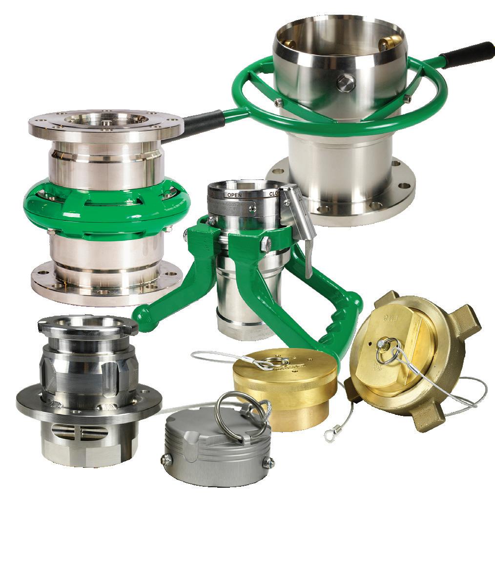
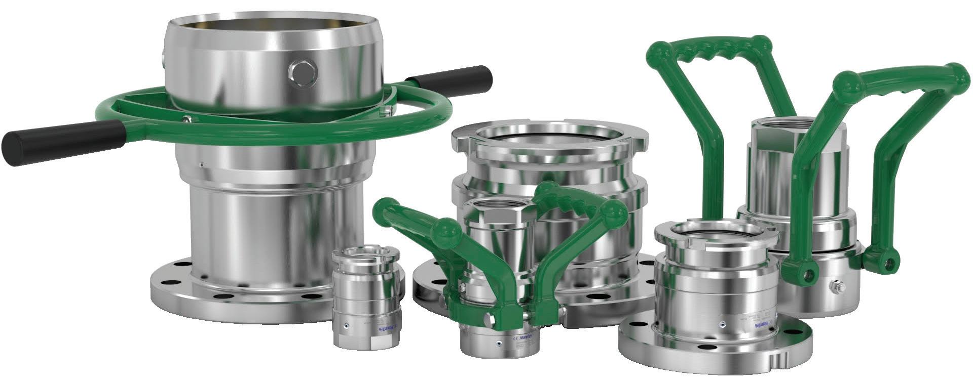
Cryogenic Dry Disconnect Couplings
Applications
• Container discharge
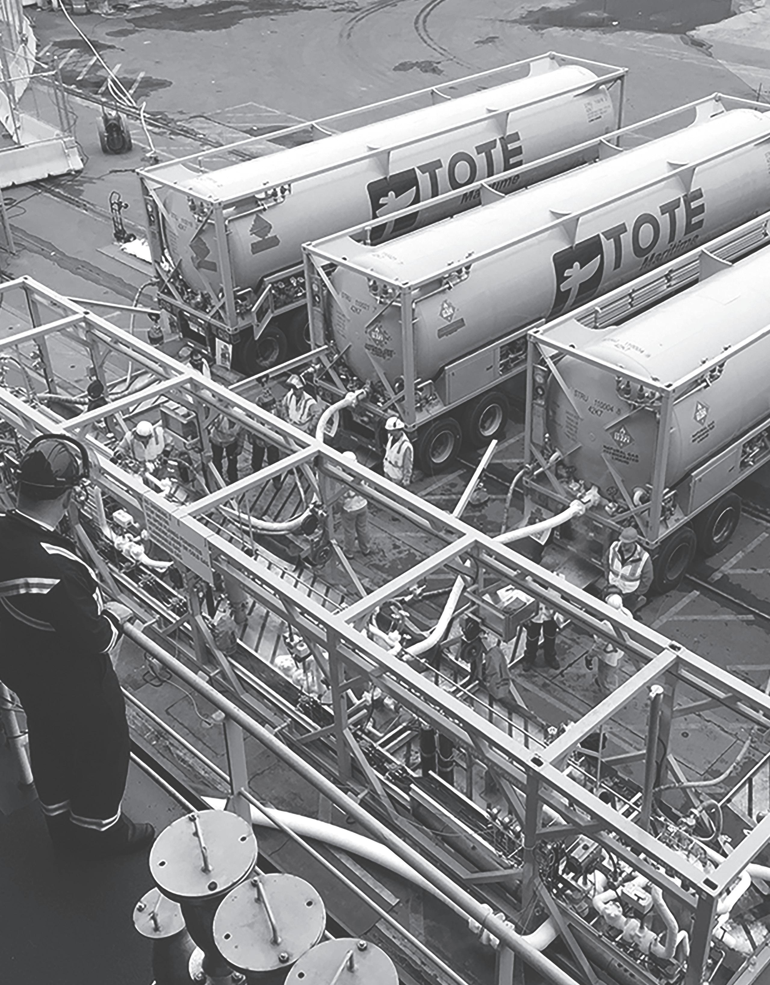
• Fuel bunkering
• Loading / unloading of tank trucks, rail cars, and ship tankers
• Vapor recovery lines
Sizes
• 1" - 8"
Features
• Single-action operation uses a straight-forward turning motion to connect the couplings and open the flow path
• Safe and reliable: valve cannot be opened until the unit is coupled and it closes automatically when disconnecting, eliminating spills
• Used with a wide range of cryogenic liquefied gases without the risk of cross connection due to human error
• Over 6,000 LNG fuel bunkering operations since 2013
• Used for receiving and storing liquid oxygen, liquid hydrogen, and LNG for rocket and engine testing
Material
• Stainless steel
Specifications
• Connections: female NPT, flanged EN and ANSI, others available on request
• Working pressure: 1" to 4" at 360 PSI, 6" at 230 PSI
• Minimum working temperature: -328°F (-200°C)
Approvals
• Meets requirements for USCG 16715 CG-OES Policy Letter No. 02-15 use of dry disconnects and breakaway coupling/self sealing quick release
• Conforms to ISO/DTS 18683 dimensions for dry disconnects used for bunkering
• Couplings meeting ISO 21593 are available
• Meets MSC 95/3/4 (IGF code) Section 8.5 Requirements for bunkering system
• Meets The Society for Gas as a Marine Fuel (SGMF) Safety Guidelines for Bunkering
• Meets ASTM F3312/F3312M 18Standard Practice for Liquefied Natural Gas (LNG) Bunkering Hose Transfer Assembly
• DNV, NKK, and BV type approved
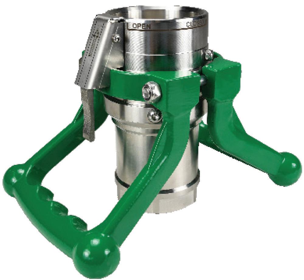
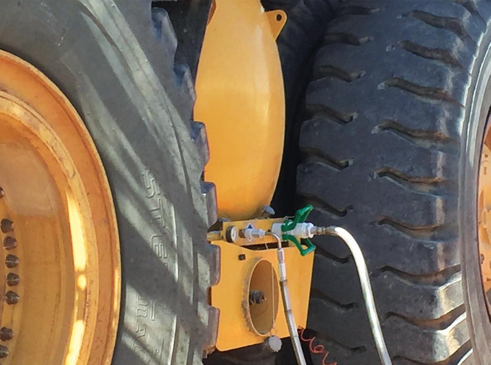
Dry Disconnect Couplings for Fueling Mobile Equipment
Applications
• Fueling on-highway trucks
• Fueling off-highway mobile equipment Size
• 2", contact Dixon® for other sizes
Features
• Single-action operation uses a straight-forward turning motion to connect the couplings and open the flow path
• Safe and reliable system:
- valve cannot be opened until the unit is coupled
- valve closes automatically when disconnecting coupler
- a safety detent applies when disconnecting coupler
• Used with a wide range of cryogenic liquefied gases without the risk of cross connection due to human error
Material
• Stainless steel
• PTFE seals
Specifications
• Coupler connection is female NPT
• Receptacle is flanged for easy install, or female NPT connection
• 360 PSI working pressure
• -328°F (-200°C) minimum working temperature
Approvals
• Conforms to ISO/DTS 18683
• DNV, NKK, and BV type approved
Cryogenic Dry Disconnect Couplings
How It Works
To connect:
Push and turn - it's coupled at full flow
To disconnect:
Turn and pull - it's released, no spillage
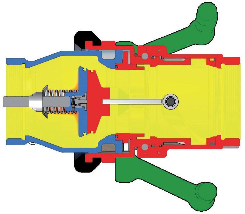
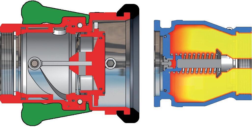
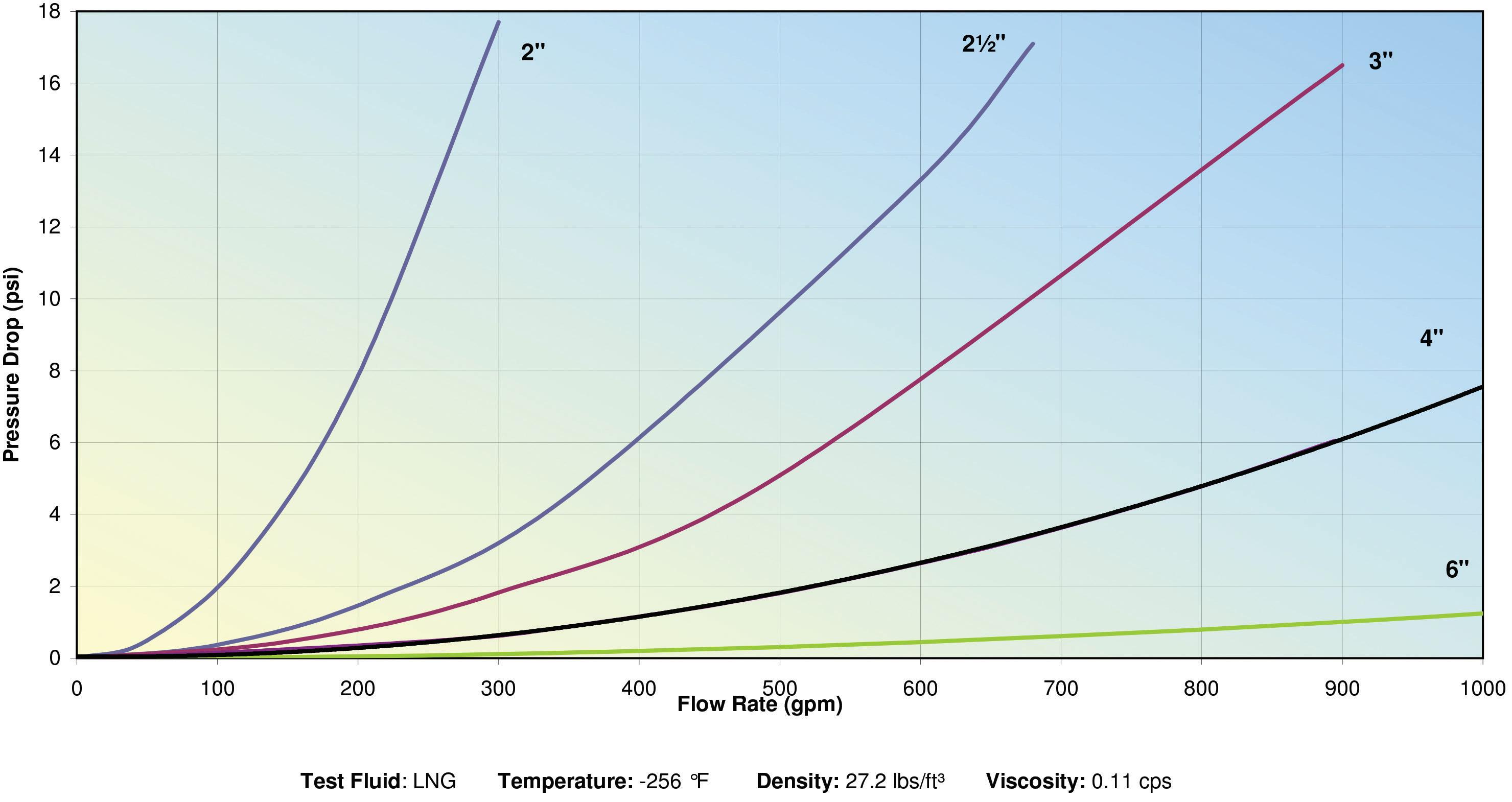
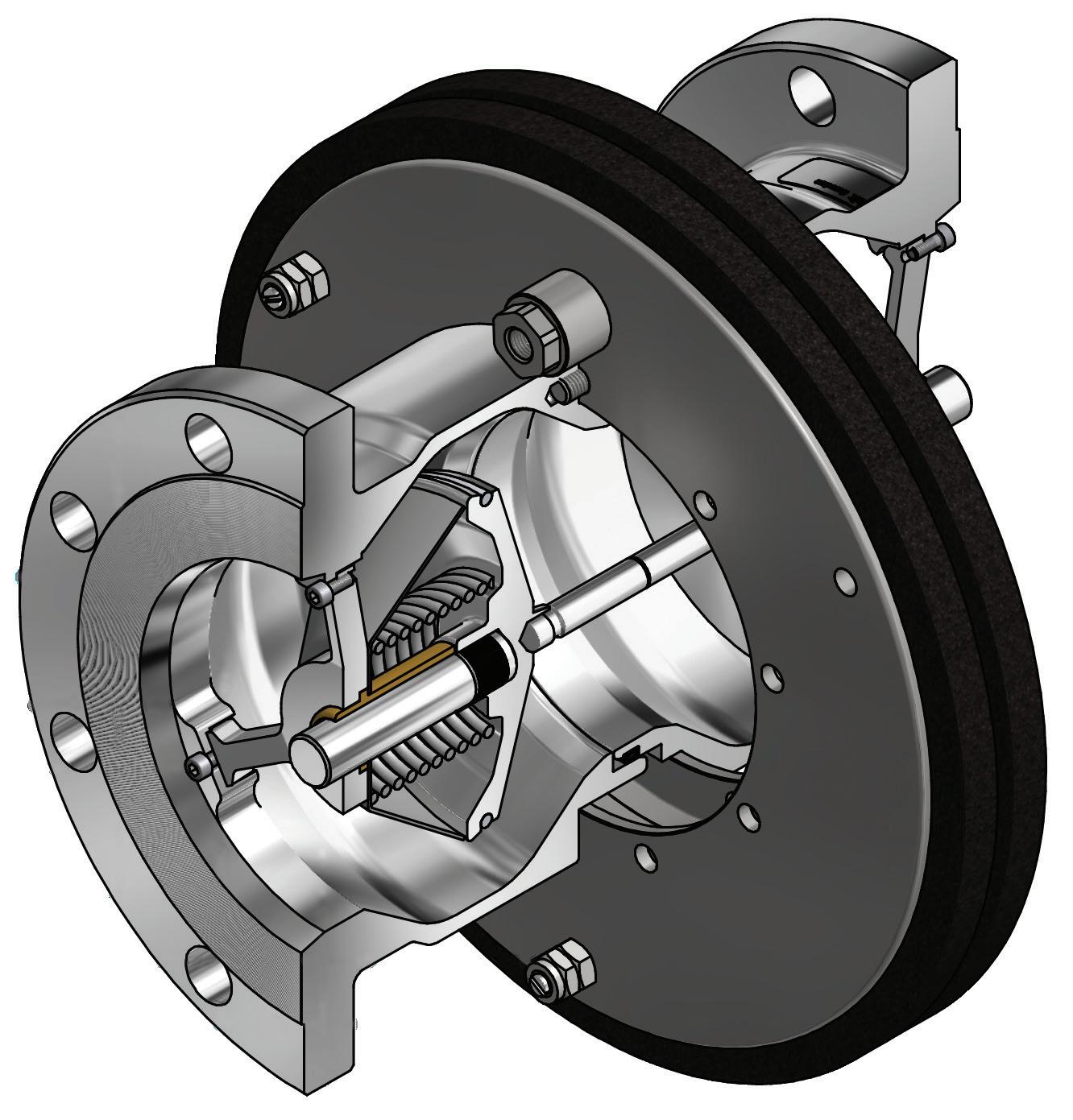
Dry cryogenic couplings consist of a tank unit or adapter with a spring loaded poppet and a hose unit or coupler with a valve driven by an internal cam. To couple, simply align the rollers on the coupler with the notches on the adapter, push the coupler onto the adapter and rotate past 100 degrees. This simple process locks the coupling together, creates a self-seal and opens the internal valves for full flow with low pressure drop. The duel poppet design shut-off mechanism safely seals liquids and gases behind the valve, eliminating fugitive emissions and the danger of a spill of cryogenic fluids.
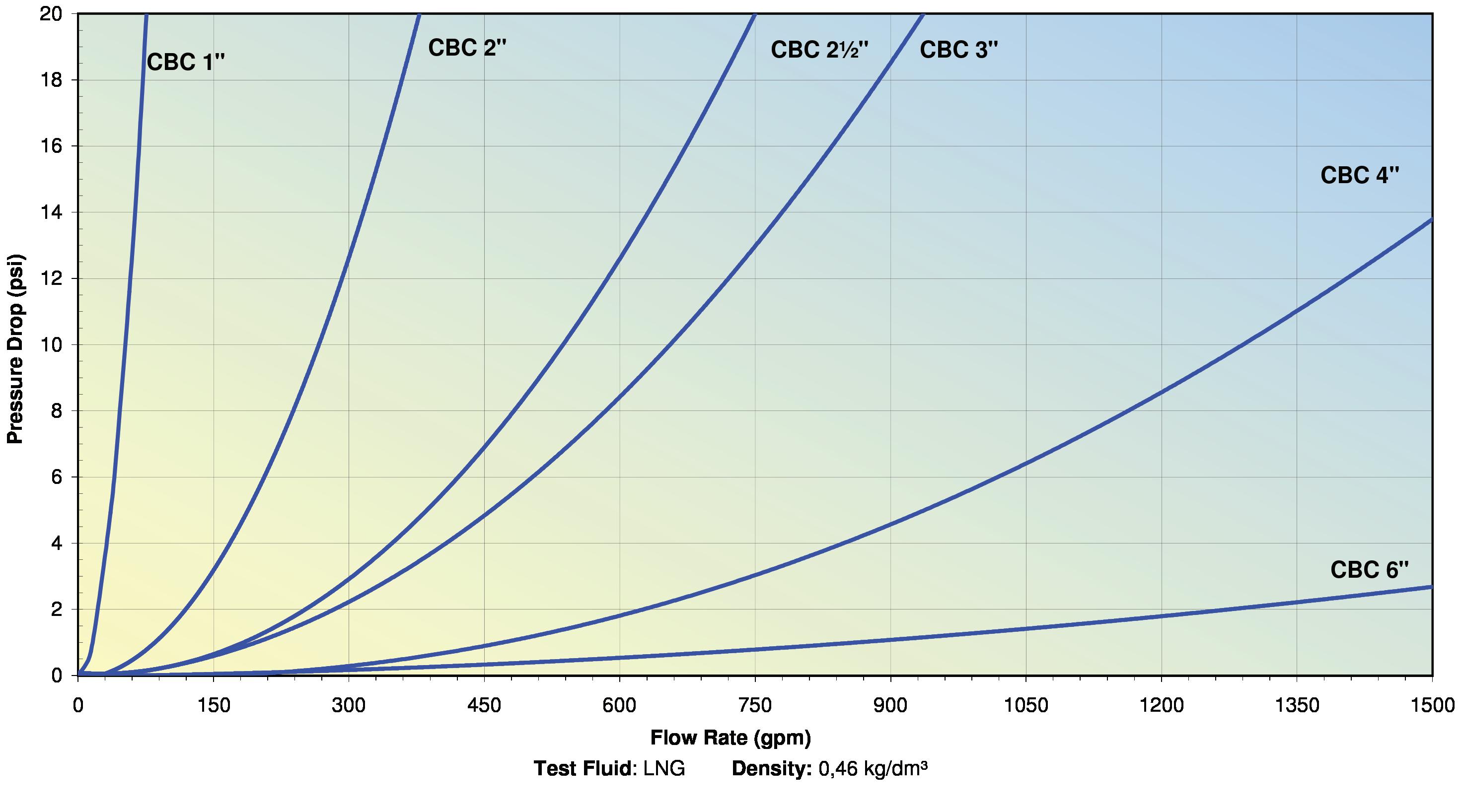
Flow Diagram
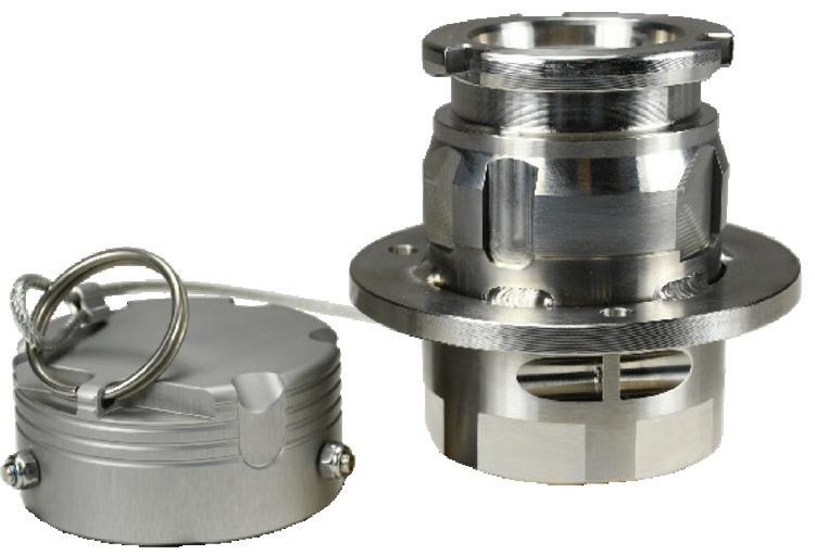
LNG30BRFE fixed end with cap
LNG30BRHE hose end with plug
Liquified Natural Gas (LNG) Couplings
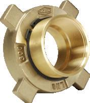
LNG30BRFE-NC fixed end
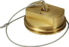
LNGBRFECAP fixed end cap
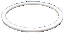
LNG30FESEAL seal
LNG30BRHE-NC hose end
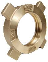
LNG30BRHENUT hose end
LNGBRHEPLUG hose end plug
Application
• Safe and reliable transfer of cryogenic LNG products to transport equipment such as cargo tanks, portable tanks, and liquified natural gas liquid production facilities
Sizes
• 2" and 3"
Features
• Fixed end design threads on tank truck pipe connection line, manifold, pipe outlet, or pipe connection
• PTFE gasket reduces force needed to make a tight connection
• Connect by hammering the acme threaded nut onto a fixed end
• Hose end designed female NPT thread attached to hose end
• Snap ring keeps connection nut in place for easier connecting
• Hose end lugs intended to be struck with a non-sparking hammer or similar non-sparking device
Materials
• Body: brass
• Seal: PTFE
Specifications
• Compatible with LNG couplings made to CGA guidelines
• Temperature as low as -320°F (-196°C) at standard LNG transfer pressures
• 450 PSI working pressure with 4-to-1 safety factor
Approvals
• Meets CGA V-6 LNG-30 guidelines
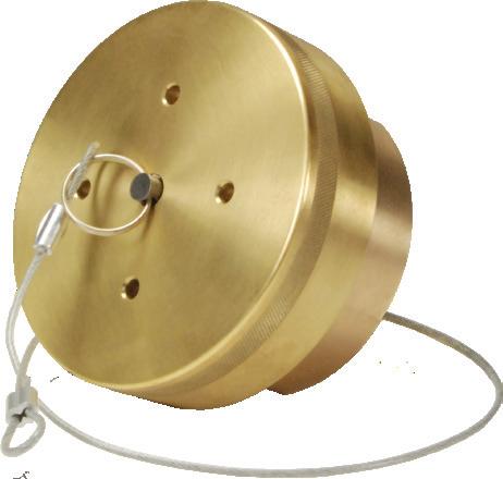
2" LNG30 fixed end with 2" female NPT thread / cap and retaining cable
LNG20BRFE
3" LNG30 fixed end with 3" female NPT thread / cap and retaining cable LNG30BRFE
3" LNG30 fixed end with 3" female NPT thread
3" LNG30 PTFE seal
LNG30BRFE-NC
LNG30FESEAL Cap for LNG30BRFE and LNG20BRFE
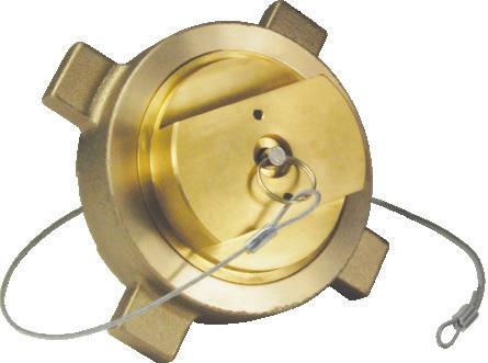
2" LNG30 hose end with 2" female NPT thread / with plug and retaining cable
3" LNG30 hose end with 3" female NPT thread / with plug and retaining cable
3" LNG30 hose end with 3" female NPT thread
3" LNG30 swivel nut
LNGBRFECAP
LNG20BRHE
LNG30BRHE
LNG30BRHE-NC
LNG30BRHENUT Plug for LNG30BRHE and LNG20BRHE
LNGBRHEPLUG
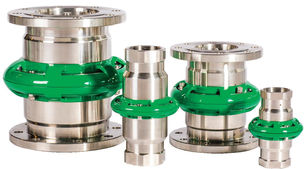
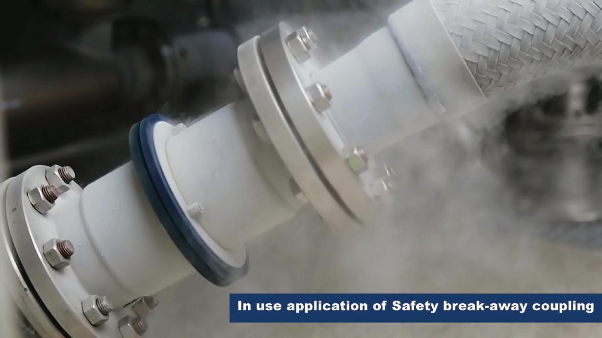
Cryogenic Breakaway Couplings
Applications
• Container discharge
• Fuel bunkering
• Loading / unloading of tank trucks, rail cars, and ship tankers
• Vapor recovery lines
Sizes
• 1" - 8"
Features
• Operates independently of shut-off safety system and does not require an external power source
• Lightweight, easy to reset and repair on site with one person
• High flow rate / low pressure drop
• Positive shut-off of both coupling halves results in minimum product loss
• Passive security where a hose or loading arm could be subjected to inadvertent excessive loads
• Can be installed at fixed points or in the middle of hose strings
• Available as industrial or marine types
• No loose components that could be lost after release
Material
• Stainless steel
Specifications
• Connections: female NPT, flanged EN and ANSI, others available on request
• Working pressure: 1" to 4" = 360 PSI, 6" = 230 PSI
• Minimum working temperature: -328°F (-200°C)
Cryogenic Breakaway Couplings
How It Works
The cryogenic breakaway couplings have three external break bolts. In the case of axial tension all the bolts take up the force corresponding to the break force on the hose with a safety margin.
Non-axial forces concentrate the tension forces more strongly on one bolt, so that the safety breakaway coupling reacts in a natural way to the reduction of the hose break forces.
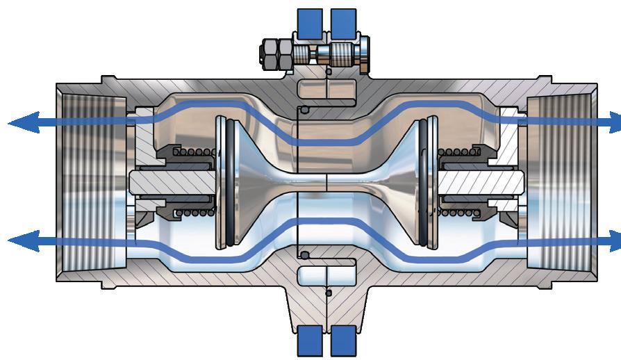
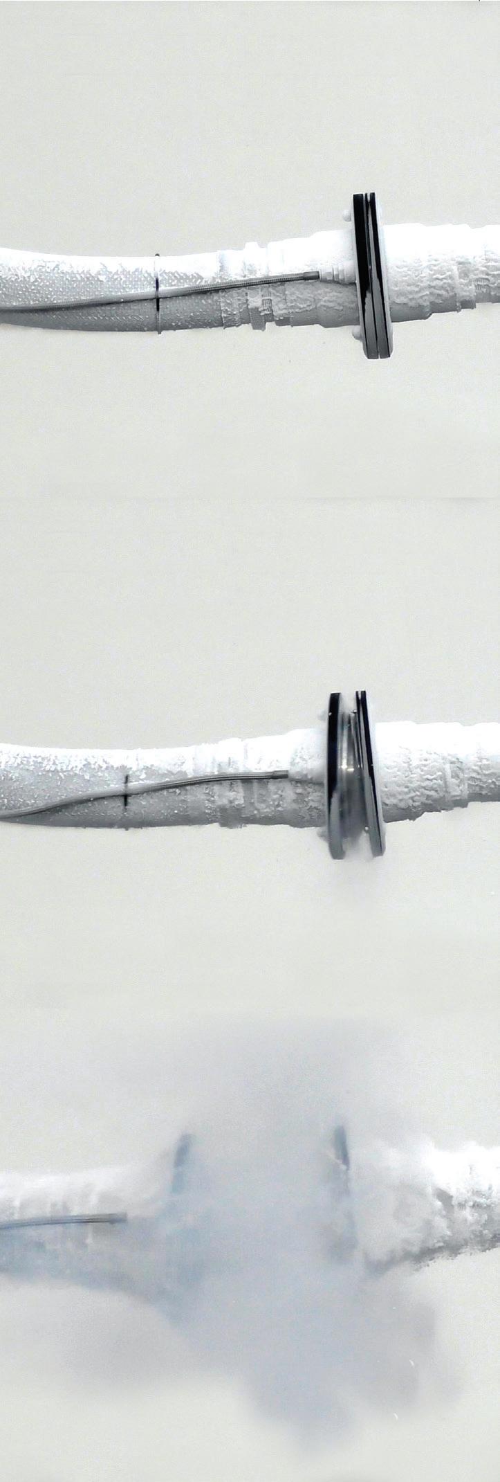
BEFORE emergency disconnect
The safety breakaway valve consists of two halves, each with a valve that has an O-ring seal.
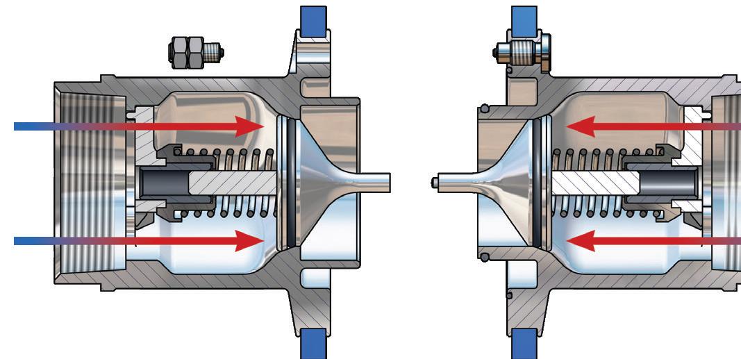
AFTER emergency disconnect
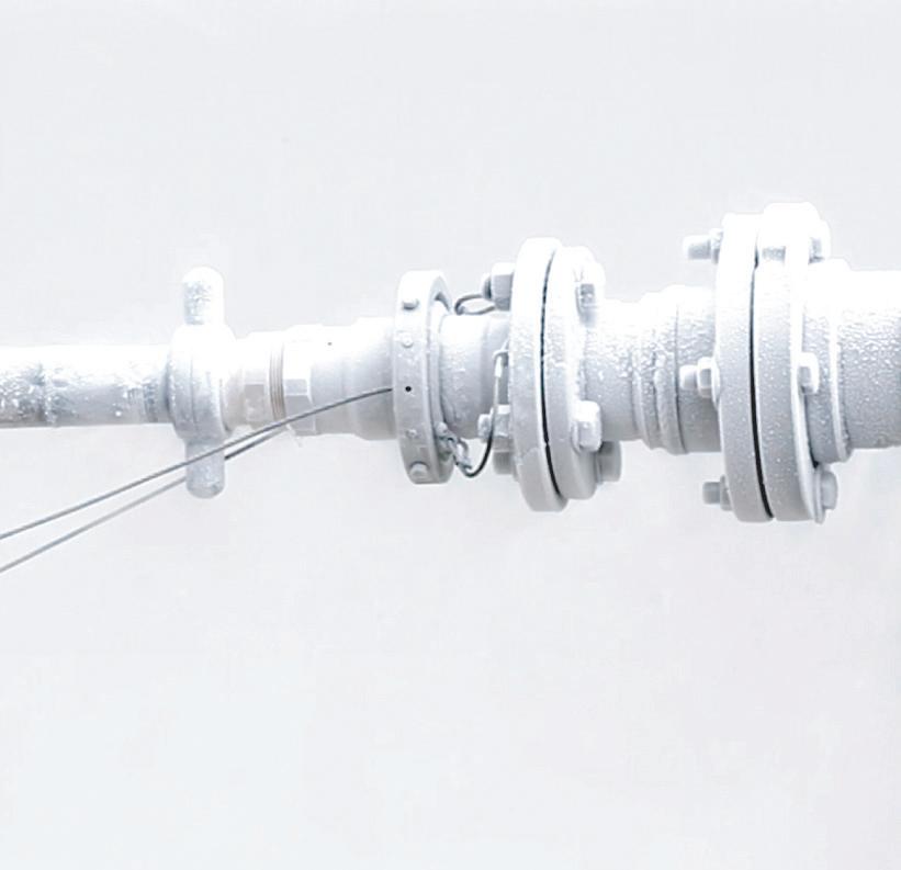
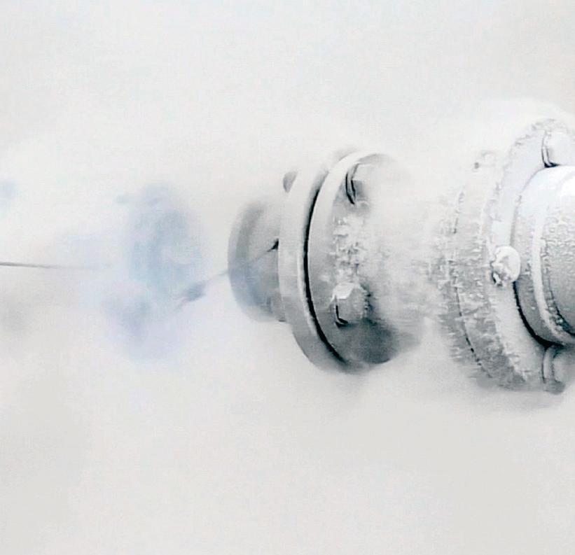
When the cryogenic breakaway couplings separate, the valves are able to close. The two valves close rapidly, minimizing exposure to personnel and the environment.
Flow Diagram
Power Emergency Release Coupling (PERC)
Applications
• Fuel bunkering
• Loading / unloading of tank trucks, rail cars, and ship tankers
• Vapor recovery lines
Sizes
• 4" (DN100) to 8" (DN200), others on request
Features
• Two halves close when there is excessive force or when pressurized nitrogen is introduced to the coupling halves from a control unit to break the bolts and separate the couplings
Materials
• Stainless steel
• Seal: PTFE
Specifications
• Calculation of the required wall thickness is made according to EN 12516-2
• Material is suitable for use with LNG and nitrogen to -328°F (-200°C) according to the recommendations in EN1160
• Conforms to specification EN10272 1.4404
• 316L conforms to specification ANSI A479
• Connections: NPT thread, EN1092 (DIN) or ANSI B16.5 flanges, others on request
• Temperature range: -328°F (-200°C) to 150°F (65°C)
• Recommended nitrogen supply pressure: 200 Bar (min 150 Bar)
• Recommended nitrogen latent seal pressure: 2 Bar
• Recommended tube / hose internal dimension: max 6.35 mm (1/4")
• Recommended tube / hose length: max 100m (smooth surface hose)
• Time to release: < 2 sec
• Gas consumption: max ~ 0.6 m3
Example of power emergency release coupling
N2 Port
Poppet
Breaking Bolt
Power Emergency Release Coupling (PERC)
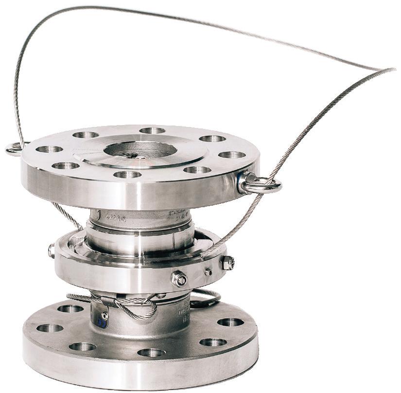
Breaking Pin Type Breakaways •SAFE!
•SEPARATE ON COMMAND!
The Mann Tek Cryogenic PERC design combines the passive safety feature known from our breaking pin type breakaways with the ability to separate on command without any force on the hose. When actuated by a remote control, a pressurized gas cylinder will open and gas pressure will overcome the breaking bolts. The PERC system corresponds to standard EN1474-1:2008.
TRUCK to SHIP Bunkering
Cryogenic Breakaway Couplings – Cable Release
Applications
• Plant engineering, power plant construction, chemical industry, food processing, process technology, and tank cleaning
• Filling systems: railroads, rail cars, tank trucks, ships, tank containers, and liquefied gas
Sizes
• 1" (DN25) to 8" (DN200), others on request
Features
• Sturdy design
• Safe operation
• Release angle up to 90° by cable activation
• Maintenance friendly
• Break force does not change with system pressure or angle of pull
• Protects system components by minimizing the amount of stress placed on system
Materials
• Stainless steel
• Seals: PTFE
Specifications
• Calculation of wall thickness is made according to SS-EN 12516-2
• Material is suitable for use with LNG and Nitrogen to -328°F (-200°C) according to the recommendations in EN1160
• Connections: NPT thread, EN1092 (DIN) or ANSI B16.5 flanges, others on request
• Temperature range: -328°F (-200°C) to 150°F (65°C)
• Pressure: PS25 Bar
• Conforms to specification EN10272 1.4404
• 316L conforms to specification ANSI A479
Example of cable release coupling
Cryogenic Products
Applications
• Cryogenic piping systems
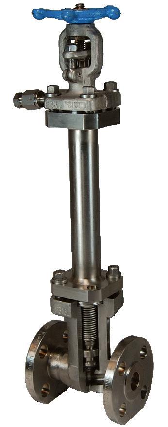
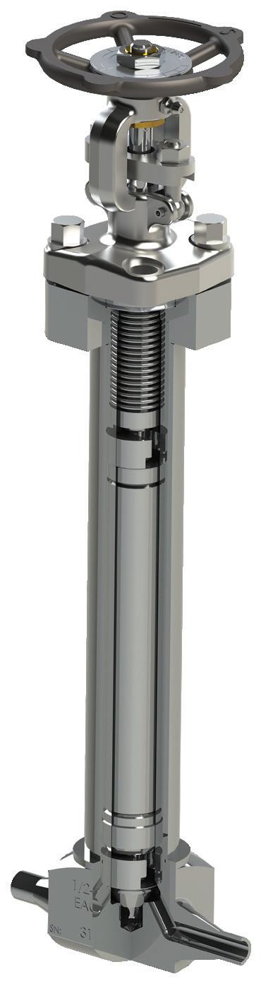
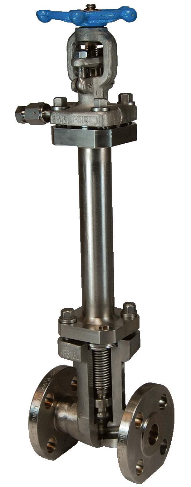
Cryogenic Globe Valves
1/2” - 2” BOLTED BONNET WITH CRYOGENIC EXTENSION
• High purity industrial gas tanks
• ISO containers
• Transportation trailers
• Typical fluids:
- LNG - Hydrogen
- Argon - Oxygen
- Nitrogen
Sizes
• 1/2” to 2”
Features
• Field repairable / repair kits available
• Butt weld pipe or tube ends
• Options:
- Soft seat: PCTFE or PTFE
- Purge ports
- Graphite packing / gaskets
- Electropolished interior
- Air actuation
Materials
• Body: 316L stainless steel from bar stock
• Bonnet: F316L stainless steel
• Body seat: 316L stainless steel
• Bellows: Inconel® rated for 10,000 cycles
• Packing: PTFE
• Bonnet Gasket: PTFE/316 stainless steel
Specifications
• Operating temperature: -452°F to 300°F (-269°C to 149°C)
• Operating pressure: Per ASME B16.34 CL800
• Testing:
- External leakage / structural integrity
Hydro to API 598 CL800
Helium mass spectrometer to 1x10⁻⁷scc He/sec
- Seat Leakage
Hydro to API 598 CL800
Bubble tight to 600 PSIG nitrogen
Dixon Eagle valves are designed to work safely for their intended use. Failure to know and understand the intended use or to consider the size, temperature, application, media, pressure, and manufacturers recommendations when selecting the proper valve assembly components can result in accidents and injuries, including death and serious and permanent injuries. Dixon® recommends that all valve assemblies be tested in accordance with ASME and API recommendations and be inspected regularly to ensure that their use remains appropriate and that they are not damaged.
At no charge, Dixon is available to consult, train, and recommend the proper selection and application of all valves we sell. We strongly recommend that distributors and end users make use of Dixon’s Testing and Recommendation Services. Contact Dixon® to learn more.
Bill of Materials
Tube Ends/ Buttweld Globe Valves Dimensions
Notes
DIXON VALVE AND COUPLING COMPANY, LLC (herein called "Dixon") warrants the products described herein and manufactured by Dixon to be free from defects in material and workmanship for a period of one (1) year from date of shipment by Dixon under normal use and service. Its sole obligation under this warranty being limited to repairing or replacing, as hereinafter provided, at its option any product found to Dixon's satisfaction to be defective upon examination by it, provided that such product shall be returned for inspection to Dixon's factory within three (3) months after discovery of the defect. The repair or replacement of defective products will be made without charge for parts or labor. This warranty shall not apply to: (a) parts or products not manufactured by Dixon, the warranty of such items being limited to the actual warranty extended to Dixon by its supplier; (b) any product that has been subject to abuse, negligence, accident, or misapplication; (c) any product altered or repaired by others than Dixon; and (d) to normal maintenance services and the replacement of service items (such as washers, gaskets, and lubricants) made in connection with such services. To the extent permitted by law, this limited warranty shall extend only to the buyer and any other person reasonably expected to use or consume the goods who is injured in person by any breach of the warranty. No action may be brought against Dixon for an alleged breach of warranty unless such action is instituted within one (1) year from the date the cause of action accrues. This limited warranty shall be construed and enforced to the fullest extent allowable by applicable law.
Other than the obligation of Dixon set forth herein, Dixon disclaims all warranties, express or implied, including but not limited to any implied warranties of merchantability or fitness for a particular purpose, and any other obligation or liability. The foregoing constitutes Dixon's sole obligation with respect to damages, whether direct, incidental, or consequential, resulting from the use or performance of the product.
Some products and sizes may be discontinued when stock is depleted or may require a minimum quantity for ordering.
About This Catalog and Our Products
This catalog is intended as a product offering. It is not a user or technical manual. Information in this catalog is subject to change without notice. We may modify product design and specification without notice and without any obligation to modify or substitute products previously purchased. All users and distributors of products sold through this catalog are strongly encouraged to contact Dixon with questions on use, compatibilities, coupling procedures, and life of product. Our full-time engineering and test staff are always available to recommend uses and to assist distributors and users with questions.
Limited Warranty Safety
Safety logos, which appear throughout our catalog, are used as a reminder that the user should carefully review for the appropriateness of the product for the media, application, and environment in which it will be used.
NOTE: Because of the health hazards associated with contamination and lead content in drinking water systems, Dixon couplings, unless otherwise specifically approved, are not recommended for potable water service and should not be used in applications where drinking water will contact the wetted surfaces of the coupling.
All Dixon products are shipped in cartons with the following warning: "WARNING: This product contains lead, a chemical known to the State of California to cause cancer and birth defects or other reproductive harm."
Trademarks
Delrin® and Zytel® are registered trademarks of E.I. duPont Nemours and Company.
Kalrez® is a registered trademark of DuPont Dow Elastomers.
All other trademarks appearing in the Dixon illustrated price list are the property of their respective owners.
All rights reserved. This book is copyrighted material. Use, reproduction or copying of it by anyone other than Dixon® is strictly forbidden without its express written consent.
NOTE: Reasonable care has been taken in preparing this catalog. Dixon Valve & Coupling Company, LLC reserves the right to make corrections.