

Quick Coupling Selection Guide
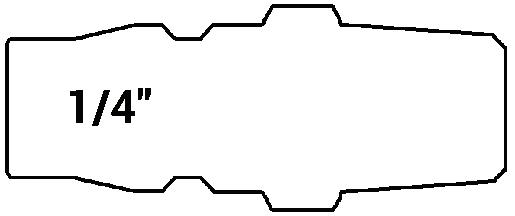
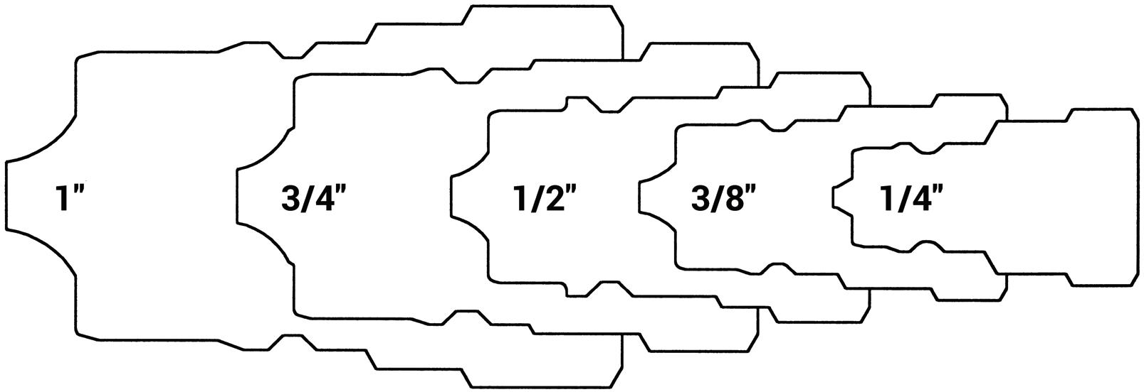
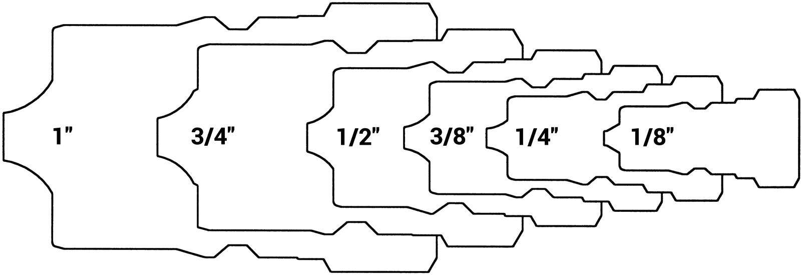
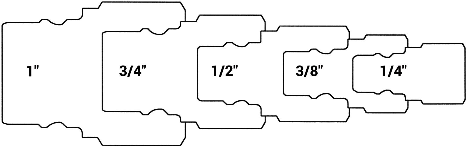
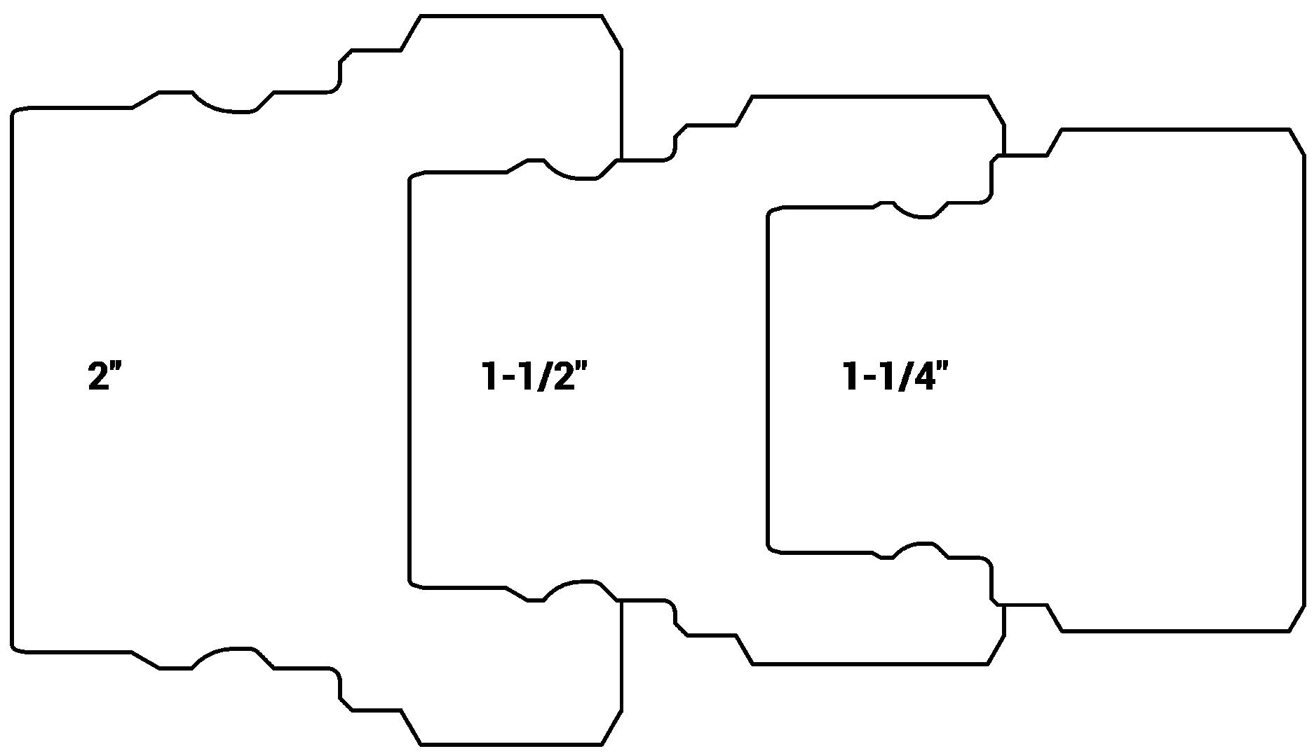
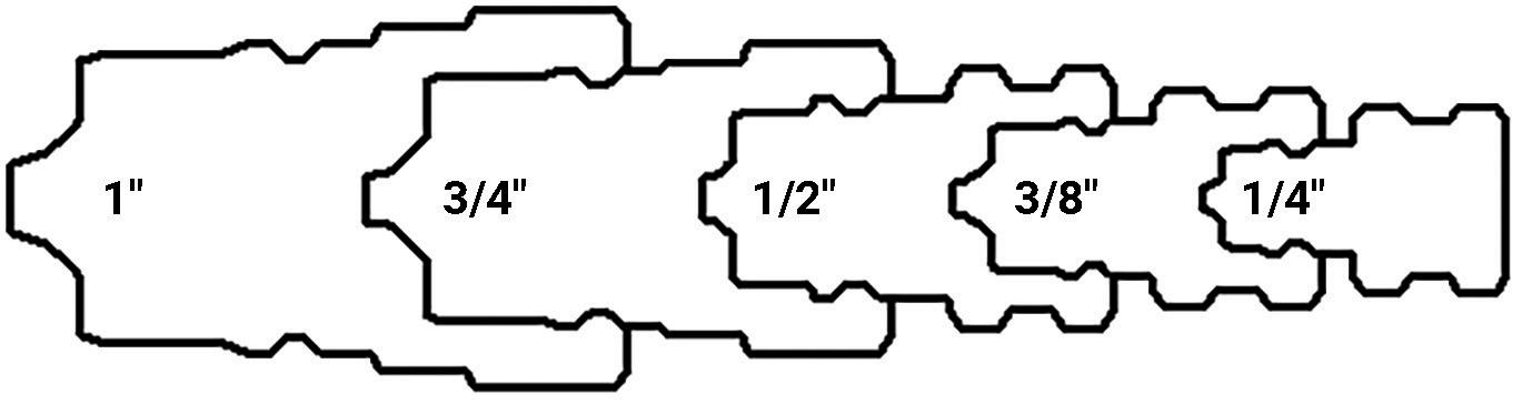
1. Determine the profile (shape) of the plug. Compare your plug shape with the profile chart below to identify the Dixon Quick Coupling pneumatic or hydraulic series.
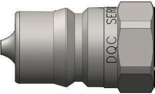
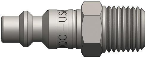
2. Body size dimension charts can be found within each series section. Measure the A (diameter) and B (tip length) dimensions to determine the plug body size (figure 1).
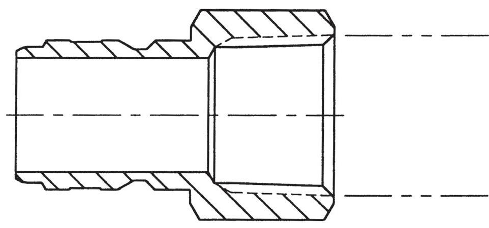
3. Use the industry standard thread chart below (or diagram on page 6) to determine the end connection thread size. If you have a hose barb, the ID measurement of your hose will determine the barb size (figure 2).
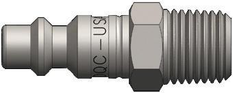
Pneumatic Profile Shape
Interchange page 20
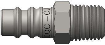
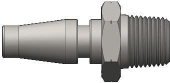
page 39
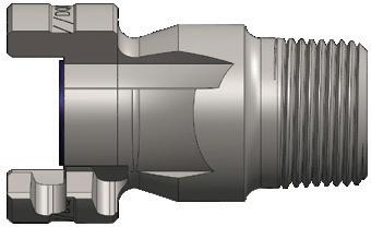
page 57
page 42
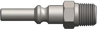
page 45
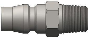
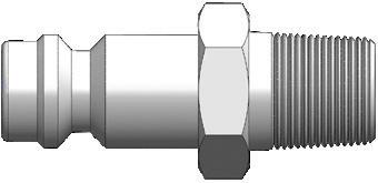
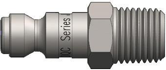
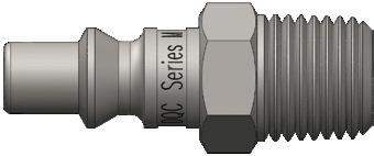
page 30
page 35
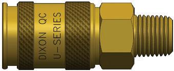
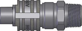
page 47
page 49
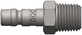
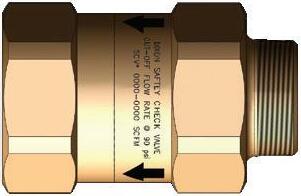
fig. 2
fig. 1
Hydraulic Quick Coupling Selection Guide
Hydraulic Profile Shape
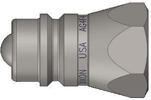
page 91
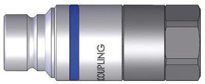
ISO16028 Connect Under Pressure Plug pages 125
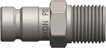
ISO7241-B page 70
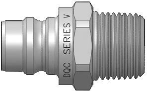
page 96
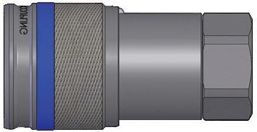
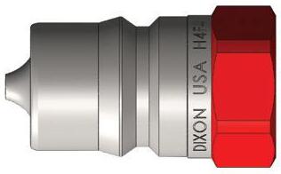
ISO7241-B BOP page 80
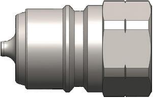
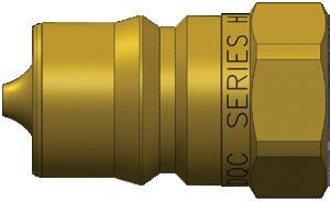
ISO7241-B Steam page 82
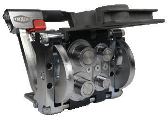
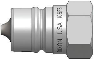
ISO7241-A page 85
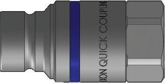
page 113 Modular Connection System page 115 Correct Connect® ISO16028 page 117
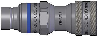
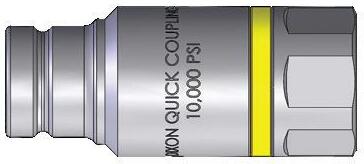
ISO16028 Connect Under Pressure Coupler page 128 ISO16028 - AG ISO7241-A page 129 10K Flush Face page 130
steel • 316 ss
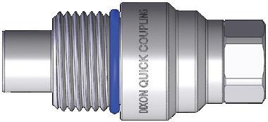
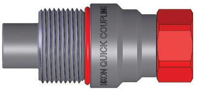
ISO15171-1 Test page 138 Threaded Flush Face page 140 Wingstyle page 147
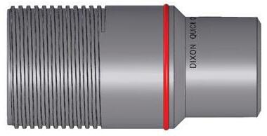
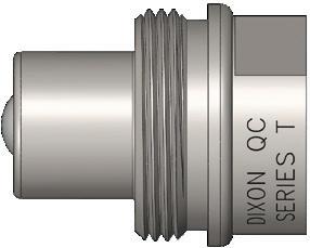
Wingstyle BOP page 158 10K Threaded page 160
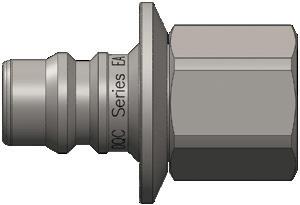
Blast page 175
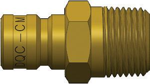
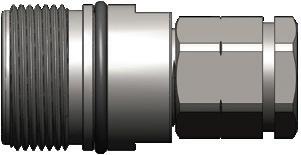
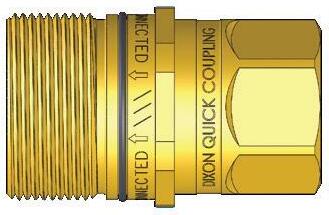
page 149
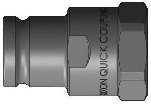
Flush Face page 132
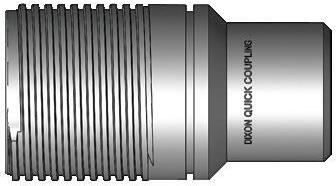
Wingstyle page 152
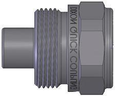
ISO14541 page 163 15K and 20K Threaded page 167
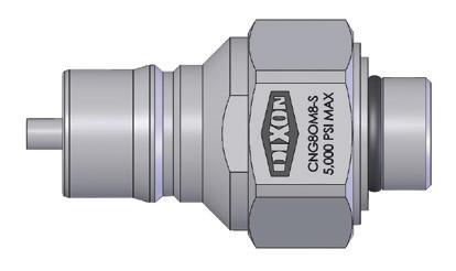
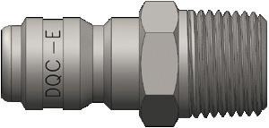
page 169
Competitor Series or Standard Manufacturer Dixon Series Page(s)
10000-Series TEMA TR-Series 115
1000-Series Hansen F-Series 20
10-Series Parker J-Series 30
1110-Series Tomco L-Series 45
13-Series Rectus NK-Series 61
20-Series Parker F-Series 20
210/310 Foster M-Series 35
210/310 Hansen M-Series 35
210/310 Milton M-Series 35
21KA Rectus BR-Series 63
223-Series CEJN BR-Series 63
25KA Rectus CJ-Series 39
26KA Rectus CJ-Series 39
27KA Rectus CJ-Series 39
3000-Series Hansen D-Series 20
3000-Series Parker/Pioneer T-Series 160
30-Series Parker D-Series 20
300-Series Oasis CNG-Series 85
315-Series CEJN NK-Series 61
320-Series CEJN CJ-Series 39
3800-Series TEMA TR-Series 115
3FFH-Series Faster HTE-Series 125
3-Series Foster DF-Series 20
4000 Series Parker/Pioneer AG-Series 93
4000-Series Hansen D-Series 20
400-Series Hansen F-Series 20
410-Series CEJN CJ-Series 39
4-Series Foster DF-Series 20
5000-Series Hansen D-Series 20
5000-Series TEMA TR-Series 115
500-Series Hansen F-Series 20
50-Series Parker M-Series 35
51000-Series Bowes N-Series 49
5100-Series Eaton/Aeroquip W-Series 147
525-Series CEJN TR-Series 115
55KM Rectus J-Series 30
56-Series Snap-Tite EA-Series 175
5-Series Foster DF-Series 20
5TV/6TV-Series Hydraulics Inc WS-Series 152
6000-Series Hansen D-Series 20
Competitor Series or Standard Manufacturer Dixon Series Page(s)
60-Series Parker H-Series 70
60-Series Snap-Tite AG-Series 93
60-Series Steam Parker HS-Series 82
6100-Series Foster W-Series 147
6100-Series Parker W-Series 147
61-Series Snap-Tite K-Series 87
6600-Series Parker K-Series 87
6-Series Foster DF-Series 20
70-Series Parker L-Series 45
71-Series DNP ST-Series 132
71-Series Snap-Tite ST-Series 132
72-Series Snap-Tite H-Series 70
74-Series Snap-Tite HT-Series 117
7500-Series TEMA TR-Series 115
75-Series Snap-Tite WS-Series/ WS-BOPSeries 152 and 158
76-Series Snap-Tite T-Series 160
78-Series Snap-Tite W-Series 147
A2100/PT400 Tomco J-Series 30
A-A-50431A U.S. Government N-Series 49
A-A-59439 U.S. Government DF-Series 20
ANV-Series DNP K-Series 87
ANV-Series Faster K-Series 87
APM-Series Stucchi HTE-Series 125
ARO Interchange M-Series 35
A-Series National P-Series 57
A-Series Stucchi HT-Series 117
Auto-Flo 23 Hansen U-Series 47
Automotive Interchange J-Series 30
BIR-Series Stucchi K-Series 87
Bowes Interchange N-Series 49
B-Series National N-Series 49
C604 Enerpac T-Series 160
Correct Connect® Trademark HT-Series 117
CQD-Series Spir Star TD-Series 167
CRS-Series DNP TD-Series 167
CS-Series Nycoil SHD-Series 42
CVV-Series Faster CVV-Series 163
Dixlock Trademark N-Series 49
Cross Reference Tool
Competitor Series or Standard Manufacturer Dixon Series Page(s)
Double Lock Campbell P-Series 57
D-Series DNP PD-Series 138
Dual-Lock Trademark P-Series 57
European ScrewTogether Interchange CVV-Series 163
European Nycoil CJ-Series 39
European High-Flow Interchange CJ-Series 39
FB-Series Faster W-Series 147
FD45 Eaton/Aeroquip H-Series 70
FD56 (5600) Series Eaton/Aeroquip K-Series 87
FD69-Series Eaton/Aeroquip EA-Series 175
FD85-Series Eaton/Aeroquip WS-Series 152
FD89-Series Eaton/Aeroquip HT-Series 117
FD90-Series Eaton/Aeroquip PD-Series 138
FD96-Series Eaton/Aeroquip VEP-Series 140
FEC-Series Parker HTE-Series 125
FEM-Series Parker HT-Series 117
FET-Series Parker VEP-Series 140
FF49-Series Safeway HT-Series 117
FFEC49-Series Safeway HTE-Series 125
FF-GP Series DNP HT-Series 117
FFK-Series DNP HTE-Series 125
FFN/FFI/2FFN/2FFI Faster HT-Series 117
FF-Series Hansen HT-Series 117
FF-Series Parker HT-Series 3/8" only 117
FHK-Series Foster H-Series 70
FH-Series Voswinkel HTE-Series 125
FIH/FH Foster V-Series 98
FIRG Stucchi HT-Series 117
FJT-Series Foster CM-Series 177
Flo-Temp Hansen CM-Series 177
FSI-BOP-Series DNP VEP-BOPSeries 145
FS-Series Hansen SCV-Series 68
FST-Series Foster E-Series 169
FT-Series Voswinkel VEP-Series 140
FVEP-Series Foster VEP-Series 140
H/IH-Series Snap-Tite V-Series 98
HA15000 Hansen K-Series 87
HCP-Series Holmbury HTE-Series 125
Competitor Series or Standard Manufacturer Dixon Series Page(s)
HFB-Series Holmbury E-Series 169
HFT-Series Holmbury VEP-Series 140 High Pressure Screw-Together Interchange T-Series 160
HKFR-Series Eaton/Hansen H-BOPSeries 80
HK-Series Hansen H-Series 70
HNV-BOP-Series DNP H-BOPSeries 80
HNVFR-Series Faster H-BOPSeries 80
HNV-Series DNP H-Series 70
HNV-Series Faster H-Series 70
HQ-Series Holmbury HT-Series 117
HSS-Series Holmbury HT-Series 117
HTN-Series Holmbury V-Series 98
IA/IAZ-Series Holmbury K-Series 87
IA-Series Voswinkel K-Series 87
IB/IBZ-Series Holmbury H-Series 70
IB-Series Voswinkel H-Series 70 Industrial Interchange DF-Series 20
IRB/IRBO/IRBX Series Stucchi H-Series 70
IRC-Series Stucchi TR-Series 115
IR-Series Stucchi AG-Series 93
ISO14540 ISO Standard T-Series 160
ISO14541 ISO Standard CVV-Series 163
ISO15171-1 ISO Standard PD-Series 138
ISO16028 ISO Standard HT-Series 117
ISO5675 ISO Standard AG-Series 93
ISO6150B ISO Standard DF-Series 20
ISO7241-A ISO Standard K-Series 87
ISO7241-B ISO Standard H-Series 70
IVHP-Series Stucchi T-Series 160 Japanese Industrial Interchange NK-Series 61
JS-Series DME CM-Series 177
LC-Series Holmbury WS-Series 152
Lincoln Interchange L-Series 45
MC-Series Tomco CM-Series 177
Megaflow Coilhose CJ-Series 39
MIL-C-3486 Military Spec N-Series 49
MIL-C-4109F Military Spec DF-Series 20
Cross Reference Tool
Competitor Series or Standard Manufacturer Dixon Series Page(s)
Mil-C-51234 Military Spec V-Series 97
Mold Coolant Interchange CM-Series 177
Moldmate Parker CM-Series 177
MPX-Series Staubli HT-Series 117
MQS-A Series Manuli K-Series 87
MQS-B Series Manuli H-Series 70
MQS-D Series Manuli PD-Series 138
MQS-F Series Manuli HT-Series 117
MQS-FP Series Manuli HTE-Series 125
MQS-SC Series Manuli T-Series 160
Ni-Cupla Nitto Kohki NK-Series 61
NS-Series DNP AG-Series 93
NS-Series Faster AG-Series 93
NS-Series/Jiffy-Tite DME CM-Series 177
NV-Series Faster AG-Series 93
OGF-Series Faster ST-Series 132
OGVFR-Series Faster WS-BOPSeries 158
OGV-Series Faster WS-Series 152
PD-Series Parker PD-Series 138
PHC-Series Thor P-Series 57
Pioneer Agricultural Interchange AG-Series 93
PSB/PSP-Series Holmbury T-Series 160
PST4/FSI Series DNP VEP-Series 140
PVM-Series DNP T-Series 160
PVV3-Series DNP CVV-Series 163
PVV3-Series DNP CVV-Series 163
PVVM/PVSM-Series Faster T-Series 160
Quick-Action MacDonald N-Series 49
S10-Series Safeway H-Series 70
S20-Series Safeway AG-Series 93
S30-Series Safeway T-Series 160
S51-Series Safeway W-Series 147
S56-Series Safeway K-Series 87
Schrader Interchange SHD-Series 42
Screw Type Jet Stream TD-Series 167
SC-Series Tomco BR-Series 63
SHD-Series Foster SHD-Series 42
SH-Series Stucchi V-Series 98
Single Lock Campbell N-Series 49
Competitor Series or Standard Manufacturer Dixon Series Page(s)
STG-Series Inteva CVV-Series 163
Straight-Through Interchange E-Series 169
ST-Series DNP E-Series 169
ST-Series Hansen E-Series 169
ST-Series Parker E-Series 169
ST-Series Tomco E-Series 169
TEMA European Interchange TR-Series 115
TF-Series Foster J-Series 30 Thor Interchange P-Series 57
TL-Series Parker SHD-Series 42
TL-Series Tomco SHD-Series 42
TNL-Series Faster V-Series 98
TNV-Series DNP V-Series 98
TNV-Series Faster V-Series 98
Tru-Flate Eaton/Hansen J-Series 30
Tru-Flate Hoffmann J-Series 30
Twist-Lock Schrader SHD-Series 42
Type B Amflo M-Series 35
Type-17 Coilhose L-Series 45
Type-HS Voswinkel CVV-Series 163
UC-Series Coilhose U-Series 47
UC-Series Parker U-Series 47
VD-Series Stucchi CVV-Series 163
VEP-HD Series Stucchi
VEP-P Series Stucchi
VEP-Series/ VEP-BOPSeries 140 and 145
VEP-Series/ VEP-BOPSeries 140 and 145
VFF-HD BOP-Series DNP WS-BOPSeries 158
VFF-HD Series DNP WS-Series 152
VFF-Series DNP W-Series 147
VOF-Series Stucchi WS-Series 152
Water-Blast Interchange EA-Series 175
WB-Series DNP EA-Series 175
WB-Series Parker EA-Series 175
Wing Style Stucchi W-Series 147
WS56000 Hansen T-Series 160
WSC-Series Holmbury W-Series 147
X64-Series CEJN HTE-Series 125
X65/X66-Series CEJN HT-Series 117
General Product Information
Male / Female Pipe (NPTF) Thread Identification
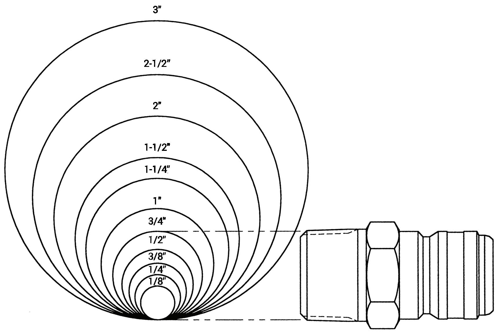
Female Pipe Thread Gauge
• Hold pipe thread against scale on edge of page
• Align one side of pipe thread with illustration base line
• Read nominal pipe size directly from scale
Male Pipe Thread Gauge
• Stand pipe thread vertically on diagram
• Align outside diameter of pipe thread with matching circle
• Read nominal pipe size directly above circle
Example: 3/4" male pipe (Dixon end size = 6)
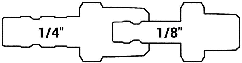
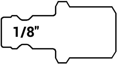
BR-Series
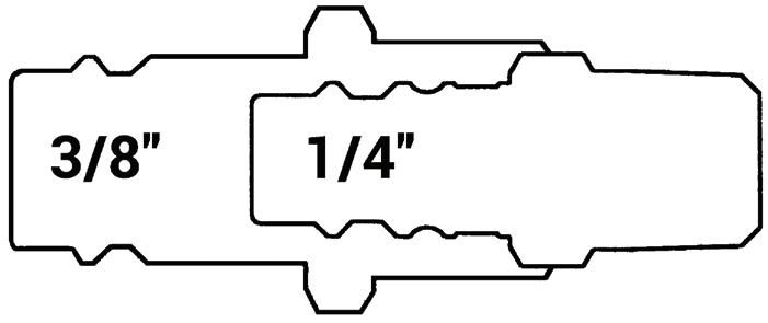
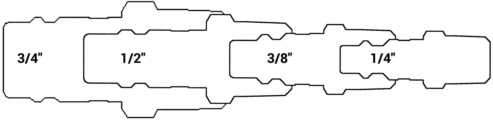
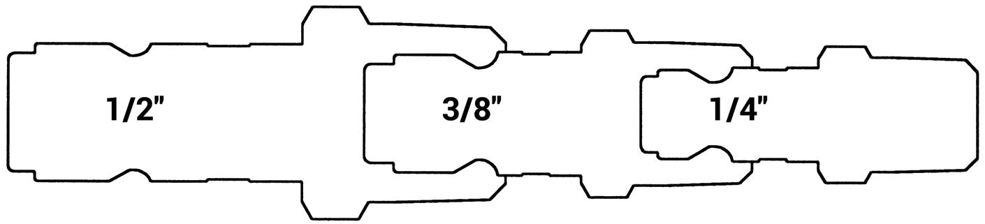
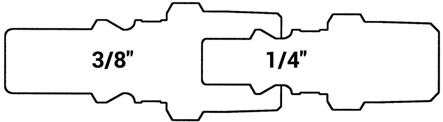
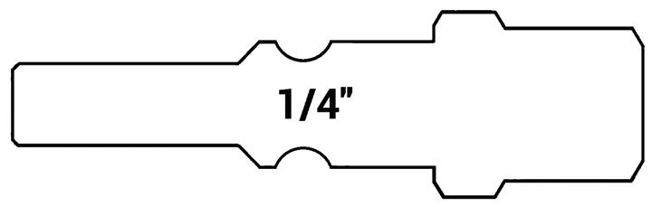
1/4" 1/2"
DF-Series
J-Series
M-Series
L-Series
NK-Series
A-Series
CJ-Series
SHD-Series
K-Series
K-Series 1" 3/4" 1/2" 3/8"
1" 3/4" 1/2" 3/8" 1/4"
AG-Series
Large
TR-Series
HT-Series
H-Series
Large H-Series
2-1/2"
V-Series
Large V-Series
W-Series 1-1/2" 1-1/4" 1" 3/4"
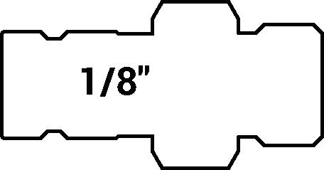
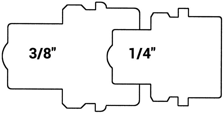
ST-Series
T-Series
Large ST-Series 2" 1"
PD-Series
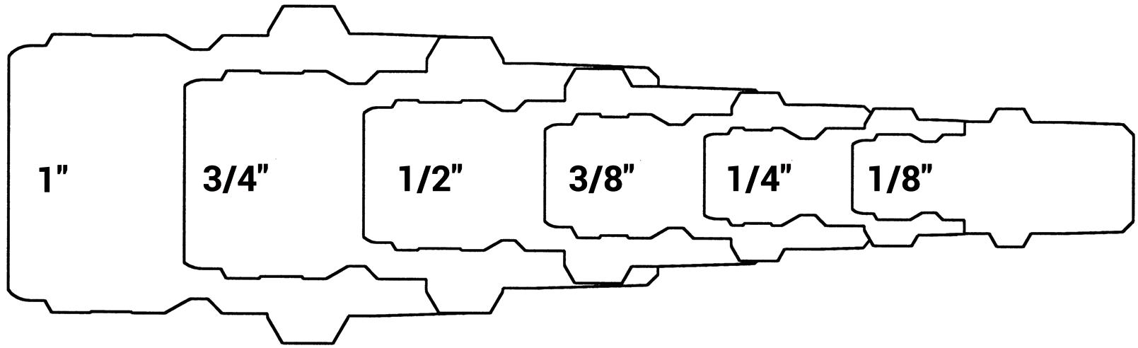
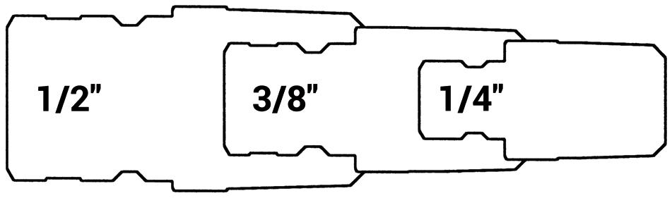
1/2"
EA-Series
CM-Series
Large E-Series 2" 1-1/2" 1-1/4"
Be Safe When Selecting Quick Couplings

All quick disconnect couplings should be viewed as potential hazards that can cause property damage, personal injury or even death if used or installed improperly. Improper use includes selecting a product unsuitable for your application, installing or using the product incorrectly, and/or ignoring signs of imminent failure or misuse. Failure may result in explosive propulsion of components, rapid expulsion of hazardous media, and failure or unintentional movement of a fluid-powered component.
Proper Selection of Quick Disconnect Couplings
The very properties that make a compressed media useful in almost every area of modern life can also make it dangerous when mishandled. Dixon quick disconnect couplings have been carefully engineered to meet specific industry requirements while maintaining abundant safety margins. If quick disconnect couplings are not used in the correct applications or are incorrectly applied, accidents and downtime can result. It is up to the end user to inform the distributor of the application and pressures involved when ordering quick disconnect couplings, and it is up to the distributor to supply the right coupling for the application.
The use of S.T.A.M.P.E.D. will help in the proper selection of quick disconnect coupling products. When in doubt, Dixon will provide information, including test results (if available), coupling recommendations, and other data to help resolve quick disconnect coupling related issues.
S.T.A.M.P.E.D. Questions and Selection Process
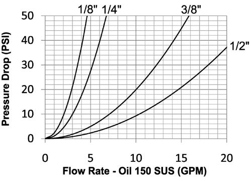
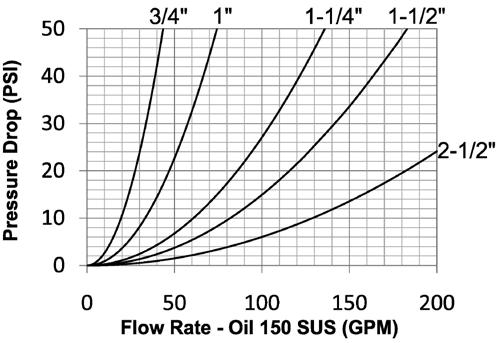
Couplings should be selected to handle the flow and pressure requirements of the system. Excessive pressure drop will result in restricted flow, slower actuation, higher fluid velocity, heat generation, and eventually a breakdown of fluids, seals, and components.
1. What size coupler is required?
2. What is the maximum allowable pressure drop for the application?
3. Are there any size restrictions due to a 'tight-spot' installation?
Media and ambient temperatures must be limited to the specific operating parameters of the selected sealing materials. Excessive cold will reduce sealing capability, while excessive heat can cause the premature breakdown of body and valve seals.
1. What is the media/fluid temperature?
2. What is the ambient temperature?
3. Are there any 'flash' heat or fire sources near the connection?
Quick coupling interchangeability needs to be closely reviewed. There are several instances where non-interchangeable couplers and plugs may connect. This is very dangerous and these couplings should never be pressurized. Be sure to match like series couplers and plugs.
1. Is an industry interchange coupler required?
2. What are the functional requirements of the coupling?
3. Have there been any problems with other couplings in this application?
Quick disconnect couplings are available with a variety of body materials and seal options. Exposure to harsh and corrosive operating environments may reduce service life. Several quick couplings spill fluid upon disconnection, which may be a safety concern.
1. Which seal and body materials are compatible with the system fluid?
2. Is air inclusion, system contamination, or fluid loss a concern?
3. Is this fluid dangerous to the operator?
During the selection process, the published working pressure of the coupling must be equal to or greater than the maximum system pressure. Surge pressures in a fluid power system, higher than the rated pressure, will shorten the service life of the coupling.
1. Is the pressure 'static' or 'dynamic'?
2. What is the maximum operating pressure required for the application?
3. Are there any pressure spikes in the system?
Many end configurations are available and each one has specific operating parameters. For example, the working pressure of couplings utilizing hose barb or collar hose barb end connections may be dramatically reduced. If in doubt, test under controlled conditions for suitability to the application.
1. What end configuration and size is required? (male threaded, female threaded, or hose barb)
2. Does the chosen end configuration support the application parameters and system pressure?
3. What is the ideal valving configuration? (single shut-off, double shut-off, or unvalved)
Forgotten or missed application details can cause a failure if not properly addressed. Be meticulous in the assessment of your application to ensure that all parameters are considered in the selection of the proper quick disconnect coupling.
1. Are there any side-load, vibration, or swivelling problems associated with the application?
2. Does the coupling require a safety sleeve-lock mechanism?
3. Are there any environmental concerns that need to be addressed?
Quick disconnect couplings can fail without warning. Prior to the operation of quick coupling products, be sure to inspect and replace worn out fittings and safety devices. If a leak is detected during operation, release the pressure from the circuit before investigating the cause of the fluid leak. Do not use your fingers or skin to check for leaks. High-pressure leaks of fluids can easily penetrate the skin and can cause serious injury or death.
Safe Quick Coupling Practices
1. Always wipe the coupling cavities and faces clean before connecting a coupling.
2. Connect coupling before installation to ensure that it works properly.
3. Always check the body seals before connecting a coupling.
4. Shut off power source before connecting a coupling.
5. Always install a safety check valve on a pneumatic line and/or compressor.
6. Always use a safety cable on large air lines (1/2" lines and larger).
7. Always use a whip hose on hydraulic or air tools.
8. Use dust caps or plugs when couplings are not in use.
9. If the locking sleeve is inoperable, check the safety lock.
10. Wear eye protection while connecting or disconnecting a coupling.
Unsafe Quick Coupling Practices
1. Never hit coupling valves to release trapped pressure.
2. Never leave couplings in the path of moving equipment.
3. Never use couplings near a welder, flash heat, or fire/flame sources.
4. Never use API modified sealants or over-apply PTFE tape during installation.
5. Use care if you must install quick couplings onto black iron pipe.
6. Never hit a coupling sleeve with a hammer or blunt object.
7. Never overtighten a coupling connection.
8. Never rotate a quick disconnect coupling under pressure.
9. Do not over-pressurize quick disconnect couplings.
10. Never use a hose with a quick disconnect coupling to lift a tool.
OSHA Regulations Ensure Operator Safety
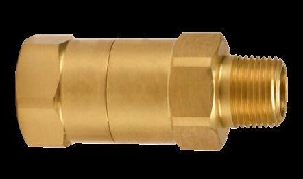
Standard - 29 CFR, 1926.302 (partial):
(b)(1) Pneumatic power tools shall be secured to the hose or whip by some positive means to prevent the tool from becoming accidentally disconnected.
(b)(2) Safety clips or retainers shall be securely installed and maintained on pneumatic impact (percussion) tools to prevent attachments from being accidentally expelled.
(b)(4) Compressed air shall not be used for cleaning purposes except where reduced to 30 PSI and then only with effective chip guarding and personal protective equipment which meets the requirements of Subpart E of this part. The 30 PSI requirement does not apply for concrete form, mill scale, and similar cleaning purposes.
(b)(5) The manufacturer’s safe operating pressure for hoses, pipes, valves, filters, and other fittings shall not be exceeded.
(b)(6) The use of hoses for hoisting or lowering tools shall not be permitted.
(b)(7) All hoses exceeding 1/2" inside diameter shall have a safety device at the source of supply or branch line to reduce pressure in case of hose failure.
Standard - 29 CFR, 1926.603 (partial):
(a)(9) Steam hose leading to a steam hammer or jet pipe shall be securely attached to the hammer with an adequate length of at least 1/4" diameter chain or cable to prevent whipping in the event the joint at the hammer is broken. Air hammer hoses shall be provided with the same protection as required for steam lines.
(a)(10) Safety chains, or equivalent means, shall be provided for each hose connection to prevent the line from thrashing around in case the coupling becomes disconnected.
The regulations may be viewed in full on the OSHA website, osha.gov. Please check the website for updates.
Safety King Cable®
Safety Check Valves
Be Safe When Installing Quick Couplings
All quick disconnect couplings should be viewed as potential hazards that can cause property damage, personal injury, or even death if used or installed improperly.
Couplings should be installed in a location that will allow easy operation of the coupling and accessibility for all necessary installation tools. Care should be given to consider operator safety, especially if spillage upon disconnection could result in fluid ignition or skin and eye irritation.
Only apply wrenches to the hex or machined wrench flats that are provided for assembly purposes, nowhere else. Never clamp on the sleeve of the coupler or the nose of the plug as this will cause distortion and/or damage.
Finally, always test quick coupling installations before putting into operation by pressurizing the unit to working pressure in an enclosed/protective environment.
Installation of Tapered Thread Connections (NPTF)
The seal for NPTF threads is created by the metal-to-metal contact between the roots and crests of the male and female threads. Using too much PTFE tape or pairing liquid sealant with PTFE tape may cause distortion, poor thread engagement, or cracking of the coupling during assembly.
The total number of tapered threads engaged should be between 3-1/2 to 6. Any number of threads outside this range may indicate either under-or over-tightening of the joint or out-of-tolerance threads. After assembly of an NPTF thread connection, always proof-test the connection before operating the system. If the joint proves to be inadequately tightened during proof-pressure testing, tighten it further in 1/8 turn increments until a reliable seal is attained. (Do not exceed 3 turns from finger tight (TFFT)).
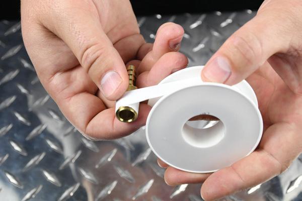
Apply 1-1/2 to 2 wraps of PTFE tape, starting one or two threads from the lead edge, in a clockwise direction. For 316 stainless steel, be sure to use stainless grade tape.
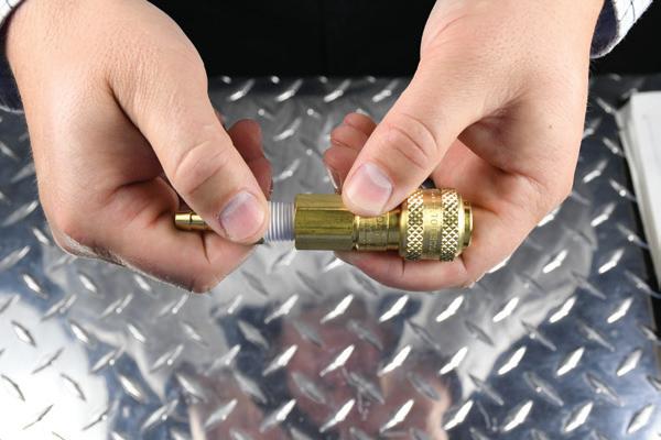
Finger tighten the connection and create a reference mark on the hex of the hose end/adapter and the coupling. This mark will help identify the number of revolutions during the next step in the procedure.
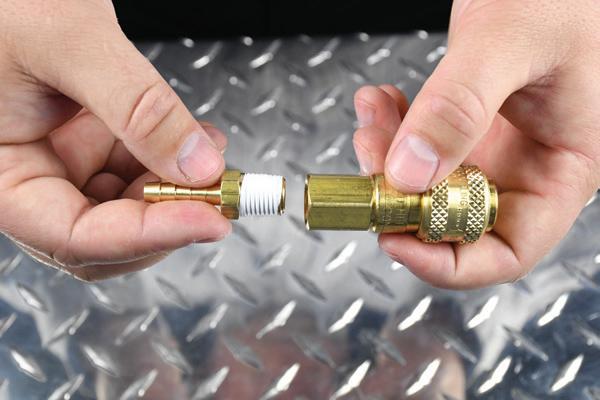
Check threads to make sure there is no obvious damage on either half and that tape is properly installed. Align male and female threaded connections and carefully begin threading the two halves together.
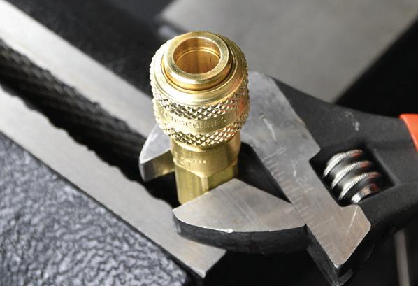
With even and smooth force applied, wrench tighten according to the TFFT values listed below. DO NOT OVERTIGHTEN.
1 2
Be Safe When Installing Quick Couplings
Installation of O-ring Boss (ORB) Connections
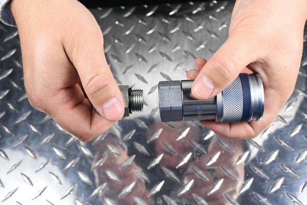
Lightly lubricate the O-ring on the adapter and thread it into the coupling. Hand-tighten, ensuring that the O-ring is not pinched during installation.
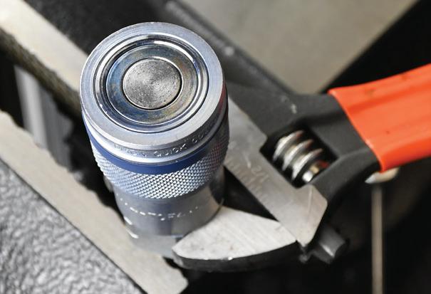
Wrench tighten the connection to the appropriate torque specification, as shown in the chart below.
Installation of 37° Flare (JIC) Connections
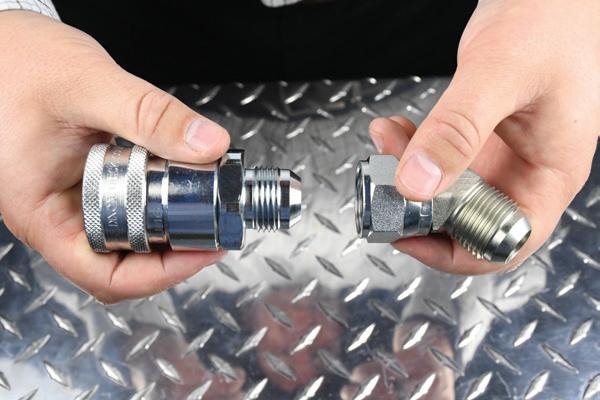
Lightly lubricate the flare on the adapter and thread it into the coupling. Hand-tighten, ensuring that the flare is seated correctly during installation.
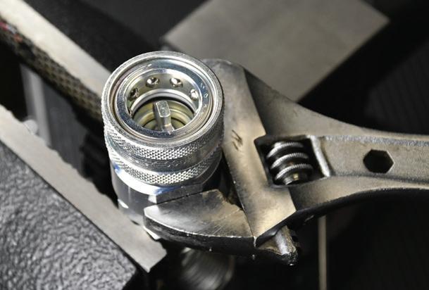
Wrench tighten the connection to the appropriate
specification, as shown in the chart below.
Be Safe When Installing Quick Couplings
Installation of Reusable Hose Couplings
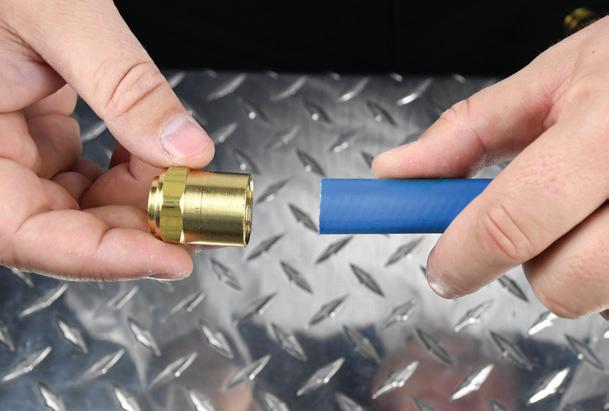
Trim the end of the hose as square as possible.
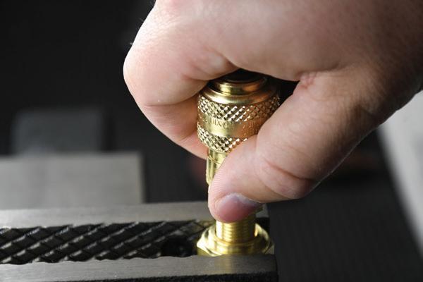
Apply lubricant sparingly to the reusable barb before inserting it into the ferrule.
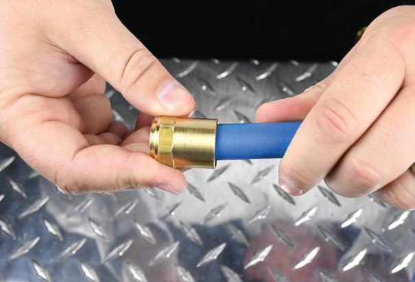
Install ferrule by slipping it onto the end of the hose and twisting it counter-clockwise.
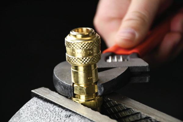
Turn the reusable fitting into the ferrule until coupling is seated against ferrule.
Installation of Push-Loc Hose Connections
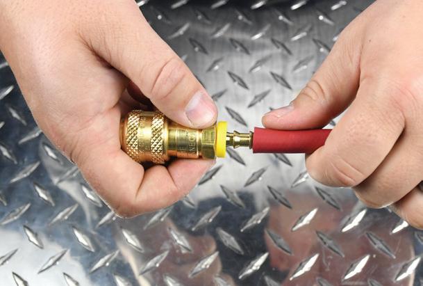
Trim hose end squarely and lubricate the Push-Loc barb and hose. Insert Push-Loc barb into the hose until first barb is inside the hose.
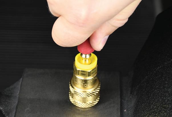
Place the end of the fitting against a flat object and grip the hose one inch from end. Push with a steady force until the end of hose is covered by the yellow plastic cap.
Be Safe When Installing Quick Couplings
Installation of N and P-Series Ferruled Hose Barbs
Note that the charts below are to be used only as a guide and not as a steadfast rule for every coupling application. In some instances, alternative dies and crimped dimensions must be employed. Hoses, as well as couplings, react differently during crimping. This is due to the fact that there are variances in hose constructions for hose with similar dimensions. Some variables are: textile braid versus wire braid, hardwall versus softwall, presence or lack of internal spiral wire as well as differences in hose covers. In addition, the outer diameter of the hose tends to fluctuate from end to end and production lot to production lot. With this in mind, we suggest that you measure the hose O.D. and maintain accurate records for each coupling application.
Installation of Light-Duty Ferrules
Fluid Compatibility Guide
The following chart is intended only as a guide in selecting various elastomers and metals for use with fluids to be conveyed through Dixon quick disconnect couplings. This list does not guarantee suitability for a particular application. Final selection is dependent upon operating pressure, fluid and ambient temperature, concentration of media, duration of exposure, environmental conditions, and frequency of connection and disconnection.
Material
Prefix
Nitrile-N Standard Nitrile -40°F to 250°F -40°C to 121°C
Nitrile-N (MIL-H-5606 Fluids) M- Nitrile -65°F to 275°F -54°C to 135°C
Nitrile-N (Hydrocarbon Fuels) JF- Nitrile -65°F to 160°F -54°C to 71°C
Fluorocarbon Rubber F- FKM -20°F to 400°F -29°C to 204°C
Ethyl Propylene Diene Monomer P- EPDM -65°F to 300°F -54°C to 149°C Neoprene E- Neoprene -45°F to 300°F -43°C to 149°C Silicone S- Silicone -100°F to 350°F -73°C to 177°C
Fluorosilicone (FVMQ) FS- Silastic® -76°F to 376°F -60°C to 180°C Urethane U- Urethane -40°F to 180°F -40°C to 82°C
Polyurethane UP- Polyurethane -65°F to 212°F -54°C to 100°C
PTFE Encapsulated Silicone TS- TES -100°F to 400°F -73°C to 204°C
PTFE Encapsulated Fluorocarbon TF- TEF -100°F to 400°F -73°C to 204°C
Perfluoroelastomer (Compound 1) K4- Kalrez® 4079 -4°F to 600°F -20°C to 316°C
Perfluoroelastomer (Compound 2) K6- Kalrez® 6375 -4°F to 525°F -20°C to 275°C
Perfluoroelastomer (Compound 3) K7- Kalrez® 7075 -4°F to 620°F -20°C to 327°C
Fluoroelastomer H- Aflas® 23°F to 400°F -5°C to 204°C
Media Name Suggested Seal
Media Name Suggested Seal Media Name Suggested Seal
Acetic Anhydride P- Freon, General E- Mineral Spirits Standard Acetone P- Ferric Hydroxide Standard Nickel Acetate PAcetylene Standard Formaldehyde (50%) P- Nickel Sulphate PAir (To 200°F) Standard Fuel Oils, General Standard Nitrogen, Gas Standard Air (Above 200°F) F- Gasoline Standard Nitrous Oxide Standard Alcohol, Ethyl P- Glycerine (Glycerol) Standard Octane FAlcohol, Methyl Standard Glycols P- Oleum Spirits Standard Alkalis, General Standard Helium Standard OS45 and OS45-1 FAmmonia, Aqueous P- Heptane Standard Oxygen, Non-Breathing FAmmonia, Gas P- Hexane Standard Paint Thinner FAmmonia, Anhydrous P- Hydraulic Oil, Aircraft Standard Paraffin Standard
Ammonia, Hydroxide P- Hydraulic Oil, Petroleum Standard Peanut Oil Standard Aroclor F- Hydraulic Oil, Phosphate P- Pentane Standard Benzene (Benzol) F- Hydrogen Gas Standard Perchloroethylene FBleach Solutions P- Hydrolube Standard Phosphoric Acid (100%) PBrake Fluid, Non-Petro P- Isobutyl Alcohol P- Photographic Solutions PBromine Gas F- Isopropyl Alcohol F- Potassium Acetate PButyl Alcohol Standard Jet Fuel (to 160°F) JF- Propylene F-
Carbon Dioxide, Dry Standard Jet Fuel (above 160°F) F- Propylene Glycol Standard
Carbon Dioxide, Wet Standard Kerosene Standard Silicone Oil Nitrile Carbon Monoxide Standard Lindol P- Steam, General Service H-
Carbon Tetrachloride F- Magnesium Hydroxide F- Stoddard Solvent Standard Cellulube P- Methane Standard Sulphuric Acid (100%) FCreosote F- Methanol Standard Toluene F-
Crude Oil F- Methyl Bromide F- Transmission Fluid (A) Standard
Cutting Oil Standard
Methyl Ethyl Ketone (MEK) P- Trichloroethylene F-
Diesel Fuel Standard MIL-F-81912 (JP-9) P- Turpentine Standard
Diester Lubricants F-
Ethane Standard
Ethanol P-
MIL-H-5606 M1- Vegetable Oil Standard
MIL-H-5806 Standard Water Standard
MIL-H-6083 Standard Water, Distilled Standard
Ethyl Chloride Standard MIL-H-7083 Standard Water, Dionized Standard
Ethylene Glycol P-
Diesel Exhaust Fluid (Def) P-
Mineral Oils Standard Water, Sea P-
Pneumatic Couplings: DF-Series
Materials Interchange Data
• Parker 20-series manual interchange (F-series)
• Parker 30-series automatic interchange (D-series)
• Foster 3, 4, 5, and 6-series
• Hansen 1000, 400, 500 (F-series)
• Hansen 3000, 4000, 5000, 6000 (D-series)
Body Size
• Machined components are manufactured using solid steel, brass, or 303 stainless steel bar stock
• Stainless steel balls, retaining rings, and springs maximize corrosion resistance and extend service life
• Steel componentry is plated using RoHS-compliant trivalent chrome
• Automatic couplers constructed of brass with steel tubular valve as standard (3/8" to 3/4" couplers have steel prong valves)
• 1/4" manual couplers constructed of brass with steel sleeve and steel tubular valve as standard
• 3/8" and 1/2" manual couplers constructed of steel as standard with steel tubular valve
Seal Components
• Nitrile seals are standard, providing a temperature range of -40°F to 250°F (-40°C to 121°C)
Rated Pressure Charts
D-Series Automatic Industrial Interchange (Connected)
F-Series
Technical Specifications
Available Options
Pneumatic Couplings: DF-Series
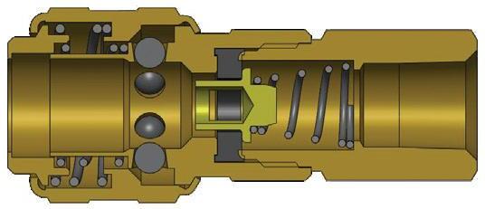
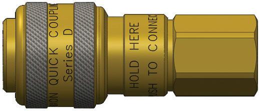
Body Size
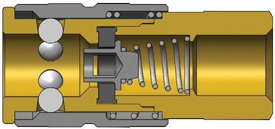
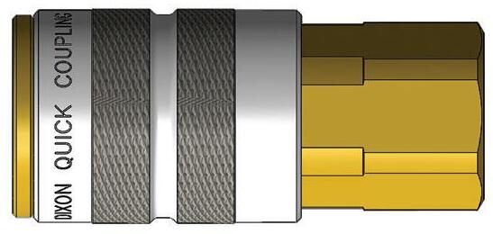
F-Series Manual Industrial Interchange Coupler (Female Threads)
Pneumatic Couplings: DF-Series
Body Size
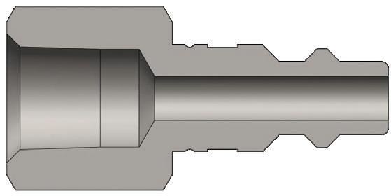
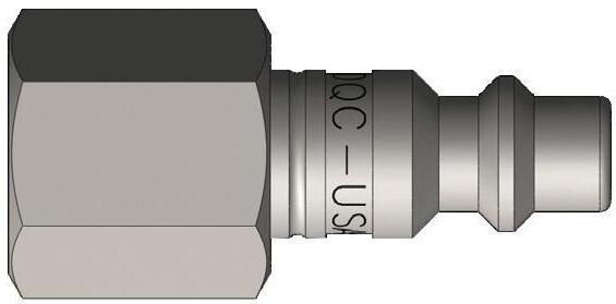
DF-Series Industrial Interchange Plug (Female Threads)
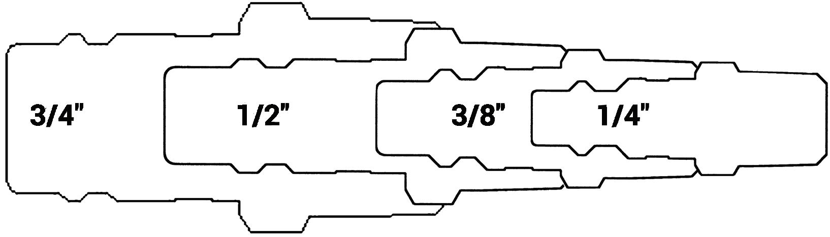
DF Series Pneumatic Profile
Pneumatic Couplings: DF-Series
Body Size
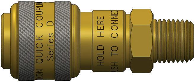
D-Series Automatic Industrial Interchange Coupler (Male Threads)
- 14
It is important to be safe when installing quick disconnect couplings into a pneumatic circuit. Never install a pneumatic coupling directly into an air tool. Use a piece of hose that is at least 18" long between the tool and the coupling to prevent damage to the coupling. To protect the operator, safety devices such as a safety check valve and safety cable should be installed in case there is a hose or coupling failure.
Pneumatic Couplings: DF-Series
Body Size
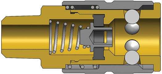
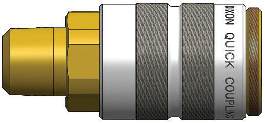
F-Series Manual Industrial Interchange Coupler (Male Threads)
Pneumatic Couplings: DF-Series
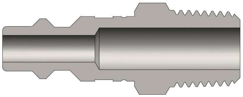
Body Size
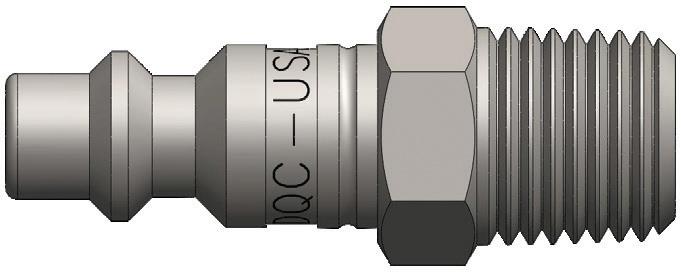
DF-Series Industrial Interchange Plug (Male Threads)
Pneumatic Couplings: DF-Series
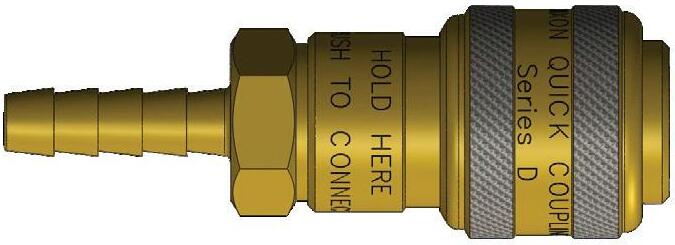
Body Size
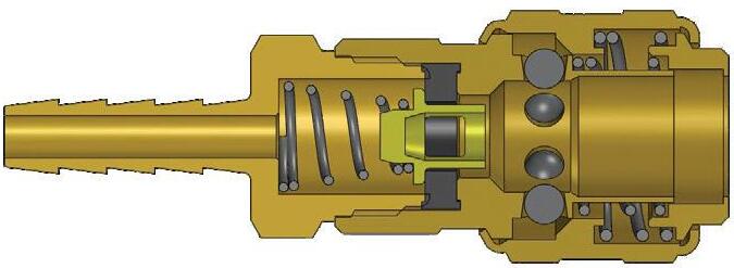
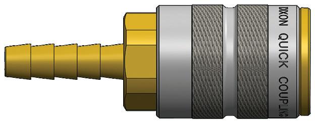
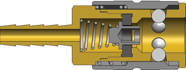
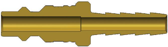
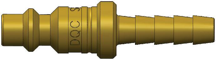
D-Series Automatic Industrial Interchange Coupler (Standard Hose Barb)
Pneumatic Couplings: DF-Series
Body Size
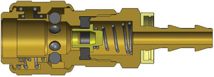
D-Series
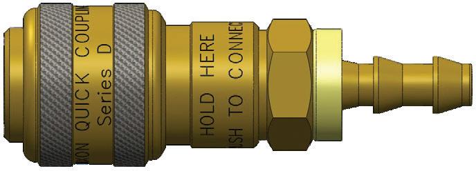
Automatic Industrial Interchange Coupler (Push-Loc Barb)
Pneumatic Couplings: DF-Series
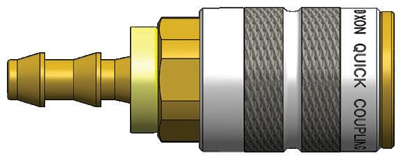
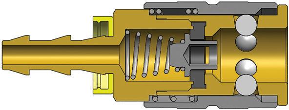
F-Series Manual Industrial Interchange Coupler (Push-Loc Barb)
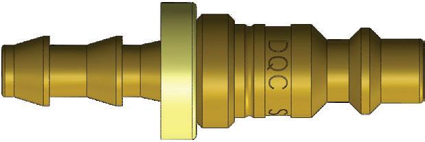
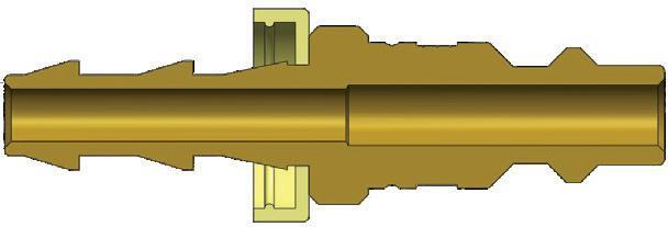
DF-Series Industrial Interchange Plug (Push-Loc Barb)
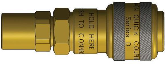
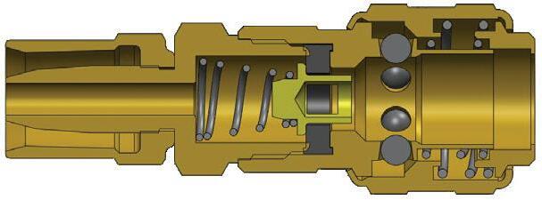
D-Series Automatic Industrial interchange Coupler (Reusable Barb)
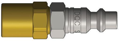
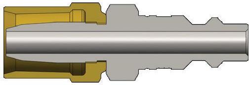
DF-Series Industrial Interchange Plug (Reusable Barb)
Pneumatic Couplings: DF-Series
Automatic Coupler Operation
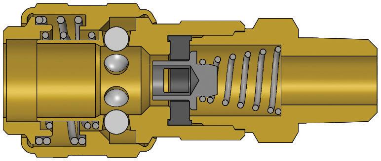
The D-Series automatic coupling has been performing reliably and safely for more than 50 years. This amazing coupler is an inexpensive solution for automatically connecting pressurized air lines.
How To Disconnect
Push sleeve toward plug tip. Do not pull sleeve back.
Push sleeve toward plug.
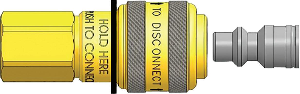
How To Connect
Firmly push plug into socket until you hear a click. Sleeve does not need to be pulled back.
Hold here.
Do not hold forward of black line.
Insert plug and push.
Pneumatic Couplings: J-Series
Interchange Data
• Tru-Flate automotive interchange style
• Parker 10-Series
• Rectus 55KM
• Amflo T-Series Materials
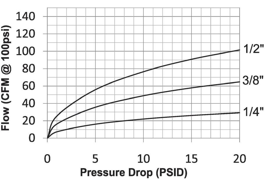
Body Size
Coupler/Steel
• Machined components are manufactured using solid steel or brass bar stock
• Stainless steel balls, retaining rings, and springs maximize corrosion resistance and extend service life
• Steel componentry is plated using RoHS-compliant trivalent chrome
• 1/4" couplers constructed of brass with steel sleeve and steel tubular valve as standard
• 3/8" and 1/2" couplers constructed of steel as standard with steel tubular valves
Seal Components
• Nitrile seals are standard, providing a temperature range of -40°F to 250°F (-40°C to 121°C)
Pressure Chart
J-Series Automotive Interchange (Connected)
Technical Specifications
Operating pressure for couplings utilizing hose barb end connections may be dramatically reduced to that of the hose rating and/or hose end connection combination. Consult hose manufacturer's catalog for hose end connection ratings. If in doubt, test under controlled conditions for suitability to application. Dixon Quick Coupling cannot assume liability for misapplication of production resulting in equipment down-time, lost production, and/or personal injury including death.
Rated
Pneumatic Couplings: J-Series
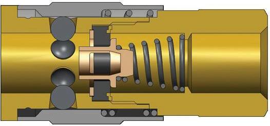
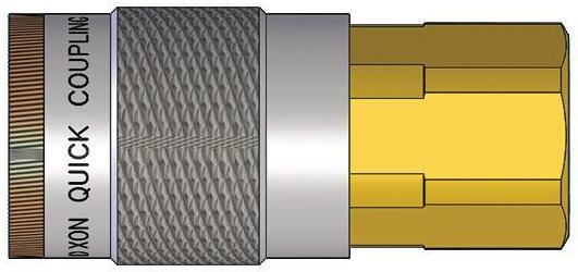
J-Series Automotive Interchange Coupler (Female Threads)
Body Size
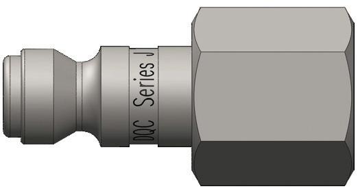
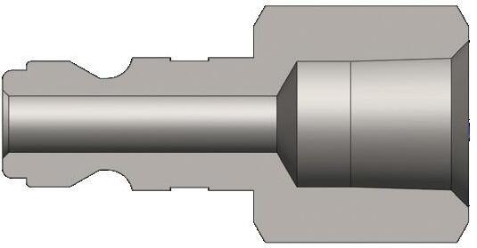
J-Series Automotive Interchange Plug (Female Threads)
Pneumatic Couplings: J-Series
Body Size
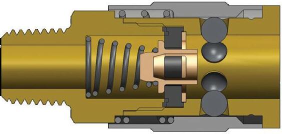
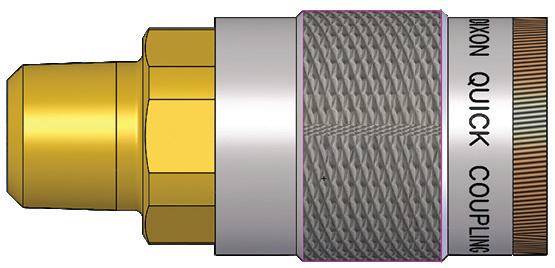
J-Series Automotive Interchange Coupler (Male Threads)
Body Size
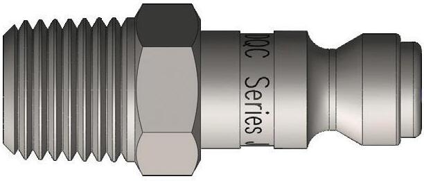
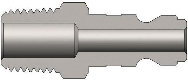
J-Series Automotive Interchange Plug (Male Threads)
Pneumatic Couplings: J-Series
Body Size
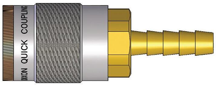
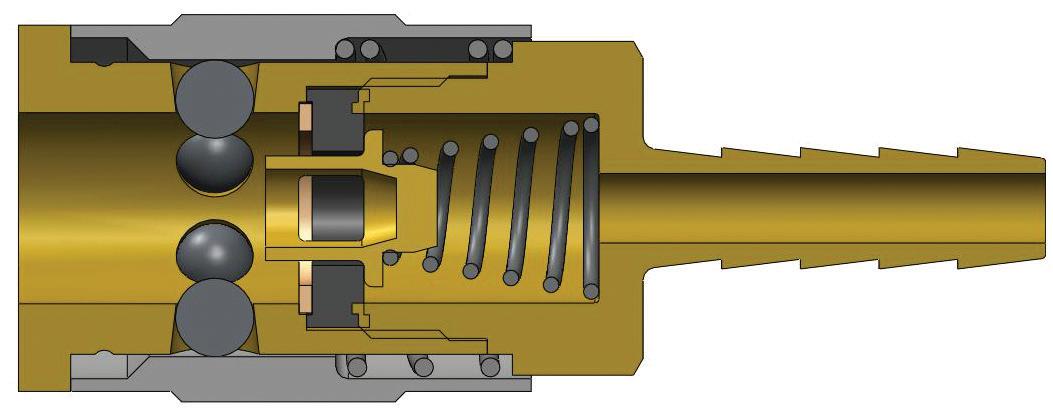
J-Series Automotive Interchange Coupler (Standard Hose Barb)
Body Size
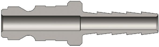
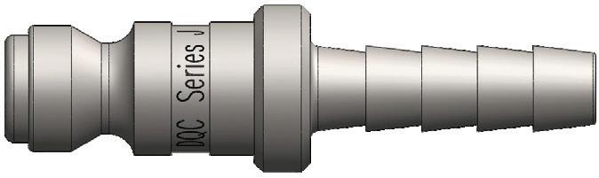
J-Series Automotive Interchange Plug (Standard Hose Barb)
Pneumatic Couplings: J-Series
Body Size
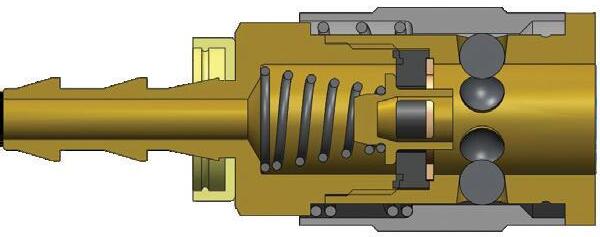
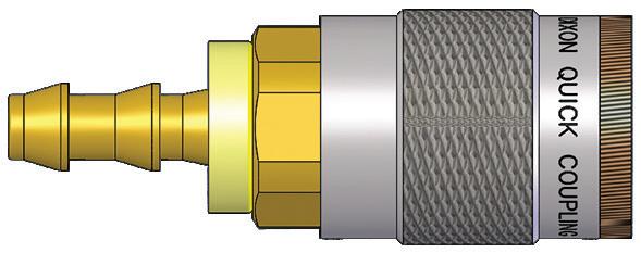
J-Series Automotive Interchange Coupler (Push-Loc Barb)
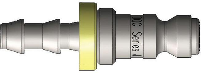
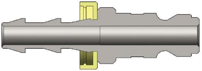
J-Series Automotive Interchange Plug (Push-Loc Barb)
J Series Profiles
Pneumatic Couplings: M-Series
Interchange Data
• ARO 210 (1/4") and ARO 310 (3/8") interchange
• Automatic couplings interchange with ARO 210/310 and Hansen Series 210/310
• Manual couplings interchange with Parker 50-Series and Amflo type B
Materials
• Machined components are manufactured using solid steel or brass bar stock.
• Stainless steel springs; carbon steel balls, retaining rings, and pins
• Steel componentry is plated using RoHS-compliant trivalent chrome
• Automatic couplers constructed of steel
• Manual couplers constructed of brass
Seal Components
• Nitrile seals are standard, providing a temperature range of -40°F to 250°F (-40°C to 121°C)
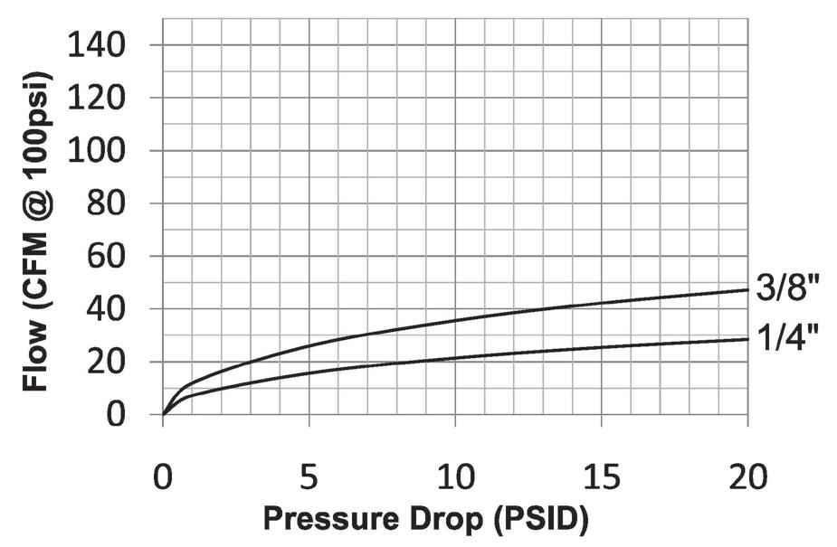
Rated Pressure Chart
M-Series ARO Interchange (Connected)
Body Size
Body Size
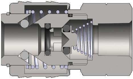
Technical Specifications
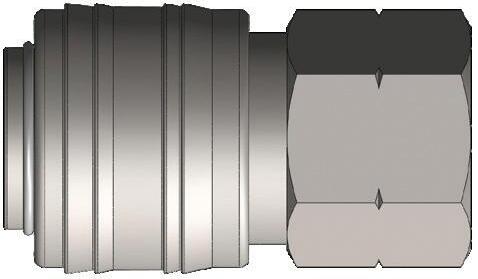
M-Series Automatic ARO Interchange Coupler (Female Threads)
Pneumatic Couplings: M-Series
Body Size
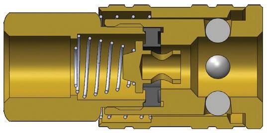
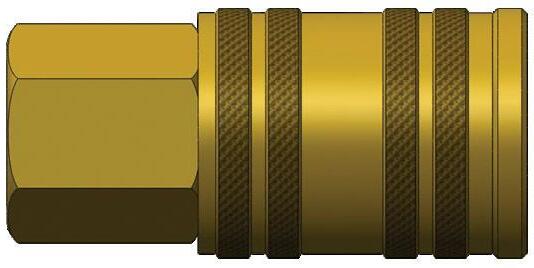
M-Series Manual ARO Interchange Coupler (Female Threads)
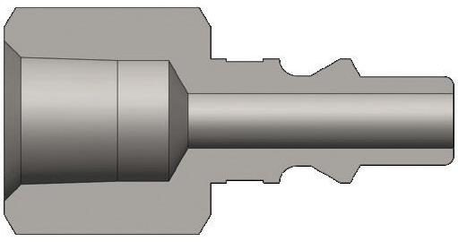
Body Size
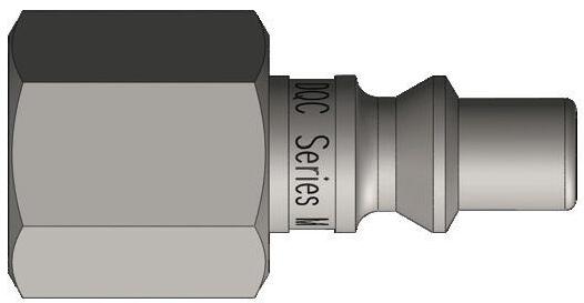
M-Series ARO Interchange Plug (Female Threads)
Body Size
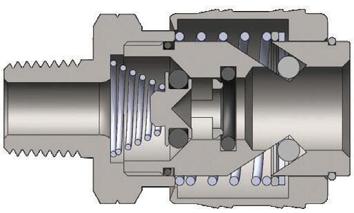
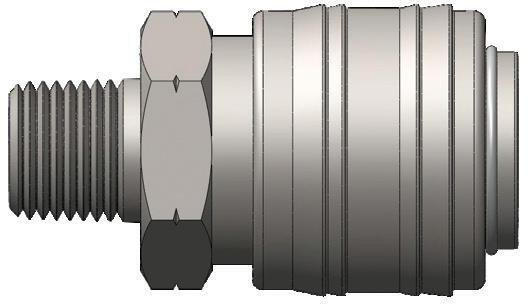
M-Series Automatic ARO Interchange Coupler (Male Threads)
M Series Profiles
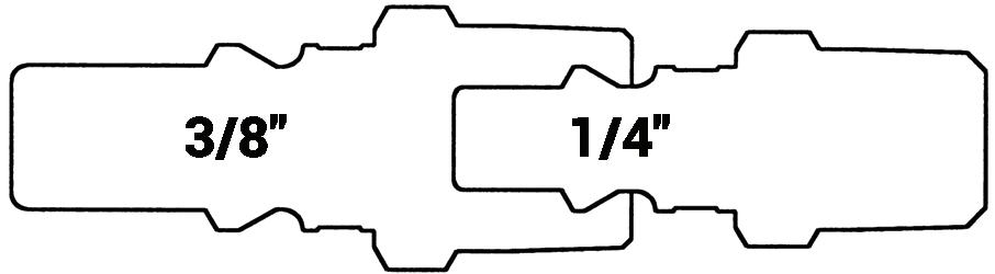
Pneumatic Couplings: M-Series
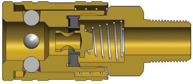
Body Size
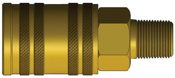
M-Series Manual ARO Interchange Coupler (Male Threads)
Body Size
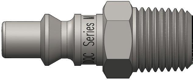
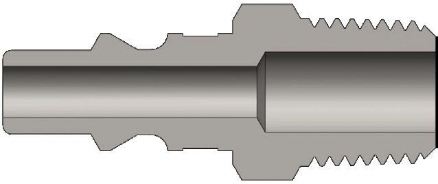
M-Series ARO Interchange Plug (Male Threads)
Body Size
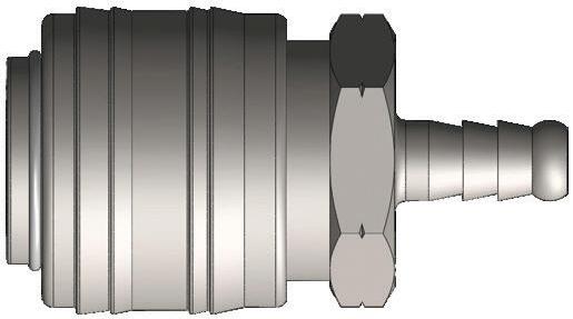
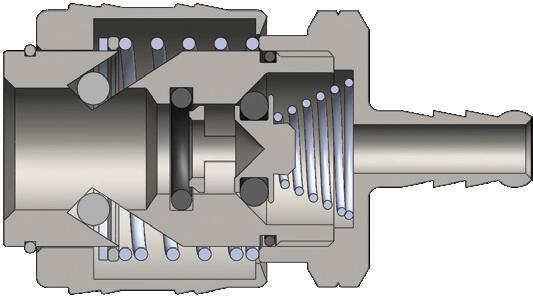
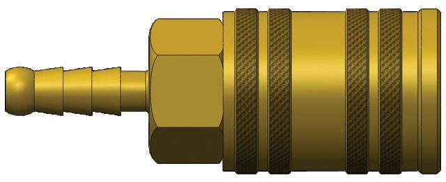
M-Series Automatic ARO Interchange Coupler (Standard Hose Barb)
Pneumatic Couplings: M-Series
Body Size
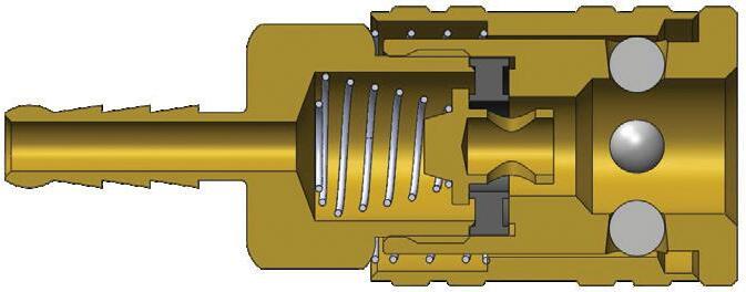
M-Series Manual ARO Interchange Coupler (Standard Hose Barb)
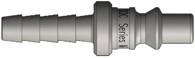
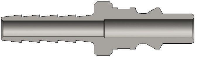
M-Series ARO Interchange Plug (Standard Hose Barb)
Body Size
Body Size
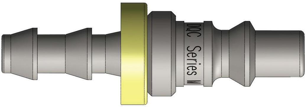
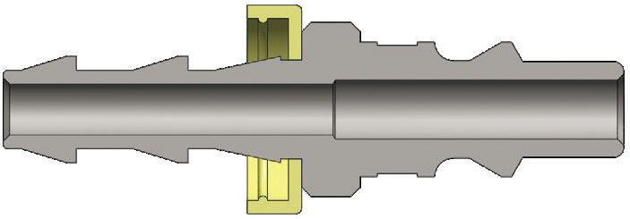
M-Series ARO Interchange Plug (Push-Loc Barb)
It is important to be safe when installing quick disconnect couplings into a pneumatic circuit. Never install a pneumatic coupling directly into an air tool. Use a piece of hose that is at least 18" long between the tool and the coupling to prevent damage to the coupling. To protect the operator, safety devices such as a safety check valve and safety cable should be installed in case there is a hose or coupling failure.
Pneumatic Couplings: CJ-Series
Interchange Data
• European High-flow Interchange
• 1/4" interchanges with Coilhose Megaflow, CEJN 320, and Rectus 25KA/26KA
• 3/8" interchanges with Rectus 27KA and CEJN 410
Materials
• Machined components are manufactured using solid steel or brass bar stock
• Stainless steel springs, carbon steel balls and retaining rings
• Steel componentry is plated using RoHS-compliant trivalent chrome
Seal Components
• Nitrile pneumatically energized seals are standard, providing a temperature range of -40°F to 250°F (-40°C to 121°C)
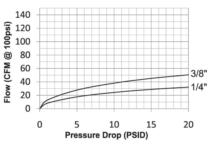
Rated Pressure Chart
CJ-Series European High-Flow Interchange (Connected)
Body Size
Brass Coupler/Steel Plug Brass Coupler/Plug
Body Size
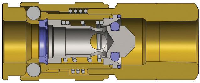
Technical Specifications
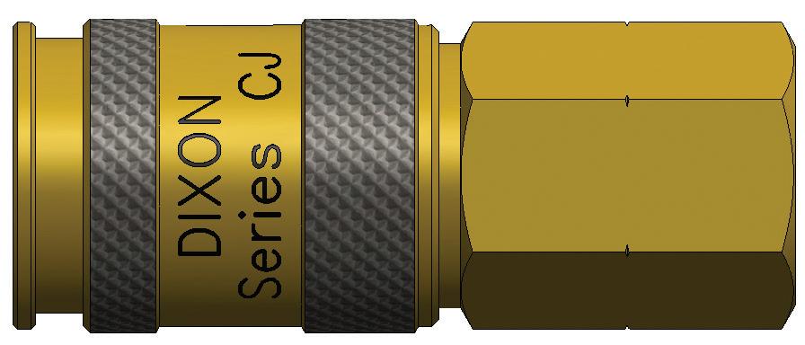
CJ-Series European Interchange Coupler (Female Threads)
Pneumatic Couplings: CJ-Series
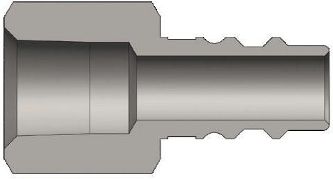
Body Size
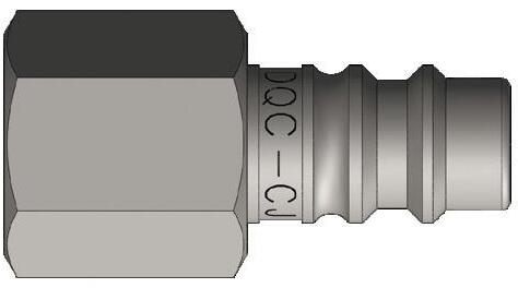
CJ-Series European Interchange Plug (Female Threads)
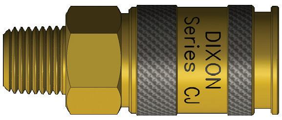
Body Size
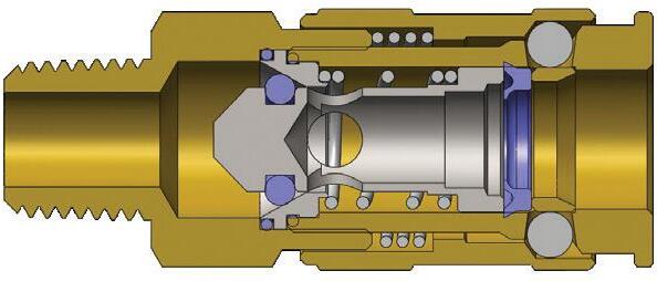
CJ-Series European Interchange Coupler (Male Threads)
Pneumatic Couplings: CJ-Series
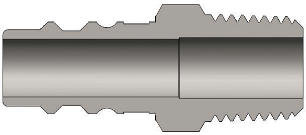
Body Size
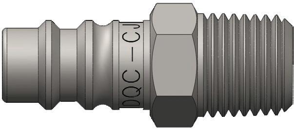
CJ-Series European Interchange Plug (Male Threads)
CJ Series Profiles
Pneumatic Couplings: SHD-Series
Interchange Data
• Schrader Twist-Lock Interchange
• Parker Twist-Lock, Foster SHD
• Tomco TL-Series
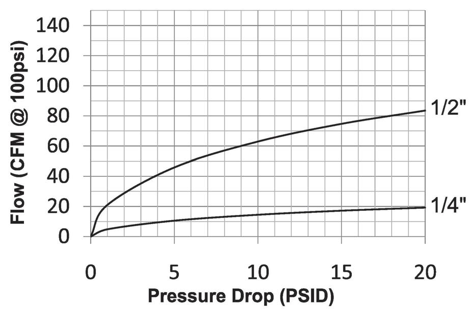
Body Size
Materials
• Machined components are manufactured using solid steel, brass, or aluminum bar stock
• Stainless steel toggle-pawls and springs, carbon steel retaining rings
• Steel componentry is plated using RoHS-compliant trivalent chrome
• Adapter components are constructed of brass
• Sleeves are constructed of steel
Seal Components
• Nitrile seals are standard providing a temperature range of -40°F to 250°F (-40°C to 121°C)
Rated Pressure Chart
SHD-Series Twist-Lock Interchange (Connected)
Coupler/Steel Plug
Technical Specifications
Body
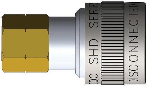
Body Size
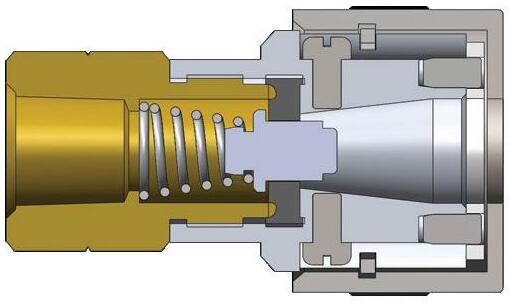
SHD-Series Twist-Lock Interchange Coupler (Female Threads)
Pneumatic Couplings: SHD-Series
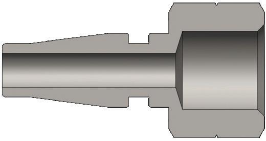
Body Size
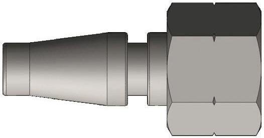
SHD-Series Twist-Lock Interchange Plug (Female Threads)
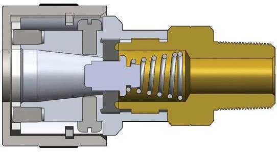
Body Size
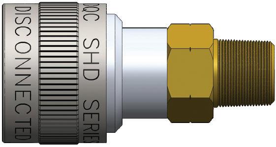
SHD-Series Twist-Lock Interchange Coupler (Male Threads)
Body Size
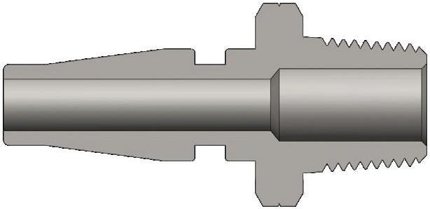
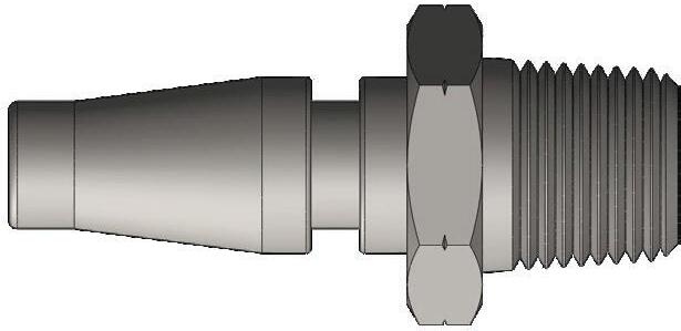
SHD-Series Twist-Lock Interchange Plug (Male Threads)
Pneumatic Couplings: SHD-Series
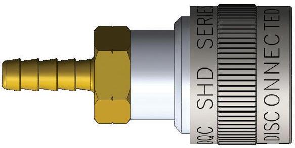
Body Size
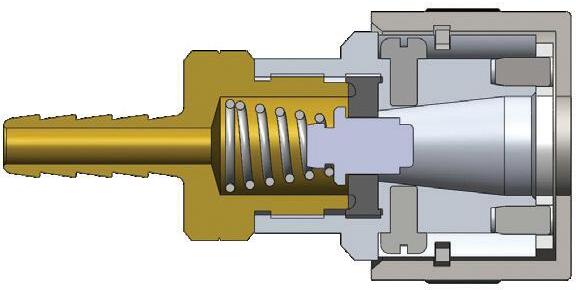
SHD-Series Twist-Lock Interchange Coupler (Standard Hose Barb)
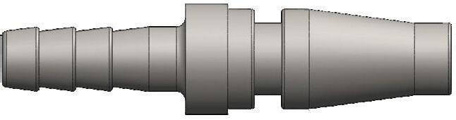
Body Size
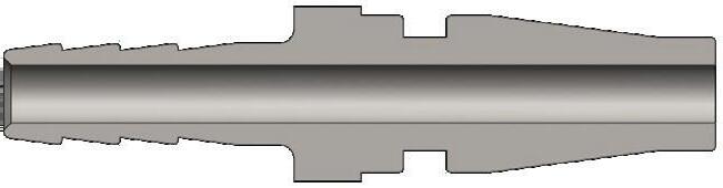
SHD-Series Twist-Lock Interchange Plug (Standard Hose Barb)
SHD Series Profiles
Operating pressure for couplings utilizing hose barb end connections may be dramatically reduced to that of the hose rating and/or hose end connection combination. Consult hose manufacturer's catalog for hose end connection ratings. If in doubt, test under controlled conditions for suitability to application. Dixon Quick Coupling cannot assume liability for misapplication of production resulting in equipment down-time, lost production, and/or personal injury including death.
Pneumatic Couplings: L-Series
Interchange Data
• Lincoln Long-nose Automotive Interchange
• Parker 70-Series, Coilhose Type-17
Materials
• Machined components are manufactured using solid brass or steel bar stock.
• Stainless steel springs, carbon steel balls and retaining rings
• Steel componentry is plated using RoHS-compliant trivalent chrome
Seal Components
• Nitrile seals are standard, providing a temperature range of -40°F to 250°F (-40°C to 121°C)
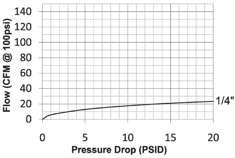
Rated Pressure Chart
Body Size
Body Size
L-Series Lincoln Interchange (Connected) Brass Coupler/Steel Plug
Working Burst
Technical Specifications
Interchange Standards
Functional Parameters U.S. Military U.S. Government International Standards ANSI/NFPA Standards Locking Ball Quantity Air Inclusion
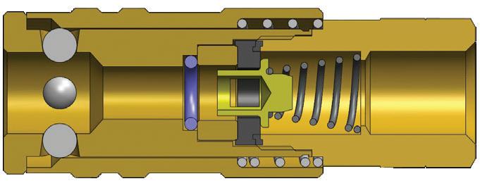
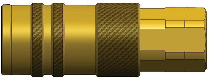
L-Series Lincoln Interchange Coupler (Female Threads)
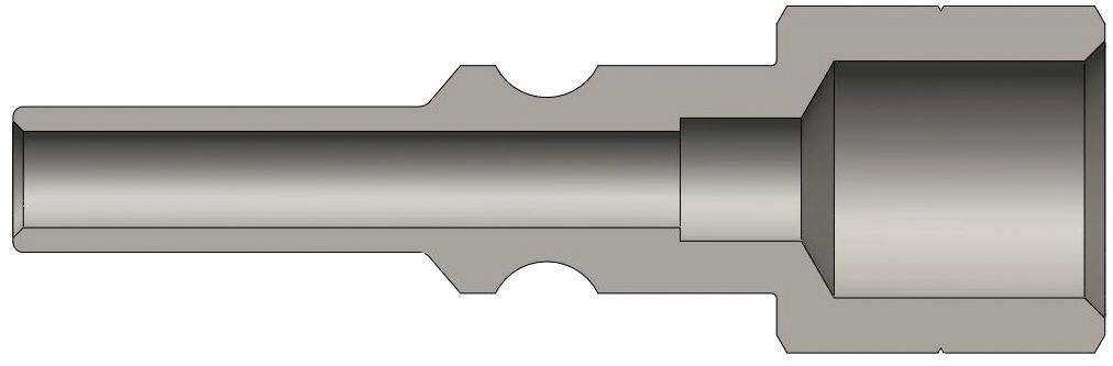
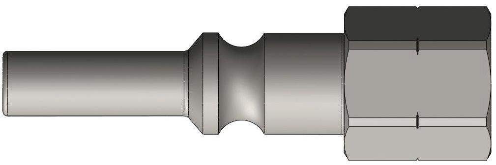
L-Series Lincoln Interchange Plug (Female Threads)
Body Size
Pneumatic Couplings: L-Series
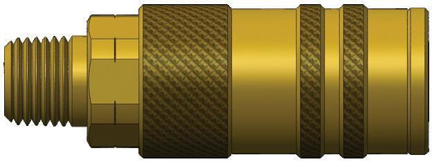
Body Size
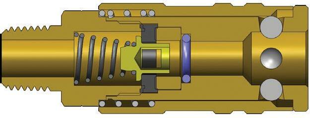
L-Series Lincoln Interchange Coupler (Male Threads)
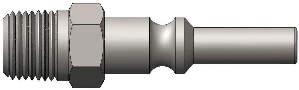
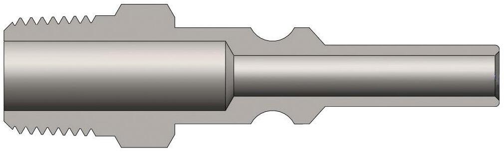
L-Series Lincoln Interchange Plug (Male Threads)
Body Size
L Series Profile
It is important to be safe when installing quick disconnect couplings into a pneumatic circuit. Never install a pneumatic coupling directly into an air tool. Use a piece of hose that is at least 18" long between the tool and the coupling to prevent damage to the coupling. To protect the operator, safety devices such as a safety check valve and safety cable should be installed in case there is a hose or coupling failure.
Pneumatic Couplings: U-Series
Interchange Data
• 2U-Series 6-in-1 (ARO 210, Industrial, Tru-Flate, Lincoln, Italian, and CEJN 320)
• 3U-Series 4-in-1 (ARO 310, Industrial, Tru-Flate, and CEJN 410)
• Parker UC-Series, Hansen Auto-Flo 23, and Coilhose Series UC
Materials
• Machined components are manufactured using solid brass bar stock
• Stainless steel springs, carbon steel balls and retaining rings
• Valve components are machined from solid brass bar stock
Seal Components
• Nitrile pneumatically energized seals are standard, providing a temperature range of -40°F to 250°F (-40°C to 121°C)
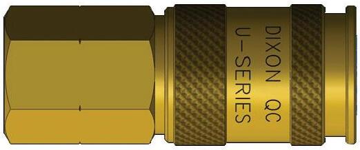
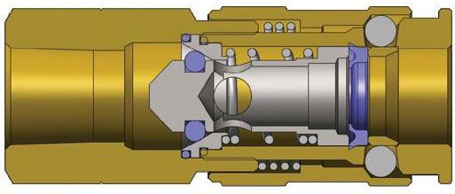
U-Series Automatic Universal Coupler Connected
Body Size
Coupler/Steel DF Plug
Coupler/Steel CJ Plug
Coupler/Steel J Plug
Coupler/Steel M Plug Max. Working Burst
Technical Specifications
Interchange Standards
Body Size
Functional Parameters
Many competitive universal couplings are unable to match the performance capabilities of the Dixon U-Series. Each of the competitive universal couplers only accepts three pneumatic plug styles. Although the universal coupler permits multiple series plugs to mate with one coupler, it is recommended to match like series couplers and plugs. When using a universal coupler, the lower performance rating between the coupler and plug must take precedence.
Dry air: Some pneumatic applications require the pressurized air to be 'dried' to ensure proper operation of equipment and/or application of product (eg. auto body shops). It is best to match like series couplers and plugs in these applications. If it is necessary to use a universal coupler, lube the seal and valve area regularly to ensure reliable service.
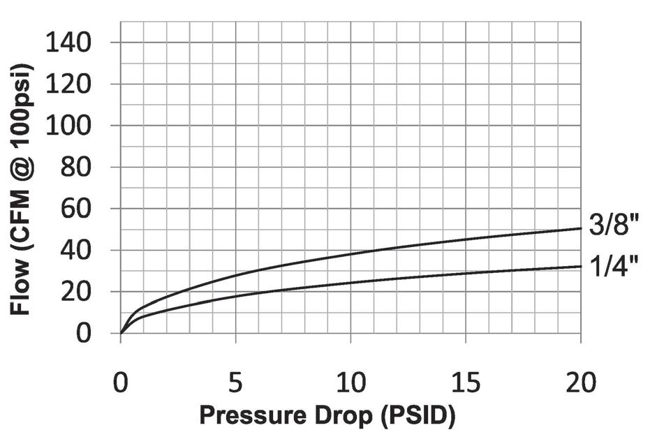
Rated Pressure Chart
Pneumatic Couplings: U-Series
Body Size
U-Series Automatic Universal Coupler (Female Threads)
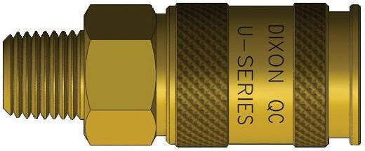
Body Size
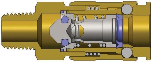
U-Series Automatic Universal Coupler (Male Threads)
Body Size
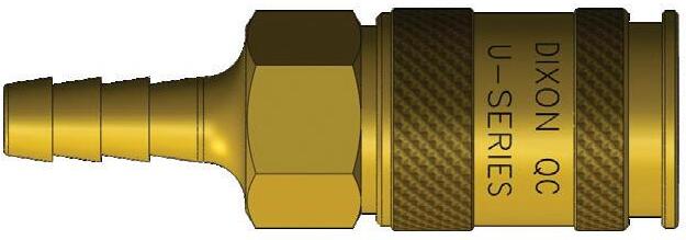
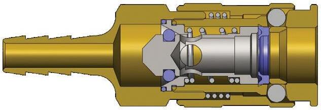
U-Series Automatic Universal Coupler (Standard Hose Barb)
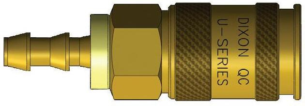
Body Size
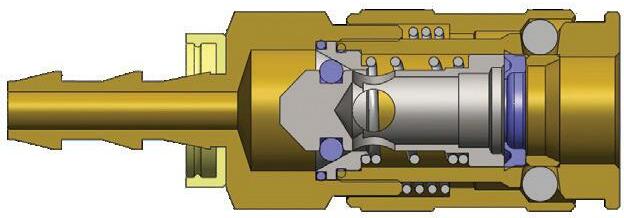
U-Series Automatic Universal Coupler (Push-Loc Barb)
Pneumatic Couplings: Dix-Lock® N-Series
Interchange Data
• Bowes Interchange Bayonet Style
• Interchangeable with Bowes 51000-Series, National Series B, Dix-Lock®, MacDonald Quick-Action, and Campbell Single Lock
Materials
• Machined components are manufactured using solid steel, brass, or 303 stainless steel bar stock. 316 stainless steel available in some versions upon request
• Stainless steel retaining ring and spring maximize corrosion resistance and extend service life
• Steel componentry is plated using RoHS-compliant trivalent chrome
• Dust cap with steel cable lanyard
• Steel plugs have a cast zinc sleeve
• Steel and brass locking version have an aluminum lock ring while the stainless locking version has a stainless lock ring
Seal Components
• Nitrile pneumatically energized seals are standard, providing a temperature range of -40°F to 250°F (-40°C to 121°C)
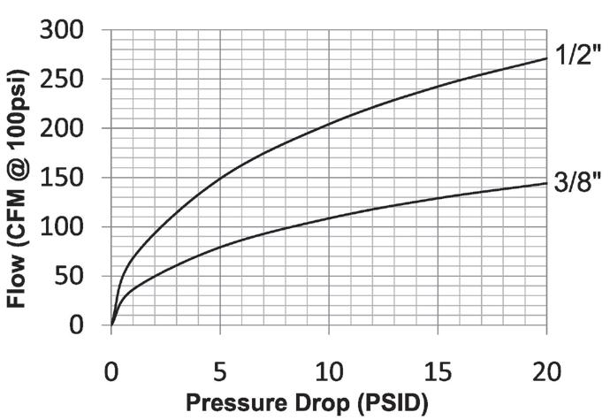
Rated Pressure Chart
Dix-Lock N-Series (Connected)
Technical Specifications Body
It is important to be safe when installing quick disconnect couplings into a pneumatic circuit. Never install a pneumatic coupling directly into an air tool. Use a piece of hose that is at least 18" long between the tool and the coupling to prevent damage to the coupling. To protect the operator, safety devices such as a safety check valve and safety cable should be installed in case there is a hose or coupling failure.
Pneumatic Couplings: Dix-Lock® N-Series
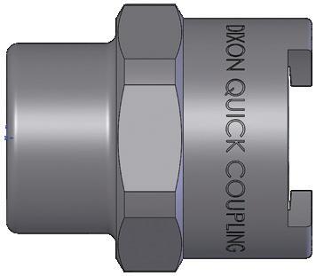
Body Size
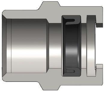
Dix-Lock N-Series Coupler (Female Threads)
Pneumatic Couplings: Dix-Lock® N-Series
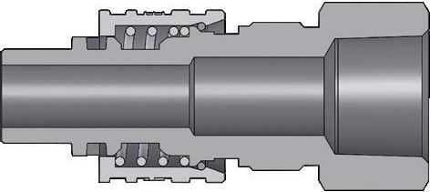
Body Size
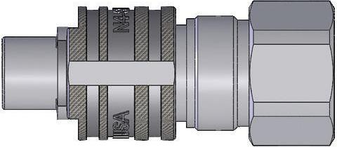
Dix-Lock N-Series Plug (Female Threads)
- 18
- 18
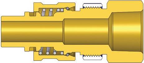
Body Size
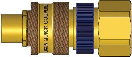
Dix-Lock N-Series Plug with Locking Sleeve (Female Threads)
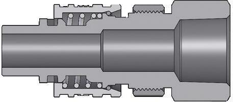
Body Size
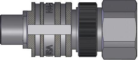
Dix-Lock N-Series Plug with Steel Locking Sleeve (Female Threads)
Pneumatic Couplings: Dix-Lock® N-Series

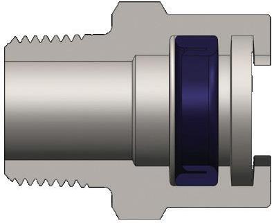
Body Size Dix-Lock N-Series Coupler (Male Threads)
Body Size
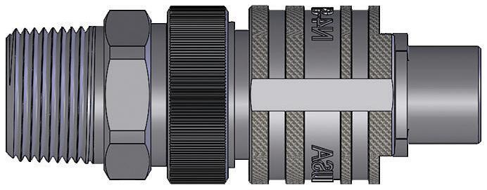
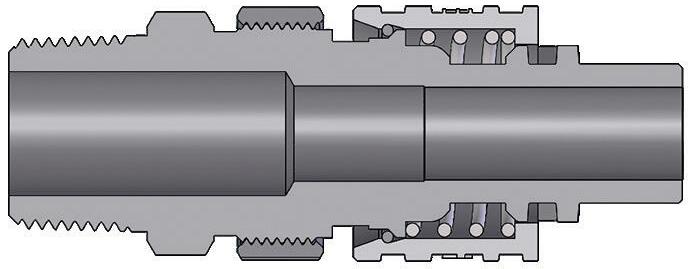
Dix-Lock N-Series Interchange Plug with Steel Locking Sleeve (Male Threads)
Pneumatic Couplings: Dix-Lock® N-Series
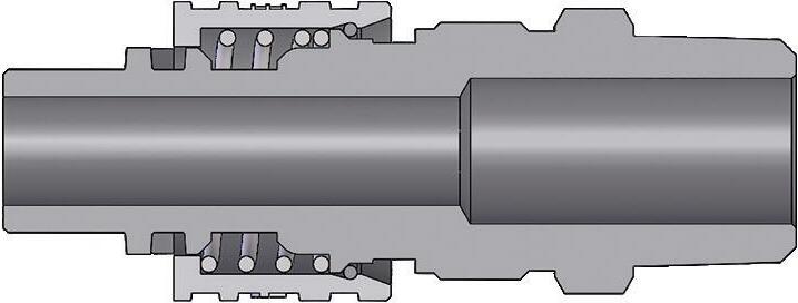
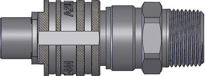
Dix-Lock N-Series Plug (Male Threads)
Body Size
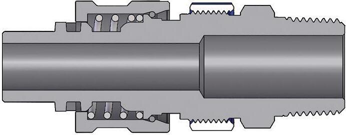
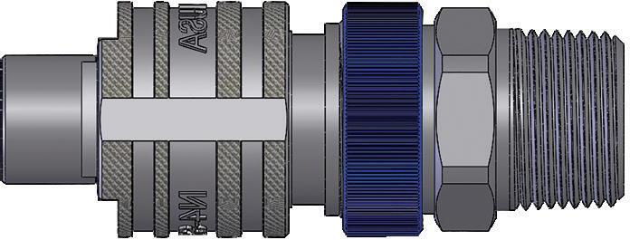
Dix-Lock N-Series Plug with Locking Sleeve (Male Threads)
Pneumatic Couplings: Dix-Lock® N-Series
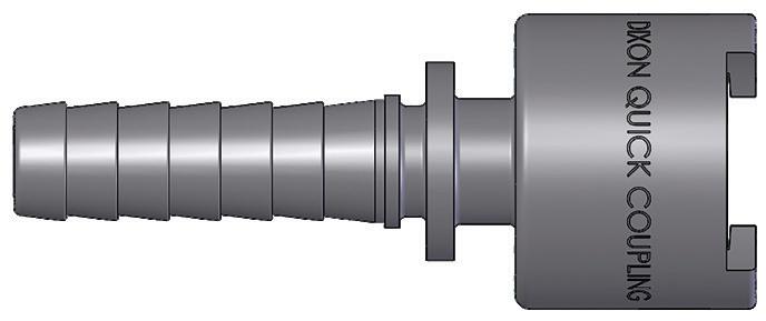
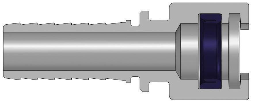
Dix-Lock N-Series Coupler (Hose Barb)
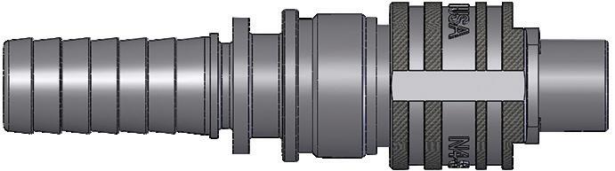
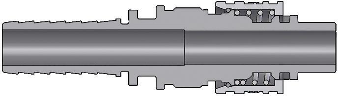
Dix-Lock N-Series Plug (Hose Barb)
Pneumatic Couplings: Dix-Lock® N-Series
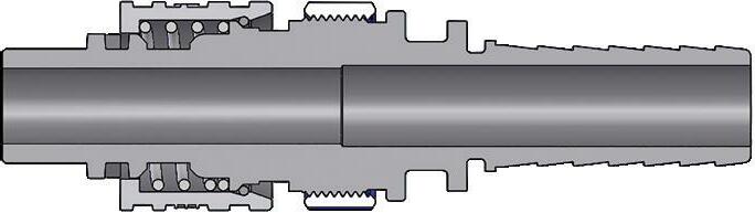
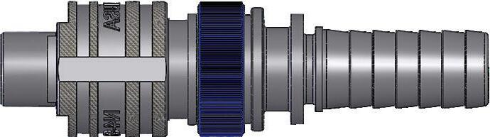
Dix-Lock N-Series Plug with Locking Sleeve (Hose Barb)
Body Size
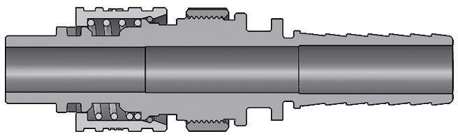
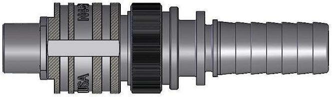
Dix-Lock N-Series Interchange Plug with Steel Locking Sleeve (Hose Barb)
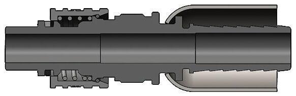
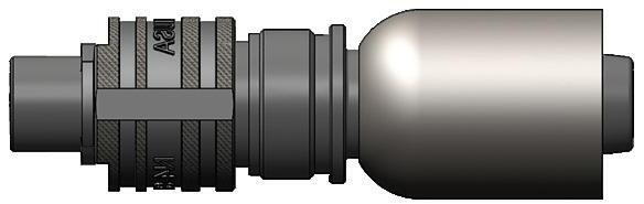
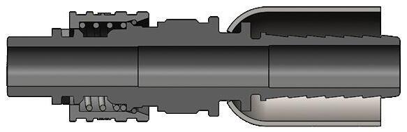
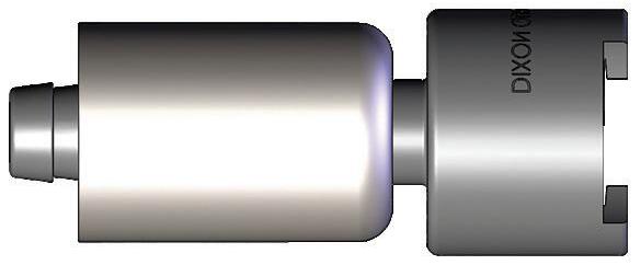
Dix-Lock N-Series Plug with Ferrule (Hose Barb)
Pneumatic Couplings: Dix-Lock® N-Series
Body Size
Body Size
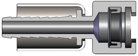
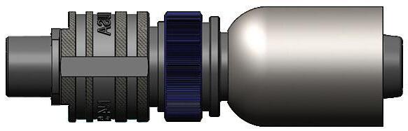
Dix-Lock N-Series Coupler with Ferrule (Hose Barb)
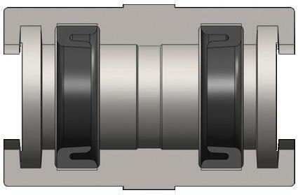
Dix-Lock N-Series Gender-Change Union
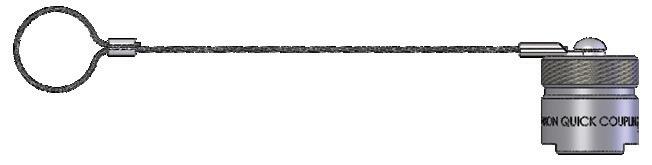
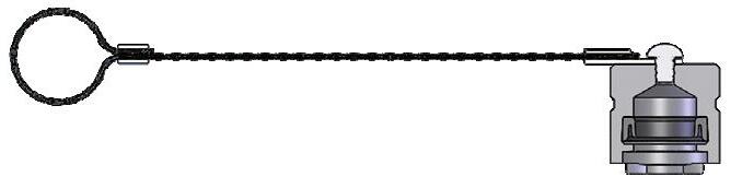
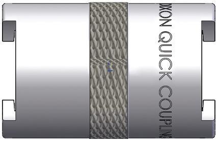
Dix-Lock N-Series Protective Plug Cap
Body Size
Dix-Lock N-Series Replacement Seals
Body Size
Pneumatic Couplings: Dual-Lock P-Series
Interchange Data
• Thor Finger-Lock Interchange
• Interchanges with Thor PHC-Series, National Series A, Dual-Lock, and Campbell Double Lock
Materials
• Machined components are manufactured using solid steel, brass, or 303 stainless steel bar stock
• Stainless steel retaining ring and spring maximize corrosion resistance and extend service life on the 1-piece sleeve; 2-piece sleeve has a phosphor bronze spring
• Steel componentry is plated using RoHS-compliant trivalent chrome
• Steel couplings have a cast zinc sleeve
Seal Components
• Nitrile seals are standard, providing a temperature range of -40°F to 250°F (-40°C to 121°C)
Rated Pressure Chart
Technical
Specifications
Available Options
Pneumatic Couplings: Dual-Lock P-Series
Body Size
Body Size
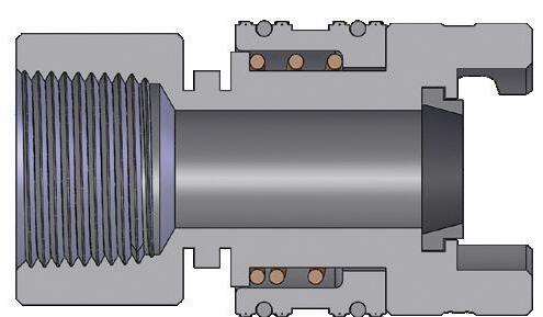
Dual-Lock P-Series Coupler (Female Threads)
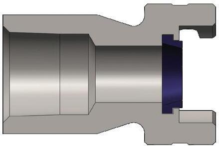
Dual-Lock P-Series Plug (Female Threads)
Pneumatic Couplings: Dual-Lock P-Series
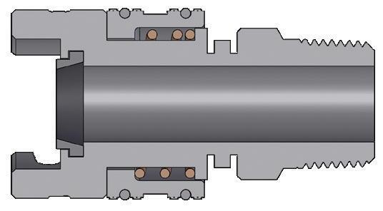
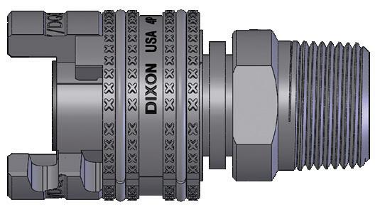
Dual-Lock P-Series Coupler (Male Threads)
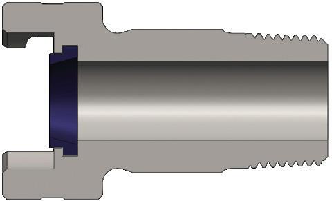
Body Size
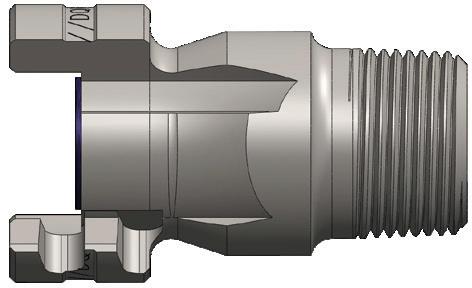
Dual-Lock P-Series Plug (Male Threads)
Body Size
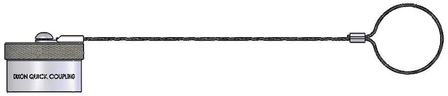
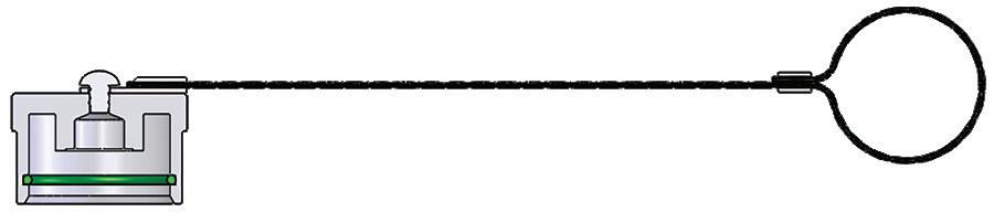
Dual-Lock P-Series Cap Part Detail
Pneumatic Couplings: Dual-Lock P-Series
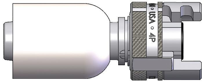
Body Size
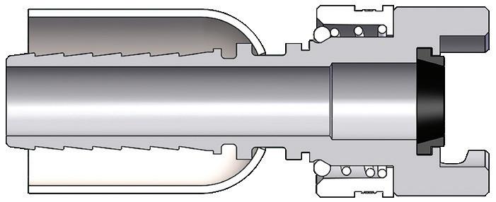
Dual-Lock P-Series Coupler with Ferrule (Hose Barb)
Body Size
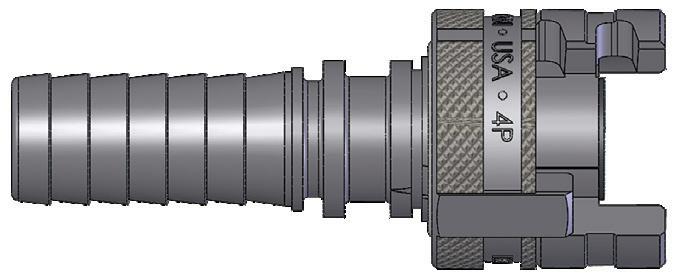
Dual-Lock
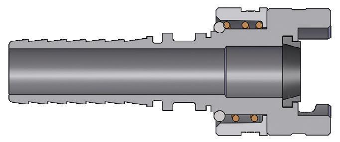
P-Series Coupler (Hose Barb)
Dual-Lock P-Series Replacement
Seals
Body Size
Pneumatic Couplings: NK-Series
Interchange Data
• Japanese Industrial Interchange Pneumatic Coupling
• Nitto Kohki Hi-Cupla 200, Rectus Series 13, and CEJN Series 315
Materials
• Machined components are manufactured using solid steel bar stock
• Stainless steel springs; carbon steel balls and retaining rings
• Steel componentry is plated using chrome-over-nickel plating
Seal Components
• Nitrile seals are standard, providing a temperature range of -40°F to 250°F (-40°C to 121°C)
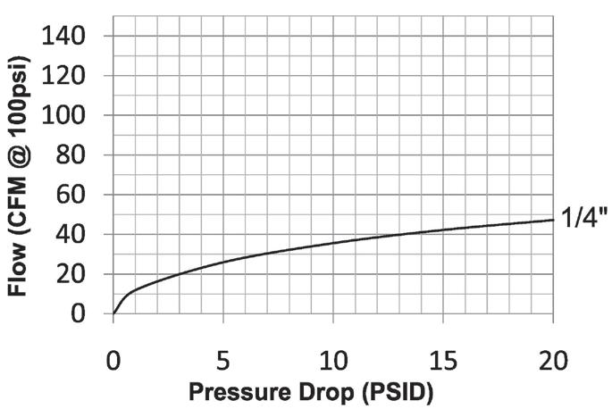
Body Size
Rated Pressure Chart Body Size
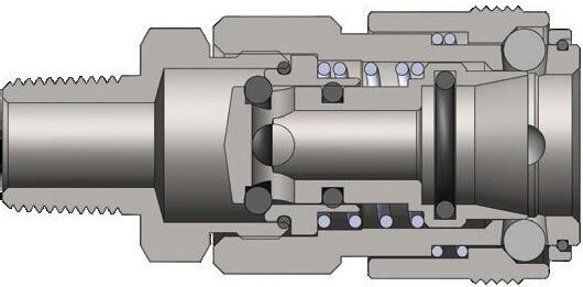
NK-Series Japanese Industrial Interchange (Connected) Coupler/Plug
Standards
Technical Specifications
Parameters U.S. Military U.S. Government International Standards ANSI/NFPA Standards Locking Ball
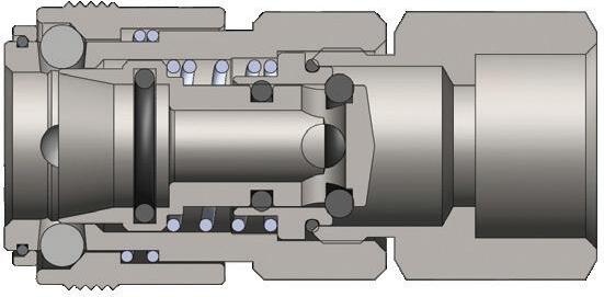
Body Size
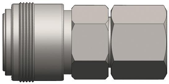
NK-Series Japanese Industrial Interchange Coupler (Female Threads)
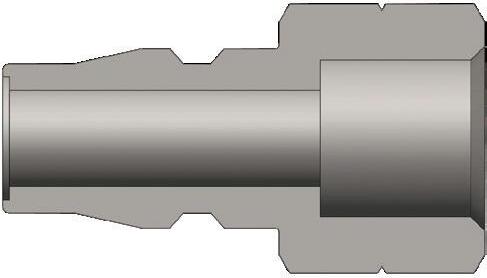
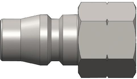
Pneumatic Couplings: NK-Series
Body Size
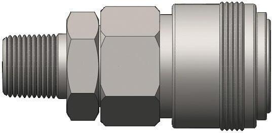
NK-Series Japanese Industrial Interchange Coupler (Male Threads)
Body Size
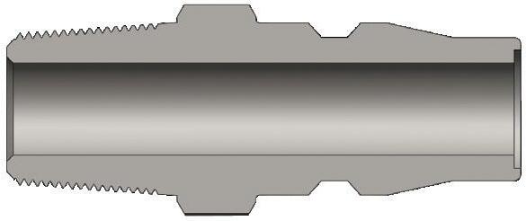
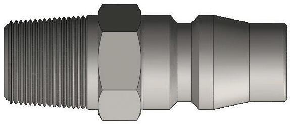
NK-Series Japanese Industrial Interchange Plug (Male Threads)
Body Size
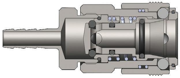
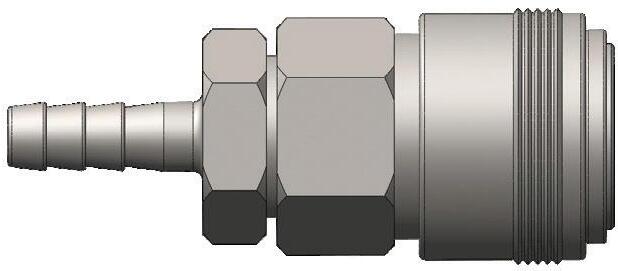
NK-Series Japanese Industrial Interchange Coupler (Hose Barb)
Body Size
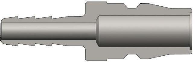
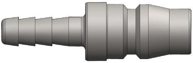
NK-Series Japanese Industrial Interchange Plug (Hose Barb)
Pneumatic Couplings: BR-Series
Interchange Data
• Rectus 21KA, CEJN Series 223
Materials
• Machined components are manufactured using solid brass bar stock
• Stainless steel springs; carbon steel balls and retaining rings
• Machined components are plated with chrome-over-nickel plating
Seal Components
• Nitrile seals are standard, providing a temperature range of -40°F to 250°F (-40°C to 121°C)
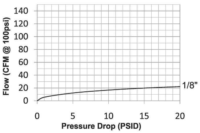
Rated Pressure Chart
Body Size
BR-Series 21-Series Interchange (Connected) Coupler/Plug
Technical Specifications
Body Size Interchange Standards
Functional Parameters U.S. Military U.S. Government International Standards ANSI/NFPA Standards Locking Ball Quantity Air Inclusion Fluid Loss Vacuum
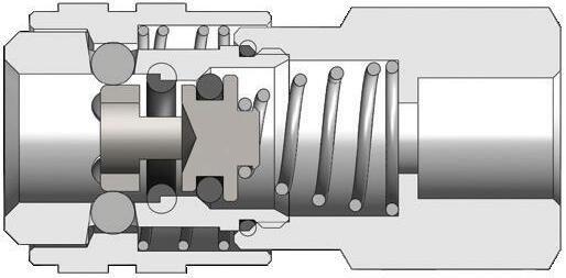
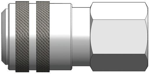
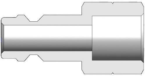
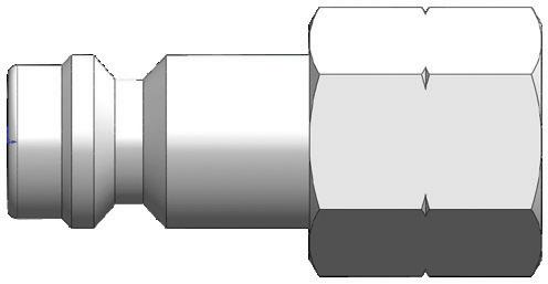
BR-Series 21-Series Interchange Plug (Female Threads)
Pneumatic Couplings: BR-Series
Body Size
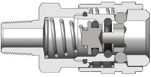
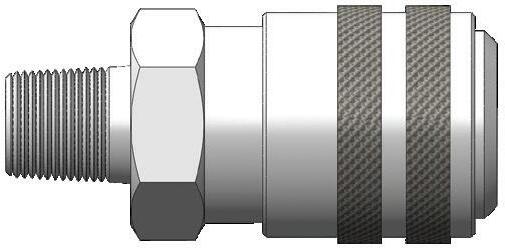
BR-Series 21-Series Interchange Coupler (Male Threads)
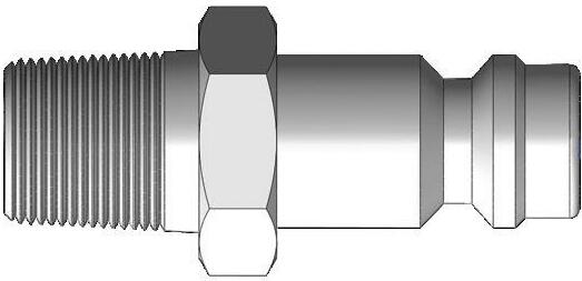
Body Size
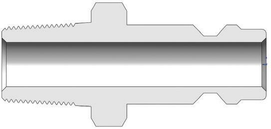
BR-Series 21-Series Interchange Plug (Male Threads)
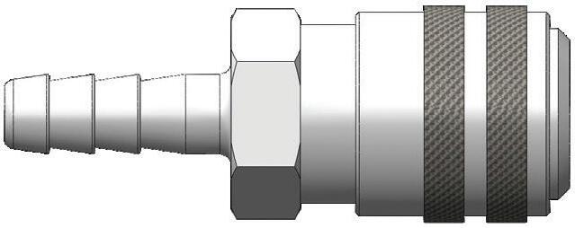
Body Size
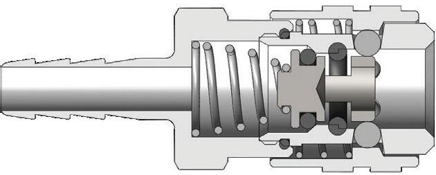
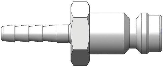
BR-Series 21-Series Interchange Coupler (Hose Barb)
Body Size
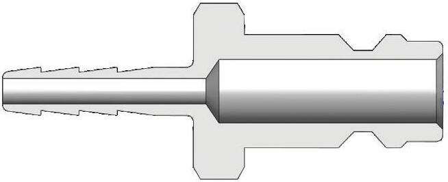
BR-Series 21-Series Interchange Plug (Hose Barb)
Pneumatic Couplings: A-Series
Interchange
Data
• Dixon Quick Coupling proprietary astronautics compact series
Materials
• Machined components are manufactured using solid steel or brass bar stock
• Stainless steel balls, retaining rings, and springs maximize corrosion resistance and extend service life
• Steel componentry is plated using RoHS-compliant trivalent chrome
• Couplers are constructed of brass with steel valve as standard
Seal Components
• Nitrile seals are standard, providing a temperature range of -40°F to 250°F (-40°C to 121°C)
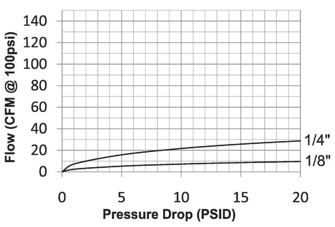
Rated Pressure Chart
Body Size
A-Series Compact (Connected) Brass Coupler/Steel Plug Brass Coupler/Plug
Technical Specifications
Body
Available Options
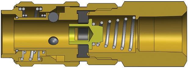
Body Size
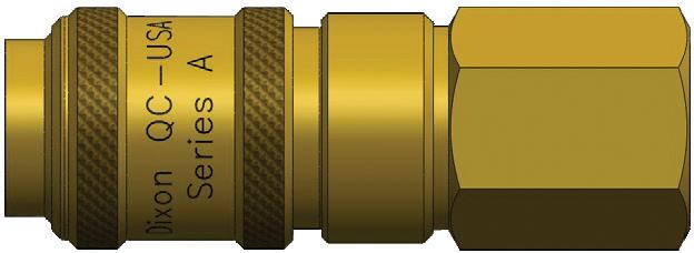
A-Series Compact Coupler (Female Threads)
Pneumatic Couplings: A-Series
Body Size
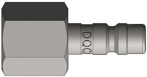
A-Series Compact Plug (Female Threads)
Body Size
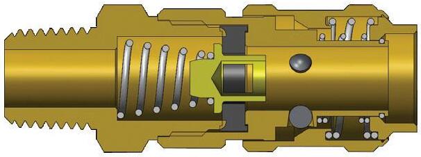
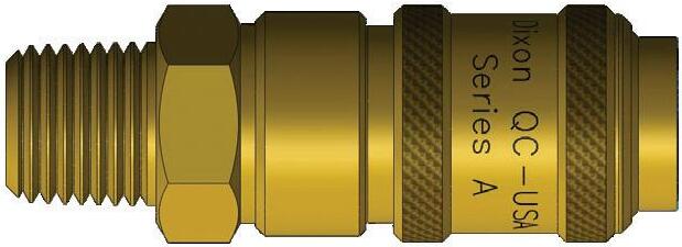
Compact Coupler (Male Threads)
Body Size
Body Size
A-Series
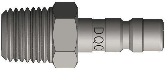
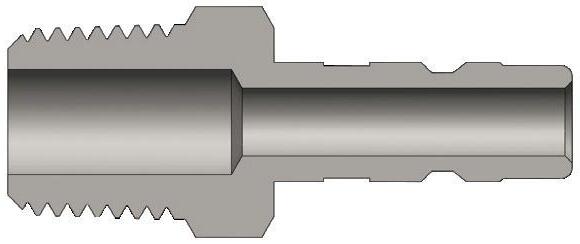
A-Series Compact Plug (Male Threads)
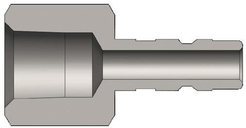
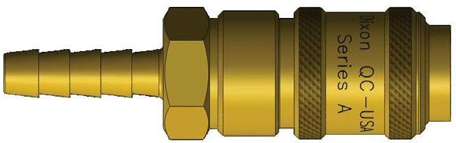
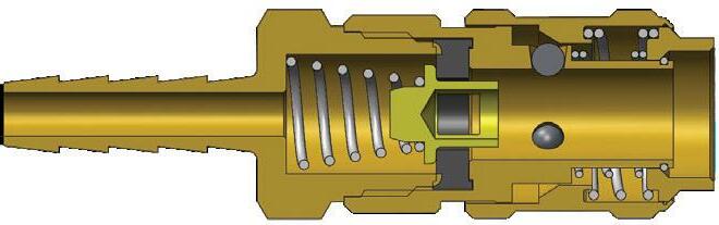
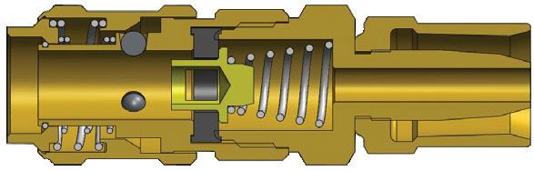
A-Series Compact Coupler (Hose Barb)
Pneumatic Couplings: A-Series
Body Size
Body Size
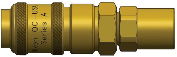
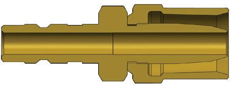
Body Size
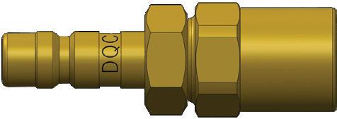
A Series Profiles
Operating pressure for couplings utilizing hose barb end connections may be dramatically reduced to that of the hose rating and/or hose end connection combination. Consult hose manufacturer's catalog for hose end connection ratings. If in doubt, test under controlled conditions for suitability to application. Dixon Quick Coupling cannot assume liability for misapplication of production resulting in equipment down-time, lost production, and/or personal injury including death.
A-Series Compact Plug (Reusable Barb)
A-Series Compact Coupler (Reusable Barb)
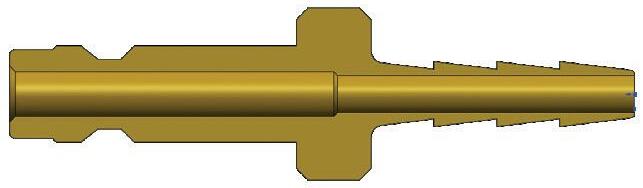
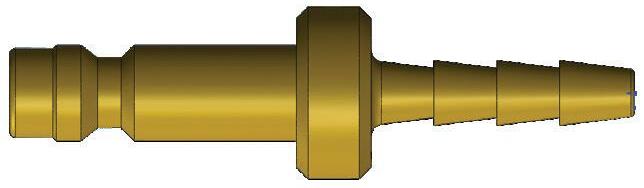
A-Series Compact Plug (Hose Barb)
Pneumatic Couplings: SCV-Series
Interchange Data
• Hansen FS-Series
Materials
• Machined components are manufactured using solid brass bar stock
• Stainless steel springs and roll-pins maximize corrosion resistance and extend service life
Seal Components
• Nitrile seals are standard, providing a temperature range of -40°F to 250°F (-40°C to 121°C)
Features
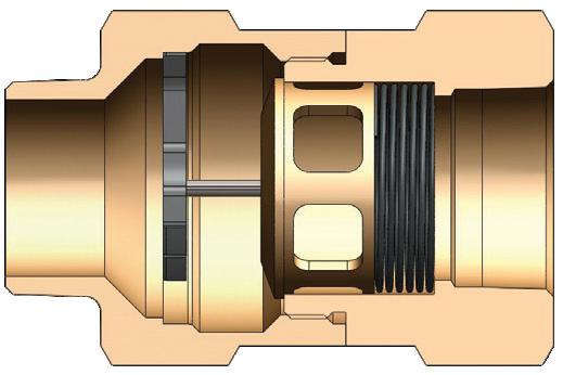
• Does not prevent backflow
• High flow design results in maximum flow with minimal pressure drop
• Automatically and instantly protects the operator against hose whip in the event of a damaged hose or coupling
• In the event of a hose rupture or coupling failure, the valve will automatically reset after the problem is fixed
• SCV-Series is available in a large selection of sizes ranging from 1/4" to 3", NPTF (BSPP/BSPT threads on request)
• Valve operation is fully compliant with OSHA Safety Regulation 1926.302(b)(7), as shown on page 14
Not recommended for applications requiring 100% of the available air supply. These applications include, but are not limited to, sand blast equipment, pile driving rigs, and expansion joint blow down pipes. It is recommended to install auxiliary safety devices, including safety cables, to ensure optimum safety for the operator in the event of a coupling failure or hose rupture.
Use
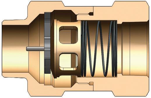
• Safety check valves operate by using the pressure differential across the valve to operate the valve and spring assembly. The pressure differential is directly related to the flow of air (SCFM) through the valve.
• When the pressure differential is within the operating limits - below the cutoff flow - of the unit, the force on the valve exerted by the spring is greater than that caused by the pressure differential (see "open position" graphic on next page). The valve remains open and normal operation continues.
• When the pressure differential is above the cutoff limit, the force on the valve exerted by the pressure differential is greater than the force exerted by the spring, and the valve closes (see "closed position" graphic on next page).
• After the repair is made, normal operation is automatically enabled when pressure across the valve equalizes through the bleeder hole.
• The valve spring size can be specified by determining the air flow during normal operation and by estimating the air flow if a failure or rupture occurs.
Technical Specifications
1Air flow rating is based upon calculated values using unobstructed air flow for the applicable hose size.
Pneumatic Couplings: SCV-Series
1Contact Dixon for cutoff flow values at other inlet pressures. *Designed for 350 PSI 1550 SCFM compressors
Hydraulic Couplings: H-Series
Interchange Data
• Interchangeable to ISO7241 Series B
• Parker 60-Series, Snap-Tite 72-Series, Hansen HK-Series, Faster Series 'HNV' Eaton/Aeroquip FD45, Stucchi Series IRB/IRBO/IRBX
Materials
• Machined components are manufactured using solid steel, brass, 303 stainless steel, or 316 stainless steel bar stock
• Stainless steel balls, retaining rings, and springs maximize corrosion resistance and extend service life
• Steel componentry is plated using RoHS-compliant trivalent chrome
• Steel coupler sleeves are hardened to resist deformation and maximize service life
• Steel plugs are hardened to provide heavy-duty performance and resist brinelling
Seal Components
• Nitrile seals are standard, providing a temperature range of -40°F to 250°F (-40°C to 121°C)
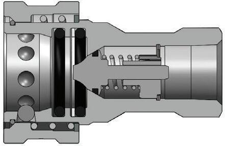
• 1/8" to 1" couplers have a redundant O-ring sealing system with PTFE backup ring. 1-1/4" to 2-1/2" have a Hytrel backup ring
• 1/4" to 1" valve seals are crimped in place to maintain integrity during excessive flow conditions and pressurized connection
Rated Pressure Chart
H-Series ISO-B Interchange (Connected)
Body Size
Technical Specifications
Hydraulic Couplings: H-Series
Body Size
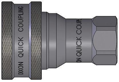
H-Series ISO-B Interchange Coupler (Female Threads)
Hydraulic Couplings: H-Series
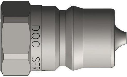
Body Size
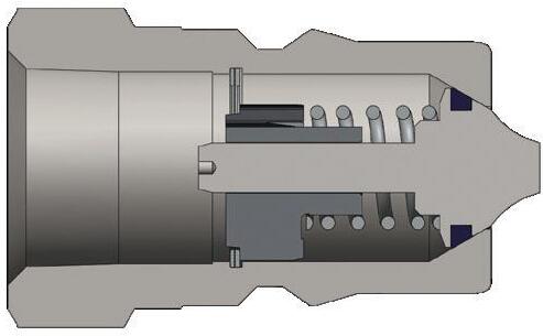
H-Series ISO-B Interchange Plug (Female Threads)
Hydraulic Couplings: H-Series
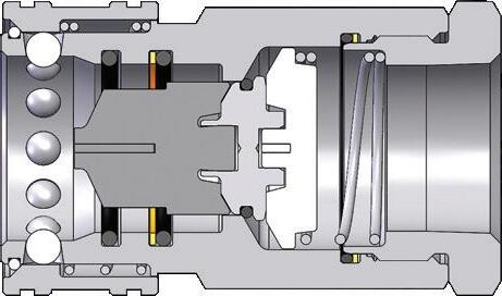
Body Size
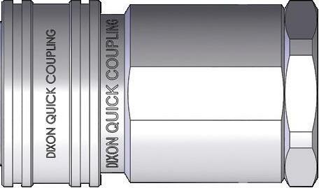
H-Series ISO-B High Volume Interchange Coupler (Female Threads)
Hydraulic Couplings: H-Series
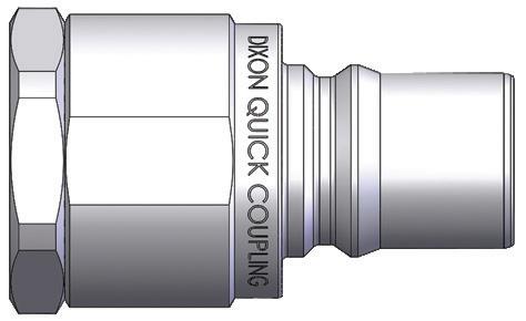
Body Size
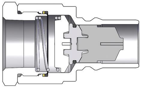
H-Series ISO-B High Volume Interchange Plug (Female Threads)
Body Size
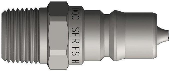
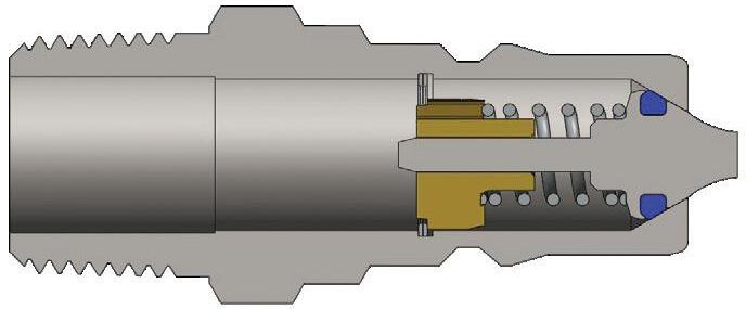
H-Series ISO-B Interchange Plug (Male Threads)
Hydraulic Couplings: H-Series
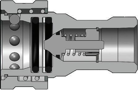
Body Size
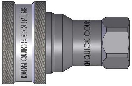
H-Series ISO-B Steel Mill 'Slide Gate' Coupler (Female Threads)
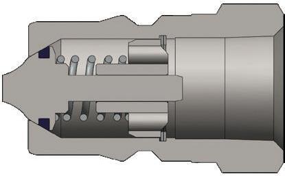
Body Size
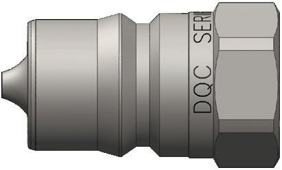
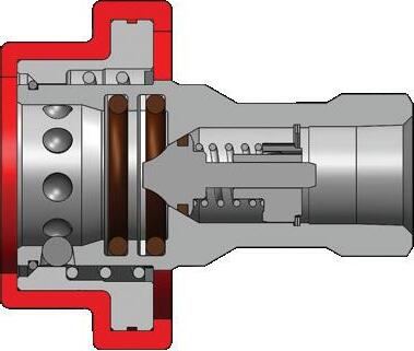
H-Series ISO-B Steel Mill 'Slide Gate' Plug (Female Threads)
Body Size
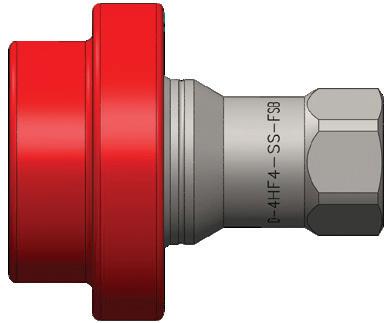
H-Series ISO-B Fry Oil Silicone Flanged Coupler (Female Threads)
Body Size
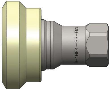
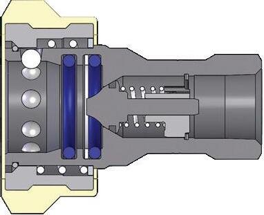
H-Series ISO-B Fry Oil Nylon Flanged Coupler (Female Threads)
Hydraulic Couplings: H-Series
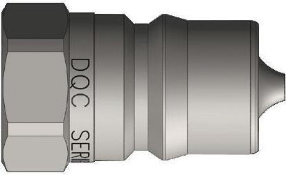
Body Size
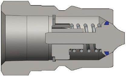
H-Series ISO-B Fry Oil Plug (Female Threads)
Available Options Body
Body
1 brass valve actuator
Body Size A B
1/8" 0.43 0.32 1/4" 0.56 0.39
3/8" 0.48 0.50
1-1/4"
H Series Profiles
Hydraulic Couplings: H-Series
Body Size
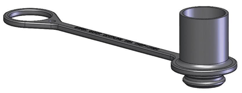
H-Series ISO-B Interchange Dust Caps and Plugs Part Detail
Coupler Dust Plug Plug Dust Cap Material
1/8" 1HDP H1DC
1/4" 2HDP-H2DC combo plug/cap
3/8" 3HDP-H3DC combo plug/cap
1/2" 4HDP-H4DC combo plug/cap
3/4" 6HDP-H6DC combo plug/cap
Nitrile
Nitrile
Nitrile
Nitrile
Nitrile 1" 8HDP-H8DC combo plug/cap1
18HDP-H8DC fits both 1" and 1-1/4" body sizes
Body Size
Nitrile
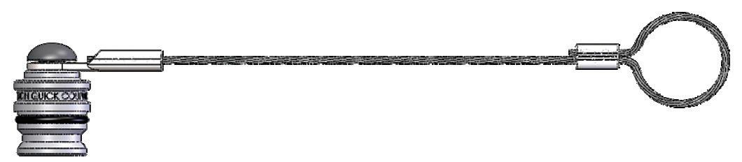
H-Series ISO-B Interchange Coupler Rigid Dust Plug Part Detail
1/4" 2HDP-A steel cable
3/8" 3HDP-A steel cable
1/2" 4HDP-A steel
1-1/2" 12HDP-A steel cable
2-1/2" 20HDP-A steel cable
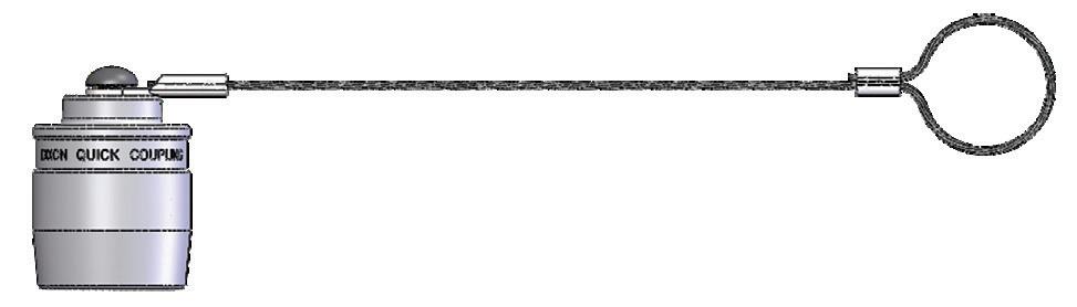
Body Size
H-Series ISO-B Interchange Plug Rigid Dust Cap Part Detail
Hydraulic Couplings: H-Series
Body Size
1/8"
1/4"
3/8"
1/2"
3/4"
1"
1-1/4"
1-1/2"
ISO-B Coupler Seal Kits Part Detail
1H-SKIT steel, 303 SS, 316 SS, brass Nitrile two O-rings and one PTFE anti-extrusion ring
F-1H-SKIT steel, 303 SS, 316 SS, brass FKM two O-rings and one PTFE anti-extrusion ring
P-1H-SKIT steel, 303 SS, 316 SS, brass EPDM two O-rings and one PTFE anti-extrusion ring
2H-SKIT steel, 303 SS, 316 SS, brass Nitrile two O-rings and one PTFE anti-extrusion ring
F-2H-SKIT steel, 303 SS, 316 SS, brass FKM two O-rings and one PTFE anti-extrusion ring
P-2H-SKIT steel, 303 SS, 316 SS, brass EPDM two O-rings and one PTFE anti-extrusion ring
3H-SKIT steel, 303 SS, 316 SS, brass Nitrile two O-rings and one PTFE anti-extrusion ring
F-3H-SKIT steel, 303 SS, 316 SS, brass FKM two O-rings and one PTFE anti-extrusion ring
P-3H-SKIT steel, 303 SS, 316 SS, brass EPDM two O-rings and one PTFE anti-extrusion ring
4H-SKIT steel, 303 SS, 316 SS, brass Nitrile two O-rings and one PTFE anti-extrusion ring
F-4H-SKIT steel, 303 SS, 316 SS, brass FKM two O-rings and one PTFE anti-extrusion ring
P-4H-SKIT steel, 303 SS, 316 SS, brass EPDM two O-rings and one PTFE anti-extrusion ring
6H-SKIT steel, 303 SS, 316 SS, brass Nitrile two O-rings and one PTFE anti-extrusion ring
F-6H-SKIT steel, 303 SS, 316 SS, brass FKM two O-rings and one PTFE anti-extrusion ring
P-6H-SKIT steel, 303 SS, 316 SS, brass EPDM two O-rings and one PTFE anti-extrusion ring
8H-SKIT steel, 303 SS, 316 SS, brass Nitrile two O-rings and one PTFE anti-extrusion ring
F-8H-SKIT steel, 303 SS, 316 SS, brass FKM two O-rings and one PTFE anti-extrusion ring
P-8H-SKIT steel, 303 SS, 316 SS, brass EPDM two O-rings and one PTFE anti-extrusion ring
10H-SKIT steel, 303 SS, 316 SS, brass Nitrile adapter/valve O-ring and two body O-rings
F-10H-SKIT steel, 303 SS, 316 SS, brass FKM adapter/valve O-ring and two body O-rings
P-10H-SKIT steel, 303 SS, 316 SS, brass EPDM adapter/valve O-ring and two body O-rings
12H-SKIT steel, 303 SS, 316 SS, brass Nitrile adapter/valve O-ring and two body O-rings
F-12H-SKIT steel, 303 SS, 316 SS, brass FKM adapter/valve O-ring and two body O-rings
P-12H-SKIT steel, 303 SS, 316 SS, brass EPDM adapter/valve O-ring and two body O-rings
H-Series
Hydraulic Couplings: H-Series
Body Size
1/4"
H-Series ISO-B Repair Kits
Part Detail Repair Kit Contents (for one coupler or plug)
2H-RKIT steel Nitrile steel valve assembly and retaining ring
2H-BRKIT brass Nitrile brass valve assembly and retaining ring
2H-SRKIT 303 stainless Nitrile 303 SS valve assembly and retaining ring
2H-SSRKIT 316 stainless
3/8"
1/2"
3/4"
1"
1-1/4"
316 SS valve assembly and retaining ring
3H-RKIT steel Nitrile steel valve assembly and retaining ring
3H-BRKIT brass Nitrile brass valve assembly and retaining ring
3H-SRKIT 303 stainless Nitrile 303 SS valve assembly and retaining ring
3H-SSRKIT 316 stainless Nitrile 316 SS valve assembly and retaining ring
4H-RKIT steel Nitrile steel valve assembly and retaining ring
4H-BRKIT brass Nitrile brass valve assembly and retaining ring
4H-SRKIT
stainless
303 SS valve assembly and retaining ring
4H-SSRKIT 316 stainless Nitrile 316 SS valve assembly and retaining ring
6H-RKIT steel Nitrile steel valve assembly and retaining ring
6H-BRKIT brass Nitrile brass valve assembly and retaining ring
6H-SRKIT 303 stainless Nitrile 303 SS valve assembly and retaining ring
6H-SSRKIT 316 stainless Nitrile 316 SS valve assembly and retaining ring
8H-RKIT steel Nitrile steel valve assembly and retaining ring
8H-BRKIT brass Nitrile brass valve assembly and retaining ring
8H-SRKIT 303 stainless Nitrile 303 SS valve assembly and retaining ring
8H-SSRKIT 316 stainless Nitrile 316 SS valve assembly and retaining ring
10H-RKIT steel
10H-BRKIT brass
10H-SRKIT
10H-SSRKIT
1-1/2"
steel valve assembly and adapter O-ring
brass valve assembly and adapter O-ring
303 SS valve assembly and adapter O-ring
316 SS valve assembly and adapter O-ring
12H-RKIT steel Nitrile steel valve assembly and adapter O-ring
12H-BRKIT brass Nitrile brass valve assembly and adapter O-ring
12H-SRKIT 303 stainless Nitrile 303 SS valve assembly and adapter O-ring
12H-SSRKIT
stainless Nitrile 316 SS valve assembly and adapter O-ring
Hydraulic Couplings: H-BOP-Series
Interchange Data
• Interchangeable to ISO7241 Series B
• Eaton/Hansen HKFR-Series, DNP HNV-BOP-Series
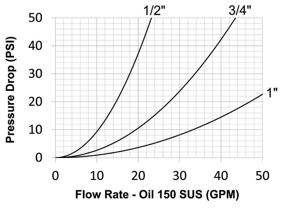
Seal Components
• Blow-out preventer (BOP) couplings contain severe service FKM seals
• PTFE anti-extrusion ring protects main coupling body seal from dynamic impulse pressure damage
• Coupler has redundant O-ring sealing system
• Valve seals are crimped in place to maintain integrity during excessive flow conditions and pressurized connection
Materials
• Machined components are manufactured using solid steel or 316 stainless steel bar stock
• Stainless steel balls, retaining rings, and springs maximize corrosion resistance and extend service life
• Steel componentry is plated using RoHS-compliant zinc-nickel
• Steel coupler sleeves are hardened to resist deformation and maximize service life
• Steel plugs are hardened to provide heavy-duty performance and resist brinelling
• Red powder coated coupler sleeve and plug hex for easy BOP service identification
• Locking sleeve is standard
• BOP couplings have been fire tested and Lloyd's certified to 1300°F (700°C) in accordance with API 16D. Certificate available upon request.
• Use H-Series dust caps and dust plugs found on page 77
Rated Pressure Chart
H-BOP-Series Blowout Preventer Safety Interchange
Body Size
Hydraulic Couplings: H-BOP-Series
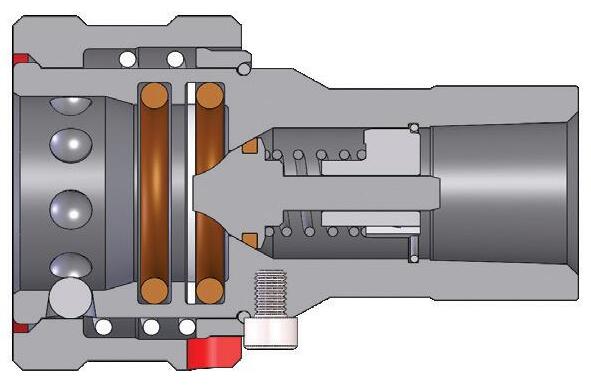
Body Size
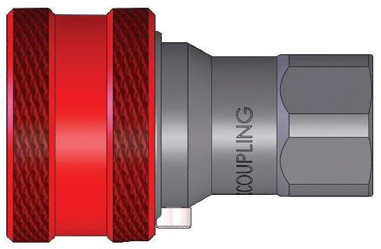
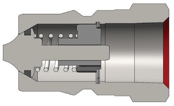
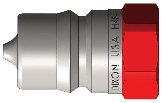
H-BOP-Series Blowout Preventer Safety Coupler (Female Threads)
Hydraulic Couplings: HS-Series
Interchange Data
• Interchangeable to ISO7241 Series B
• Parker 60-Series steam couplings
Materials
• Machined components are manufactured using solid steel, brass, or 303 stainless steel bar stock
• Stainless steel balls, retaining rings, and springs maximize corrosion resistance and extend service life
• Steel componentry is plated using RoHS-compliant trivalent chrome
• Steel plugs are hardened to provide heavy-duty performance and resist brinelling
• All couplers have a steel steam-sleeve as standard
Seal Components
• EPDM steam-grade seals are standard, providing a temperature range of -70°F to 400°F (-57°C to 204°C)
• Couplers have a redundant O-ring sealing system (dual O-rings with PTFE back-up)
• Valve seals are crimped in place to maintain integrity during excessive flow conditions
Body Size
HS-Series ISO-B Steam Interchange (Connected) Brass Coupler/Plug Brass Coupler/Steel Plug Brass Coupler/303
Technical Specifications
Maximum working pressure has been calculated using saturated steam at 382°F (194°C) for general purpose continuous steam service. For advanced operating pressure or super-heated steam applications, contact Dixon Quick Coupling for further information.
Hydraulic Couplings: HS-Series
Body Size
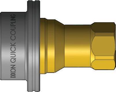
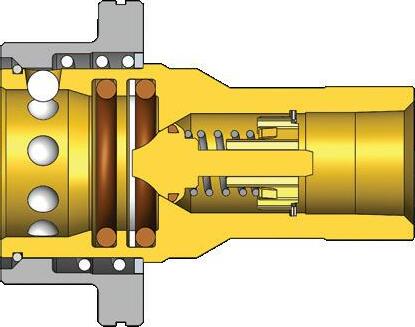
H-Series ISO-B Steam Interchange Coupler (Female Threads)
Do not disconnect steam couplings while under pressure. Maximum operating temperature for steam service couplings is 382°F (194°C), with an intermittent maximum temperature of 400°F (204°C). Be sure to use safety chains, or equivalent means, to prevent the line from thrashing around in a case where the coupling becomes disconnected.
Hydraulic Couplings: HS-Series
Body Size
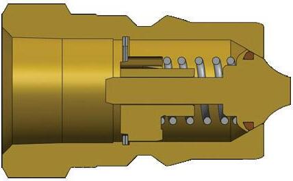
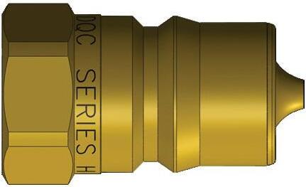
H-Series ISO-B Steam Interchange Plug (Female Threads)
Hydraulic Couplings: K-Series
Interchange Data
• Interchangeable to ISO7241 Series A
• Parker 6600-Series and Eaton/Aeroquip FD56 (5600)
• Faster ANV and Safeway S56-Series
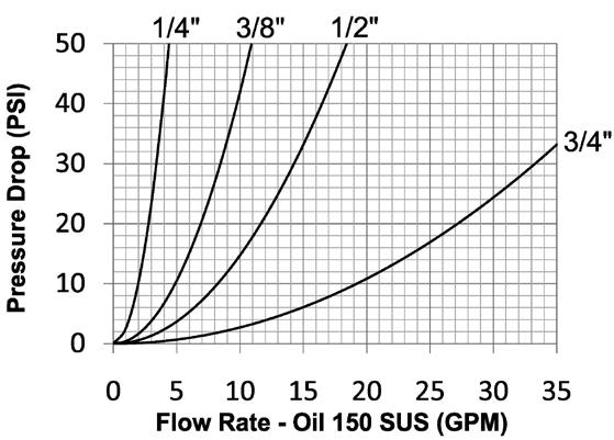
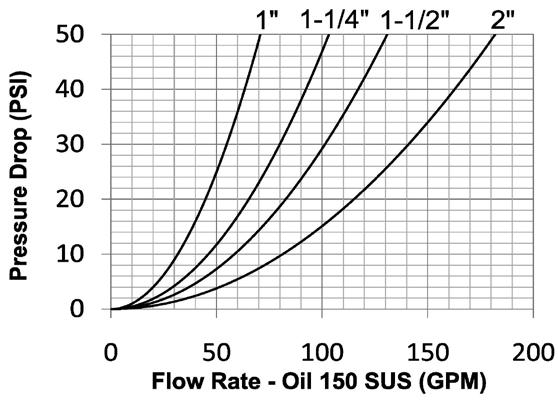
Body
Materials
• Machined components are manufactured using solid steel bar stock or 316 stainless steel bar stock
• Stainless steel balls, retaining rings, and springs maximize corrosion resistance and extend service life
• Steel componentry is plated using RoHS-compliant trivalent chrome
• Steel coupler sleeves are hardened to resist deformation and maximize service life
• Steel plugs are hardened to provide heavy-duty performance and resist brinelling
Seal Components
• Nitrile seals are standard, providing a temperature range of -40°F to 250°F (-40°C to 121°C)
• Couplers have a PTFE anti-extrusion ring
• Valve seals are crimped in place to maintain integrity during excessive flow conditions and pressurized connection
Rated Pressure Chart
K-Series ISO-A Interchange (Connected) Steel Coupler/Plug
Technical Specifications
Hydraulic Couplings: K-Series
Available Options
1Brass valve actuator
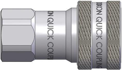
Body Size
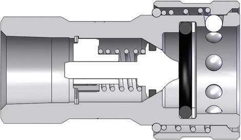
K-Series ISO-A Interchange Coupler (Female Threads)
Hydraulic Couplings: K-Series
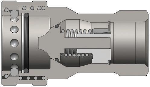
Body Size
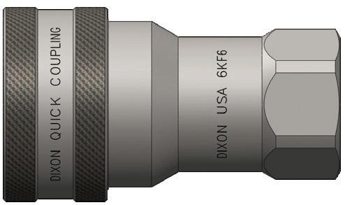
K-Series ISO-A Interchange Coupler (Female Threads)
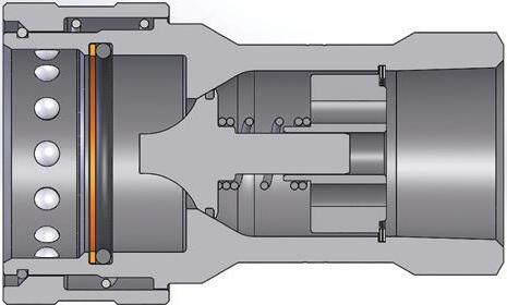
Body Size
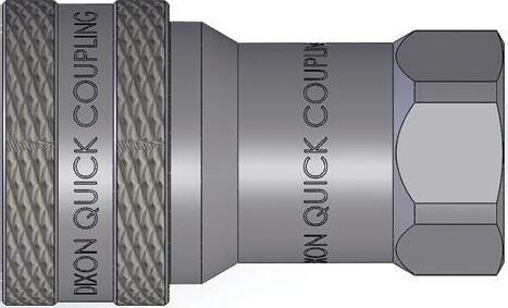
K-Series ISO-A Interchange Coupler (Female Threads)
K Profiles
Hydraulic Couplings: K-Series
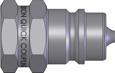
Body Size
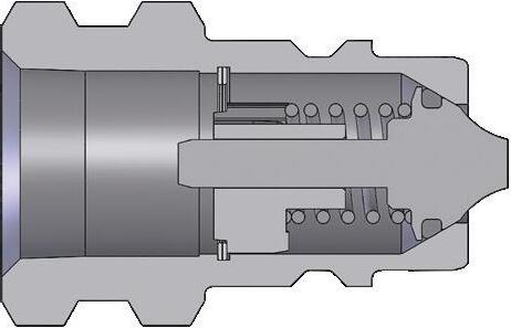
K-Series ISO-A Interchange Plug (Female Threads)
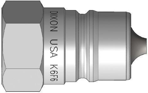
Body Size
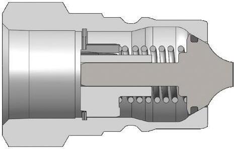
K-Series ISO-A Interchange Plug (Female Threads)
Hydraulic Couplings: K-Series
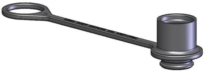
Body Size
K-Series ISO-A Interchange Combination Dust Cap and Plug Part Detail
Combination dust plug and cap
1/4" 2KDP-K2DC
Material
Nitrile
3/8" 3KDP-K3DC Nitrile
1/2" see below
3/4" 6KDP-K6DC
Nitrile 1" 8KDP-K8DC
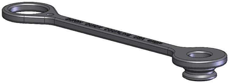
Body Size
1/2"
Body Size
1/2"
Nitrile
K-Series ISO-A Interchange Color-Coded Dust Plug Part Detail
Part # Color Material
4KDP black Nitrile
4K-R-DP red Nitrile
4K-O-DP orange Nitrile
4K-Y-DP yellow Nitrile
4K-G-DP green Nitrile
4K-B-DP blue Nitrile
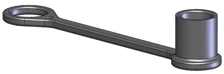
K-Series ISO-A Interchange Color-Coded Dust Cap Part Detail
Part # Color Material
K4DC black Nitrile
K4-R-DC red Nitrile
K4-O-DC orange Nitrile
K4-Y-DC yellow Nitrile
K4-G-DC green Nitrile
K4-B-DC blue Nitrile
Hydraulic Couplings: K-Series
Body Size
Body Size
Part # Lanyard
1-1/4" 10KDP-A steel cable
K-Series ISO-A-Series Dust Plug
Part Detail
Body
aluminum
1-1/2" 12KDP-A steel cable aluminum
2" 16KDP-A steel cable aluminum

Body Size
Part # Lanyard
K-Series ISO-A-Series Dust Cap Part Detail
Body
1-1/4" K10DC-A steel cable aluminum
1-1/2" K12DC-A steel cable aluminum
2" K16DC-A steel cable aluminum
K-Series ISO-A Coupler Seal Kits
Part Detail
Part # Coupler Style Seal Material
1/4" 2K-SKIT all Nitrile
3/8" 3K-SKIT all Nitrile
1/2" 4K-SKIT all Nitrile
3/4" 6K-SKIT all Nitrile
1" 8K-SKIT all Nitrile
1-1/4" 10K-SKIT all Nitrile
1-1/2" 12K-SKIT all Nitrile
2" 16K-SKIT all Nitrile
Seal Kit Contents
O-ring and PTFE anti-extrusion ring
O-ring and PTFE anti-extrusion ring
O-ring and PTFE anti-extrusion ring
O-ring and PTFE anti-extrusion ring
O-ring and PTFE anti-extrusion ring
O-ring and PTFE anti-extrusion ring
O-ring and PTFE anti-extrusion ring
O-ring and PTFE anti-extrusion ring
Hydraulic Couplings: AG-Series
Interchange Data
• Agricultural Interchange
• Parker/Pioneer 4000 Series and Faster NS/NV-Series
• Safeway Series-S20 and Stucchi IR-Series
Materials
• Machined components are manufactured using solid steel bar stock
• Stainless steel balls, retaining rings, and springs maximize corrosion resistance and extend service life
• Steel componentry is plated using RoHS-compliant trivalent chrome
• Steel coupler sleeves are hardened to resist deformation and maximize service life
• Steel plugs are hardened to provide heavy-duty performance and resist brinelling
Seal Components
• Nitrile seals are standard, providing a temperature range of -40°F to 250°F (-40°C to 121°C)
• Couplers have a PTFE anti-extrusion ring
• Poppet valve seals are crimped in place to maintain integrity during excessive flow conditions and pressurized connection
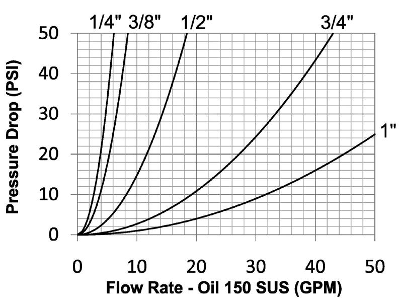
Rated Pressure Chart
Technical Specifications
Hydraulic Couplings: AG-Series
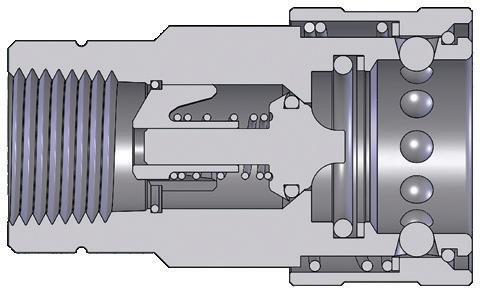
Hydraulic Couplings: AG-Series
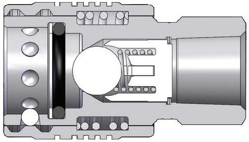
Body Size
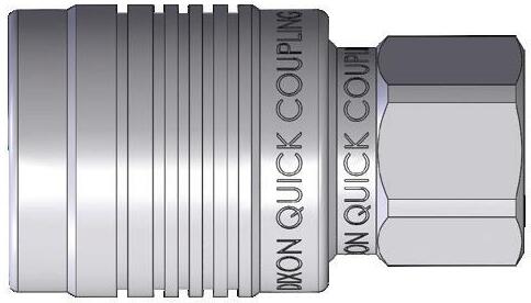
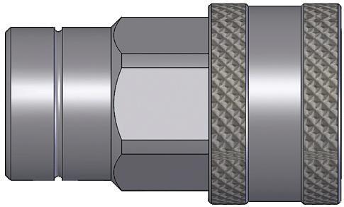
AG-Series Agricultural Interchange Push-Pull Ball Valve Coupler (Female Threads)
- 14
- 14
- 14
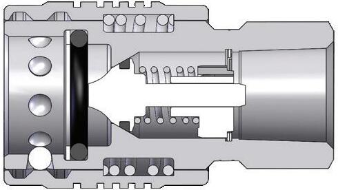
Body Size
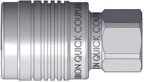
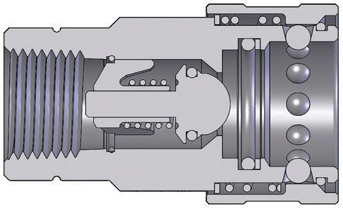
AG-Series Agricultural Interchange Push-Pull Poppet Valve Coupler (Female Threads)
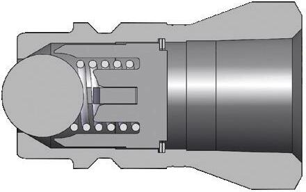
Body Size
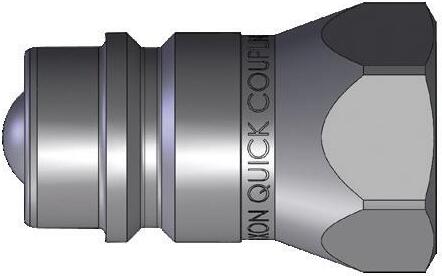
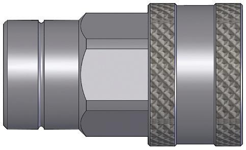
AG-Series Agricultural Interchange Ball Valve Plug (Female Threads)
Hydraulic Couplings: AG-Series
Body Size
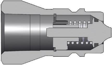
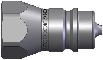
AG-Series Agricultural Interchange Poppet Valve Plug (Female Threads)
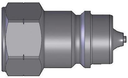
Body Size
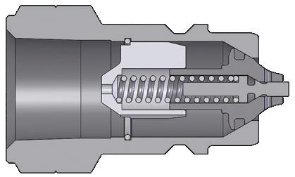
AG-Series Agricultural Interchange Connect Under Residual Pressure Plug (Female Threads)
Body Size
AG-Series Agricultural Interchange Coupler Dust Plug
Part Detail
Part # Lanyard Body
1/4" 2AGDP elastomer elastomer
3/8" 3AGDP elastomer elastomer
1/2" For 1/2" please refer to the color-coded K-Series dust caps on pg. 91
3/4" 6AGDP elastomer elastomer 1" 8AGDP elastomer elastomer

AG-Series Agricultural Interchange Plug Dust Cap
Body Size
1/2" For 1/2" please refer to the color-coded K-Series dust caps on pg. 91
3/4" AG6DC elastomer elastomer 1" AG8DC elastomer elastomer
Hydraulic Couplings: AG-Series
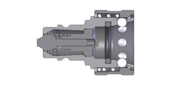
Body Size
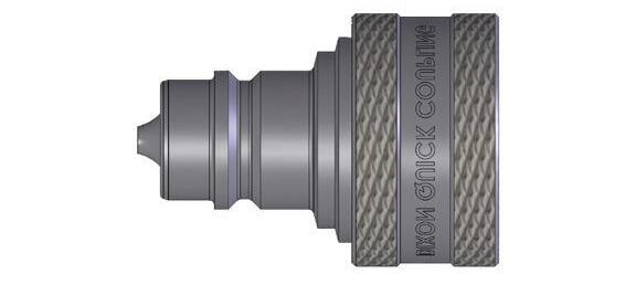
John Deere Coupler x AG-Series Agricultural Interchange Poppet Valve Plug Adapter
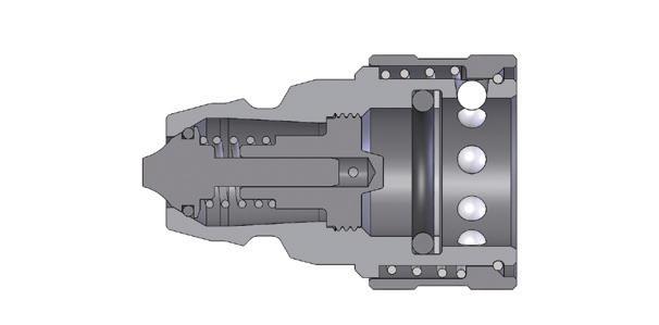
Body Size
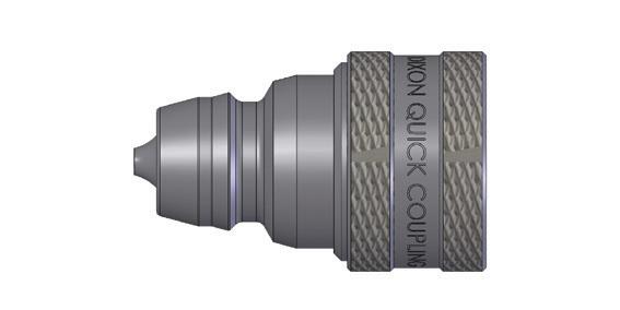
AG-Series Agricultural Interchange Poppet Coupler X John Deere Plug Adapter
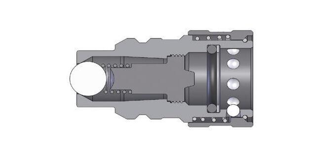
Body Size
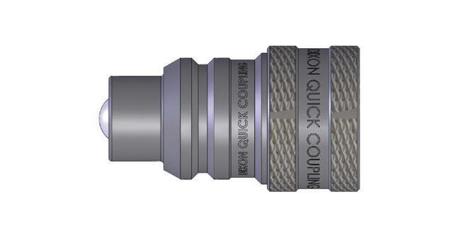
AG-Series Agricultural Interchange Ball Valve Coupler X International Harvester Plug Adapter
Body
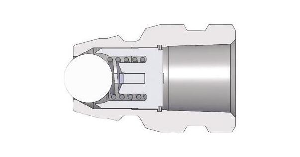
John Deere Interchange Plug X Female Threads
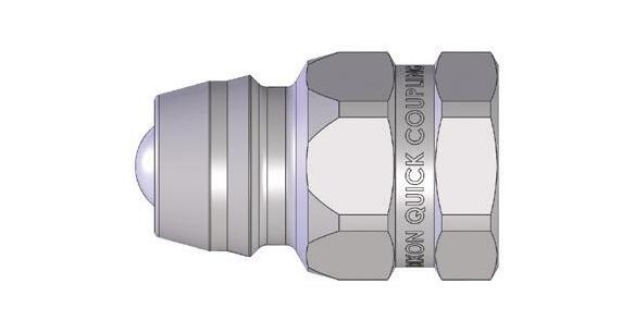
Body Size
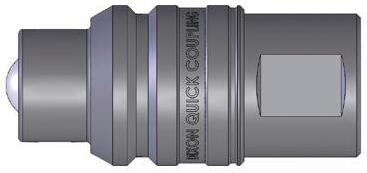
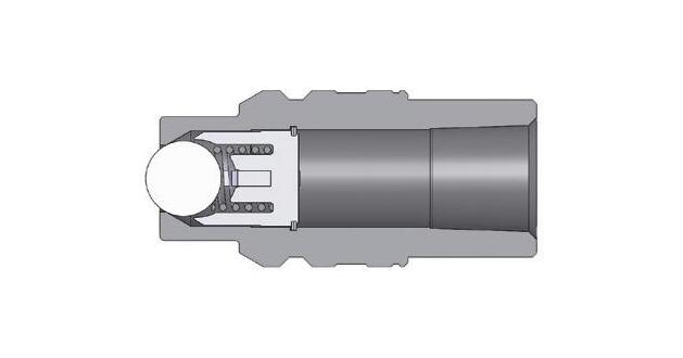
International Harvester Interchange Plug X Female Threads
Hydraulic Couplings: V-Series
Interchange Data
• Interchangeable to MIL-C-51234
• Parker/Snap-Tite H/IH and Faster TNV/TNL
Materials
• Machined components are manufactured using solid steel, brass, or 316 stainless steel bar stock
• Stainless steel balls, retaining rings, and springs maximize corrosion resistance and extend service life
• Steel componentry is plated using RoHS-compliant trivalent chrome
• Steel coupler sleeves are hardened to resist deformation and maximize service life
• Steel plugs are machined from high-strength steel and induction hardened
• Tubular TV valves are constructed from steel bar stock and are designed for optimum performance in pneumatic applications
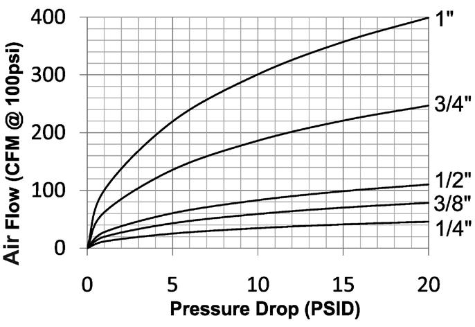
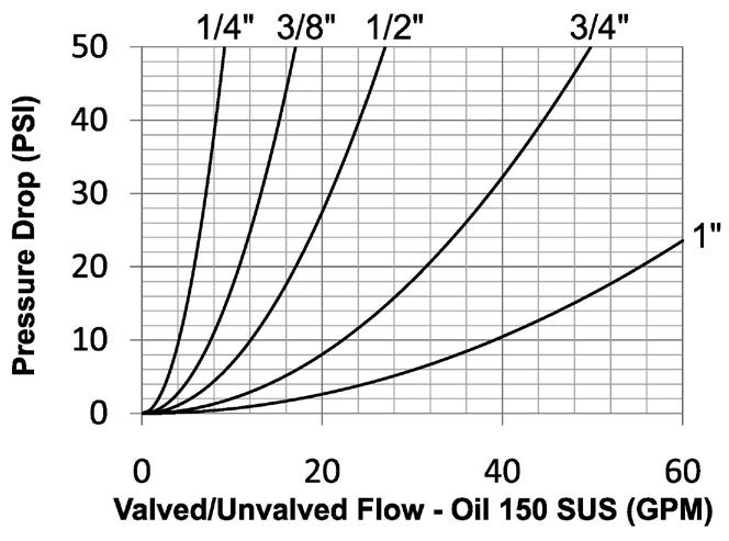
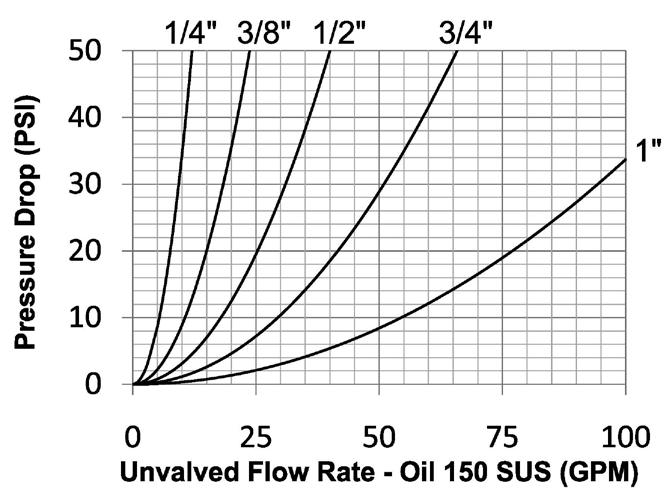
Seal Components
• Nitrile seals are standard, providing a temperature range of -40°F to 250°F (-40°C to 121°C)
• All couplers incorporate a PTFE anti-extrusion ring to protect the seal components from dynamic impulse damage
• 1/4" to 1" valve seals are crimped in place to maintain integrity during excessive flow conditions and pressurized connection
• 1-1/4" to 2" valve O-rings are retained by a unique seal-groove profile and are field replaceable
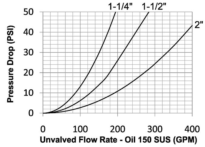
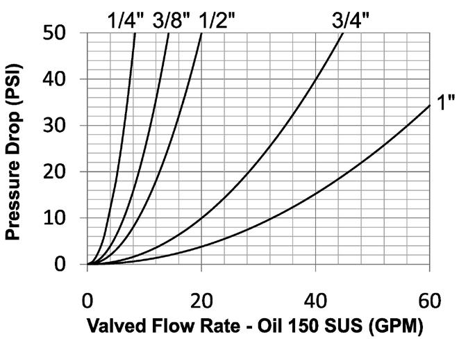
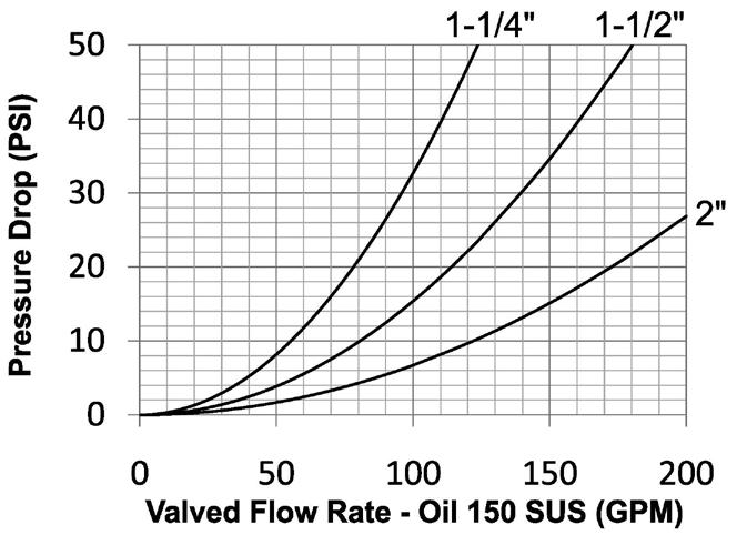
NOTE: Air flow data is presented using a coupler with a TV valve and unvalved plug. This configuration provides the optimal performance for pneumatic applications.
V-Series Profiles
Hydraulic Couplings: V-Series
Rated Pressure Chart
V-Series MIL-C-51234 (Valved
Connected)
V-Series MIL-C-51234 (Unvalved Connected) Steel Coupler/Plug
Coupler/Plug
Coupler/Plug
Technical Specifications
Hydraulic Couplings: V-Series
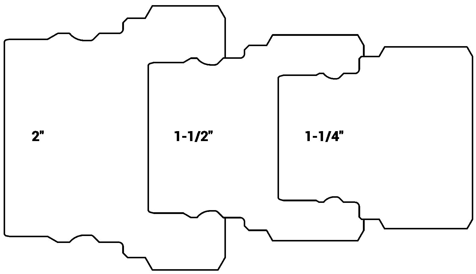
Large V-Series Profiles
Hydraulic Couplings: V-Series
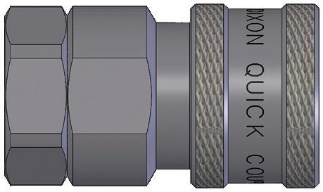
Body Size
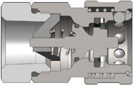
V-Series MIL-C-51234 Valved Coupler (Female Threads)
Hydraulic Couplings: V-Series
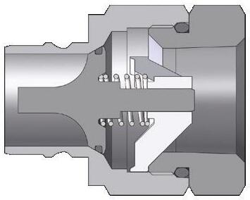
Body Size
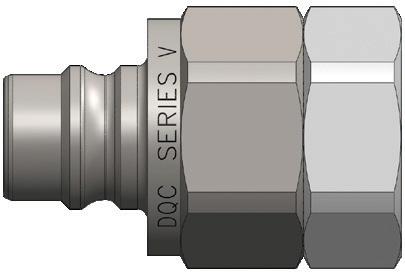
V-Series MIL-C-51234 Valved Plug (Female Threads)
Hydraulic Couplings: V-Series
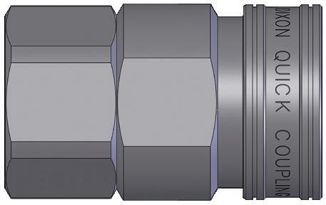
Body Size
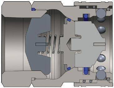
V-Series MIL-C-51234 Valved Coupler (Female Threads)
Hydraulic Couplings: V-Series
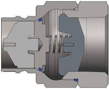
Body Size
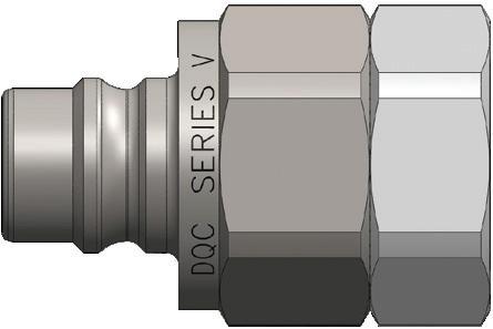
V-Series MIL-C-51234 Valved Plug (Female Threads)
Hydraulic Couplings: V-Series
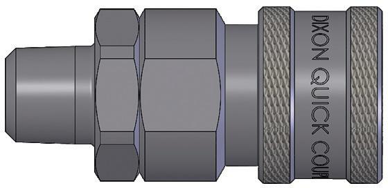
Body Size
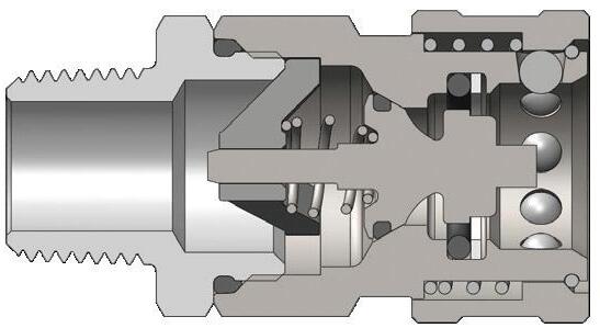
V-Series MIL-C-51234 Valved Coupler (Male Threads)
Hydraulic Couplings: V-Series
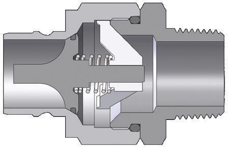
Body Size
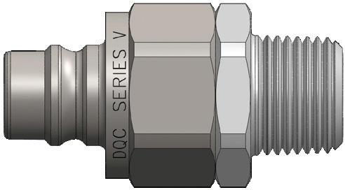
V-Series MIL-C-51234 Valved Plug (Male Threads)
Hydraulic Couplings: V-Series
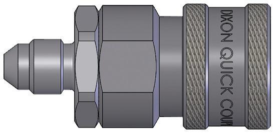
Body Size
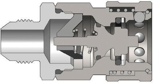
V-Series MIL-C-51234 Valved Coupler (JIC Male Threads)
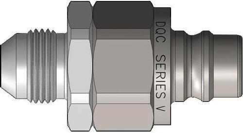
Body Size
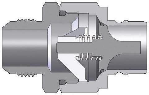
V-Series MIL-C-51234 Valved Plug (JIC Male Threads)
Hydraulic Couplings: V-Series
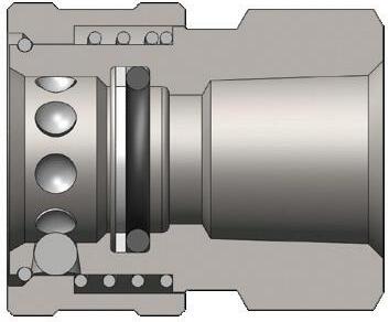
Body Size
1/4"
3/8"
1/2"
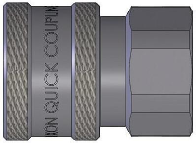
V-Series MIL-C-51234 Unvalved Coupler (Female Threads)
2VF2-E 1/4" - 18 NPTF
1/4" - 18 NPTF
1/4" - 18 NPTF
1/4" - 19 BSPP
2VBF2-B-E 1/4" - 19 BSPP brass
2VBF2-SS-E 1/4" - 19 BSPP
3/8" - 18 NPTF steel
3/8" - 18 NPTF 316
3/8" - 19 BSPP
3/8" - 19
-
1/2" - 14 NPTF
1/2" - 14 BSPP steel
3/4" - 14
Hydraulic Couplings: V-Series
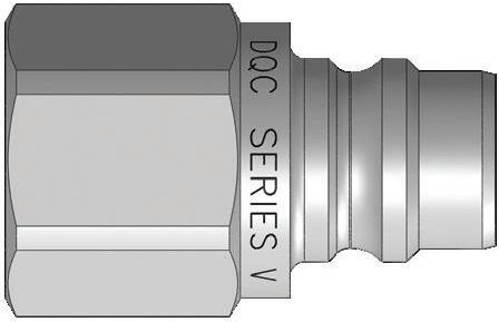
Body Size
1/2"
3/4"
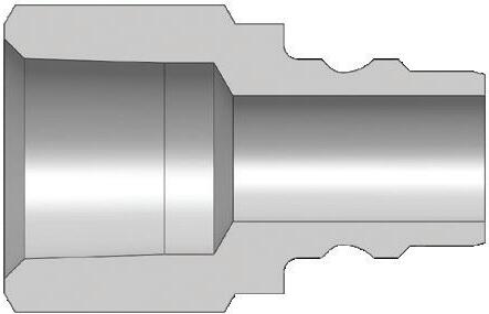
V-Series MIL-C-51234 Unvalved Plug (Female Threads)
Hydraulic Couplings: V-Series
Body Size
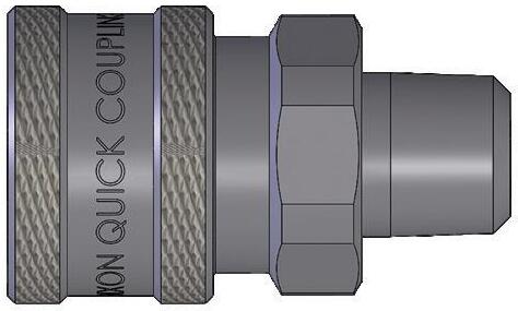
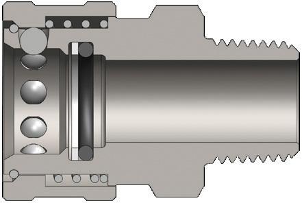
V-Series MIL-C-51234 Unvalved Coupler (Male Threads)
- 18 NPTF
Hydraulic Couplings: V-Series
Body Size
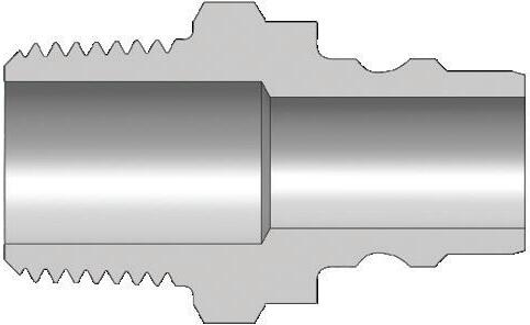
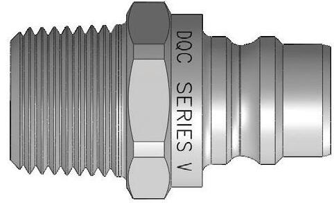
V-Series MIL-C-51234 Unvalved Plug (Male Threads)
Body Size
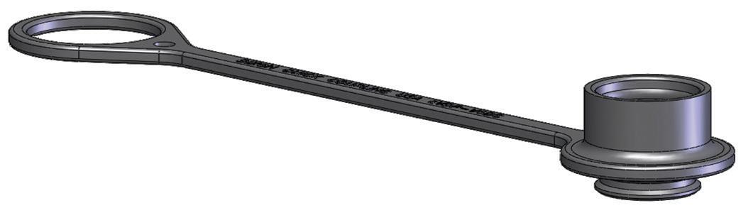
V-Series Dust Caps and Dust Plugs Part Detail
Coupler Dust Plug Plug Dust Cap Material 1/4" 1HDP V2DC
3/8" 3VDP-V3DC combination dust cap/plug
1/2" 3KDP-K3DC combination dust cap/plug
3/4" 6VDP-V6DC combination dust cap/plug
1" 8VDP-V8DC combination dust cap/plug
Hydraulic Couplings: V-Series
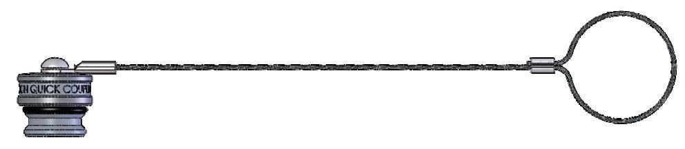
V-Series Coupler Rigid Dust Plug
Body Size
1/4" 2VDP-A
3/8" 3VDP-A
1/2" 4VDP-A
3/4" 6VDP-A
1" 8VDP-A
1-1/4" 10VDP-A
1-1/2" 12VDP-A
2" 16VDP-A
Body Size
Part Detail
cable aluminum
cable aluminum
cable aluminum
cable aluminum
cable aluminum
cable aluminum
cable aluminum
cable aluminum
1/4" V2DC-A
3/8" V3DC-A
1/2" V4DC-A
3/4" V6DC-A
1" V8DC-A
1-1/4" V10DC-A
1-1/2" V12DC-A
2" V16DC-A
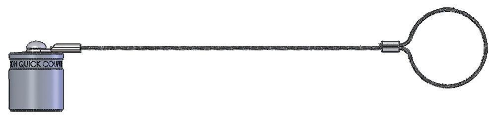
V-Series Plug Rigid Dust Cap
Part Detail
cable aluminum
cable aluminum
cable aluminum
cable aluminum
Hydraulic Couplings: V-Series
Body Size
1/4"
3/8"
1/2"
3/4"
2V-SKIT all Nitrile Body/adapter O-rings and PTFE back-up
F-2V-SKIT all FKM Body/adapter O-rings and PTFE back-up
P-2V-SKIT all EPDM Body/adapter O-rings and PTFE back-up
3V-SKIT all Nitrile Body/adapter O-rings and PTFE back-up
F-3V-SKIT all FKM Body/adapter O-rings and PTFE back-up
P-3V-SKIT all EPDM Body/adapter O-rings and PTFE back-up
4V-SKIT all Nitrile Body/adapter O-rings and PTFE back-up
F-4V-SKIT all FKM Body/adapter O-rings and PTFE back-up
P-4V-SKIT all EPDM Body/adapter O-rings and PTFE back-up
6V-SKIT all Nitrile Body/adapter O-rings and PTFE back-up
F-6V-SKIT all FKM Body/adapter O-rings and PTFE back-up
P-6V-SKIT all EPDM Body/adapter O-rings and PTFE back-up
8V-SKIT all Nitrile Body/adapter O-rings and PTFE back-up
1"
1-1/4"
1-1/2"
2"
F-8V-SKIT all FKM Body/adapter O-rings and PTFE back-up
P-8V-SKIT all EPDM Body/adapter O-rings and PTFE back-up
10V-SKIT all Nitrile Body/adapter/valve O-rings and back-up
F-10V-SKIT all FKM Body/adapter/valve O-rings and back-up
P-10V-SKIT all EPDM Body/adapter/valve O-rings and back-up
12V-SKIT all Nitrile Body/adapter/valve O-rings and back-up
F-12V-SKIT all FKM Body/adapter/valve O-rings and back-up
P-12V-SKIT all EPDM Body/adapter/valve O-rings and back-up
16V-SKIT all Nitrile Body/adapter/valve O-rings and back-up
F-16V-SKIT all FKM Body/adapter/valve O-rings and back-up
P-16V-SKIT all EPDM Body/adapter/valve O-rings and back-up
MIL-C-51234 Coupler Seal Kits
Hydraulic Couplings: V-Series
Body Size
1/4"
3/8"
1/2"
3/4"
1"
1-1/4"
1-1/2"
2"
Body Size
1/4"
3/8"
1/2"
3/4"
1"
1-1/4"
1-1/2"
V-Series MIL-C-51234 Coupler Repair Kits
Part Detail
Part # Coupler Material
Repair Kit Contents (for one coupler)
2V-RKIT steel Nitrile steel valve assembly and adapter O-ring
2V-BRKIT brass Nitrile brass valve assembly and adapter O-ring
2V-SSRKIT 316 stainless Nitrile 316 SS valve assembly and adapter O-ring
3V-RKIT steel Nitrile steel valve assembly and adapter O-ring
3V-BRKIT brass Nitrile brass valve assembly and adapter O-ring
3V-SSRKIT 316 stainless Nitrile 316 SS valve assembly and adapter O-ring
4V-RKIT steel Nitrile steel valve assembly and adapter O-ring
4V-BRKIT brass Nitrile brass valve assembly and adapter O-ring
4V-SSRKIT 316 stainless Nitrile 316 SS valve assembly and adapter O-ring
6V-RKIT steel Nitrile steel valve assembly and adapter O-ring
6V-BRKIT brass Nitrile brass valve assembly and adapter O-ring
6V-SSRKIT 316 stainless Nitrile 316 SS valve assembly and adapter O-ring
8V-RKIT steel Nitrile steel valve assembly and adapter O-ring
8V-BRKIT brass Nitrile brass valve assembly and adapter O-ring
8V-SSRKIT 316 stainless Nitrile 316 SS valve assembly and adapter O-ring
140030-10 steel Nitrile steel valve assembly and adapter O-ring 140032-10 316 stainless Nitrile 316 SS valve assembly and adapter O-ring
140030-12 steel Nitrile steel valve assembly and adapter O-ring 140032-12 316 stainless Nitrile 316 SS valve assembly and adapter O-ring
140030-16 steel Nitrile steel valve assembly and adapter O-ring 140032-16 316 stainless Nitrile 316 SS valve assembly and adapter O-ring
V-Series MIL-C-51234 Plug Repair Kits
V2-RKIT steel Nitrile steel valve assembly and adapter O-ring
V2-BRKIT brass Nitrile brass valve assembly and adapter O-ring
V2-SSRKIT 316 stainless Nitrile 316 SS valve assembly and adapter O-ring
V3-RKIT steel Nitrile steel valve assembly and adapter O-ring
V3-BRKIT brass Nitrile brass valve assembly and adapter O-ring
V3-SSRKIT 316 stainless Nitrile 316 SS valve assembly and adapter O-ring
V4-RKIT steel Nitrile steel valve assembly and adapter O-ring
V4-BRKIT brass Nitrile brass valve assembly and adapter O-ring
V4-SSRKIT 316 stainless Nitrile 316 SS valve assembly and adapter O-ring
V6-RKIT steel Nitrile steel valve assembly and adapter O-ring
V6-BRKIT brass Nitrile brass valve assembly and adapter O-ring
V6-SSRKIT 316 stainless Nitrile 316 SS valve assembly and adapter O-ring
V8-RKIT steel Nitrile steel valve assembly and adapter O-ring
V8-BRKIT brass Nitrile brass valve assembly and adapter O-ring
V8-SSRKIT 316 stainless Nitrile 316 SS valve assembly and adapter O-ring
140030-10 steel Nitrile steel valve assembly and adapter O-ring
140032-10 316 stainless Nitrile 316 SS valve assembly and adapter O-ring
140030-12 steel Nitrile steel valve assembly and adapter O-ring
140032-12 316 stainless Nitrile 316 SS valve assembly and adapter O-ring 2"
140030-16 steel Nitrile steel valve assembly and adapter O-ring
140032-16 316 stainless Nitrile 316 SS valve assembly and adapter O-ring
Hydraulic Couplings: TR-Series
Interchange Data
• European Interchange
• TEMA 3800, 5000, 7500, 10000 Series
• CEJN Series 525 Materials
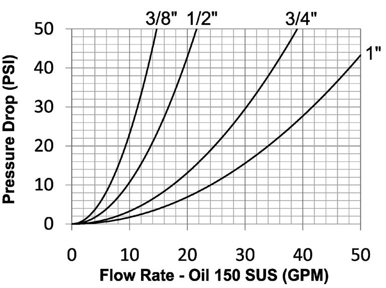
Body Size
• Machined components are manufactured using solid steel bar stock
• Stainless steel balls, retaining rings, and springs maximize corrosion resistance and extend service life.
• Steel componentry is plated using RoHS-compliant trivalent chrome
• Steel coupler sleeves are hardened to resist deformation and maximize service life
• Steel plugs are hardened to provide heavy-duty performance
Seal Components
• Nitrile seals are standard, providing a temperature range of -40°F to 250°F (-40°C to 121°C)
• Couplers have a redundant O-ring sealing system (dual O-rings with inner PTFE back-up ring)
• Valve seals are crimped in place to maintain integrity during excessive flow conditions and pressurized connection
Rated Pressure Chart
TR-Series European Interchange (Connected) Steel Coupler/Plug
Technical Specifications
Interchange Profiles
TR
Hydraulic Couplings: TR-Series
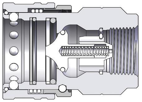
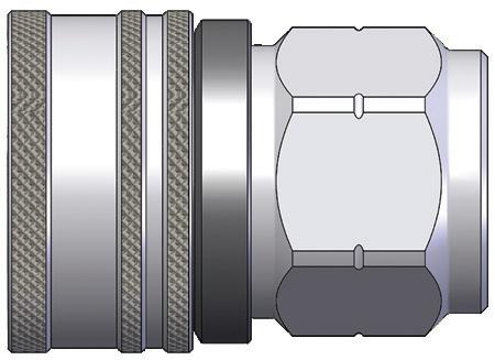
TR-Series European Interchange Coupler (Female Threads)
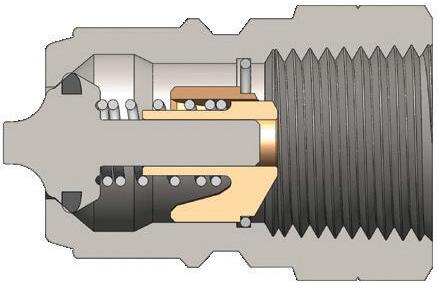
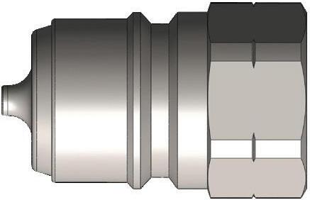
TR-Series European Coupler Seal Kits
3/8" 3TR-SKIT all Nitrile two O-rings and one PTFE back-up ring
1/2" 4TR-SKIT all Nitrile two O-rings and one PTFE back-up ring
3/4" 6TR-SKIT all Nitrile two O-rings and one PTFE back-up ring 1" 8TR-SKIT all Nitrile two O-rings and one PTFE back-up ring
Please contact Dixon for dust caps and dust plugs.
Hydraulic Couplings: MCS
Applications
Modular Connection System (MCS)

• Agricultural, automotive, demolition, die casting, mobile construction equipment, oil and gas, railroad, snow and ice removal, steel, forestry, and mining
Sizes
• 3/8”, 1/2”, 3/4”, and 1”
Features
• A single system that holds multiple hydraulic quick couplings
• Modularity: Blocks can be configured to meet customer needs (patent pending)
• Innovative coupling retention system for easy field repair (patent pending)
• Versatile: Up to 10 couplings can be used at once depending on size
• 450+ configurations possible
• 17-4 stainless steel alignment pins maximize corrosion resistance
• Cam-style latching mechanism helps provide a smooth connection
• HTE (male) and HTZ (female) coupling technology enables connections under residual pressure
• Lockout/Tagout capable
Approvals
• All working configurations approved 3000 PSI working pressure
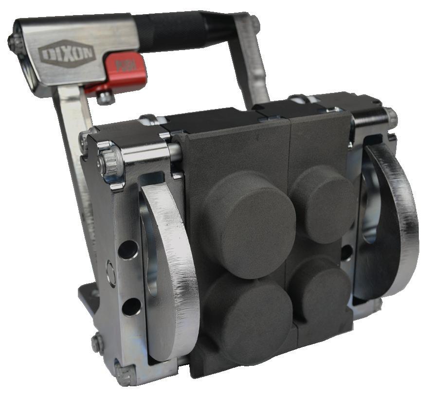
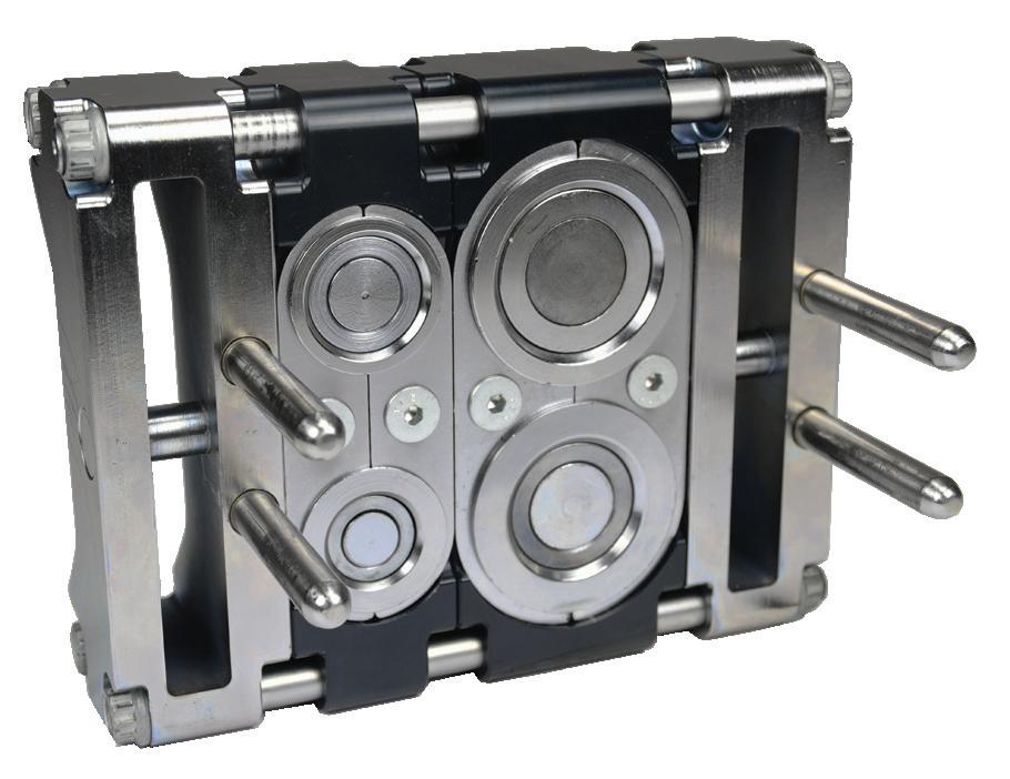
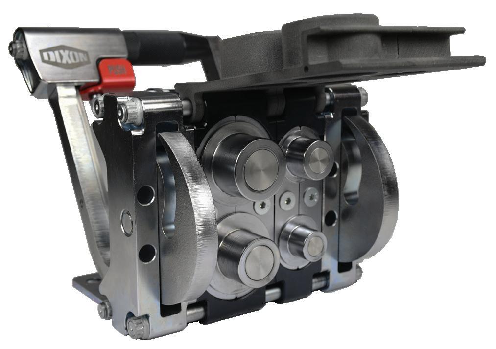
MCF11110-A000
MCM11110-A000
Hydraulic Couplings: MCS
Modular Connection System (MCS) Part Number Key
Modular Connection System Ex. MCF22010-B001 MC Half Designator
Half Designator Code
Fixed F
Mobile M
Number of 1” Fittings Code
Zero to four 0-4
Number of 3/4” Fittings Code
Zero to four 0-4
Number of 1/2” Fittings Code
Zero to nine 0-9
Ten X
Number of 3/8” Fittings Code
Zero to nine 0-9
Ten X Number of 1/4” Fittings Code
Zero to nine 0-9
Ten X
Variant Category Code
Default A
Fitting arrangement B
Custom thread ends C
Custom dust caps D
Electrical connections E
Custom seals F
Custom labeling G
Custom anodization H
Multiple variations J
Custom brackets K
Variant Number Code 000 to 999 000999
Number of 1” Fittings
Number of 3/4” Fittings
Number of 1/2” Fittings
Number of 3/8” Fittings
Number of 1/4” Fittings
Variant Category Variant Number
NOTE: The MCS utilizes nitrile rubber seals and NPTF end connections unless otherwise specified. Certain configurations may require consultation. Contact Dixon® for more information.
Hydraulic Couplings: HT-Series Correct Connect®
Interchange Data
• Interchangeable to ISO16028
• Parker FEM-Series, Holmbury HQ-Series, Hansen FF, Eaton/ Aeroquip FD89, Stucchi FIRG/Series A, Faster FFH/FFN/FFI/2FFN/2FFI, Safeway FF49-Series
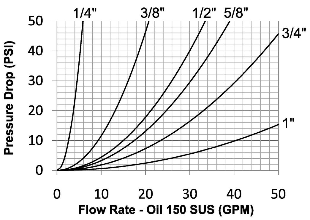
Materials
• Machined components are manufactured using solid steel or 316 stainless steel bar stock
• Stainless steel balls, retaining rings, and springs maximize corrosion resistance and extend service life
• Steel componentry is plated using RoHS compliant zinc nickel for corrosion resistance
• Steel coupler sleeves are hardened to resist deformation and maximize service life
• Steel plugs are hardened to provide resistance to brinelling during impulse service
Seal Components
• 1/4", 3/8", 1/2", 3/4", and 1" plugs have molded polyurethane valve seals, with a temperature range of -65°F to 212°F (-54°C to 100°C)
• 5/8" plugs have Nitrile-energized PTFE valve seals, with a temperature range of -40°F to 250°F (-40°C to 121°C)
• Couplers have a polyurethane valve stem O-ring, with a temperature range of -65°F to 212°F (-54°C to 100°C)
• Ancillary coupler and plug seals are Nitrile (Nitrile-N), with a temperature range of -40°F to 250°F (-40°C to 121°C)
• PTFE or TPC-ET anti-extrusion ring protects main coupling valve seal from dynamic impulse pressure damage
HT-Series Correct Connect®
• Blue bands standard, color bands sold separately
• Contact Dixon for additional color band builds
• No special tools required
• Polyurethane color bands
Rated Pressure Chart
Technical Specifications
Flush Face
Hydraulic Couplings: HT-Series Correct Connect
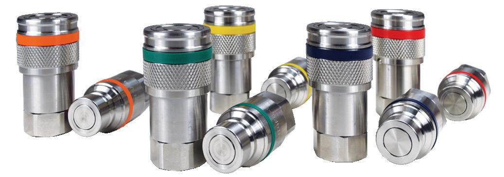
Color Bands Part # Guide
1/4" coupler band
1/4" plug band
3/8" coupler band
3/8" plug band
2HTBAND-B 2HTBAND-O 2HTBAND-G 2HTBAND-Y
HT2BAND-B
HT2BAND-O HT2BAND-G
HT2BAND-Y
2HTBAND-R
HT2BAND-R
3HTBAND-B 3HTBAND-O 3HTBAND-G 3HTBAND-Y 3HTBAND-R
HT3BAND-B
HT3BAND-O HT3BAND-G
HT3BAND-Y
HT3BAND-R
1/2" coupler band 4HTBAND-B 4HTBAND-O 4HTBAND-G 4HTBAND-Y 4HTBAND-R
1/2" plug band
HT4BAND-B HT4BAND-O HT4BAND-G HT4BAND-Y HT4BAND-R
5/8" coupler band 5HTBAND-B 5HTBAND-O 5HTBAND-G 5HTBAND-Y 5HTBAND-R
5/8" plug band
HT5BAND-B HT5BAND-O HT5BAND-G HT5BAND-Y HT5BAND-R
3/4" coupler band 6HTBAND-B 6HTBAND-O 6HTBAND-G 6HTBAND-Y 6HTBAND-R
3/4" plug band
HT6BAND-B HT6BAND-O HT6BAND-G HT6BAND-Y HT6BAND-R 1" coupler band 8HTBAND-B 8HTBAND-O 8HTBAND-G 8HTBAND-Y 8HTBAND-R 1" plug band
HT8BAND-B HT8BAND-O HT8BAND-G HT8BAND-Y HT8BAND-R
Series Profile
Hydraulic Couplings: HT-Series Correct Connect®
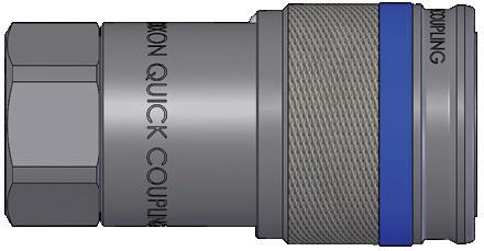
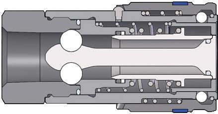
HT-Series ISO16028 Flush Face Interchange Coupler (Female Threads)
Hydraulic Couplings: HT-Series Correct Connect®
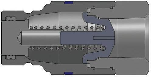
Body Size
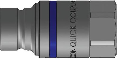
HT-Series ISO16028 Flush Face Interchange Plug (Female Threads)
- 14
Hydraulic Couplings: HT-Series Correct Connect®
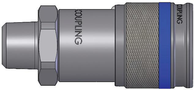
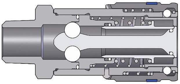
HT-Series ISO16028 Flush Face Interchange Coupler (Male Threads)
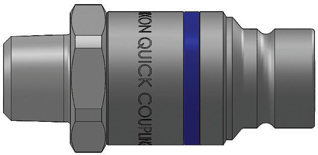
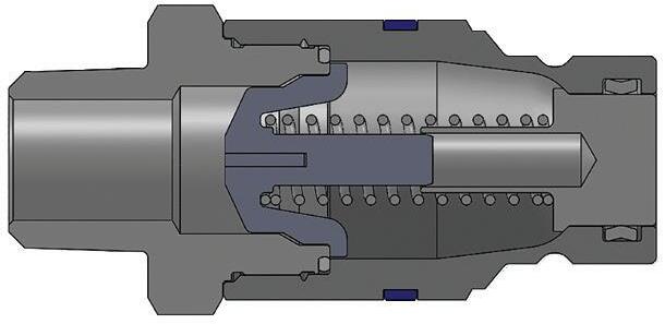
HT-Series ISO16028 Flush Face Interchange Plug (Male Threads)
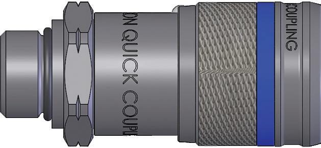
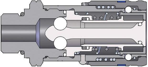
HT-Series ISO16028 Flush Face Interchange Coupler (Male ORB Threads)
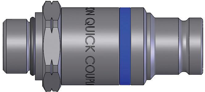
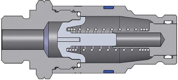
HT-Series ISO16028 Flush Face Interchange Plug (Male ORB Threads)
Hydraulic Couplings: HT-Series Correct
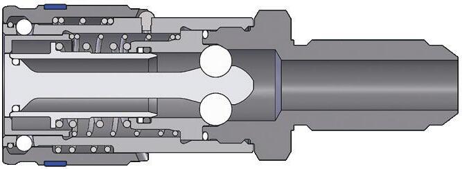
Body Size
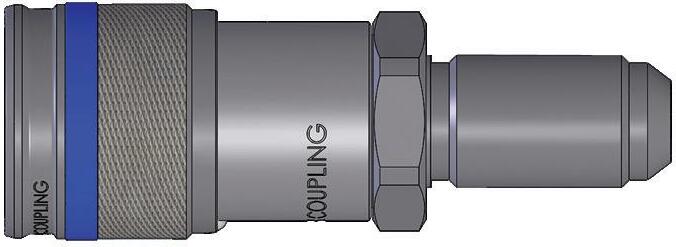
HT-Series ISO16028 Flush Face Interchange Coupler (Male Bulkhead Threads)
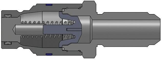
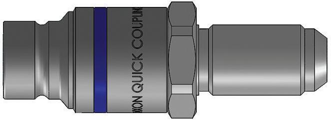
HT-Series ISO16028 Flush Face Interchange Plug (Male Bulkhead Threads)
Hydraulic Couplings: HT-Series Correct Connect®
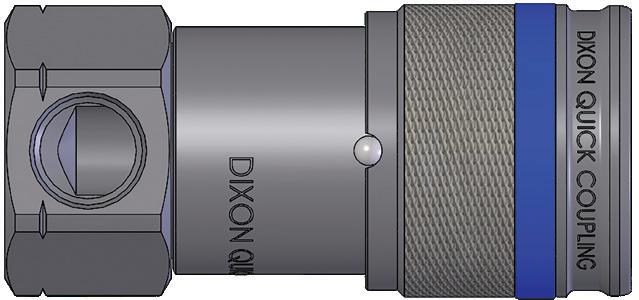
Body Size
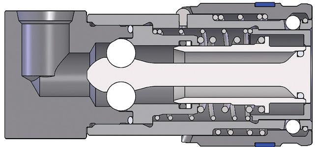
HT-Series Flush Face 90° Female Threaded Coupler
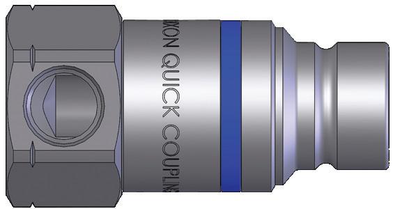
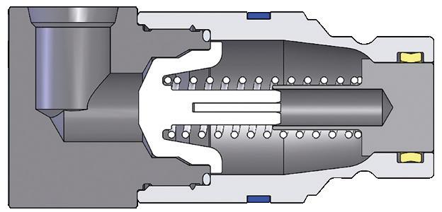
HT-Series Flush Face 90° Female Threaded Plug
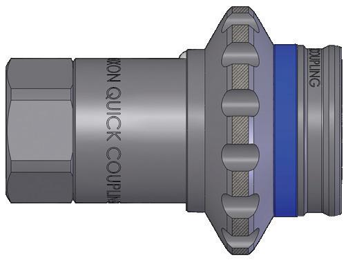
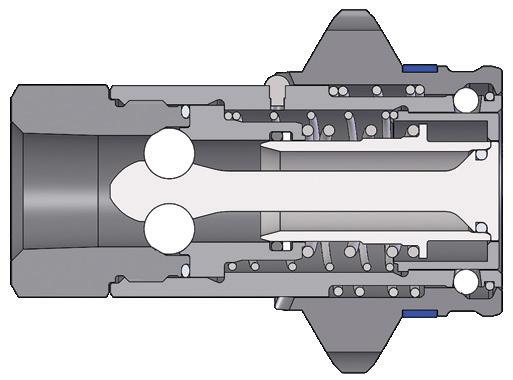
HT-Series ISO16028 Flush Face Interchange Coupler with Flange Sleeve
Hydraulic Couplings: HT-Series Correct Connect
Body Size
1/4"
3/8"
1/2"
5/8"
3/4"
Body Size
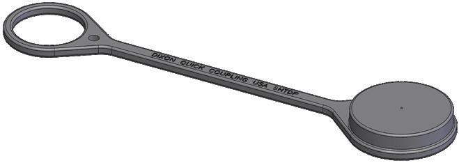
HT-Series ISO16028 Flush Face Coupler Dust Cap Part Detail
Part #
1/4" 2HTDP
Body
Nitrile
3/8" 3HTDP Nitrile
1/2" 4HTDP Nitrile
5/8" 5HTDP Nitrile
3/4" 6HTDP Nitrile
1" 8HTDP Nitrile
Body Size
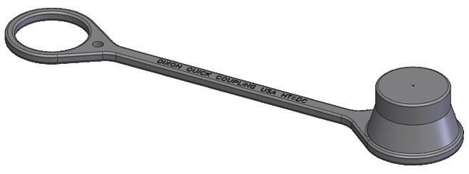
HT-Series ISO16028 Flush Face Coupler Dust Cap Part Detail
Part #
Body
1/4" HT2DC Nitrile
3/8" HT3DC Nitrile
1/2" HT4DC Nitrile
5/8" HT5DC Nitrile
3/4" HT6DC Nitrile 1" HT8DC Nitrile
HT-Series ISO16028 Flush Face Interchange Coupler Seal Kits
Part Detail
Part # Coupler Style Seal Material
2HT-SKIT all Nitrile
3HT-SKIT all Nitrile
4HT-SKIT all Nitrile
5HT-SKIT all Nitrile
6HT-SKIT all Nitrile
1" 8HT-SKIT all Nitrile
Body Size
1/4"
3/8"
1/2"
5/8"
3/4"
1"
Seal Kit Contents
stem/adapter/gland O-ring, gland B.U.
stem/adapter/gland O-ring, gland B.U.
stem/adapter/gland O-ring, gland B.U.
stem/adapter/gland O-ring, gland B.U.
stem/adapter/gland O-ring, gland B.U.
stem/adapter/gland O-ring, gland B.U.
HT-Series ISO16028 Flush Face Interchange Plug Seal Kits
Part Detail
HT2-SKIT-V2 all Nitrile main valve seal and adapter O-ring
HT3-SKIT-V2 all Nitrile
main valve seal and adapter O-ring
HT4-SKIT-V2 all Nitrile main valve seal and adapter O-ring
HT5-SKIT-V2 all
HT6-SKIT-V2 all
HT8-SKIT-V2 all
Nitrile main valve seal and adapter O-ring
Nitrile main valve seal and adapter O-ring
Nitrile main valve seal and adapter O-ring
Hydraulic Couplings: HTE-Series
Interchange Data
• Parker FEC-Series, Stucchi APM-Series, Faster 3FFH-Series
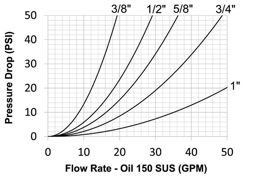
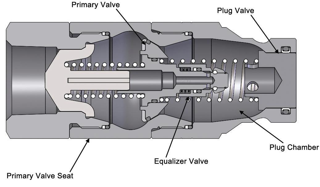
Materials
• Machined components are manufactured using solid steel bar stock
• Steel componentry is plated using a RoHS compliant zincnickel process providing corrosion resistance
• Stainless steel retaining rings and springs maximize corrosion resistance and extend service life
• Plugs are hardened to provide resistance to brinelling during impulse service
Seal Components
• 3/8", 1/2", 3/4", and 1" plugs have molded polyurethane valve seals, with a temperature range of -65°F to 212°F (-54°C to 100°C)
• 5/8" plugs have Nitrile-energized PTFE valve seals, with a temperature range of -40°F to 250°F (-40°C to 121°C)
• Ancillary plug seals are Nitrile with a temperature range of -40°F to 250°F (-40°C to 121°C)
• Backup rings for all sizes are PTFE
Component Terminology
• Non-linear connection force at many pressures
• No maximum connection-pressure restrictions
• Head pressure or valve bleed-by has minimal effect on connection force
• Less susceptible to system contamination
• Design is scalable performing similarly in many sizes
• Smooth connection action
Rated Pressure Chart
Hydraulic Couplings:
The Connection Process
Stage 1: The Disconnected State
The plug has residual pressure trapped behind the primary valve, while the coupler has no trapped pressure.
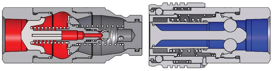
Stage 2: Plug Chamber Evacuated
The plug valve is opened, then the socket valve opens, evacuating the plug chamber to the unpressurized socket.
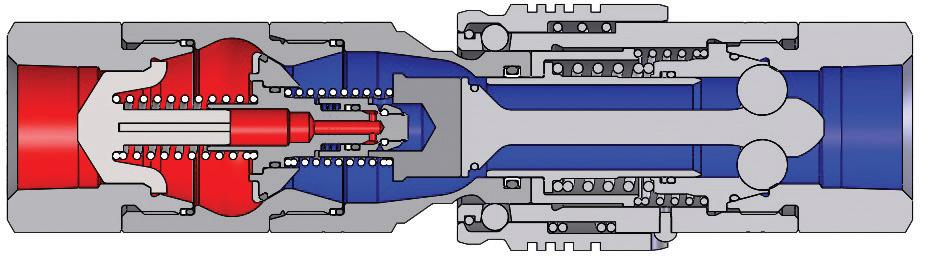
Stage 3: Release Pressure
The connection continues, with the valve being activated, releasing the trapped pressure into the plug chamber, then to the unpressurized socket.
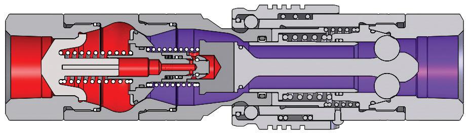
Stage 4: Complete the Connection
The primary valve can now open easily, since there is no longer any pressure trapped behind it, allowing the socket to fully engage the plug.
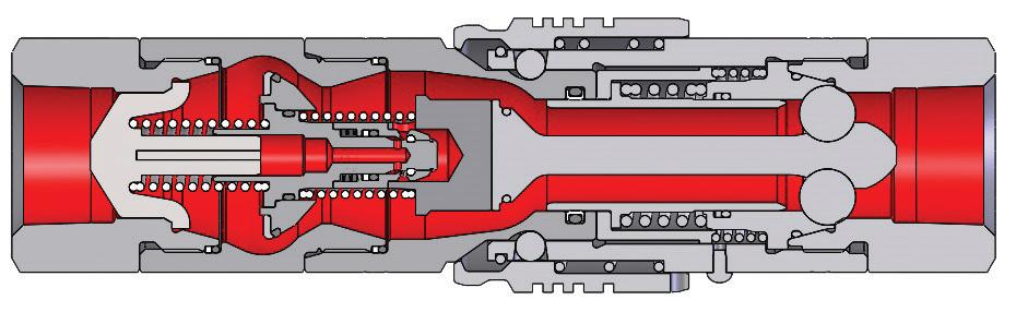
Hydraulic Couplings: HTE-Series
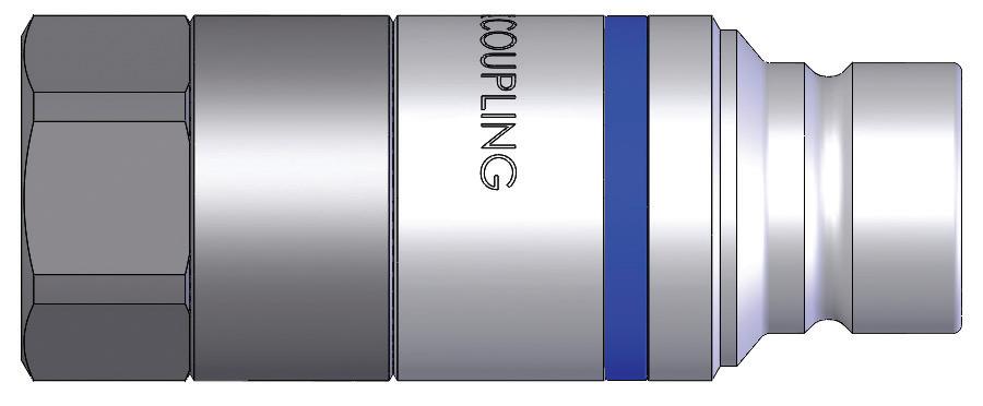
• For use with HT-Series couplers
Body Size
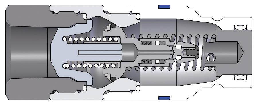
HTE-Series ISO 16028 Connect Under Pressure Flush Face Plug (Female Threads)
Hydraulic Couplings: HTZ-Series
Body Size
Interchange Data
• Interchangeable to ISO16028
Materials
• Machined components are manufactured using solid steel or 316 stainless steel bar stock
• Stainless steel balls, retaining rings, and springs maximize corrosion resistance and extend service life
• Steel componentry is plated using RoHS compliant zincnickel for corrosion resistance
• Steel coupler sleeves are hardened to resist deformation and maximize service life
• Steel plugs are hardened to provide resistance to brinelling during impulse service
Seal Components
• 1/2" plugs have molded polyurethane valve seals, with a temperature range of -65°F to 212°F (-54°C to 100°C)
• Couplers have a polyurethane valve stem O-ring, with a temperature range of -65°F to 212°F (-54°C to 100°C)
• Ancillary coupler and plug seals are Nitrile with a temperature range of -40°F to 250°F (-40°C to 121°C)
• PTFE or TPC-ET anti-extrusion ring protects main coupling valve seal from dynamic impulse pressure damage
Rated Pressure Chart
HTZ-Series ISO16028 Flush Face
Coupler/Plug Coupled 316 SS Coupler/Plug Coupled Steel Coupler Uncoupled Steel Plug Uncoupled
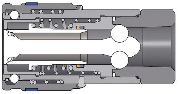
Body Size
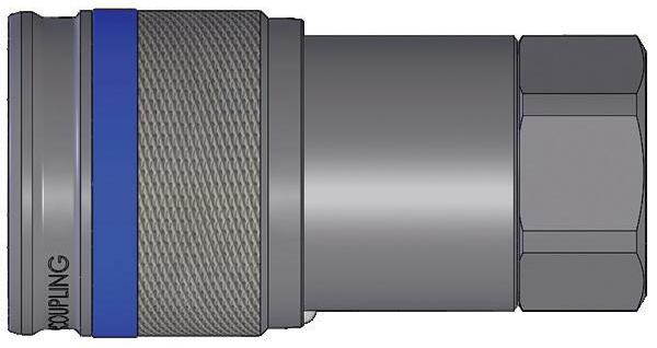
HTZ-Series ISO16028 Connect Under Pressure Flush Face Coupler
Hydraulic Couplings: HT-AG-Series
Interchange Data
• Agricultural Interchange, Parker/Pioneer 4000 Series, Faster NS/NV-Series, Safeway Series-S20, and Stucchi IRSeries
• Conforms to ISO16028 interchange standard, with Eaton/ Hansen FF, Parker FEM, Faster FFH/2FFN/2FFI, Stucchi A/ FIRG, and Holmbury HQ/A/FIMC
Materials
• Machined components are manufactured using solid bar stock
• Stainless steel balls, retaining rings, and springs maximize corrosion resistance and extend service life
• Steel componentry is plated using RoHS-compliant trivalent chrome
• Steel coupler sleeves are hardened to resist deformation and maximize service life
Seal Components
• HT-series couplers have polyurethane valve stem O-ring, with a temperature range of -65° to 212°F (-54°C to 100°C)
• Ancillary HT-series coupler seals are Nitrile with a temperature range of -40°F to 250°F (-40°C to 121°C)
• PTFE or TPC-ET anti-extrusion ring protects main coupling valve seal from dynamic impulse pressure damage
• Nitrile seals are standard in AG-series coupler and plug
• AG-series couplers have a PTFE anti-extrusion ring
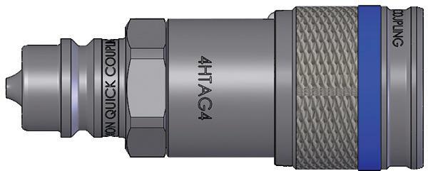
Body Size
Body
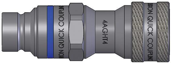
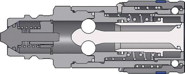
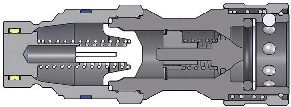
HT-AG-Series Flush Face ISO16028 Coupler x ISO7241-A AG Plug Adapter
HT-AG-Series ISO7241-A AG Coupler x ISO16028 Flush Face Plug Adapter
Chart
Hydraulic Couplings: XK-Series
Interchange Data
• 10K Flush face
• Interchanges with Parker FH-Series
Materials
• Machined components are manufactured using solid bar stock
• Stainless steel balls, retaining rings, and springs maximize corrosion resistance and extend service life
• Steel componentry is plated using RoHS-compliant zinc nickel for corrosion resistance
• Steel plugs are hardened to provide resistance to brinelling
• Plugs have molded polyurethane valve seals, with a temperature range of -65°F to 212°F (-54°C to 100°C)
• Couplers have a polyurethane valve stem O-ring, with a temperature range of -65°F to 212°F (-54°C to 100°C)
• Ancillary coupler and plug seals are Nitrile with a temperature range of -40°F to 250°F (-40°C to 121°C)
• PTFE or TPC-ET anti-extrusion ring protects main coupling valve seal from dynamic impulse pressure damage
Feature
• Automatic locking mechanism
Pressure Chart
Technical Specifications
Rated
Hydraulic Couplings: XK-Series
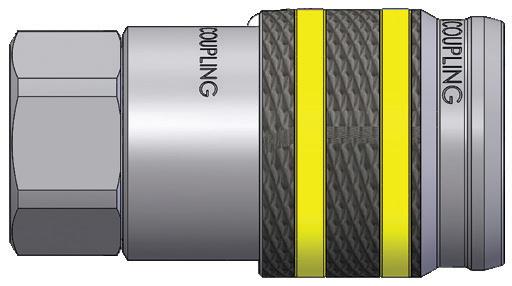
Body Size
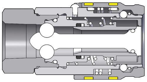
XK-Series 10K Flush Face Coupler (Female Threads)
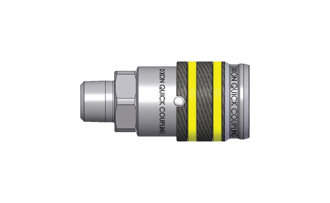
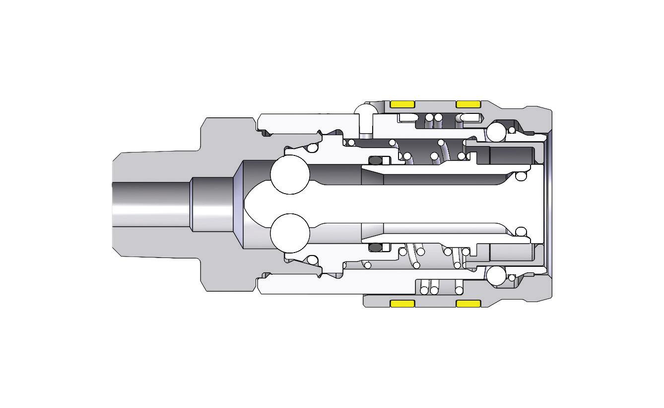
XK-Series 10K Flush Face Coupler (Male Threads)
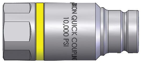
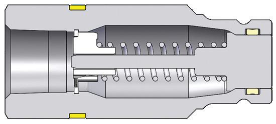
XK-Series 10K Flush Face Plug (Female Threads)
Hydraulic Couplings: ST-Series
Interchange Data
• Interchangeable with Parker/Snap-Tite 71-Series
Materials
• Machined components are manufactured using solid steel or 316 stainless bar stock
• Stainless steel balls, retaining rings, and springs maximize corrosion resistance and extend service life
• Steel componentry is plated using RoHS-compliant trivalent chrome
• Steel coupler sleeves are hardened to resist deformation and maximize service life
• Steel plugs are hardened to provide heavy-duty performance
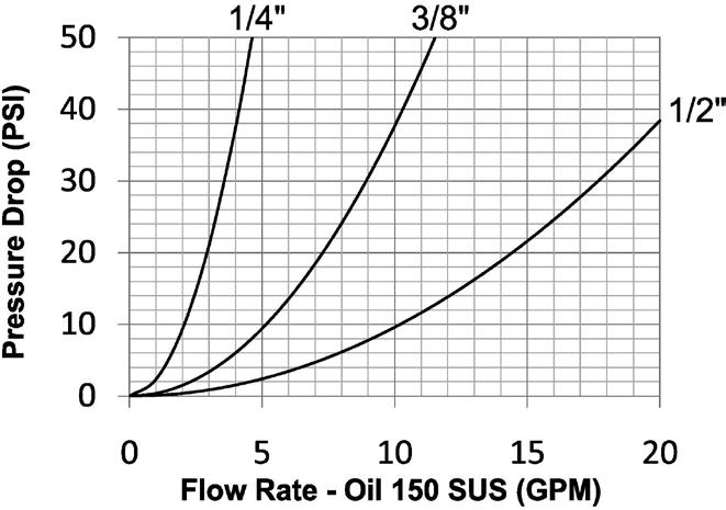
• All couplers and plugs incorporate PTFE anti-extrusion rings to protect the seal components from dynamic impulse damage Seal Components
• Nitrile seals are standard, providing a temperature range of -40°F to 250°F (-40°C to 121°C)
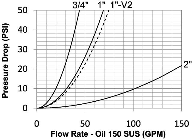
Rated Pressure Chart
ST-Series Heavy-Duty Flush Face
Body Size
Coupler/Plug Coupled
Technical Specifications
Hydraulic Couplings: ST-Series
Available Options
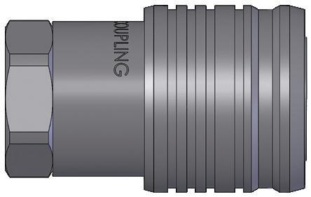
Body Size
3/8"
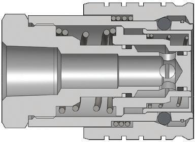
ST-Series Heavy-Duty Flush Face Coupler (Female Threads)
Hydraulic Couplings: ST-Series
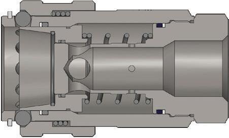
Body Size
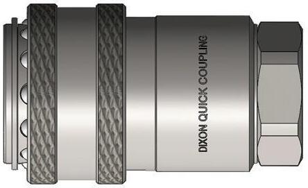
ST-Series Heavy-Duty Flush Face Coupler (Female Threads)
Body Size
ST-Series Heavy-Duty Flush Face 'Old Style' Coupler (Female Threads)
ST-Series Profiles
Body Size A B
Hydraulic Couplings: ST-Series
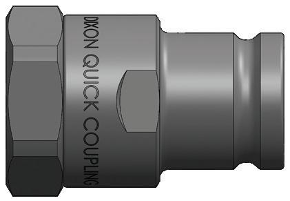
Body Size
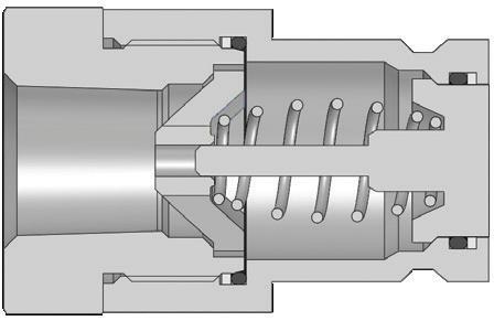
ST-Series Heavy-Duty Flush Face Plug (Female Threads)
Hydraulic Couplings: ST-Series
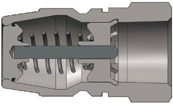
Body Size
Body Size
Body Size
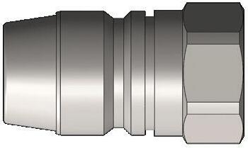
ST-Series Heavy-Duty Flush Face Plug (Female Threads)
ST-Series Heavy-Duty Flush Face 'Old Style' Plug (Female Threads)
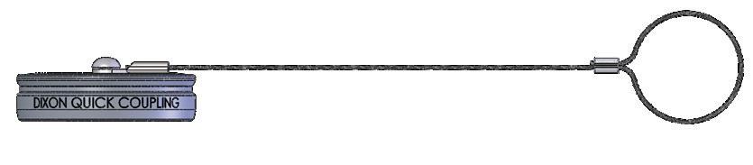
ST-Series Coupler Dust Plug Part Detail Part # Lanyard
1/4" 2STDP-A steel cable aluminum
3/8" 3STDP-A steel cable aluminum
1/2" 4STDP-A steel cable aluminum
3/4" 6STDP-A steel cable aluminum 1" 8STDP-A steel cable aluminum 1"-V2 8STDP-A-V2 steel cable aluminum 2" 16STDP-A steel cable aluminum
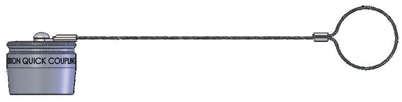
Body Size
3/4"
1"
steel cable
ST-Series Plug Dust Cap Part Detail
Hydraulic Couplings: ST-Series
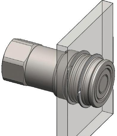
ST-Series Heavy-Duty Flush Face Coupler Bulkhead Kits
Body Size
Part Detail
Part # Mounting Hole ID Ring Material
Bulkhead Kit Contents
1/4" 2ST-BMK 1.250" steel two 360° retaining rings
3/8" 3ST-BMK 1.625" steel two 360° retaining rings
1/2" 4ST-BMK 2.000" steel two 360° retaining rings
3/4" 6ST-BMK 2.375" steel two 360° retaining rings
ST-Series Heavy-Duty Flush Face Coupler Seal Kits
Body Size
Part Detail
Part # Coupler Style Seal Material
Seal Kit Contents
1/4" 2ST-SKIT all Nitrile two seals and anti-extrusion rings
3/8" 3ST-SKIT all Nitrile two seals and anti-extrusion rings
1/2" 4ST-SKIT all Nitrile two seals and anti-extrusion rings
3/4" 6ST-SKIT all Nitrile two seals and anti-extrusion rings
1" 8ST-SKIT all Nitrile two seals and anti-extrusion rings
1" 8ST-SKIT-V2 all Nitrile three seals and two anti-extrusion rings
2" 16ST-SKIT all Nitrile three seals and two anti-extrusion rings
Body Size
Part Detail
ST-Series Heavy-Duty Flush Face Plug Seal Kits
Seal Kit Contents
Part # Coupler Style Seal Material
1/4" ST2-SKIT all Nitrile valve O-ring/back-up and adapter O-ring
3/8" ST3-SKIT all Nitrile valve O-ring/back-up and adapter O-ring
1/2" ST4-SKIT all Nitrile valve O-ring/back-up and adapter O-ring
3/4" ST6-SKIT all Nitrile valve O-ring/back-up and adapter O-ring
1" ST8-SKIT all Nitrile valve O-ring/back-up and adapter O-ring
2" ST16-SKIT all Nitrile main valve seal
Hydraulic Couplings: PD-Series
Interchange Data
• Interchangeable to ISO15171-1
• Parker PD-Series, Eaton/Aeroquip FD90
Materials
• Machined components are manufactured using solid steel bar stock
• Stainless steel springs, carbon steel balls, and retaining rings
• Steel plugs are machined from solid steel bar stock and hardened
• Steel componentry is plated using RoHS-compliant trivalent chrome
Body Size
Body Size
Seal Components
• Nitrile seals are standard, providing a temperature range of -40°F to 250°F (-40°C to 121°C)
• PTFE anti-extrusion ring protects main coupler O-ring from dynamic impulse pressure damage
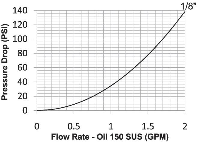
Rated Pressure Chart
PD-Series ISO15171-1 Diagnostic Interchange
Steel Coupler/Plug Connected
Working Burst
Standards
Technical Specifications
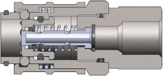
Body Size
Steel Plug Disconnected
Working Burst
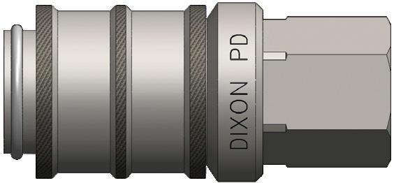
PD-Series ISO15171-1 Diagnostic Coupler (Female Threads)
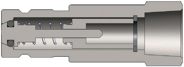
Body Size
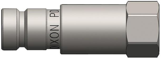
PD-Series ISO15171-1 Diagnostic Plug (Female Threads)
Hydraulic Couplings: PD-Series
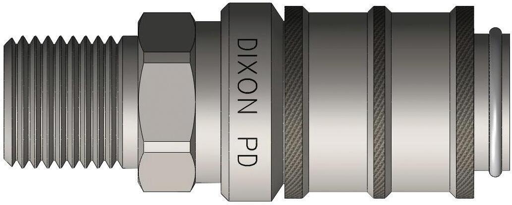
Body Size
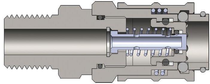
PD-Series ISO15171-1 Diagnostic Coupler (Male Threads)
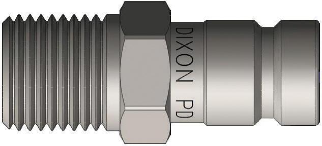
Body Size
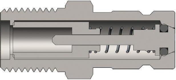
PD-Series ISO15171-1 Diagnostic Plug (Male Threads)
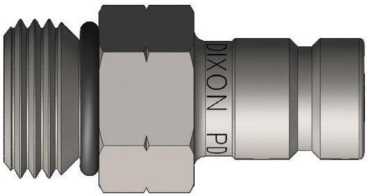
Body Size
Body Size
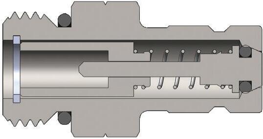
PD-Series ISO15171-1 Diagnostic Plug (Male ORB Threads)
PD-Series Plug Dust Cap Part Detail
PD-Series Profile
Hydraulic Couplings: VEP-Series
Interchange Data
• Stucchi VEP-P/VEP-HD Series, DNP PST4/FSI Series, Voswinkel FT Series, Parker FET-Series, and Holmbury HFT Series
Seal Components
• Plugs have Nitrile-energized PTFE valve seals, with a temperature range of -40°F to 250°F (-40C° to 121°C)
• 3/8" plugs have molded polyurethane valve seals, with a temperature range of -65°F to 212°F (-54°C to 100°C)
• 3/8" to 3/4" valve stems have molded acetal seals, with a temperature range of -65°F to 212°F (-54°C to 100°C)
• 1" to 2" valve stems have molded polyurethane seals, with a temperature range of -65°F to 212°F (-54°C to 100°C)
• Ancillary coupler and plug seals are Nitrile with a temperature range of -40°F to 250°F (-40C° to 121°C)
• TPC-ET anti-extrusion ring protects main coupling valve seal from dynamic impulse pressure damage
Materials
• Machined components are manufactured using solid steel bar stock
• Stainless steel retaining rings and springs maximize corrosion resistance and extend service life
• Steel componentry is plated using RoHS compliant zinc nickel for corrosion resistance
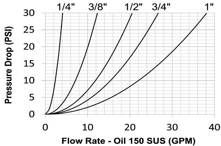
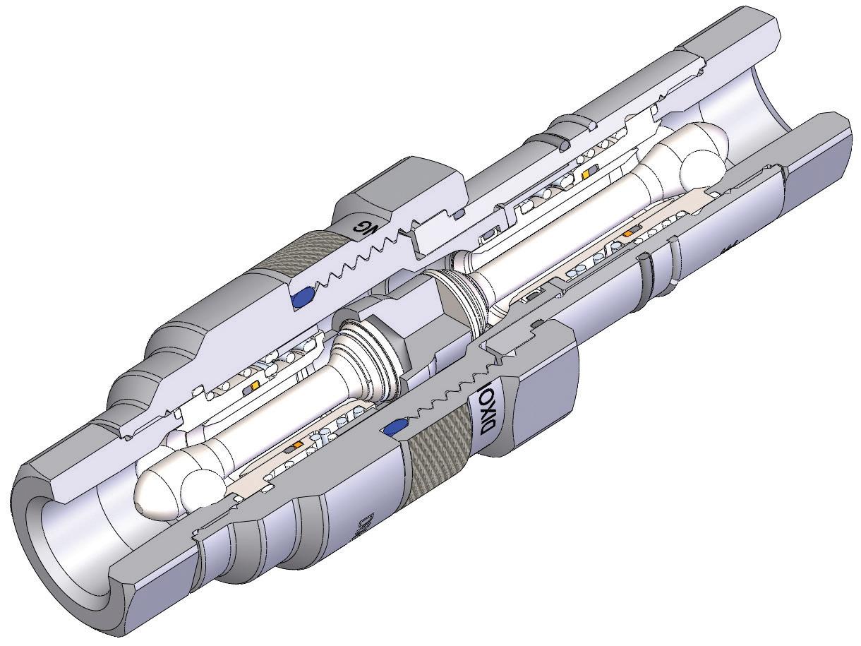
Two-stage valving to protect critical sealing components during pressurized connection and disconnection
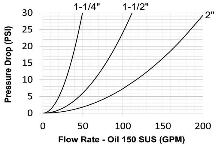
DORS retention system optimizes flow and impulse pressure performance
High-performance stem seals constructed of acetal or polyurethane
Posi-lock valve system secures valving during surge-flow conditions to prevent high-velocity damage
1Couplings impulse tested in accordance with ISO18869 for 1,000,000 cycles connected and 100,000 cycles disconnected at 133% of ISO working pressure.
2Couplings impulse tested in accordance with ISO18869 for 100,000 cycles connected and disconnected at maximum impulse pressure listed
3System temperature for maximum connect/disconnect
Hydraulic Couplings: VEP-Series
How to Connect and Disconnect the VEP-Series Coupling
1. Prior to connecting, thoroughly clean all mating surfaces and threads on both halves, then pull the coupler sleeve forward.
2. To initiate the connection, align the coupler and plug, pushing/turning the coupler sleeve toward the plug while engaging the threads. Keep the mating halves aligned during the connection process.
3. Allow the threads to pull the coupler onto the plug; do not push the coupler onto the plug.
4. The first phase of the connection should be threaded by hand, without the use of tools. Please note the connection sleeve may seize when dirt and debris accumulate in the threads - remove debris with a cloth, compressed air, or a brush.
5. The second phase of the connection may require a wrench if the pressure is higher than anticipated.
6. Continue to thread the coupler sleeve onto the plug until the end of the sleeve meets the plug body.
7. To disconnect, use a wrench to break the coupler sleeve free and keep the mating halves aligned during the disconnection process.
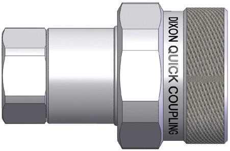
Body Size
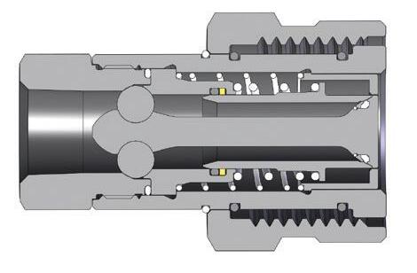
VEP-Series Coupler (Female Threads)
Hydraulic Couplings: VEP-Series
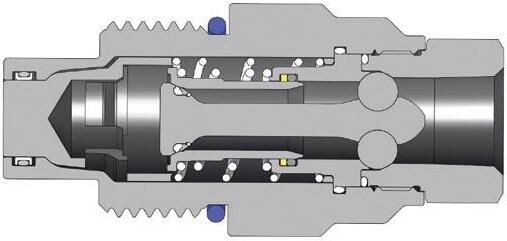
Body Size
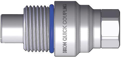
VEP-Series Plug (Female Threads)
Hydraulic Couplings: VEP-Series
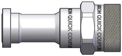
Body Size
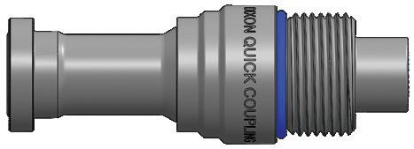
Body Size
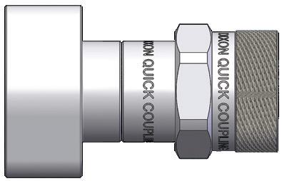
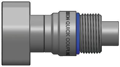
Body Size
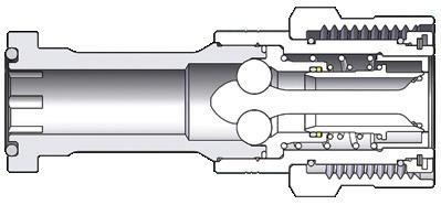
VEP-Series Code 62 Flange Head Coupler
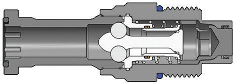
VEP-Series Code 62 Flange Head Plug
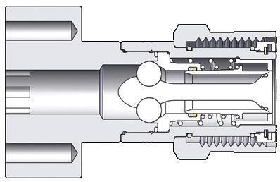
VEP-Series Code 62 Flange Pad Coupler
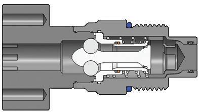
VEP-Series Code 62 Flange Pad Plug
Hydraulic Couplings: VEP-Series
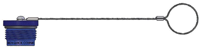
Body Size
1/4"
3/8"
1/2"
3/4"
1"
1-1/4"
1-1/2"
2"
Body Size
1/4"
3/8"
1/2"
3/4"
1"
1-1/4"
1-1/2"
2"
VEP-Series Rigid Dust Plug Part #
2VEPDP-A
3VEPDP-A
4VEPDP-A
6VEPDP-A
8VEPDP-A
10VEPDP-A
12VEPDP-A
16VEPDP-A
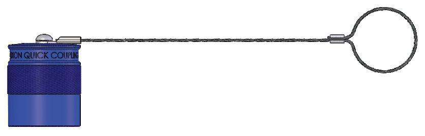
VEP-Series Rigid Dust Cap Part #
VEP2DC-A
VEP3DC-A
VEP4DC-A
VEP6DC-A
VEP8DC-A
VEP10DC-A
VEP12DC-A
VEP16DC-A
NOTE: VEP-Series dust caps and plugs are aluminum with a steel cable
VEP-Series Profile Body Size
Hydraulic Couplings: VEP-BOP-Series
Interchange Data
• Stucchi VEP/VEP-HD Series, DNP FSI-BOP-Series
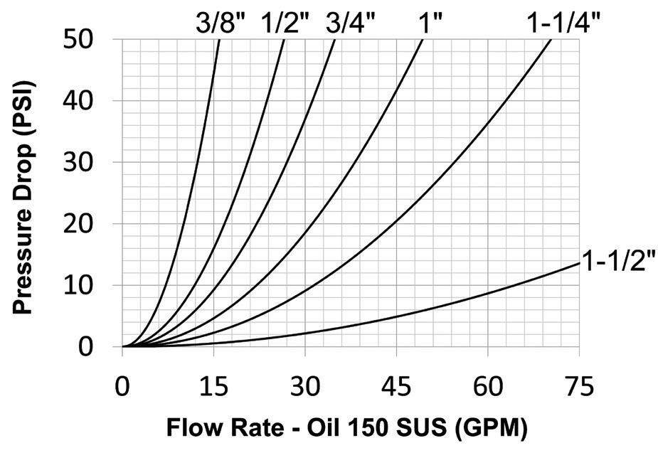
Seal Components
• Blowout preventer (BOP) coupling critical seals are severe service FKM
Materials
• Machined components are manufactured using solid steel bar stock
• Stainless steel retaining rings and springs maximize corrosion resistance and extend service life
• Steel components are plated using RoHS-compliant zinc nickel
• Red powder-coated components and external O-rings for easy BOP service identification
• BOP couplings have been fire tested and Lloyd's certified to 1300°F (700°C) in accordance with API 16D. Certificate available upon request.
• Use VEP dust caps and dust plugs found on page 144
Rated Pressure Chart
VEP-BOP-Series Interchange
ISO Working Max. Impulse Connected Coupler Plug
VEP-BOP-Series Profile
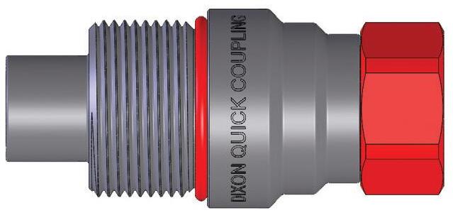
Hydraulic Couplings: VEP-BOP-Series
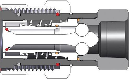
Body Size
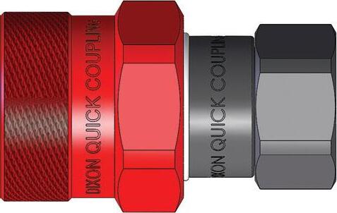
VEP-BOP-Series Blowout Preventer Safety Coupler (Female Threads)
Body Size
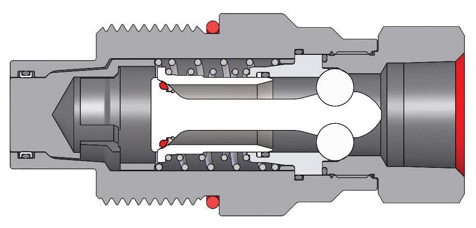
VEP-BOP-Series Blowout Preventer Safety Plug (Female Threads)
Hydraulic Couplings: W-Series
Interchange Data
• Eaton/Aeroquip 5100-Series, Parker 6100-Series
• Snap-Tite 78-Series, Faster Series-FB, Safeway S51-Series
Materials
• Machined components are manufactured using solid steel and brass bar stock
• Stainless steel retaining rings and springs maximize corrosion resistance and extend service life
• Steel componentry is plated using RoHS-compliant trivalent chrome
• Rugged steel wing nut for threaded connect and disconnect operation
• For steel models, coupler valve sleeve and plug valve are constructed of brass
Seal Components
• Nitrile seals are standard, providing a temperature range of -40°F to 250°F (-40°C to 121°C)
• Couplings have a TPC-ET back-up ring on the main coupler valve sleeve to extend service life
• Main coupler valve has a bonded face-seal to improve seal integrity during pressurized connection/disconnection
• Plug valve seal is crimped to improve seal integrity and prolong service life; 1-1/2" has bonded plug valve
• External O-ring on plug indicates full connection and acts as a contamination shield in connected mode
• Redundant O-ring on the coupler body will engage plug for secondary sealing support
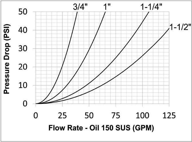
Rated Pressure Chart
Body Size
W-Series Wingstyle Interchange (Connected) Coupler/Plug
Technical Specifications
Although the wingstyle couplings are able to connect and disconnect while under pressure, it is recommended that hydraulic power supply be de-energized during connection to ensure operator safety. If it is not possible to de-energize the circuit, operators must be aware of their surroundings to ensure that an attachment or tool does not put them at risk, once hydraulic power is applied during the connection process.
NOTE: W-Series couplings are not recommended for continuous hydraulic impulse applications at rated pressures.
Hydraulic Couplings: W-Series
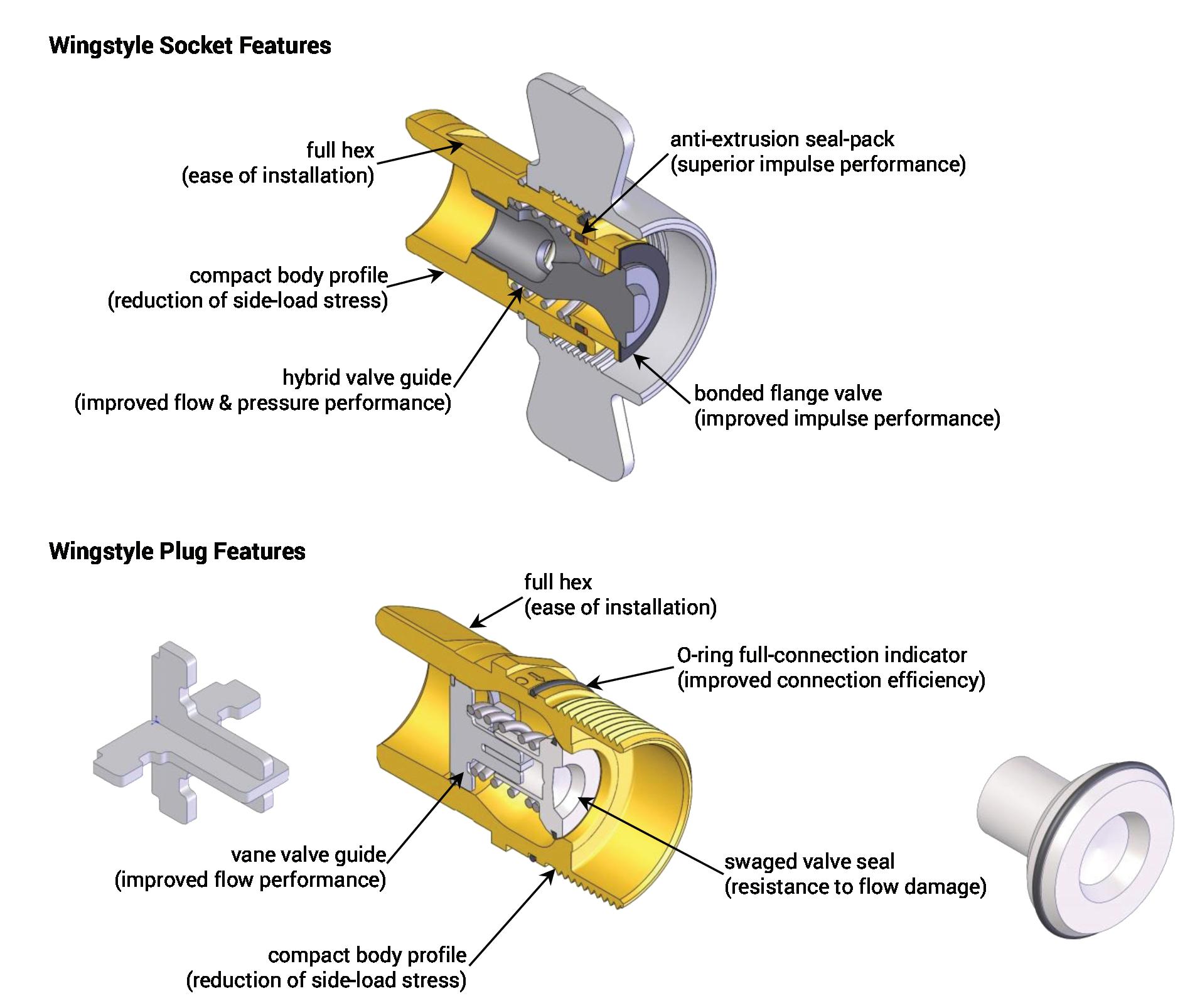
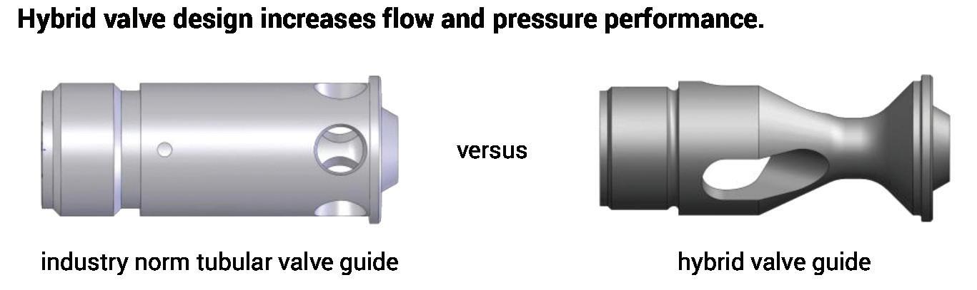
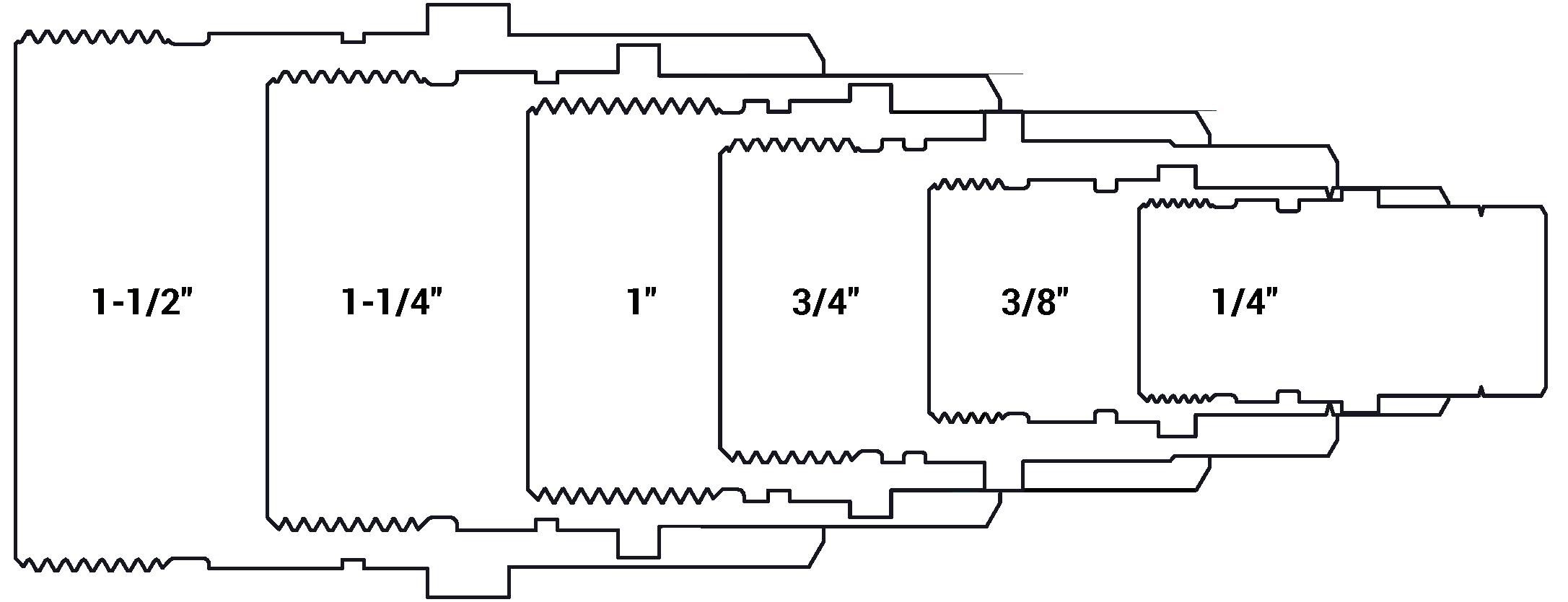
W-Series Profiles
Hydraulic Couplings: W-Series
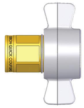
Body Size
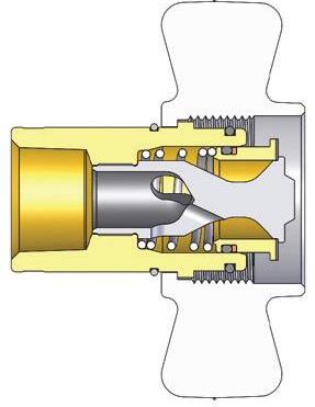
W-Series Wingstyle Interchange Coupler (Female Threads)
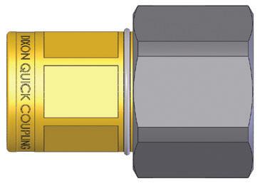
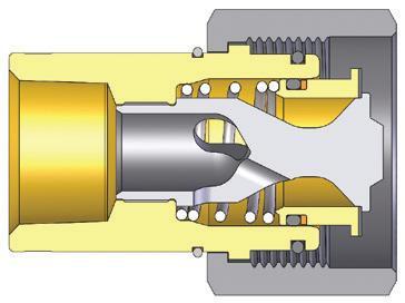
Hydraulic Couplings: W-Series
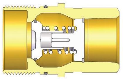
Body Size
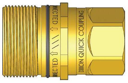
W-Series Wingstyle Interchange Plug (Female Threads)
Body Size
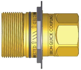
Plug not included with flange
W-Series Wingstyle Interchange Plug Mounting Flange
Hydraulic Couplings: W-Series
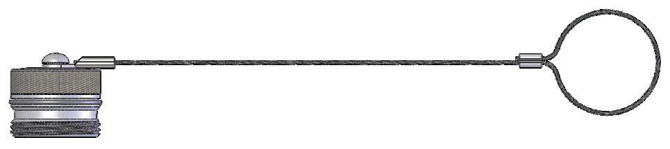
W-Series Wingstyle Interchange Coupler Rigid Dust Plug
Body Size
Part Detail Part #
1/4" 2WDP
3/8" 3WDP
3/4" 6WDP
1" 8WDP
1-1/4" 10WDP
1-1/2" 12WDP
Body Size
Body Size
cable
cable
cable
cable
cable
cable
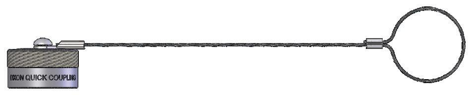
W-Series Wingstyle Interchange Plug Rigid Dust Cap
Part Detail
#
1/4" W2DC
3/8" W3DC
3/4" W6DC
1" W8DC
1-1/4" W10DC
1-1/2" W12DC
cable
cable
cable
cable
cable
W-Series Wingstyle Interchange Coupler Repair Kits
Part Detail
Part # Coupler Style Seal Material
Repair Kit Contents (for one coupler)
3/4" 6W-RKIT-V2 all Nitrile bonded valve, O-rings, and Hytrel® backup 1" 8W-RKIT-V2 all Nitrile bonded valve, O-rings, and Hytrel® backup
1-1/4" 10W-RKIT-V2 all Nitrile bonded valve, O-rings, and Hytrel® backup
1-1/2" 12W-RKIT-V2 all Nitrile bonded valve, O-rings, and Hytrel® backup
W-Series Wingstyle Interchange Plug Repair Kits
Body Size
Part Detail
Part # Coupler Style Seal Material
3/4" W6-RKIT-V2 all Nitrile
Repair Kit Contents (for one coupler)
valve assembly and O-ring 1" W8-RKIT-V2 all Nitrile
1-1/4" W10-RKIT-V2 all Nitrile
1-1/2" W12-RKIT-V2 all Nitrile
valve assembly and O-ring
valve assembly and O-ring
valve assembly and O-ring
Hydraulic Couplings: WS-Series
Interchange Data
• Parker/ Snap-Tite 75-Series, Hydraulics Inc. Series-5TV, DNP VFF-HD, Stucchi VOF, Faster OGV, Eaton FD85, Holmbury LC
Materials
• Machined components are manufactured using solid steel or 316 stainless steel bar stock
• Stainless steel retaining rings and springs maximize corrosion resistance and extend service life
• Steel componentry is plated using RoHS compliant zinc nickel for corrosion resistance
• Rugged high-strength steel sand-cast wing nut for threaded connect and disconnect operation
• 316 stainless steel plug connection-threads are coated to prevent galling during connection/disconnection
Seal Components
• Nitrile seals are standard, providing a temperature range of -40°F to 250°F (-40°C to 121°C)
• PTFE anti-extrusion ring protects main coupling O-ring from dynamic impulse pressure damage
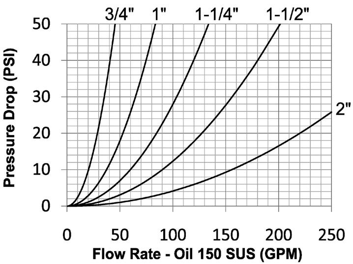
Rated Pressure Chart
WS-Series Heavy-Duty Wingstyle (Connected)
Body
Technical Specifications
Hydraulic Couplings: WS-Series
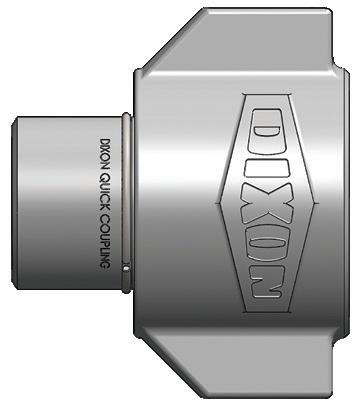
Body Size
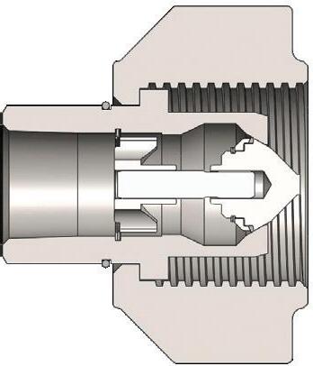
WS-Series Heavy-Duty Wingstyle Coupler (Female Threads)
2"
Hydraulic Couplings: WS-Series
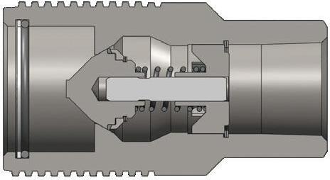
Body Size
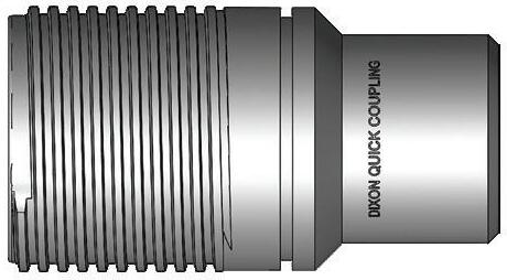
WS-Series Heavy-Duty Wingstyle Plug (Female Threads)
Hydraulic Couplings: WS-Series
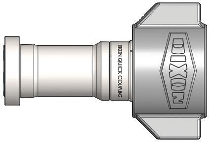
Body Size
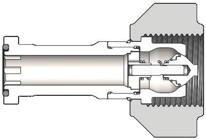
WS-Series Heavy-Duty Wingstyle Code 62 Flange Head Coupler
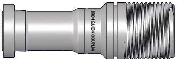
Body
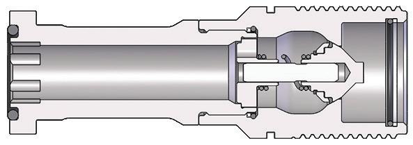
WS-Series Heavy-Duty Wingstyle Code 62 Flange Head Plug
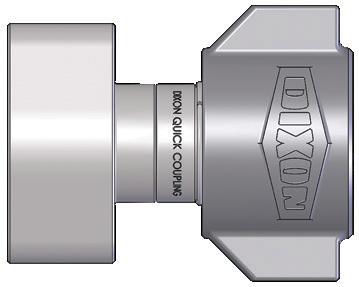
Body Size
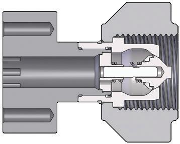
WS-Series Heavy-Duty Wingstyle Code 62 Flange Pad Coupler
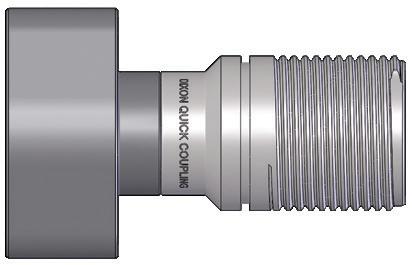
Body Size
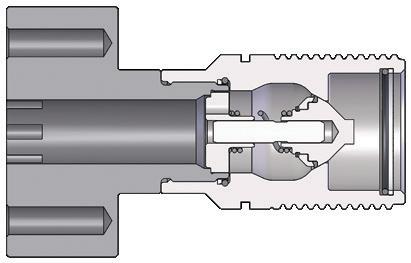
WS-Series Heavy-Duty Wingstyle Code 62 Flange Pad Plug
Hydraulic Couplings: WS-Series
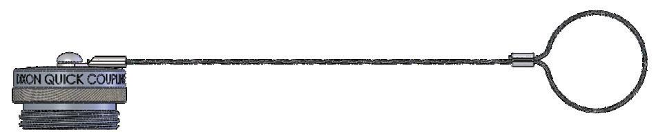
WS-Series Coupler Rigid Dust Plug
Body Size
Part #
3/4" 6WSDP-A steel cable
1" 8WSDP-A steel cable
1-1/4" 10WSDP-A steel cable
1-1/2" 12WSDP-A steel cable
2" 16WSDP-A steel cable
Part Detail
Body Size
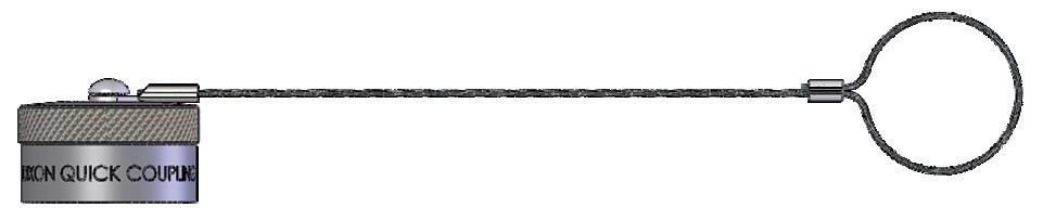
WS-Series Plug Rigid Dust Cap
Part Detail
Part
3/4" WS6DC-A steel cable
1" WS8DC-A steel cable
1-1/4" WS10DC-A steel cable
1-1/2" WS12DC-A steel cable
2" WS16DC-A steel cable
Hydraulic Couplings: WS-Series
Body Size
WS-Series Heavy-Duty Wingstyle Interchange Coupler Seal Kits
Part Detail Seal Kit Contents
Part # Coupler Style Seal Material
3/4" 6WS-SKIT all Nitrile
1" 8WS-SKIT all Nitrile
1-1/4" 10WS-SKIT all Nitrile
1-1/2" 12WS-SKIT all Nitrile
2" 16WS-SKIT all Nitrile
Body Size
body / valve seals and retaining rings
body / valve seals and retaining rings
body / valve seals and retaining rings
body / valve seals and retaining rings
body / valve seals and retaining rings
WS-Series Heavy-Duty Wingstyle Interchange Coupler Repair Kits
Part # Coupler Style Seal Material
Part Detail Repair Kit Contents (for one coupler or plug)
3/4" 6WS-RKIT all Nitrile valve assembly, O-ring, and PTFE B.U.
1" 8WS-RKIT all Nitrile
valve assembly, O-ring, and PTFE B.U.
1-1/4" 10WS-RKIT all Nitrile valve assembly, O-ring, and PTFE B.U.
1-1/2" 12WS-RKIT all Nitrile valve assembly, O-ring, and PTFE B.U.
2" 16WS-RKIT all Nitrile valve assembly, O-ring, and PTFE B.U.
Hydraulic Couplings: WS-BOP-Series
Interchange Data
• Parker/Snap-Tite 75-Series, DNP VFF-HD BOP-Series
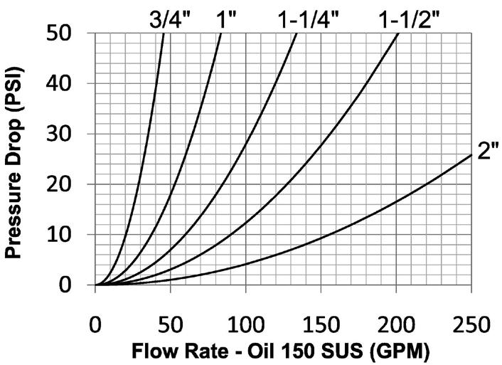
Seal Components
• Blowout preventer (BOP) couplings contain severe service FKM seals
• PTFE anti-extrusion ring protects main coupling valve seal from dynamic impulse pressure damage
Materials
• Machined components are manufactured using solid steel or 316 stainless steel bar stock
• Stainless steel retaining rings and springs maximize corrosion resistance and extend service life
• Steel componentry is plated using RoHS-compliant zinc nickel
• Rugged high-strength steel wing nut for threaded connect and disconnect operation
• 316 stainless steel plug connection-threads are coated to prevent galling during connection/disconnection
• Red powder-coated coupler wing-nut and external plug O-ring for easy BOP service identification
• BOP couplings have been fire tested and Lloyd's certified to 1300°F (700°C) in accordance with API 16D. Certificate available upon request.
• Use WS dust caps and dust plugs found on page 156
Rated Pressure Chart
WS-BOP-Series Blowout Preventer Heavy-Duty Wingstyle
Body
Steel Coupler/Plug
Technical Specifications
316 SS Coupler/Plug
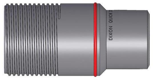
Hydraulic Couplings: WS-BOP-Series
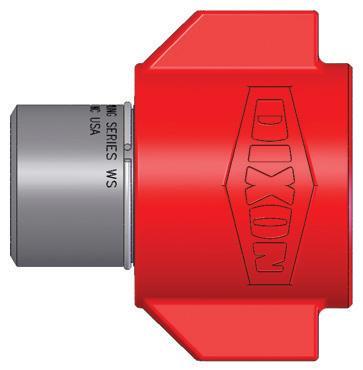
Body Size
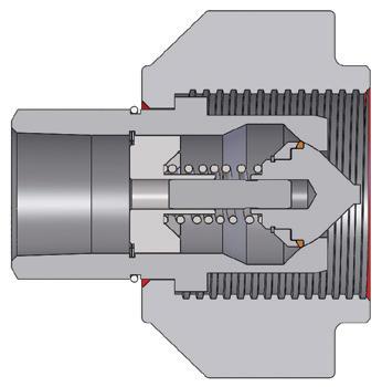
WS-BOP-Series Blowout Preventer Safety Coupler (Female Threads)
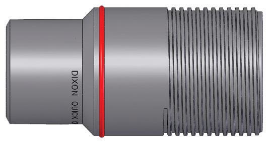
Body Size
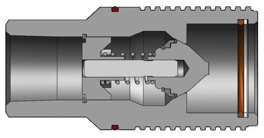
WS-BOP-Series Blowout Preventer Safety Plug (Female Threads)
Body Size
WS-Series BOP Wingstyle Interchange Coupler Seal Kits
1-1/4" 10BOP-SKIT all FR FKM body / valve seals and retaining rings
1-1/2" 12BOP-SKIT all FR FKM body / valve seals and retaining rings
2" 16BOP-SKIT all FR FKM body / valve seals and retaining rings
Hydraulic Couplings: T-Series
Interchange Data
• High-pressure 10K thread-together interchange
• Parker/Pioneer 3000-Series, Enerpac C604, Stucchi IVHP
• Eaton WS56000 and DNP PVM
• Interchangeable to ISO 14540
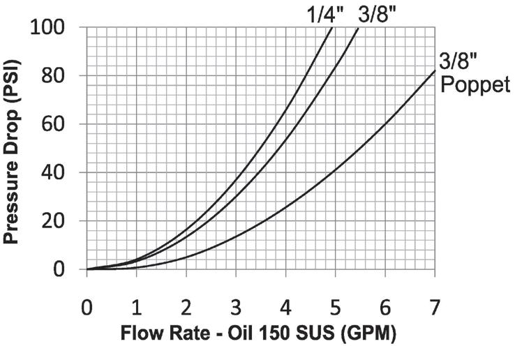
Seal Components
• Nitrile O-ring with TPC-ET back-up ring is standard, providing a temperature range of -40°F to 250°F (-40°C to 121°C)
Materials
• Machined components are manufactured using solid steel or 316 stainless steel bar stock
• Chrome steel ball valve is mechanically seated to improve pressure sealing performance
• Steel plugs are machined from solid high strength steel bar stock
• Steel componentry is plated using RoHS-compliant trivalent chrome
Technical Specifications
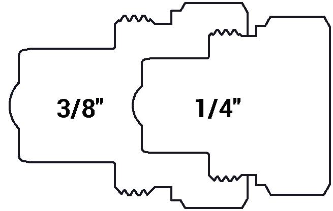
Hydraulic Couplings: T-Series
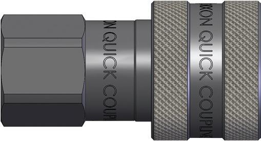
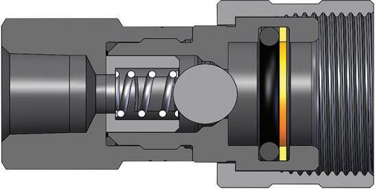
T-Series 10K Threaded Ball Coupler (Female Threads)
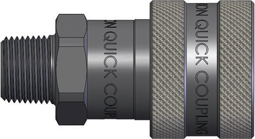
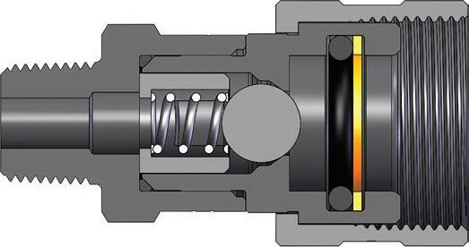
T-Series 10K Threaded Ball Coupler (Male Threads)
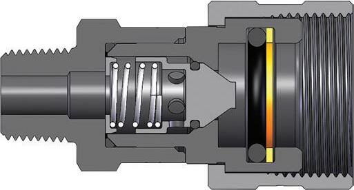
T-Series 10K Threaded Poppet Coupler (Male Threads)
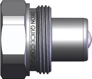
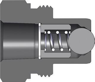
T-Series 10K Threaded Ball Plug (Female Threads)
Hydraulic Couplings: T-Series
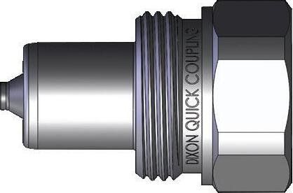
Body Size
Body Size
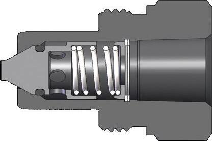
T-Series 10K Threaded Poppet Plug (Female Threads)
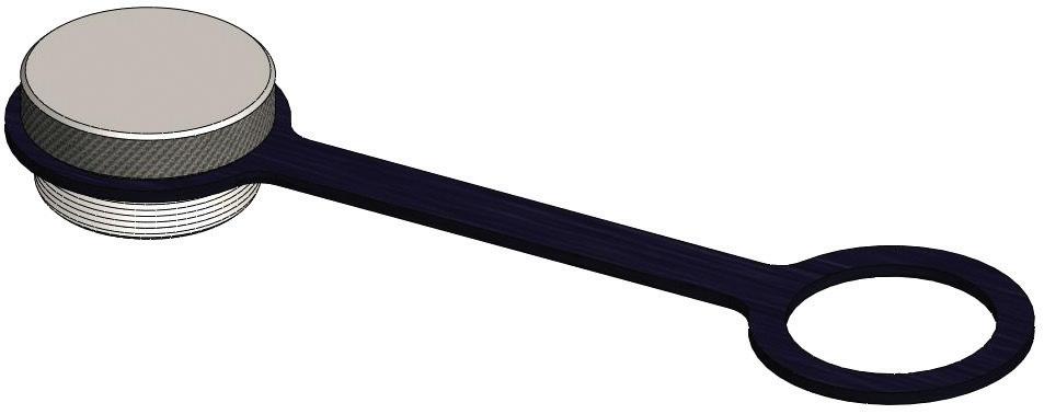
T-Series Coupler Rigid Dust Plug
Detail
1/4" 2TDP rubber
3/8" 3TDP rubber
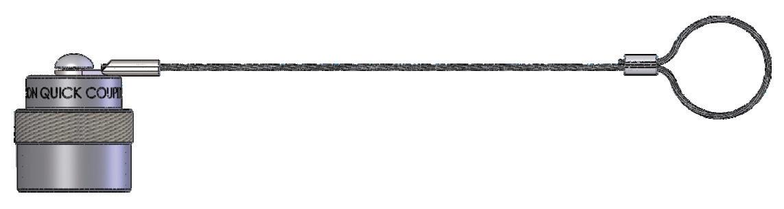
T-Series Plug Rigid Dust Cap
Body Size
Part Detail Part # Lanyard
1/4" T2DC steel cable
3/8" T3DC steel cable
T-Series 10K Threaded Coupler Seal Kits
Body Size
Part Detail Seal Kit Contents
Part # Coupler Style Seal Material
1/4" 2T-SKIT ball valve Nitrile Nitrile o-ring with TPC-ET back-up ring
3/8" 3T-SKIT ball valve Nitrile Nitrile o-ring with TPC-ET back-up ring
NOTE: 3T-SKIT will only work with the 3TF3 and 3TM3 parts not the 3TF3-SS, 3TM3-SS or 3TM3-SS-PV.
Hydraulic Couplings: CVV-Series
Interchange Data
• Interchangeable with ISO14541 1/4" - 3/4"
• European screw-together interchange
• Inteva STG-Series, Faster CVV-Series, DNP PVV3, Voswinkel Type-HS
Materials
• Machined components are manufactured using solid steel bar stock
• Steel retaining rings and springs maximize service life in rugged environments
• Steel componentry is plated using RoHS-compliant trivalent chrome
Seal Components
• Nitrile seals are standard, providing a temperature range of -13°F to 257°F (-25°C to 125°C)
• Plugs have a PTFE anti-extrusion ring to prevent O-ring damage during dynamic impulse service
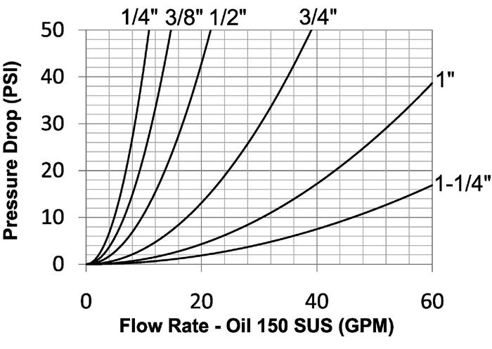
Rated Pressure Chart
CVV-Series European Screw-Together Interchange Coupler/Plug Coupled
NOTE: Threaded sleeves enable easy connection and disconnection while system is under residual pressure only. Body Size
Technical Specifications
Hydraulic Couplings: CVV-Series
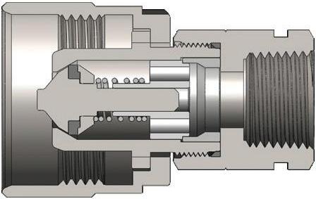
Body Size
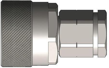
CVV-Series European Interchange Coupler (Female Threads)
Hydraulic Couplings: CVV-Series
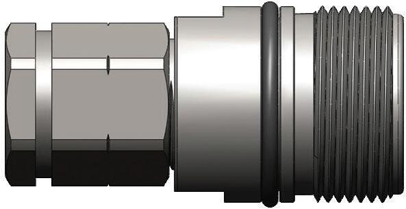
Body Size
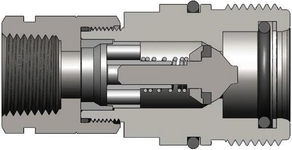
CVV-Series European Interchange Plug (Female Threads)
Hydraulic Couplings: CVV-Series

CVV-Series European Interchange Dust Plug
Body Size
1/4" 2CVVDP
3/8" 3CVVDP
1/2" 4CVVDP
Part Detail
3/4" 6CVVDP plastic plastic 1" 8CVVDP plastic plastic
1-1/4" 10CVVDP

CVV-Series European Interchange Dust Cap
Body Size
1/4" CVV2DC
3/8" CVV3DC
1/2" CVV4DC
Part Detail
Body Size
3/4" CVV6DC plastic plastic
1" CVV8DC plastic plastic
1-1/4" CVV10DC plastic plastic
CVV-Series Profiles
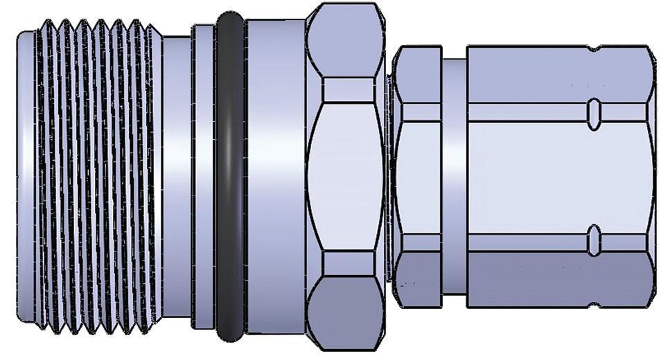
Hydraulic Couplings: TD-Series
Interchange Data
• Spir Star CQD-Series, DNP CRS-Series, Jetstream Screw Type
Materials
• Machined components are manufactured using 316 stainless steel bar stock
• Stainless steel retaining rings maximize corrosion resistance and extend service life
• Nitrile seals are standard, providing a temperature range of -40°F to 250°F (-40°C to 121°C)
• Couplers have a Nitrile anti-extrusion ring, providing resistance to O-ring dynamic impulse pressure damage
Rated Pressure Chart
TD-Series 15K and 20K Threaded Couplings
Body Size
Maximum Working
Technical Specifications
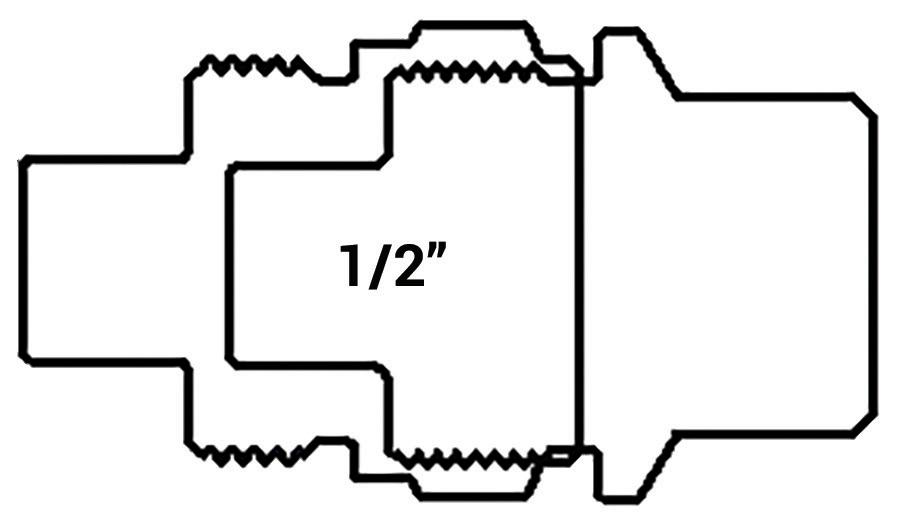
Hydraulic Couplings: TD-Series
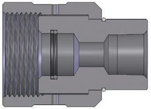
Body Size
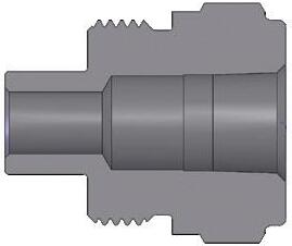
Body Size
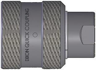
TD-Series 15K Threaded Coupler (Female Threads)
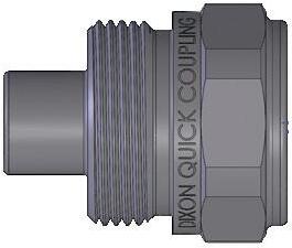
TD-Series 15K Threaded Plug (Female Threads)
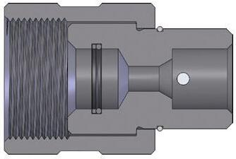
Body Size
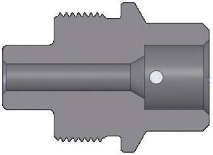
Body Size
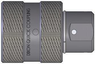
TD-Series 20K Threaded Coupler (Female MP Threads)
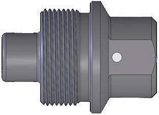
TD-Series 20K Threaded Plug (Female MP Threads)
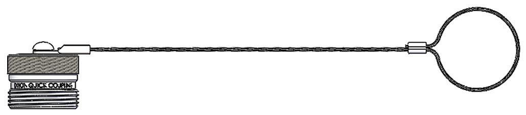
Body Size
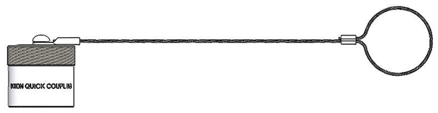
TD-Series Dust Cap and Dust Plug
Hydraulic Couplings: E-Series
Interchange Data
• Straight-through pressure-wash interchange
• Parker ST-Series, Foster FST-Series, Hansen ST-Series
Seal Components
• Nitrile seals are standard, providing a temperature range of -40°F to 250°F (-40°C to 121°C)
Materials
• Machined components are manufactured using solid steel, brass, or 303 stainless steel bar stock
• Stainless steel balls, retaining rings, and springs maximize corrosion resistance and extend service life
• Steel componentry is plated using RoHS-compliant trivalent chrome
• 1-1/4" to 2" brass couplers have steel sleeves as standard to maximize service life, hardened to resist deformation
• Steel plugs are hardened to provide heavy-duty performance
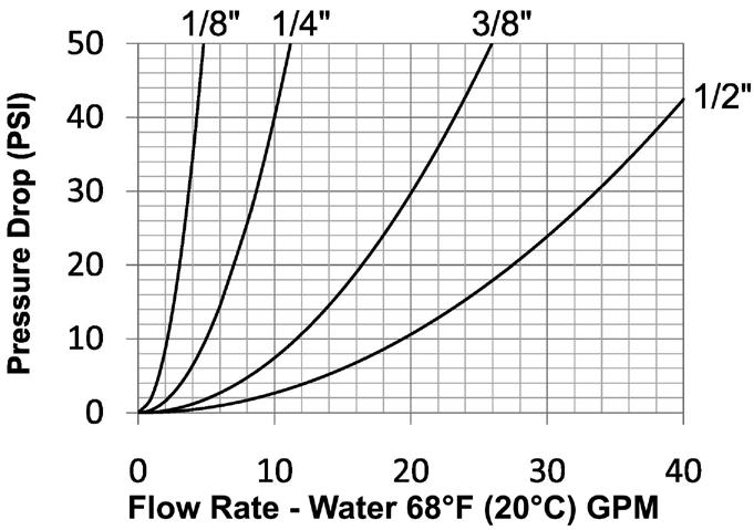
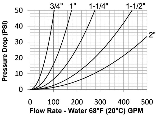
Rated Pressure Chart
Straight-Through Interchange (Connected)
Body Size
Technical Specifications
Hydraulic Couplings: E-Series
Available Options
3/4" F-
1-1/4" F-
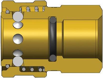
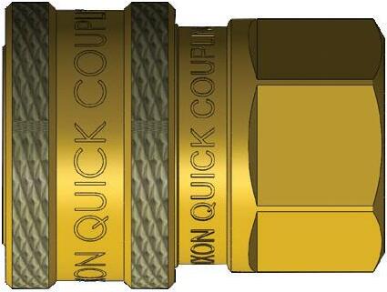
Body Size E-Series Straight-Through Interchange Coupler (Female Threads)
Hydraulic Couplings: E-Series
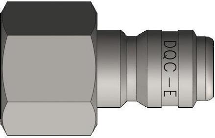
Body Size
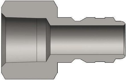
E-Series Straight-Through Interchange Plug (Female Threads)
Hydraulic Couplings: E-Series
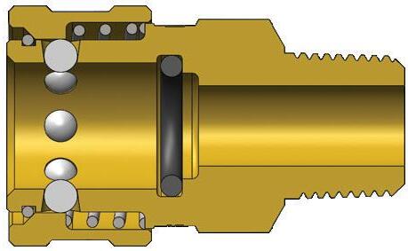
Body Size
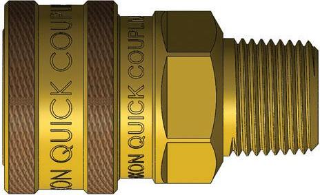
E-Series Straight-Through Interchange Coupler (Male Threads)
Body Size A B
1/8" 0.26 0.08 1/4" 0.40 0.11 3/8" 0.49 0.13 1/2" 0.64 0.13 3/4" 0.89 0.17
E-Series Profiles
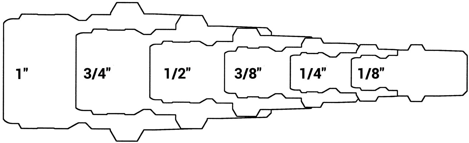
Hydraulic Couplings: E-Series
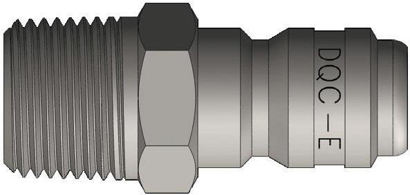
Body Size
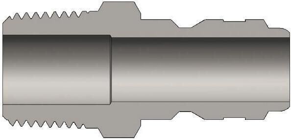
E-Series Straight-Through Interchange Plug (Male Threads)
Body Size
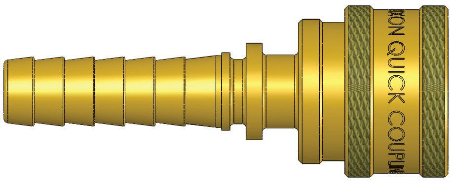
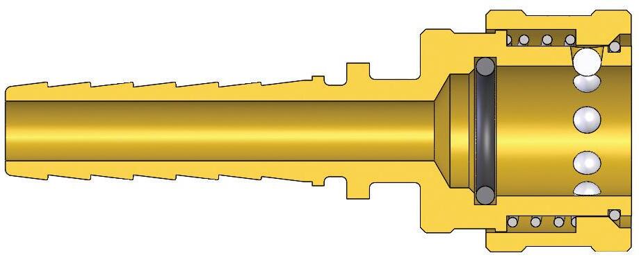
E-Series Straight-Through Interchange Coupler (Hose Barb)
Hydraulic Couplings: E-Series
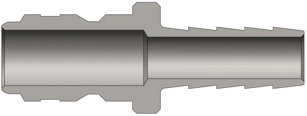
Body Size
1/4"
3/8"
1/2"
3/4"
1"
1-1/4"
1-1/2"
2"
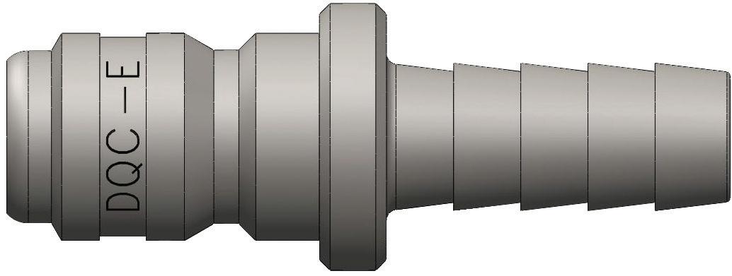
E-Series Straight-Through Interchange Plug (Hose Barb)
E-Series Straight-Through Interchange Coupler Seal Kits
2E-SKIT all Nitrile body O-ring
F-2E-SKIT all FKM body O-ring
P-2E-SKIT all EPDM body O-ring
3E-SKIT all Nitrile body O-ring
F-3E-SKIT all FKM body O-ring
P-3E-SKIT all EPDM body O-ring
4E-SKIT all Nitrile body O-ring
F-4E-SKIT all FKM body O-ring
P-4E-SKIT all EPDM body O-ring
6E-SKIT all Nitrile body O-ring
F-6E-SKIT all FKM body O-ring
P-6E-SKIT all EPDM body O-ring
8E-SKIT all Nitrile body O-ring
F-8E-SKIT all FKM body O-ring
P-8E-SKIT all EPDM body O-ring
10E-SKIT all Nitrile body O-ring
F-10E-SKIT all FKM body O-ring
P-10E-SKIT all EPDM body O-ring
12E-SKIT all Nitrile body O-ring
F-12E-SKIT all FKM body O-ring
P-12E-SKIT all EPDM body O-ring
16E-SKIT all Nitrile body O-ring
F-16E-SKIT all FKM body O-ring
P-16E-SKIT all EPDM body O-ring
Hydraulic Couplings: EA-Series
Interchange Data
• Water-blast Interchange
• Parker Series-WB and Eaton/Aeroquip FD69
• Couplers have a PTFE anti-extrusion ring, providing resistance to O-ring dynamic impulse pressure damage Seal Components
• Nitrile seals are standard, providing a temperature range of -40°F to 250°F (-40°C to 121°C)
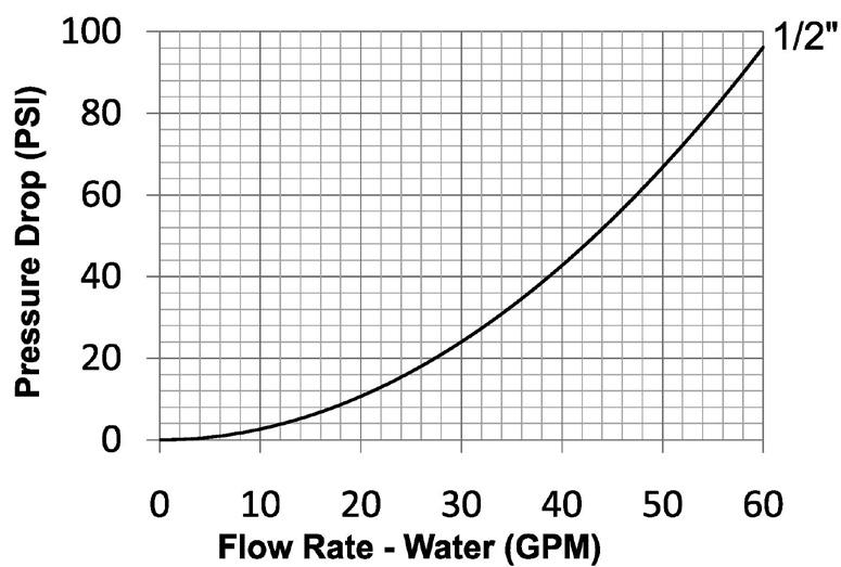
Materials
• Machined components are manufactured using solid high strength steel bar stock
• Stainless steel springs and retaining rings maximize corrosion resistance and extend service life
• Latches are manufactured from high-strength steel and plated with electroless nickel
• Steel plugs are machined from solid high strength steel bar stock and hardened
• Machined steel componentry is plated using RoHScompliant trivalent chrome
Rated Pressure Chart
EA-Series Water-Blast Interchange (Connected)
Body Size
Coupler/Plug
Technical Specifications
Body
Available Options
Hydraulic Couplings: EA-Series
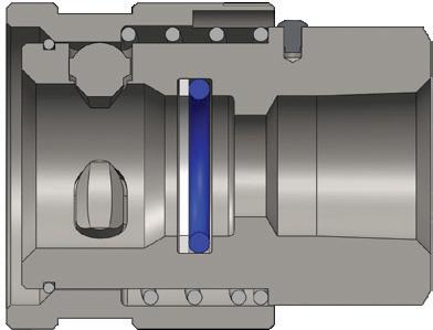
Body Size
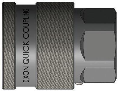
EA-Series Water-Blast Interchange Coupler (Female Threads)
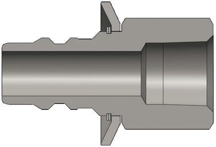
Body Size
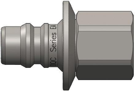
EA-Series Water-Blast Interchange Plug (Female Threads)
Body Size
EA-Series Water-Blast Interchange Coupler Seal Kits
4EA-SKIT all Nitrile body O-ring and PTFE back-up
F-4EA-SKIT all FKM body O-ring and PTFE back-up
P-4EA-SKIT all EPDM body O-ring and PTFE back-up
EA-Series Profile
Hydraulic Couplings: CM-Series
Interchange Data
• Mold coolant interchange
• Foster Series-FJT, Hansen Flo-Temp, Parker Moldmate, DME Jiffy-Tite
Seal Components
• Silicon gaskets and valve O-rings are standard, providing a temperature range of -90°F to 400°F (-68°C to 205°C)
Materials
• Machined components are manufactured using solid steel or brass bar stock
• Stainless steel balls, retaining rings, and springs maximize corrosion resistance and extend service life
• Steel componentry is plated using RoHS-compliant trivalent chrome
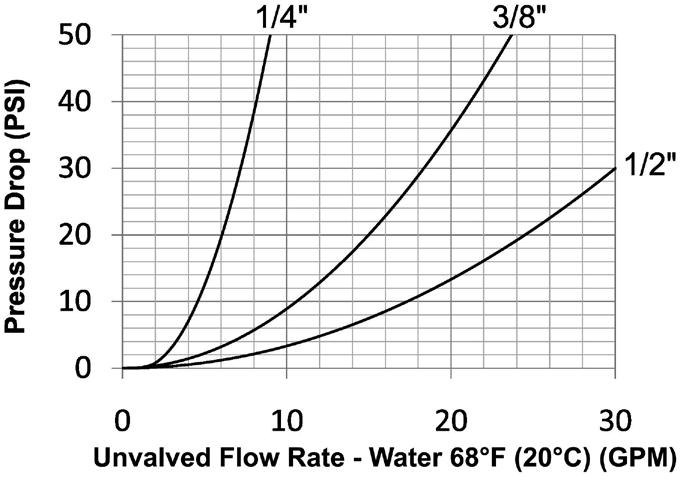
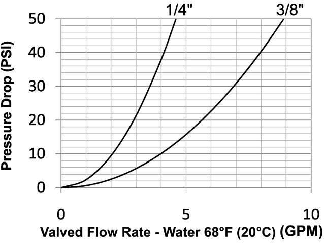
Rated Pressure Chart
CM-Series Industrial Mold Interchange (Connected)
Body Size
Unvalved Coupler/Brass Plug Unvalved Coupler/Steel Plug Valved Coupler/Brass Plug Valved Coupler/Steel Plug
Technical Specifications
CM-Series Profiles
Hydraulic Couplings: CM-Series
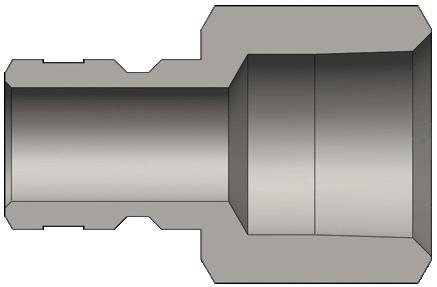
Body Size
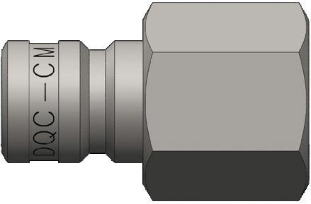
CM-Series Industrial Mold Interchange Plug (Female Threads)
Body Size
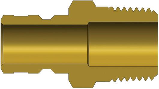
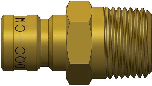
CM-Series Industrial Mold Interchange Plug (Male Threads)
Hydraulic Couplings: CM-Series

Body
Size

CM-Series Industrial Mold Interchange Extension Plug (Male Threads)
- 27
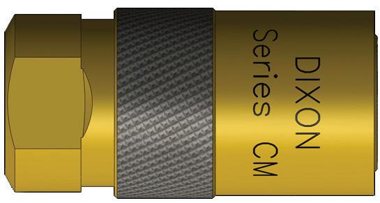
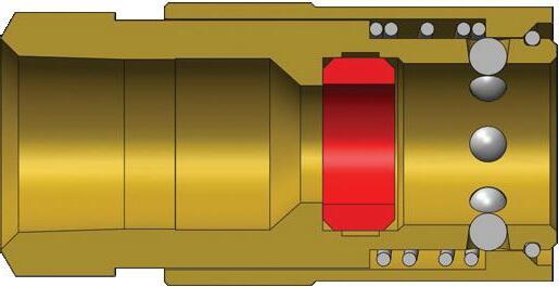
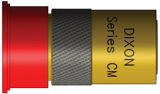
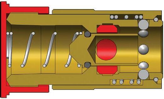
CM-Series Industrial Mold Interchange Valved Coupler (Female Threads)
Hydraulic Couplings: CM-Series
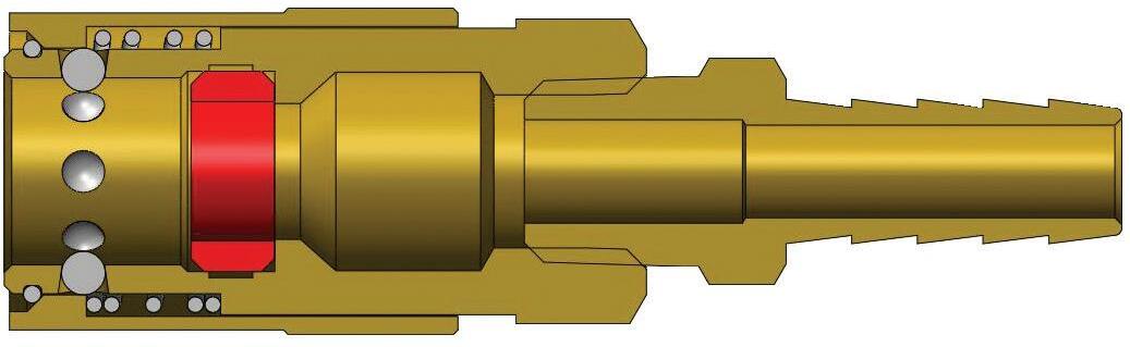
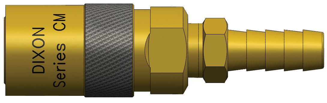
Body Size
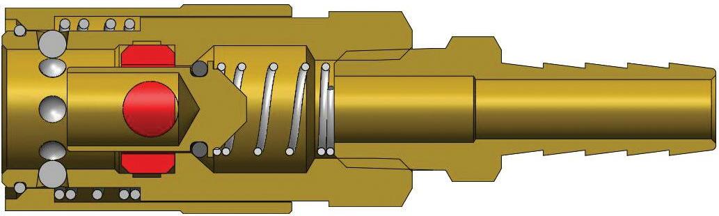
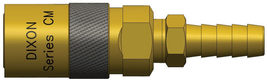
Body Size
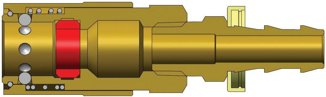
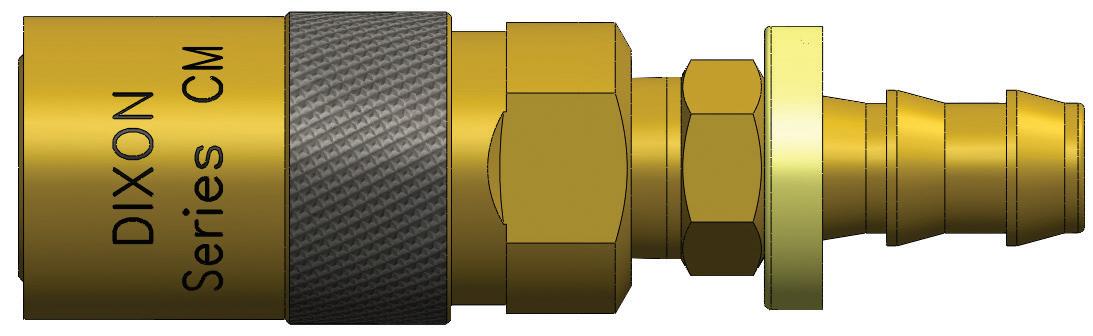
CM-Series Industrial Mold Interchange Unvalved Coupler (Hose Barb)
CM-Series Industrial Mold Interchange Valved Coupler (Hose Barb)
CM-Series Industrial Mold Interchange Unvalved Coupler (Push-Loc Barb)
Hydraulic Couplings: CM-Series
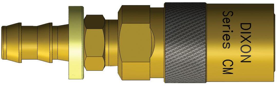
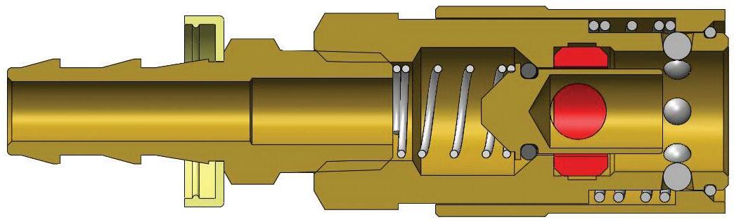
CM-Series Industrial Mold Interchange Valved Coupler (Push-Loc Barb)
Body Size
Body Size
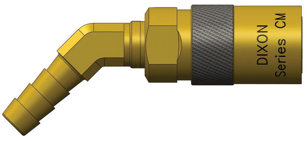
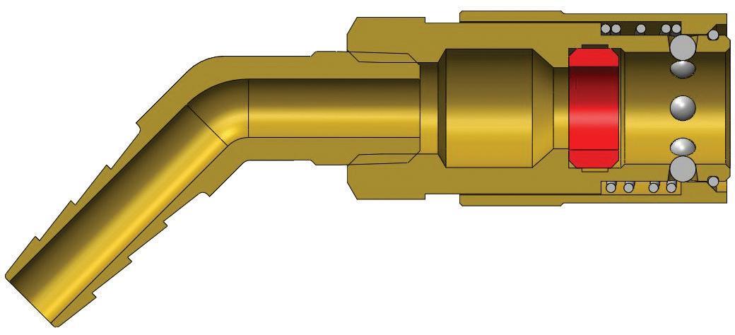
CM-Series Industrial Mold Interchange Unvalved Coupler (45º Hose Barb)
Body Size
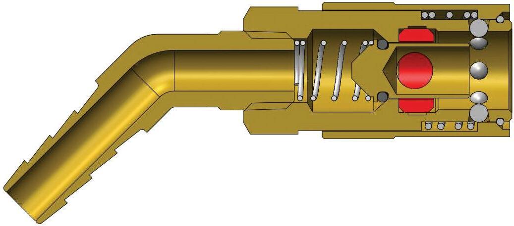
CM-Series Industrial Mold Interchange Valved Coupler (45º Hose Barb)
Hydraulic Couplings: CM-Series
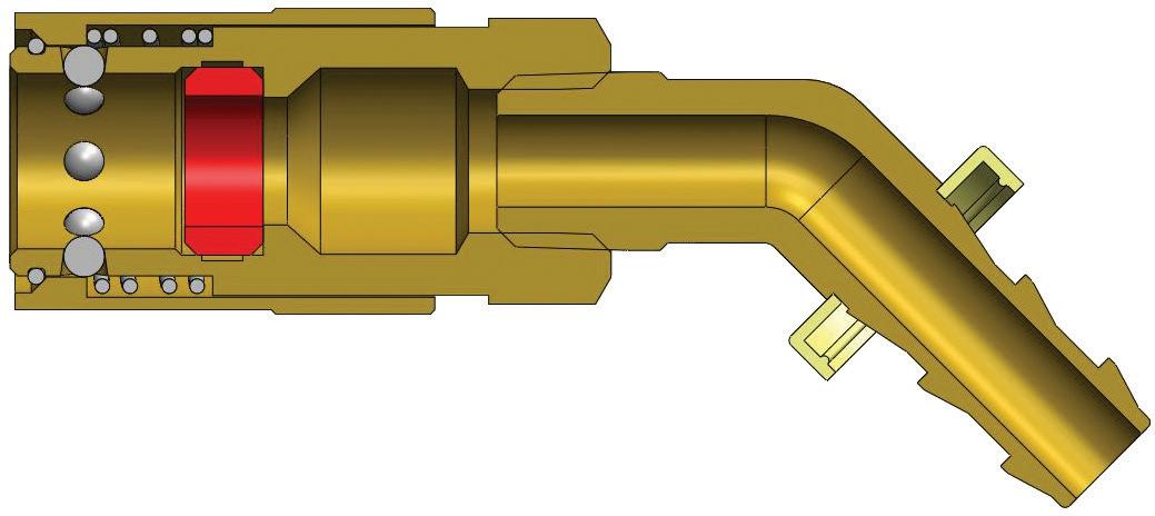
Body Size
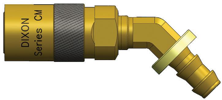
CM-Series Industrial Mold Interchange Unvalved Coupler (45º Push-Loc Barb)
Body Size
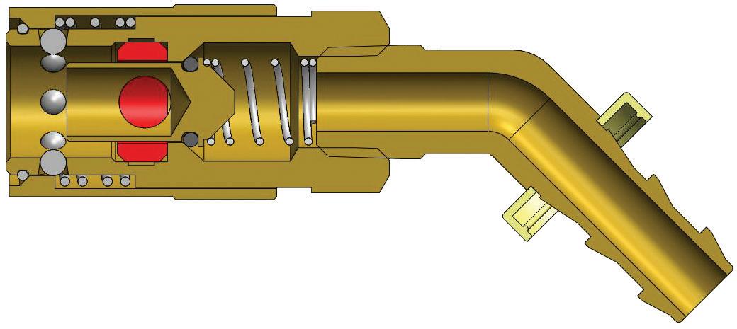
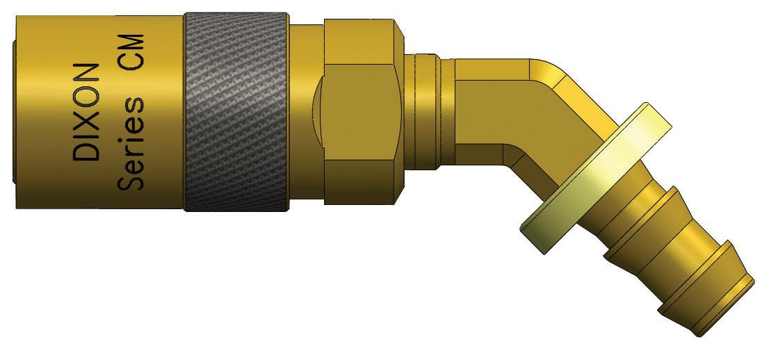
CM-Series Industrial Mold Interchange Valved Coupler (45º Push-Loc Barb)
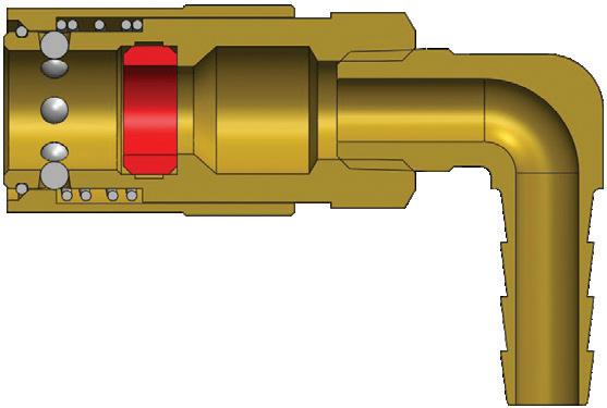
Body Size
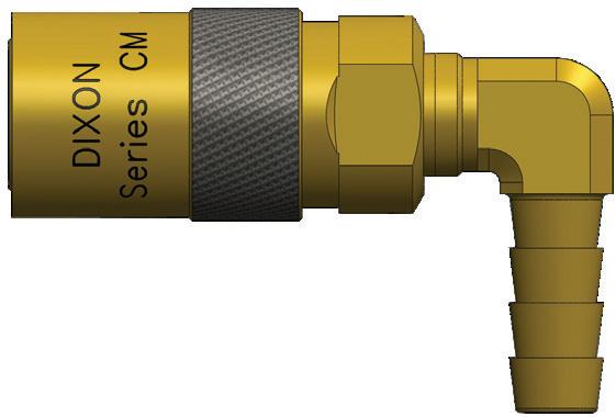
CM-Series Industrial Mold Interchange Unvalved Coupler (90º Hose Barb)
Hydraulic Couplings: CM-Series
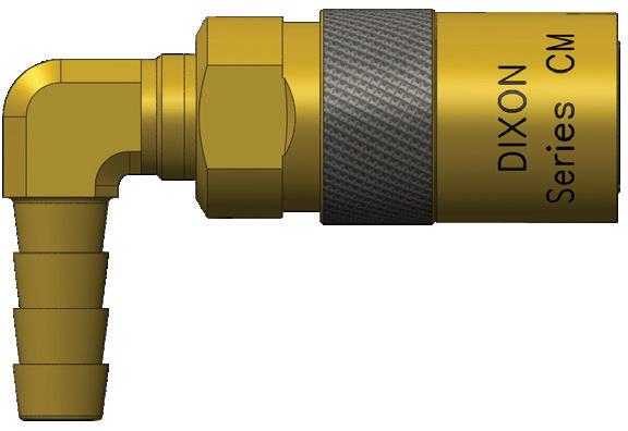
Body Size
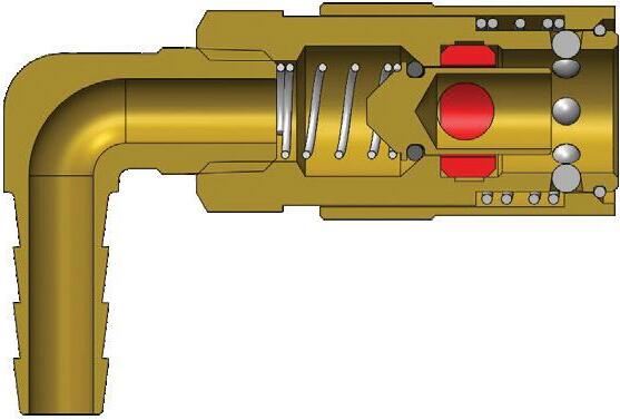
CM-Series Industrial Mold Interchange Valved Coupler (90º Hose Barb)
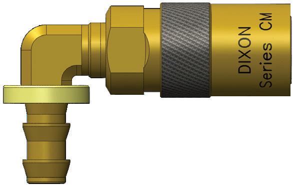
Body Size
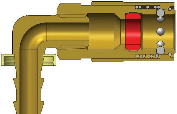
CM-Series Industrial Mold Interchange Unvalved Coupler (90º Push-Loc Barb)
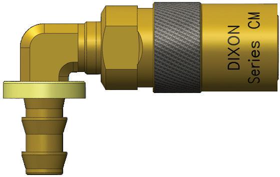
Body Size
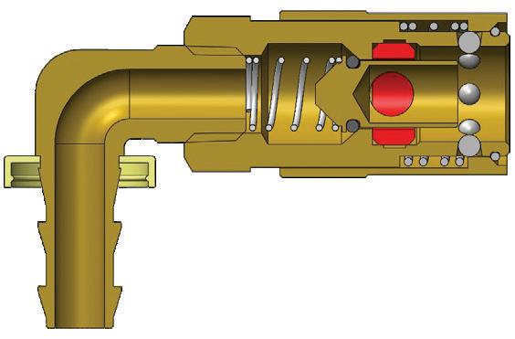
CM-Series Industrial Mold Interchange Valved Coupler (90º Push-Loc Barb)
Hydraulic Couplings: CM-Series
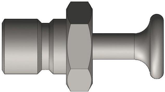
Body Size
CM-Series Coupler Rigid Dust Plug Part Detail
1/4" 2CMPC-B N/A
3/8" 3CMPC-B N/A
1/2" 4CMPC-B N/A
CM-Series Industrial Mold Interchange Coupler Seal Kits
Body Size
Part Detail
Part # Coupler Style Seal Material
Seal Kit Contents
1/4" 2CM-SKIT all Silicone body seal
3/8" 3CM-SKIT all Silicone body seal
1/2" 4CM-SKIT all Silicone body seal
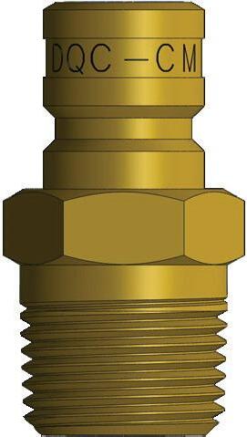
Counterbored mold ports will protect the male threaded plug, allowing the plug to be mounted below the surface, simplifying storing and handling of molds. Dixon male threaded plugs are constructed of corrosion resistant brass to maximize longevity in moist environments.
Body Size
3/8"
Interchange Data
• Designed to ISO 7241-B Series profile
• Interchangeable with Oasis 300-Series
• Interchangeable with Eclipse VQ-Series Materials
• Machined components are manufactured using 303 stainless steel bar stock
• Stainless steel springs and retaining rings maximize corrosion resistance and extend service life
• Latches are manufactured from high strength 17-7 stainless steel
• Locking sleeve is standard
• Nitrile rubber dust cap standard with plugs
• CRN number 0A24883.C
Seal Components
• FKM seals are standard, providing a temperature range of -65°F to 400°F (-54°C to 204°C)
• Coupler has redundant O-ring sealing system with PTFE back-up ring
• Valve has captured O-ring to maintain integrity during excessive flow conditions and pressured connections
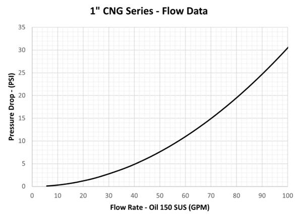
Rated Pressure Chart
Body Size
1 Flow calculated with CV value with water testing
Technical
Specifications
Body Size
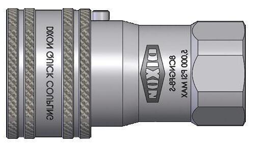
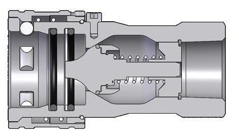
CNG-Series Compressed Natural Gas Coupler (Female Threads)
Detail
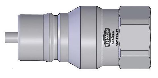
Body Size
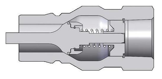
CNG-Series Compressed Natural Gas Plug (Female Threads)
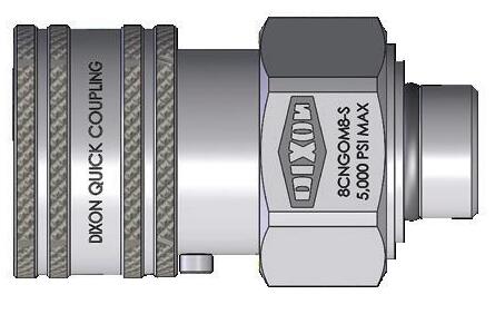
Body Size
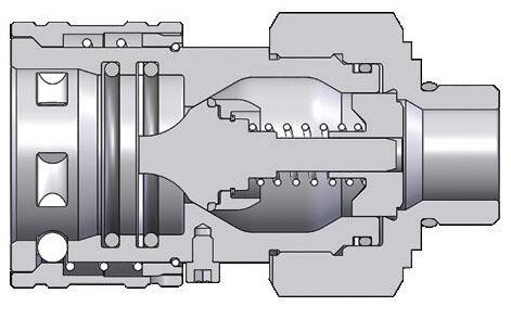
CNG-Series Compressed Natural Gas Coupler (Male Threads)
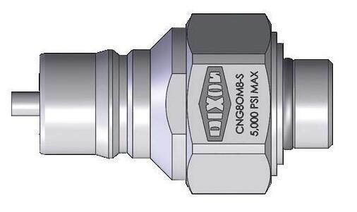
Body Size
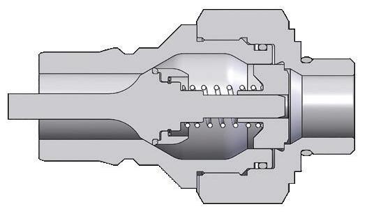
CNG-Series Compressed Natural Gas Plug (Male Threads)
CNG-Series
Seal and Repair Kits
Body Size Part # Coupler Material Seal Material Repair Kit Contents (For one coupler or plug)
8CNG-SKIT - V2 303 SS FKM back-up ring, body O-Rings
1"
8CNG-SRKIT - V2 303 SS FKM socket valve assembly, retaining ring, valve spring, valve guide, and all required O-Rings
CNG8-SRKIT - V2 303 SS FKM socket valve assembly, retaining ring, valve spring, valve guide, and all required O-Rings
Alpha Numeric Product Index
#
1AF1-B ................................ 65
1AM1-B 66
1AS1-B 66
1BRBF1-B-7 63
1BRBF2-B-7 63
1BRF1-B-7 63
1BRF2-B-7 63
1BRGM1-B-7 64
1BRGM2-B-7 64
1BRM1-B-7 64
1BRM2-B-7 64
1BRS1.25-B-7 64
1BRS1.86-B-7 64
1BRS2.83-B-7 64
1EF1-B 170
1EF1-S 170
1EM1-B ............................. 172
1EM1-S 172
1HDP 77, 109
1HF1 ................................... 71
1HF1-B 71
1HF1-S 71
1HF1-SS .............................. 71
1HOF2 71
1H-SKIT 78
1PDF1 ............................... 138 1PDF2 138 1PDM2 139
2AE2-B ................................ 67
2AF1-B 65
2AF2-B 65
2AGDP ................................ 94
2AGF2 92
2AGF2-PV 92
2AM1-B ............................... 66
2AM2-B 66
2AS2-B 66
2CJBM2-B ........................... 40
2CJBM3-B 40
2CJM2-B 40
2CJM3-B ............................. 40
2CM4B2-B 182
2CM4B2-B-E 182
2CM4B3-B ......................... 182
2CM4B3-B-E 182
2CM4S2.5-B 181
2CM4S2.5-B-E 181
2CM4S2-B 181
2CM4S2-B-E 181
2CM4S3-B 181
2CM4S3-B-E 181
2CM9B2-B 183
2CM9B2-B-E 183
2CM9B3-B 183
2CM9B3-B-E 183
2CM9S2.5-B 183
2CM9S2.5-B-E 182
2CM9S2-B 183
2CM9S2-B-E...................... 182
2CM9S3-B 183
2CM9S3-B-E 182
2CMB2-B ........................... 181
2CMB2-B-E 180
2CMB3-B 181
2CMB3-B-E........................ 180
2CMF1-B 179
2CMF1-B-E 179
2CMF2-B-E ........................ 179
2CMPC-B 184
2CMS2.5-B 180
2CMS2.5-B-E..................... 180
2CMS2-B 180
2CMS2-B-E 180
2CMS3-B ........................... 180
2CMS3-B-E 180 2CM-SKIT 184
2FBF1-B .............................. 21
2FBF2-B 21 2FBF3-B 21 2FBM1-B 24 2FBM2-B 24 2FBM3-B 24 2FF1-B
2DB2-B 27
2DB3-B 27
2DBF2-B .............................. 21
2DBF3-B 21
2DBM2-B 23
2DBM3-B .............................
2DF2-B ................................ 21
2DF2-S 21
2DF3-B 21
2DF3-S
2DH2-B
2DK3-B
2DL3-B
2DM1-B
2DM2-S
2DS2-B
2DS2-S
2DS3-B
2DS3-S
2FM3-B 24 2FM3-S 24 2FS2 .................................... 26
2FS2.5-B 26 2FS2-B 26 2FS2-S ................................. 26 2FS3-B 26 2FS3-S 26
2HBF2 ................................. 71
2HBF2-B
2ES2-B
2HF2-S ................................ 71 2HF2-SS 71 2HOF3 71
2H-RKIT ............................... 79
2HSBF2-B 83 2HSBF2-S 83
2HSF2-B .............................. 83
2HSF2-S 83 2H-SKIT 78
2H-SRKIT............................. 79
2H-SSRKIT 79
2HTBAND-B 118 2HTBAND-G 118 2HTBAND-O 118 2HTBAND-R 118 2HTBAND-Y 118 2HTBF2 119 2HTDP 124 2HTF2 119
2HTF2-FS
Alpha Numeric Product Index
2UBM3-B ............................. 48
2UF2-B 48
2UF3-B 48
2UM2-B 48
2UM3-B 48
2US2-B 48
2US3-B 48
2VBF2 99
2VBF2-B-E 106
2VBF2-E 106
2VBF2-SS 99
2VBF2-SS-E 106
2V-BRKIT 112
2VDP-A 110
2VEPBF2 141
2VEPDP-A 144
2VEPF2 ............................. 141
2VEPOF3 141
2VF1 99
2VF2 .................................... 99
2VF2-B 99
2VF2-B-E 106
2VF2-E............................... 106
2VF2-SS 99
2VF2-SS-E 106
2VJM2 .............................. 105
2VM1 103
2VM2 103
2VM2-B ............................. 103
2VM2-B-E 108
2VM2-E 108
2VM2-SS ........................... 103
2VM2-SS-E 108
2VOF2 99
2V-RKIT ............................. 112
2V-SKIT 111
2V-SSRKIT 112
2WDP ................................ 151
2WF1-B 149
2WF1-B-HN 149
2XKF2 ............................... 131
2XKM2 131
3AGDP 93
3AGF3 ................................. 94
3AGF3-PS 95
3AGF3-PV 94
3AGF3-PV-PS 95
3CJBM3-B 40
3CJBM4-B 40
3CJM3-B 40
3CJM4-B 40
3CM4B3-B 182
3CM4B3-B-E 182
3CM4B4-B 182
3CM4B4-B-E 182
3CM4S3-B 181
3CM4S3-B-E 181
3CM4S4-B ......................... 181
3CM4S4-B-E 181
3CM9B3-B 183
3CM9B3-B-E ..................... 183
3CM9B4-B 183
3CM9B4-B-E 183
3CM9S3-B ......................... 183
3CM9S3-B-E 182
3CM9S4-B 183
3CM9S4-B-E...................... 182
3CMB3-B 181
3CMB3-B-E 180
3CMB4-B ........................... 181
3CMB4-B-E 180
3CMF2-B 169
3CMF2-B-E ........................ 169
3CMF3-B-E 179
3CMPC-B 184
3CMS3-B ........................... 180
3CMS3-B-E 180
3CMS4-B 180
3CMS4-B-E 180
3CM-SKIT 184
3CVVBF3 164 3CVVDP 166 3CVVF3 164
3CVVFM1615 164
3DB3-B 27
3DBF3-B 21
3DBM3-B 23
3DF2-B 21
3DF3-B 21 3DF3-S 21
3HDP-A 77 3HF3 71 3HF3-B ................................ 71
3HF3-BOP 81 3HF3-S 71 3HF3-SS .............................. 71 3HF3-SS-BOP 81 3HOF4 71
3H-RKIT ............................... 79
3HSBF3-B 83
3HSBF3-S 83
3HSF3-B .............................. 83
3HSF3-S 83 3H-SKIT 78
3H-SRKIT............................. 79
3H-SSRKIT 79
3HTBAND-B 118
3HTBAND-G ...................... 118
3HTBAND-O 118
3HTBAND-R 118
3HTBAND-Y ...................... 118
3HTBF3 119
3DS2-B 26
3DS3-B 26
3DS3-S ................................ 26 3DS4-B 26
3HTBF3-SS 119
3HTBF4 ............................. 119
3HTBF4-SS 119 3HTDP 124
3HTF3
Alpha Numeric Product Index
3VBF3-SS 106
3VBF3-SS-E 106
3V-BRKIT ........................... 112
3VDP 109
3VDP-A 110
3VEPBF3 ........................... 141
3VEPBF4 141
3VEPDP-A 144
3VEPF3 ............................. 141
3VEPF3-BOP 146
3VEPF4 141
3VEPF4-BOP ..................... 146
3VEPOF4 141
3VF3 106
3VF3-B ................................ 99
3VF3-B-E 106
3VF3-E 106
3VF3-SS ............................ 106
3VF3-SS-E 106
3VF4 99
3VJM3 .............................. 105
3VM3 108
3VM3-B 108
3VM3-B-E .......................... 108
3VM3-E 108
3VM3-SS 103
3VM3-SS-E ........................ 108
3VOF3 99
3V-RKIT 112
3V-SKIT ............................. 111
3V-SSRKIT 112
3WDP 151
3WF2-B ............................. 149
3WF2-B-HN 149
3WF3-B 149
3WF3-B-HN 149
3XKF3 131
3XKM3 131
4.5TDDP-A 168
4AGBF4 90
4AGBF4-PV 90
4AGF4 90
4AGF4-PS 91
4AGF4-PV 90
4AGF4-PV-PS 91
4AGF6 90
4AGF6-PS 91
4AGF6-PV 90
4AGF6-PV-PS ...................... 91
4AGHT4 129
4AGIH4 95
4AGJD4 ............................... 95
4AGOF4 94
4AGOF4-PS 93
4AGOF4-PV ......................... 92
4AGOF4-PV-PS 92
4AGOF5 92
4AGOF5-PS 93
4AGOF5-PV ......................... 92
4AGOF5-PV-PS 93
4CM4B4-B-E 182
4CM4B6-B-E ..................... 182
4CM4S4-B-E 181
4CM4S6-B-E 181
4CM9B4-B-E ..................... 183
4CM9B6-B-E 183
4CM9S4-B-E 182
4CM9S6-B-E...................... 182
4CMB4-B-E 180
4CMB6-B-E 180
4CMF4-B-E ........................ 179
4CMPC-B 184
4CMS4-B-E 180
4CMS6-B-E ........................ 180
4CM-SKIT 184 4CVVBF4 164 4CVVDP ............................ 166 4CVVF4 164 4CVVFM1815 164 4CVVFM2215 ................... 164 4CVVOF4 164
4CVVOF5 164
4DB4-B ................................ 27
4DBF4-B 21 4DBM4-B 23
4DF3-B ................................ 21
4DF4-B 21 4DF4-S 21
4DF6-B ................................ 21 4DM3-B 23
4DM4-B 23 4DM4-S 23
4DM6-B 23 4DS3-B 26
4DS4-B 26
4DS4-S 26 4DS6-B 26 4EAF3 176 4EAF4 176
4EA-SKIT 176
4EBF4-B 170
4EF4-B 170
4EF4-S 170 4EM4-B 172
4EM4-S.............................. 172
4ES4-B 173
4E-SKIT 174
4FB3 .............................. 28, 34
4FB4 28, 34
4FBF4 21
4FBM4................................. 24
4FF3 21, 31
4FF4 .............................. 21, 31 4FF4-S 21 4FF6 21, 31
4FM3 24, 32 4FM4 24, 32
4FM4-S 24
4FM6 24, 32
4FS3 26, 33
4FS4 26, 33
4FS4-S 26 4FS6 26, 33 4HBF4 71
4HBF4-B 71 4HBF4-S 71 4HBF4-SS 71
4H-BRKIT 79 4HDP ................................... 77
4HDP-A 77 4HF4 71 4HF4-B ................................ 71 4HF4-BOP 81 4HF4-HV 75
4HF4-S ................................ 71 4HF4-SS 71 4HF4-SS-BOP 81
4HOF5 ................................. 71
4H-RKIT 79
4HSBF4-B 83 4HSBF4-S............................ 83
4HSF4-B 83 4HSF4-S 83
4H-SKIT ............................... 78 4H-SRKIT 79
4H-SSRKIT 79
4HT9OF3........................... 123
4HT9OF4 123 4HTAG4 129
4HTBAND-B ...................... 118
4HTBAND-G 118
4HTBAND-O 118
4HTBAND-R ...................... 118
4HTBAND-Y 118 4HTBF4 119
4HTBF4-SS ....................... 119 4HTBF6 119
4HTBF6-SS 119 4HTDP 122 4HTF4 119
4HTF4-FS 123 4HTF4-SS 119 4HTF6 119
Alpha Numeric Product Index
4NM6 .................................. 52
4NM6-B 52
4NM6-S 52
4NM6-SS 52
4NM8 52
4NM8-B 52
4NM8-SS 52
4NS3 54
4NS3-B 54
4NS4 54
4NS4-B 54
4NS4-B-WF 56
4NS4-WF 56
4NS6 54
4NS6-B 54
4NS6-B-WF 56
4NS6-S ................................ 54
4NS6-SS 54
4NS6-WF 56 4NS8 ................................... 54
4NS8-B 54
4NS8-S 54
4NS8-SS .............................. 54 4N-SKIT 56 4P-CLIP 57
4PDC-A................................ 59
4PF4 58
4PF6 58
4PF6-B ................................ 58
4PF6-S 58 4PM3 59 4PM4................................... 59 4PM6 59 4PM6-9 59
4PM6-S ............................... 59 4PM8 59 4PS3 60 4PS4 .................................... 60
4PS4-B 60
4PS4-B-WF 60 4PS4-WF ............................. 60
4PS6 60
4PS6-9 60
4PS6-B ................................ 60
4PS6-B-WF 60
4PS6-S 60
4PS6-S-WF 60
4PS6-WF 60
4PS8 60
4PS8-B 60
4P-SKIT 60
4SHDM3 43
4SHDM4 43
4SHDS3 44
4SHDS4 44
4STBF4 133
4STBF4-SS 133 4ST-BMK ...........................
4STDP-A
4STF4
4STF4-SS ..........................
4VBF4 .................................
............................
...........................
5HTF6 119
5HTF6-SS .......................... 119
5HTOF5 119
5HTOF6 119
5HT-SKIT ...........................
6AGDP 94
6AGF6 93
6AGF6-PS ........................... 93
6AGF6-PV 92
6AGF6-PV-PS 93
6BOP-SKIT ........................ 157
6CVVBF6 164
6CVVDP 166
6CVVF6 ............................. 164
6CVVFM2215 164
6DF4-B 21
6DF6-B ................................ 21
6DF8-B 21
6DM4-B 23
6DM6-B ............................... 23
6DM8-B 23
6DS4-B 26
6DS6-B 26
6DS8-B 26
6EBF6-B 170
6EF6-B 170
6EF6-S 170
6EM6-B 172
6EM6-S 172
6ES6-B 173
4VF4 99 4VF4-B
6E-SKIT 174
6HBF6 71
6HBF6-B 71
6HBF6-S 71
6HBF6-SS 71
6H-BRKIT ............................ 79
6HDP 77
6HDP-A 77
6HF6 ................................... 71
6HF6-B 71
6HF6-BOP 81
............................. 108 4VM4-SS 108 4VM4-SS-E 108 4VOF4 ................................. 99 4V-RKIT 112 4V-SKIT 111 4V-SSRKIT......................... 112
5HTBAND-B 118
5HTBAND-G 118
5HTBAND-O ...................... 118
5HTBAND-R 118
5HTBAND-Y 118
5HTBF6 ............................. 119
5HTBF6-SS 119 5HTDP 124
6HF6-S ................................ 71
6HF6-SS 71
6HF6-SS-BOP 81 6HOF6 ................................. 71
6H-RKIT 79
6HSBF6-B 83
6HSBF6-S............................ 83
6HSF6-B
Alpha Numeric Product Index
#
6VJM6 .............................. 105
6VM6 108
6VM6-B 108
6VM6-B-E .......................... 108
6VM6-E 108
6VM6-SS 108
6VM6-SS-E ........................ 108
6VOF6 99
6V-RKIT 112
6V-SKIT ............................. 111
6V-SSRKIT 112
6WBF4-B 149
6WBF4-B-HN..................... 149
6WBF6-B 149
6WBF6-B-HN 149
6WDP ................................ 152
6WF4-B 149
6WF4-B-HN 149
6WF6-B ............................. 149
6WF6-B-HN 149
6W-RKIT-V2 151
6WSBF6 153
6WSBF6-SS 153
6WSDP-A 156
6WSF4 153
6WSF4-BOP 159
6WSF6 153
6WSF6-BOP 159
6WSF6-SS 153
6WSF6-SS-BOP 159
6WSFH6 155
6WSFP6 ............................ 155
6WSOF6 153
6WS-RKIT 157
6WS-SKIT .......................... 157
8AGDP 94
8AGF8 92
8AGF8-PV ........................... 92
8BOP-SKIT 157
8CNGF8-S 186
8CNG-SKIT-V2................... 186
8CNG-SRKIT-V2 186
8CNGOM8-S 186
8CVVBF8........................... 164
8CVVDP 166
8CVVF8 164
8EBF8-B ............................ 170
8EF8-B 170
8EF8-S 170
8EM8-B ............................. 172
8EM8-S 172
8ES8-B 173
8E-SKIT ............................. 174
8HBF8 71
8HBF8-B 71
8HBF8-S .............................. 71
8HBF8-SS 71
8H-BRKIT
8HF8-SS-BOP
8HSBF8-B
8HTBAND-B
8STBF8-SS ........................
8STBF8-V2
8STBF10-SS ......................
8STOF8 133
8STF8-SS 133
8STF8-V2 134
8STF10 133
8STF10-SS 133
8STF10-V2 134
8TR-SKIT 118 8VBF8 ................................. 99
8VBF8-B 99
8VBF8-B-E 104
8VBF8-E ............................ 104
8VBF8-SS 104
8VBF8-SS-E 104
8V-BRKIT ........................... 110 8VDP 107 8VDP-A 112
8VEPBF8 ........................... 141
8VEPDP-A 144 8VEPF8 141
8VEPF8-BOP ..................... 146 8VEPFH8 143 8VEPFP8 143
8VEPOF8 141 8VF8 99
8VF8-B 99
8VF8-B-E 106
8VF8-E 106
8VF8-SS 99
8VF8-SS-E 106
8VJM8 105
8VM8 103
8VM8-B 103
8VM8-B-E 108
8VM8-E 108
8VM8-SS 103
8VM8-SS-E ........................ 108
8VOF8 99
8V-RKIT 112
8V-SKIT ............................. 111
8V-SSRKIT 112
8WBF8-B 149
8WBF8-B-HN..................... 149 8WDP 151 8WF8 149
8WF8-B ............................. 149
8WF8-B-HN 149 8WF8-HN 149
8W-RKIT-V2 ....................... 151 8WSBF8 153
8WSBF8-SS 153 8WSDP-A
Alpha Numeric Product Index
10V-SKIT 111
10WBF10-B ....................... 149
10WBF10-B-HN 149
10WDP 151
10WF10-B ......................... 149
10WF10-B-HN 149
10W-RKIT-V2 151
10WSBF10 ........................ 153
10WSBF10-SS 153
10WSDP-A 156
10WSF10 .......................... 153
10WSF10-BOP 159
10WSF10-SS 153
10WSF10-SS-BOP ............ 159 10WSFH10 155 10WSFP10 155
10WSOF10 ........................ 153
10WS-RKIT 157
10WS-SKIT 157
12BOP-SKIT ...................... 157
12EF12-B 170
12EF12-S 170
12EM12-B 172
12E-SKIT 174
12HBF12 73
12HBF12-B 73
12HBF12-S 73
12HBF12-SS 73
12H-BRKIT 79
12HDP-A 77
12HF10 73
12HF10-B 73
12HF10-S 73
12HF10-SS 73 12HF12 73
12HF12-B ............................ 73
12HF12-S 73 12HF12-SS 73 12HOF10 ............................. 73 12HOF12 73
12H-RKIT 79
12H-SKIT ............................. 78
12H-SRKIT 79 12H-SSRKIT 79
12HTBF12 ......................... 122
12HTF12 122
12HTOF12 122
12KBF12 ............................. 87
12KDP-A 90 12KF12 87
12K-SKIT ............................. 90 12VBF12 101
12VBF12-B 101
12VBF12-SS...................... 101 12VDP-A 110
12VEPBF12 141
12VEPDP-A 144 12VEPF12 ......................... 141 12VEPF12-BOP 146 12VEPFH12 143 12VEPFP12....................... 143 12VEPOF12 141 12VF12 106
12VF12-B .......................... 106 12VF12-B-E 106 12VF12-E 106 12VF12-SS ........................ 106 12VF12-SS-E 106 12VM12 108 12VM12-B ......................... 108 12VM12-E 108 12VM12-SS 108 12VM12-SS-E.................... 108 12VOF12 101 12V-SKIT 111 12WBF12-B ....................... 149 12WBF12-B-HN 149 12WDP 151 12WF12-B 149 12WF12-B-HN 149 12W-RKIT-V2 151 12WSBF12 153 12WSBF12-SS 153 12WSDP-A 156 12WSF12 153 12WSF12-BOP 159 12WSF12-SS 153 12WSF12-SS-BOP 159 12WSFH12 155 12WSFP12 155 12WSOF12 153 12WS-RKIT ........................ 157 12WS-SKIT 157 16BOP-SKIT 157 16EF16-B .......................... 170 16EF16-S 170 16EM16-B 172 16E-SKIT ........................... 174 16HTBF16 122 16HTF16 122 16HTOF16 ........................ 122 16KBF16 87 16KDP-A 90 16KF16................................ 87 16K-SKIT 90 16STBF12 134 16STBF16 ......................... 134 16STDP-A 136 16STF12 134 16STF16 ........................... 134
16STF16-SS 134 16STOF12 134
16STOF16 136 16ST-SKIT 139 16VBF16 ........................... 103 16VBF16-B 103 16VBF16-SS 103 16VDP-A ........................... 112 16VEPBF16 143 16VEPDP-A 146 16VEPF16 ......................... 143 16VEPOF16 143 16VF16 103 16VF16-B .......................... 103 16VF16-B-E 108 16VF16-E 108 16VF16-SS ........................ 103 16VF16-SS-E 108 16VM16 105 16VM16-B ......................... 105 16VM16-E 110 16VM16-SS 105 16VM16-SS-E.................... 110 16V-SKIT 113 16WSBF16 155 16WSBF16-SS .................. 155 16WSDP-A 158 16WSF16 155 16WSF16-BOP .................. 161 16WSF16-SS 155 16WSF16-SS-BOP 161 16WSFH16 ........................ 157 16WSFP16 157 16WSOF16 155 16WS-RKIT ........................ 159 16WS-SKIT 159 20HDP-A 77 20HF16 73 20HF16-B 73 20HF20 73 20HF24 73 140030-10 114 140030-12 114 140030-16 114 140032-10 114 140032-12 114 140032-16 114 A1F1-B 66 A1M1-B 66 A1S1-B 67 A2E2 ....................................
Alpha Numeric Product Index
CJ3BM4-B ........................... 41
CJ3F3 40
CJ3F3-B 40
CJ3F4 40
CJ3F4-B 40
CJ3M3 41
CJ3M3-B 41
CJ3M4 41
CJ3M4-B 41
CM2F1 178
CM2F1-B 178
CM2F2 178
CM2F2-B 178
CM2F3 178
CM2F3-B 178
CM2M1-B 178, 184
CM2M1-B-L2.5 ................. 179
CM2M1-B-L4 179
CM2M1-B-L5.5 179
CM2M2-B .................. 178, 184
CM2M2-B-L2.5 179
CM2M2-B-L4 179
CM2M2-B-L5.5 ................. 179
CM2M2-B-L7 179
CM2M3-B 178, 184
CM3F2 .............................. 178
CM3F2-B 178
CM3F3 178
CM3F3-B ........................... 178
CM3M1-B-L2.5 179
CM3M1-B-L4 179
CM3M1-B-L5.5 ................. 179
CM3M1-B-L7 179
CM3M2-B 178, 184
CM3M2-B-L2.5 ................. 179
CM3M2-B-L4 179
CM3M2-B-L5.5 179
CM3M2-B-L7..................... 179
CM3M2-B-L8.5 179
CM3M2-B-L11.5 179
CM3M3-B .................. 178, 184
CM3M4-B 178, 184
CM4F4-B 178
CM4F6-B ........................... 178
CM4M4-B 178, 184
CM4M6-B 178, 184
CNG8F8-S 186
CNG8OM8-S 186
CNG8-SRKIT-V2 186
CVV2BF2 165
CVV2DC 166
CVV2F2 165
CVV2FM1415 165
CVV3BF3 165
CVV3DC 166
CVV3F3 165
CVV3FM1615 165
CVV4BF4........................... 165
CVV4DC 166
CVV4F4 165
CVV4FM1815 ................... 165
CVV4FM2215 165
CVV4OF4 165
CVV4OF5 .......................... 165
CVV6BF6 165
CVV6DC 166
CVV6F6 ............................. 165
CVV6FM2215 165
CVV8BF8 165
CVV8DC ............................ 166
CVV8F8 165
CVV10BF10 165
CVV10DC .......................... 166
CVV10F10 165
D3S3-S
D4F4-S ................................ 22 D4F6 22
D4F6-B 22
D-4HF4-S-FNS..................... 75
D-4HF4-S-FSB 75
D-4HF4-SS-FNS 75 D-4HF4-SS-FSB ................... 75 D4M2 25 D4M3 25
D4S3-B 27 D4S4.................................... 27
D4S4-B 27
D4S4-S 27
D4S6.................................... 27
D4S6-B 27 D6B6 28 D6F4 .................................... 22 D6F6 22
D6F8 22 D6M4 25 D6M6 25 D6M8
Alpha Numeric Product Index
E12F12-B .......................... 171
E12F12-S 171
E12M12 172
E12M12-B ......................... 172
E16F16 171
E16F16-B 171
E16F16-S .......................... 171
E16M16 173
E16M16-B 173
EA4F3................................ 176
EA4F4 176
F-1H-SKIT 78
F-2E-SKIT .......................... 174
F-2H-SKIT 78
F-2V-SKIT 111
F-3E-SKIT .......................... 174
F-3H-SKIT 78
F-3V-SKIT 111
F-4EA-SKIT ........................ 176
F-4E-SKIT 174
F-4HF4-HV 75
F-4H-SKIT ............................ 78
F-4N-SKIT 56
F-4P-SKIT 60
F-4V-SKIT .......................... 111
F-6E-SKIT 174
F-6H-SKIT 78
F-6V-SKIT .......................... 111
F-8E-SKIT 174
F-8H-SKIT 78
F-8V-SKIT 111
F-10E-SKIT 174
F-10-SKIT 78
F-10V-SKIT 111
F-12E-SKIT 174
F-12H-SKIT 78
F-12V-SKIT 111
F-16E-SKIT 174
F-16V-SKIT 111
F-H4F4-HV 75
H1DC 77, 139
H1F1 72
H1F1-B 72
H1F1-S ................................ 72
H1F1-SS 72
H1OF2 72
H2BF2 ................................. 72
H2BF2-B 72
H2BF2-S 72
H2BF2-SS............................ 72
H2DC 77
H2DC-A 77
H2F2 ................................... 72
H2F2-B 72
H2F2-S 72
H2F2-SS .............................. 72
H3DC-A
H3F3-B
H3F3-BOP
H3F3-S
H3F3-SS-BOP
H4F4-HV .............................
H10BF10 ............................. 74
H10BF10-B 74
H10BF10-S 74
H10BF10-SS ....................... 74
H10F10 74
H10F10-B 74
H10F10-S 74
H10F10-SS 74
H12BF12 74
H12BF12-B 74
H12BF12-S 74
H12BF12-SS 74
H12DC-A 77
H12F10 74
H12F10-B 74
H12F10-S 74
H12F10-SS .......................... 74
H12F12 74
H12F12-B 74
H12F12-S ............................ 74
H12F12-SS 74 H12OF10 74
H12OF12 ............................. 74
H20DC-A 77 H20F16 74
H20F16-B ............................ 74
H20F20 74
H20F24 74
HS2BF2 ............................... 84
HS2BF2-B 84
HS2BF2-S 84
HS2F2 ................................. 84
HS2F2-B 84
HS2F2-S 84
HS3BF3 ............................... 84
HS3BF3-B 84
HS3BF3-S 84
HS3F3 ................................. 84
HS3F3-B 84
HS3F3-S 84
HS4BF4 ............................... 84
H6F6-SS
H6F6-SS-BOP
H8F8-B
H8F8-S
H8OF8
HS4BF4-B 84
HS4BF4-S 84
HS4F4 ................................. 84
HS4F4-B 84
HS4F4-S 84
HS6BF6 ............................... 84
HS6BF6-B 84
HS6BF6-S 84
HS6F6 84
HS6F6-B 84
HS6F6-S 84
HS8BF8 84
HS8BF8-B 84
HS8BF8-S 84
HS8F8 84
HS8F8-B 84
HT4RB5
HT4RB6
HT4-SKIT-V2
Alpha Numeric Product Index
HT5BAND-B ...................... 118
HT5BAND-G 118
HT5BAND-O 118
HT5BAND-R ...................... 118
HT5BAND-Y 118
HT5BF6 120
HT5BF6-SS ....................... 120
HT5DC 124
HT5F6 120
HT5F6-SS .......................... 120
HT5OF5 120
HT5OF6 120
HT5-SKIT-V2 ..................... 124
HT6BAND-B 118
HT6BAND-G 118
HT6BAND-O 118
HT6BAND-R 118
HT6BAND-Y 118
HT6BF6 120
HT6BF6-SS 120
HT6BF8 120
HT6BF8-SS 120
HT6DC 124
HT6F6 120
HT6F6-SS 120
HT6F8 120
HT6F8-SS 120
HT6OF5 120
HT6OF6 ............................. 120
HT6OF8 120
HT6-SKIT-V2 124
HT8BAND-B ...................... 118
HT8BAND-G 118
HT8BAND-O 118
HT8BAND-R ...................... 118
HT8BAND-Y 118
HT8BF8 120
HT8BF8-SS ....................... 120
HT8BF10 120
HT8BF10-SS 120
HT8DC............................... 124
HT8F8 120
HT8F8-SS 120
HT8F10 ............................. 120
HT8F10-SS 120
HT8OF8 120
HT8OF10........................... 120
HT8-SKIT-V2 124
HT12BF12 122
HT12F12 ........................... 122
HT12OF12 122
HT16BF16 122
HT16F16 ........................... 122
HT16OF16 122
HT49OF3 123
HT49OF4........................... 123
K2F2-SS 88 K2OF2 88 K3BF3 88
K3BF3-SS 88
K3DC 91, 109
K3F3 .................................... 88
K3F3-SS 88 K3OF3 88 K4-B-DC ............................... 89 K4BF4 88 K4BF4-SS 88 K4DC ................................... 89 K4F4 88
K4F4-SS 88 K4F6 .................................... 88
K4-G-DC 89 K4-O-DC 89 K4OF4 ................................. 88 K4OF5 88
K4-R-DC 89
K4-Y-DC ............................... 89 K6BF6 88 K6BF6-SS 88 K6DC ................................... 89 K6F6 88
K6F6-SS 88 K6OF6 ................................. 88 K8BF8 88 K8BF8-SS 88 K8DC ................................... 89 K8F8 88 K8F8-SS 88 K8OF8 ................................. 88 K10BF10 88 K10DC-A 90 K10F10................................ 88 K12BF12 88 K12DC-A 90 K12F12 88 K16BF16 88 K16DC-A
Alpha Numeric Product Index
N4M6-B 53
N4M6-B-LS.......................... 53
N4M6-LS 53
N4M6-S 53
N4M6-S-LS .......................... 53
N4M6-SS 53
N4M6-ZLS 52
N4M8 .................................. 53
N4M8-B 53
N4M8-SS 53
N4S3 ................................... 54
N4S3-B 54
N4S4 54
N4S4-B ................................ 54
N4S4-B-LS 55
N4S4-B-LS-WF 55
N4S4-B-WF ......................... 55
N4S4-LS 55
N4S4-LS-WF 55
N4S4-WF ............................. 55
N4S6 54
N4S6-B 54
N4S6-B-LS 55
N4S6-B-LS-WF 55
N4S6-B-WF 55
N4S6-LS 55
N4S6-LS-WF 55
N4S6-S 54
N4S6-S-LS 55
N4S6-SS 54
N4S6-S-WF 55
N4S6-WF 55
N4S6-ZLS 55
N4S8 54
N4S8-B 54
N4S8-S ................................ 54
N4S8-SS 54
NK2BF2 61
NK2BM2.............................. 62
NK2F2 61
NK2M2 62
NK2S2 ................................. 62
P-1H-SKIT 78
P-2E-SKIT 174
P-2H-SKIT ........................... 78
P-2V-SKIT 111
P-3E-SKIT 174
P-3H-SKIT ........................... 78
P-3V-SKIT 111
P-4EA-SKIT 176
P-4E-SKIT .......................... 174
P4F3 58
P4F4 58
P4F4-B ................................ 58
P4F6 58
P4F6-9 58
P4F6-B 58
P4F6-S 58
P4F8 58
P4F8-B ................................ 58
P-4H-SKIT 78
P4M3 59
P4M4................................... 59
P4M4-B 59
P4M6 59
P4M6-9 ............................... 59
P4M6-B 59
P4M6-S 59
P4M8................................... 59
P4M8-B 59
P-4V-SKIT 111
P-6E-SKIT .......................... 174
P-6H-SKIT 78
P-6V-SKIT 111
P-8E-SKIT
P-8H-SKIT 78
P-8V-SKIT 111
P-10E-SKIT ........................ 174
P-10-SKIT 78 P-10V-SKIT
44
ST2BF2 135
ST2BF2-SS 135 ST2DC-A ........................... 136
ST2F2 135
ST2F2-SS 135
ST2-SKIT ........................... 137
ST3BF3 135
ST3BF3-SS 135
ST3BF4 ............................. 135
ST3BF4-SS 135 ST3DC-A 136 ST3F2 135
ST3F3 135
ST3F3-SS 135 ST3F4 135 ST3F4-SS 135
ST3-SKIT 137 ST4BF4 135
ST4BF4-SS 135
ST4DC-A 136 ST4F4 135
ST4F4-SS 135 ST4OF4 135
ST4-SKIT 137 ST6BF6 ............................. 135
ST6BF6-SS 135 ST6DC-A 136 ST6F6 ................................ 135
ST6F6-SS 135 ST6OF6 135
ST6-SKIT ........................... 137 ST8BF8 135
Alpha Numeric Product Index
V2F2-SS-E 107
V2JM2 .............................. 105
V2M1 104
V2M2 104
V2M2-B ............................. 104
V2M2-B-E 109
V2M2-E 109
V2M2-SS ........................... 104
V2M2-SS-E 109
V2OF2 100
V2-RKIT ............................. 112
V2-SSRKIT 112
V3BF3 100
V3BF3-B ............................ 100
V3BF3-B-E 107
V3BF3-E 107
V3BF3-SS .......................... 100
V3BF3-SS-E 107
V3-BRKIT 112
V3DC ................................. 109
V3DC-A 110
V3F3 100
V3F3-B 100
V3F3-B-E 107
V3F3-E 107
V3F3-SS 100
V3F3-SS-E 107
V3F4 100
V3JM3 105
V3M3 104
V3M3-B 104
V3M3-B-E 109
V3M3-E 109
V3M3-SS 104
V3M3-SS-E 109
V3OF3 ............................... 100
V3-RKIT 112
V3-SSRKIT 112
V4BF4 ............................... 100
V4BF4-B 100
V4BF4-B-E 107
V4BF4-E ............................ 107
V4BF4-SS 100
V4BF4-SS-E 107
V4-BRKIT ........................... 112
V4DC-A 110
V4F4 100
V4F4-B .............................. 100
V4F4-B-E 107
V4F4-E 107
V4F4-SS ............................ 100
V4F4-SS-E 107
V4F6 100
V4JM4 .............................. 105
V4M4 104
V4M4-B 104
V4M4-B-E 109
V4M4-E ............................. 109
V4M4-SS 104
V4M4-SS-E 109
V4OF4 ............................... 100
V4-RKIT 112
V4-SSRKIT 112
V6BF6 ............................... 100
V6BF6-B 100
V6BF6-B-E 107
V6BF6-E ............................ 107
V6BF6-SS 100
V6BF6-SS-E 107
V6-BRKIT ........................... 112 V6DC 109
V6DC-A 110
V6F6 .................................. 100
V6F6-B 100
V6F6-B-E 107
V6F6-E............................... 107
V6F6-SS 100
V6F6-SS-E 107
V6JM6 105
V6M6 104
V6M6-B 104
V6M6-B-E 109
V6M6-E 109
V6M6-SS 104
V6M6-SS-E 109
V6OF6 100
V6-RKIT 112
V6-SSRKIT 112
V8BF8 100
V8BF8-B 100
V8BF8-B-E 107
V8BF8-E ............................ 107
V8BF8-SS 100
V8BF8-SS-E 107
V8-BRKIT ........................... 112
V8DC 109
V8DC-A 110
V8F8 .................................. 100
V8F8-B 100
V8F8-B-E 107
V8F8-E............................... 107
V8F8-SS 100
V8F8-SS-E 107
V8JM8 .............................. 105
V8M8 104
V8M8-B 104
V8M8-B-E ........................ 1109
V8M8-E 109
V8M8-SS 104
V8M8-SS-E ........................ 109
V8OF8 100
V8-RKIT 112
V8-SSRKIT 112
V10BF10 ........................... 102
V10BF10-B 102
V10BF10-B-E 107
V10BF10-E ........................ 107
V10BF10-SS 102
V10BF10-SS-E 107
V10DC-A ........................... 112
V10F10 102
V10F10-B 102
V10F10-B-E ....................... 107
V10F10-E 107
V10F10-SS 102
V10F10-SS-E ..................... 107
V10JM10 105
V10M10 104
V10M10-B ......................... 104
V10M10-E 109
V10M10-SS 104
V10M10-SS-E.................... 109
V10OF10 102
V12BF12 102
V12BF12-B 102
V12BF12-SS 102
V12DC-A 110
V12F12 102
V12F12-B 102
V12F12-B-E 107
V12F12-E 107
V12F12-SS 102
V12F12-SS-E 107
V12M12 104
V12M12-B 104
V12M12-E 109
V12M12-SS 104
V12M12-SS-E.................... 109
V12OF12 102
V16BF16 102
V16BF16-B ........................ 102
V16BF16-SS 102
V16DC-A 110
V16F16.............................. 102
V16F16-B 102
V16F16-B-E 107
V16F16-E .......................... 107
V16F16-SS 102
V16F16-SS-E 107
V16M16 ............................ 104
V16M16-B 104
V16M16-E 109
V16M16-SS .......................
Alpha Numeric Product Index
W6BF6-B 150
W6-BMF 150
W6DC 151
W6F4-B 150
W6F6-B 150
W6-RKIT-V2 151
W8BF8-B 150
W8-BMF 150
W8DC ................................ 151
W8F8 150
W8F8-B 150
W8-RKIT-V2 ....................... 151
W10BF10-B 150
W10-BMF 150
W10DC .............................. 151
W10F10-B 150
W10-RKIT-V2 151
W12BF12-B ....................... 150
W12-BMF 150
W12DC 151
W12F12-B ......................... 150
W12-RKIT-V2 151
WS6BF6 154
WS6BF6-SS ....................... 154
WS6DC-A 156
WS6F4 154
WS6F4-BOP ...................... 159
WS6F6 154
WS6F6-BOP 159
WS6F6-SS ......................... 154
WS6F6-SS-BOP 159
WS6FH6 155
WS6FP6 ............................ 155
WS6OF6 152
WS8BF8 154
WS8BF8-SS ....................... 154
WS8DC-A 156
WS8F8 154
WS8F8-BOP 159
WS8F8-SS 154
WS8F8-SS-BOP 159
WS8FH8 155
WS8FP8 155
WS8OF8 154
WS10BF10 154
WS10BF10-SS 154
WS10DC-A 156
WS10F10 154
WS10F10-BOP 159
WS10F10-SS 154
WS10F10-SS-BOP 159
WS10FH10 ........................ 155
WS10FP10 155
WS10OF10 154
WS12BF12 ........................ 154
WS12BF12-SS 154
WS12DC-A 156
WS12F12 154
WS12F12-BOP 159
WS12F12-SS 154
WS12F12-SS-BOP 159
WS12FH12 155
WS12FP12 155
WS12OF12 154
WS16BF16 ........................ 154
WS16BF16-SS 154
WS16DC-A 156
WS16F16 .......................... 154
WS16F16-BOP 159
WS16F16-SS 154
WS16F16-SS-BOP ............ 159
WS16FH16 155
WS16FP16 155
WS16OF16 ........................ 154
XK2F2 131
XK3F3 131
Absolute Pressure: The sum of gauge and atmospheric pressure.
Accidental Disconnection: Disconnection of a coupling while in operation due to failure of the coupling mechanism (a.k.a. unintentional disconnection).
Accumulator: A container in which fluid is stored under pressure as a source of reserve fluid power.
Aeration: Air in a fluid.
Air Inclusion: The air forced into the system during the connection of a quick disconnect coupling.
Atmospheric Pressure: Pressure exerted by the atmosphere at any specific location. Sea level pressure is approximately 14.7 PSI.
Backpressure: Refers to pressure existing on the discharge side of a system.
Bar: An international standard unit of pressure equal to 100,000 Pascals, approximately 14.5 PSI.
Blind-Mate: A coupling that can be automatically connected without human intervention and without visibility.
Break-Away: Automatic disconnection of a coupling when an axial separation force is applied.
Brinelling: Dimples or grooves worn into the shoulder of a male half by locking balls in the female half. This is terminology stemming from a test that is done to evaluate the hardness of metals. Swedish metallurgist, Johan August Brinell (1849-1925), developed a hardness test that measured the relative hardness of metals and alloys by forcing a 10 mm hard steel ball into a test piece with a 3,000 kg load for 30 seconds. After completion of the test, the surface area of the resulting indentation was measured.
Burst Pressure: The pressure at which a device loses the capability to retain pressure.
Case Hardening: Hardening the entire surface of a low carbon steel to a specific depth.
Cavitation: A localized gaseous condition within a liquid stream which occurs where the pressure is reduced to the vapor pressure.
Charge Pressure: The pressure at which replenishing fluid is forced into the hydraulic system (above atmospheric pressure).
Check Valve: A valve which permits flow of media in one direction only.
Cold Flow: Continued deformation under load.
Connect Under Pressure: The ability to connect coupling halves with internal line pressure applied to either both sides or one side.
Contamination: Any material foreign to a media that has a harmful effect on its performance in a system.
Coupling, Female Half: a.k.a. coupler, socket, receiver.
Coupling, Male Half: a.k.a. nipple, plug, adapter.
Coupling, Quick Disconnect: A component that can quickly join or separate a fluid line without the use of tools or special devices.
Differential Pressure: (DP) The difference in pressure between any two points of a system or a component, also known as Delta-P or pressure drop.
Drybreak Coupling: A coupling that allows connection and disconnection without spillage or air inclusion (a.k.a. Flush Face, flat face, no-spill.)
Double-Acting Sleeve: Permits push-to-connect and pull-to-connect convenience when female half is mounted on the sleeve.
Dust Cap: Dust or dirt repelling enclosure for the plug.
Dust Plug: Dust or dirt repelling enclosure for the coupler.
Dynamic Pressure: Pressure that, once it is released, is able to be immediately replenished.
Glossary of Terms
Flow Checking: Occurs when a valve closes during flow conditions, such as when quickly lowering a heavy implement (a.k.a. check off, back checking, lock-up).
Flush Position (valve): A no-spill valve that allows connection and disconnection without spillage or air inclusion. (a.k.a. Flush Face, drybreak, no-spill).
Force to Connect: Axial and/or rotational force required to make a complete connection.
Force to Disconnect: The reverse of the above.
GPM: Acronym for gallons per minute, a measure of flow.
Leakage: The media that is unintentionally released from a coupling due to component failure or retention weaknesses.
LPM: Acronym for liters per minute, a measure of flow.
Induction Hardening: Hardening of a localized area of medium or high carbon steel.
Operating Pressure: The pressure at which a system is operated (a.k.a. working pressure).
Peak Pressure: Maximum momentary pressure encountered in the operation of a component (a.k.a. pressure spike, surge pressure.)
Pressure Cap: A cap that incorporates a seal capable of withstanding the rated pressures on the male half.
Pressure Impulse Test: Subjecting a component to a specified pressure at a specific rate of increase or decrease for a specified time limit and cycle.
Proof Pressure: The nondestructive test pressure in excess of the maximum rated operating pressure, generally 1.5 times the standard operating pressure.
PSI: Acronym for pounds per square inch, a measure of pressure.
Push to Connect: Locking arrangement that permits one-handed connection by pushing the plug into the coupler (a.k.a. automatic sleeve, automatic collar, automatic connection).
Rotation: The act of spinning the coupler and plug in opposite directions in a continuous manner beyond 360°.
Single Acting Sleeve: Making connection requires manually pulling female sleeve back, inserting the male tip (a.k.a. semi-auto sleeve, manual sleeve)
Sleeve Lock: A coupling arrangement that provides an additional lock that must be actuated before locking sleeve can be retracted (a.k.a. pin-lock, locking sleeve).
Spillage: The fluid released from the system due to disconnection of a quick disconnect coupling. This is the fluid trapped between the mating seal and the valve seal of the coupling halves.
Static Pressure: Pressure that, once released, is not able to be immediately replenished.
Surge Flow: A rapid increase in fluid flow.
Swivel: The act of spinning the coupler and plug in opposite directions to a degree that is less than 360°.
Thermal Build-Up: Pressure caused by expansion of a media due to heat from an external source such as sunlight (a.k.a. thermal expansion).
Trapped Pressure: Pressurized fluid trapped behind a closed coupling valve.
Turbulence: Is the condition where the media does not move smoothly parallel to the flow direction. Turbulent flow is caused by abrupt changes in direction, changes of cross-section, or by high velocity. The result is increased friction, which generates heat, decreases operating pressure, and wastes power.
Twist Lock: A locking arrangement that requires a rotational actuation to unlock the mating halves.
Vacuum: Partially or completely exhausted of air, gas, or other media to create a negative pressure. Theoretically, a perfect vacuum would be measured as 30 inches of mercury, but that is unattainable. The true perfect vacuum is 29.7 inches of mercury.
Body Size
1 1/8"
1.25 4mm
1.5 3/16"
1.88 6mm
2 1/4"
2.5 5/16"
2.83 9mm
3 3/8"
4 1/2"
5 5/8" 6 3/4" 8 1" 10 1-1/4"
12 1-1/2" 16 2"
20 2-1/2" 24 3"
Seals
H Aflas™
C Celazole back-up
CZ Chemrez
P EPDM
PS EPDM (steam)
D FDA FKM
F FKM
FS Fluorosilicone
JF Hydrocarbon fuel Nitrile
K4 Kalrez® 4079
K6 Kalrez® 6375
K7 Kalrez® 7075
M Military low temp Nitrile
E Neoprene
M1 Nitrile (FDA)
T PTFE
TS PTFE / Silicone
S Silicone
U Urethane
Standard seal is Nitrile. No designation is necessary for standard Nitrile seal configurations.
A Compact
Product Series
AG Agricultural Interchange Hydraulic
BR Rectus 21 Interchange
CJ European High Flow Interchange
CM Mold Coolant Interchange
CNG Compressed Natural Gas
CVV European Screw Together
DF Industrial Interchange Pneumatic
Standard material is steel. No designation is necessary for standard steel configurations.
To Designate Couplers
E Straight-Through Pressure Wash Interchange
EA Straight-Through Water-Blast Interchange
H ISO-B Industrial Interchange
HS ISO-B Steam Interchange
HT ISO16028 Flush Face Interchange
HTE ISO16028 Connect Under Pressure Plug
HTZ ISO16028 Connect Under Pressure Coupler
J Automotive Interchange
K ISO-A Mobile Interchange
L Lincoln Long-Stem Interchange
M ARO 210/310 Interchange
N Bowes Interchange
NK Japanese Industrial Interchange
P Thor Interchange
SCV Safety Check Valve
SHD Rectus 17/Schrader Interchange
ST Heavy-Duty Flush Face
T 10K Threaded
TD High Pressure Couplings
TR TEMA European Interchange
U Universal Pneumatic Combo-Couplers
V MIL-C-51234
VEP VEP Hydraulic Interchange
VEP-BOP VEP Blow out Preventer Interchange
W Wingstyle Interchange
WS Heavy-Duty Wingstyle
WS-BOP Heavy-Duty Wingstyle Blow Out Preventer
XK 10K Flush Face
End Connection
4B 45° Push-loc barb
4S 45° hose barb
9B 90° Push-loc barb
9S 90° hose barb
RB Bulkhead ORFS
FH Code 62 flange head
FP Code 62 flange pad
CS Collar hose barb
JF Female 37° JIC
BF Female BSPP
FM Female metric
PF Female MP threads
F Female NPT(F)
OF Female ORB
S Hose barb
JM Male 37° JIC
GM Male BSPP
BM Male BSPT
JB Male bulkhead 37° JIC
MM Male metric
M Male NPT(F)
OM Male ORB
RM Male ORFS
MBM Metric bulkhead
B Push-loc barb
P Tube fitting
Sleeve Options
HNS 303 SS hex nut sleeve
XLS 303 SS locking sleeve
XS 303 SS sleeve
YLS 316 SS locking sleeve
YS 316 SS sleeve
PB Automatic ball latch
PL Automatic latch pin
BFS Brass flanged sleeve
BLS Brass locking sleeve
BS Brass sleeve
FLS Flanged locking sleeve
FNS Flanged nylon sleeve
FS Flanged sleeve
HN Hex nut sleeve
LS Locking sleeve
NLS No locking sleeve
FSB Silicone fryer boot
ZFS Steel flanged sleeve
ZLS Steel locking sleeve
ZS Steel sleeve
VP View port
Other Options
4 Black oxide plating
7 Bright nickel plating
11 Chrome over nickel
WF Wrench flats F - 4 H F 4 - B - E - LS - 7
Body size numerical designation precedes coupling series alpha designation. Example: 2HF2 (1/4" ISO-B Coupler)
To Designate Plugs
Coupling series alpha designation precedes body size numerical designation. Example: H2F2 (1/4" ISO-B Plug)
Aflas™ is a trademark of Asahi Glass Limited
Kalrez® is a trademark of Dupont Polymers, Inc.
Teflon® is a trademark of The Chemours Company FC, LLC
Viton® is a trademark of The Chemours Company FC, LLC
8 Electroless nickel plating
HL Extended hex
BMF Flange mount bracket
L## Length
C1 Oxygen clean
9 PTFE coating
10 Standard nickel plating
Many variations of the part numbers contained within this guide can be ordered utilizing the format shown above. However, some variations may require minimum order quantities, longer lead times, and/or price adjustments based upon the uniqueness of construction. Please contact your Dixon Quick Coupling representative for details regarding your particular coupling configuration.
Limited Warranty
DIXON VALVE AND COUPLING COMPANY, LLC (herein called "Dixon") warrants the products described herein and manufactured by Dixon to be free from defects in material and workmanship for a period of one (1) year from date of shipment by Dixon under normal use and service. Its sole obligation under this warranty being limited to repairing or replacing, as hereinafter provided, at its option any product found to Dixon's satisfaction to be defective upon examination by it, provided that such product shall be returned for inspection to Dixon's factory within three (3) months after discovery of the defect. The repair or replacement of defective products will be made without charge for parts or labor. This warranty shall not apply to: (a) parts or products not manufactured by Dixon, the warranty of such items being limited to the actual warranty extended to Dixon by its supplier; (b) any product that has been subject to abuse, negligence, accident, or misapplication; (c) any product altered or repaired by others than Dixon; and (d) to normal maintenance services and the replacement of service items (such as washers, gaskets, and lubricants) made in connection with such services. To the extent permitted by law, this limited warranty shall extend only to the buyer and any other person reasonably expected to use or consume the goods who is injured in person by any breach of the warranty. No action may be brought against Dixon for an alleged breach of warranty unless such action is instituted within one (1) year from the date the cause of action accrues. This limited warranty shall be construed and enforced to the fullest extent allowable by applicable law.
Other than the obligation of Dixon set forth herein, Dixon disclaims all warranties, express or implied, including but not limited to any implied warranties of merchantability or fitness for a particular purpose, and any other obligation or liability. The foregoing constitutes Dixon's sole obligation with respect to damages, whether direct, incidental, or consequential, resulting from the use or performance of the product.
Some products and sizes may be discontinued when stock is depleted or may require a minimum quantity for ordering.
About This Catalog and Our Products
This catalog is intended as a product offering. It is not a user or technical manual. Information in this catalog is subject to change without notice, for the latest information visit dixonvalve.com We may modify product design and specification without notice and without any obligation to modify or substitute products previously purchased. All users and distributors of products sold through this catalog are strongly encouraged to contact Dixon with questions on use, compatibilities, coupling procedures, and life of product. Our full-time engineering and test staff are always available to recommend uses and to assist distributors and users with questions.
Safety
Safety logos, which appear throughout our catalog, are used as a reminder that the user should carefully review for the appropriateness of the product for the media, application, and environment in which it will be used.
NOTE: Because of the health hazards associated with contamination and lead content in drinking water systems, Dixon couplings, unless otherwise specifically approved, are not recommended for potable water service and should not be used in applications where drinking water will contact the wetted surfaces of the coupling.
All Dixon products are shipped in cartons with the following warning: "WARNING: This product contains lead, a chemical known to the State of California to cause cancer and birth defects or other reproductive harm."
Trademarks
Delrin® and Zytel® are registered trademarks of E.I. duPont Nemours and Company.
Kalrez® is a registered trademark of DuPont Dow Elastomers.
All other trademarks appearing in the Dixon illustrated product list are the property of their respective owners.
Copyright
Copyright © 2026 by Dixon Valve and Coupling, LLC
All rights reserved. This book is copyrighted material. Use, reproduction or copying of it by anyone other than Dixon® is strictly forbidden without its express written consent.
NOTE: Reasonable care has been taken in preparing this catalog. Dixon Valve & Coupling Company, LLC reserves the right to make corrections.

Pneumatic Couplings
King Crimp® pages 4-17
A-Series 65 BR-Series 63 CJ-Series 39 DF-Series 20 J-Series 30
Cam & Groove pages 18-90
Engineered Fluid Transfer Couplings pages 91-158
L-Series 45 M-Series 35 N-Series 49 NK-Series 61
United States
United States Albany, NY ph 518.725.0998
Albany, NY ph 518.725.0998
178A Corporate Drive Gloversville, NY 12078 nysales@dixonvalve.com
Dixon Divisions
Dixon Divisions
Dixon Bayco ph 513.874.8499
Dixon Bayco ph 513.874.8499
178A Corporate Drive Gloversville, NY 12078 nysales@dixonvalve.com
Atlanta, GA ph 770.486.9619
7280 Union Centre Blvd West Chester, Ohio 45014
7280 Union Centre Blvd West Chester, Ohio 45014 fx 410.778.4702 • 800.283.4966
International Wingfield SA, Australia ph 61.8.8202.6000 fx 61.8.8202.6099
International Wingfield SA, Australia ph 61.8.8202.6000 fx 61.8.8202.6099
Edmonton, Alberta, Canada ph 780.469.5444 fx 780.463.9205
Atlanta, GA ph 770.486.9619
P-Series 57
SCV-Series 68
Boss® pages 159-188
SHD-Series 42
Pneumatic Fittings pages 189-268
U-Series 47
101 T.D.K. Boulevard Suite A Peachtree City, GA 30269 gasales@dixonvalve.com
101 T.D.K. Boulevard Suite A Peachtree City, GA 30269 gasales@dixonvalve.com
Dixon Boss ph 800.355.1991 365 Haacke Drive Chestertown, MD 21620
Dixon Boss ph 800.355.1991 365 Haacke Drive Chestertown, MD 21620 fx 800.283.4966
Edmonton, Alberta, Canada ph 780.469.5444 fx 780.463.9205
Pointe-Claire, Quebec, Canada ph 514.695.6142 fx 514.695.7203
Pointe-Claire, Quebec, Canada ph 514.695.6142 fx 514.695.7203
Couplings
Pneumatic Accessories pages 269-366
Dallas, NC ph 704.376.5755
AG-Series 91 CM-Series 177
Shank Water Fittings pages 367-402
Washdown/Garden Hose Accessories pages 403-436
Brass Fittings pages 437-472
Clamps pages 473-492
Chestertown, MD ph 800.355.1991 1 Dixon Square Chestertown, MD 21620 sales@dixonvalve.com
2925 Chief Court Dallas, NC 28034 ncsales@dixonvalve.com
Chestertown, MD ph 800.355.1991 1 Dixon Square Chestertown, MD 21620 sales@dixonvalve.com
Chicago, IL ph 630.323.4442 1011 N. Hilltop Drive Itasca, IL 60143 chsales@dixonvalve.com
Chicago, IL ph 630.323.4442
129
85
Hydraulic Couplings, Adapters and Valves pages 493-585
138
132 T-Series 160 TD-Series 167 TR-Series 113
Holedall® Fittings pages 586-608
V-Series 96
VEP-Series 140
Cleveland, OH ph 330.425.3000 1900 Enterprise Parkway Twinsburg, OH 44087 ohsales@dixonvalve.com
Dixon Brass ph 800.323.4440 40 Chestnut Ave. Westmont, IL 60559
Dixon Brass ph 800.323.4440
40 Chestnut Ave. Westmont, IL 60559 fx 800.628.7259
Dixon Fire ph 877.712.6179
325 Arbor Ct Winchester, VA 22602
Dixon Fire ph 877.712.6179
325 Arbor Ct Winchester, VA 22602 fx 800.283.4966
Dixon Quick Coupling ph 704.334.9175
2925 Chief Court Dallas, NC 28034
1011 N. Hilltop Drive Itasca, IL 60143 chsales@dixonvalve.com
Dixon Sanitary ph 800.789.1718
Dixon Quick Coupling ph 704.334.9175 2925 Chief Court Dallas, NC 28034 fx 704.334.9002
Mississauga, Ontario, Canada ph 905.673.5999 fx 905.673.2454
Mississauga, Ontario, Canada ph 905.673.5999 fx 905.673.2454
Preston, England ph 44.1772.323529 fx 44.1772.314664
Preston, England ph 44.1772.323529 fx 44.1772.314664
Troisdorf-Spich, Germany ph 49.2241.84406.0 fx 49.2241.8440679
Troisdorf-Spich, Germany ph 49.2241.84406.0 fx 49.2241.8440679
Mexico City, Mexico ph 800.00.34966
Mexico City, Mexico ph 52.81.8354.5649 fx 52.81.8354.8197
Monterrey, Mexico ph 52.81.8354.5649 fx 52.81.8354.8197
Cleveland, OH ph 330.425.3000
1900 Enterprise Parkway Twinsburg, OH 44087 ohsales@dixonvalve.com
N25 W23040 Paul Rd Suite C Pewaukee, WI 53072
Dixon Sanitary ph 800.789.1718 N25 W23040 Paul Rd Suite C Pewaukee, WI 53072 fx 800.789.4046
Monterrey, Mexico ph 52.81.8354.5649 fx 52.81.8354.8197
Singapore ph 65 6232 5272 fx 65 6232 5270
Singapore ph 65.6232.5272 fx 65.6232.5270
VEP-BOP-Series 145
W-Series 147
Sanitary and Hygienic Fittings pages 609-764
WS-Series 152
Dallas, NC ph 704.376.5755 2925 Chief Court Dallas, NC 28034 ncsales@dixonvalve.com
Dixon Specialty Products ph 888.226.4673
Sharjah, United Arab Emirates ph 971.657.41488 fx 971.657.41484
WS-BOP-Series 158
XK-Series 130
Fire Hose, Fittings and Accessories pages 765-888
Valves pages 889-930
Pipe, Weld, and Tube Fittings pages 931-1010
Plastic Fittings and Tubing pages 1011-1024
PTFE Hose and Fittings pages 1025-1030
Tank Truck Fittings pages 1031-1064
Maintenance and Repair pages 1065-1081
Dixon® Retail Displays pages 1082-1112
Houston, TX ph 713.678.4291 6525 Homestead Road Houston, TX 77028 txsales@dixonvalve.com
Houston, TX ph 713.678.4291 6525 Homestead Road Houston, TX 77028 txsales@dixonvalve.com
Kansas City, MO
Kansas City, MO ph 816.221.0064 1244 Saline Street N. Kansas City, MO 64116 kcsales@dixonvalve.com
225 Talbot Blvd Chestertown, MD 21620
Dixon Specialty Products ph 888.226.4673
Sharjah, United Arab Emirates ph 971.657.41488 fx 971.657.41484
ph 816.221.0064 1244 Saline Street N. Kansas City, MO 64116 kcsales@dixonvalve.com
Salt Lake City, UT ph 801.972.1180 1820 South 5200 West Salt Lake City, UT 84104 utsales@dixonvalve.com
Salt Lake City, UT ph 801.972.1180 1820 South 5200 West Salt Lake City, UT 84104 utsales@dixonvalve.com
Tampa, FL ph 813.247.3500 5120 Adamo Drive Suite E Tampa, FL 33619 flsales@dixonvalve.com
Tampa, FL ph 813.247.3500 5120 Adamo Drive Suite E Tampa, FL 33619 flsales@dixonvalve.com

Safety and Technical pages 1113-1150


Index pages 1151-1264
connect with us on