
DHARMIK SIDDHAPURA
PORTFOLIO
Since my childhood, I’ve held a deep fascination for architecture and surreal creative concepts. Creating something fundamentally unique has always been my passion. I strongly advocate for an architectural style that not only tackles practical site challenges but also provides a delightful experience, seamlessly blending aesthetics with functional utility. I approach form development as a problem-solving method, aiming to enhance user experience through innovative design solutions. My vision for projects consistently revolves around this goal, and I am dedicated to achieving it through rigorous work. I thrive on challenges and remain committed to overcoming them. My portfolio showcases a diverse range of academic and professional projects, spanning from small to large-scale developments. It stands as a testament to my varied skill set in design thinking, technical knowledge, and proficiency in advanced software. This collection reflects my architectural ideals and represents my original work.



The Art Institute Semester 9 studio 01 Prelude Fashion Design Hub Semester 5 studio 06 The Floating Pavilion Competiton 11 The Martian Agrohabitat Winter school studio 14 Professional work Internship 21 Affordable Mass Housing Semester 7 studio 16
+91 98200 24006 archidharmik@gmail.com click here
The Art Institute
Type : Semester 9 studio // Individual
Location: Bengaluru, India
Site area: 13015 sq.m
Duration: Jun’23 - Sep’23
1
About
The proposed Art institute aims at developing a modern and futuristic learning centre for fostering art among students and providing employment. It proposes to offers courses in textile design, ceramic art, metal craft, etc. The project is being planned in newly developed district of Bengaluru.
My Objectives
ART embodies freedom, liberalism, and boundlessness. The concept seeks to mirror these qualities through the expression of FLUIDITY. Just as it encapsulates the principles mentioned earlier, ‘fluidity’ precisely mirrors these values.
Form finding
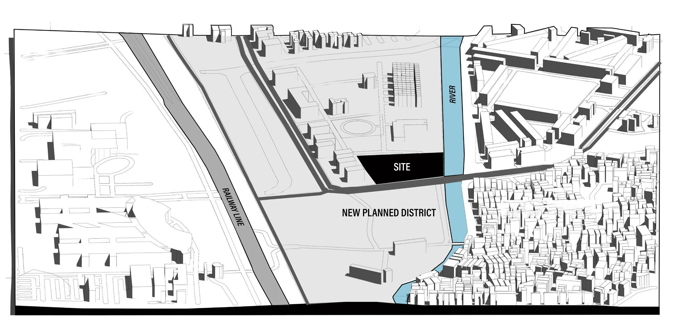
Newly planned district Residential district Commercial district VIEW FROM SITE ENTRY 2
Administration district
FLUIDITY
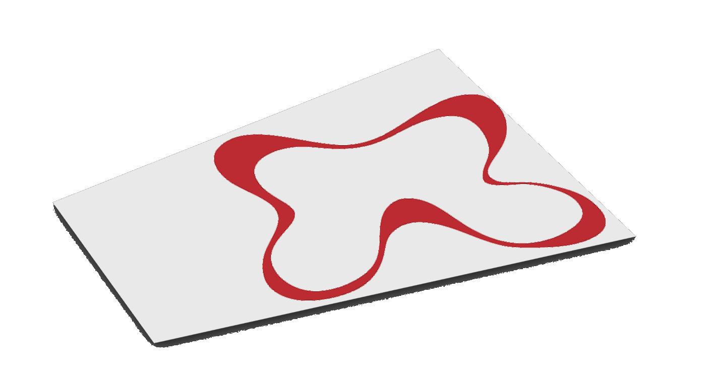
Fluidity is an expression of art, creativity and imagination. Deriving a fluid form as an icon for planning.
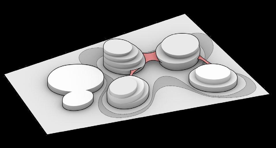
BRIDGING
Connecting building blocks through bridges
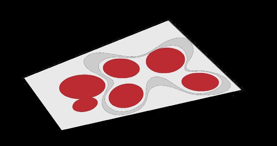
BUILDING FOOTPRINT
Setting building block footprints in tune with the fluid site plan.
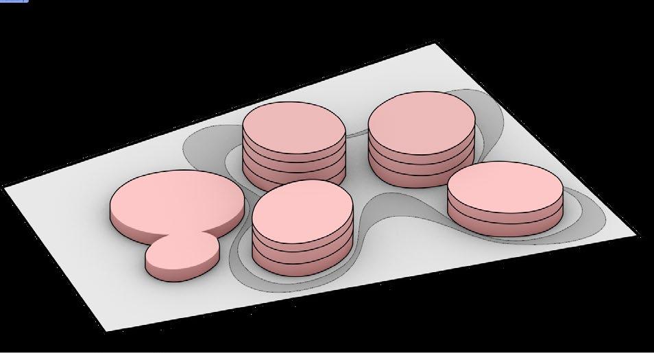
BUILDING BLOCKS
Assembling the building blocks as per brief requirements, planning and connectivity.
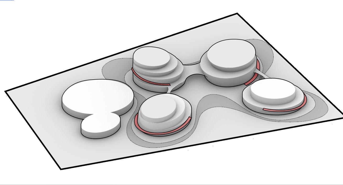
‘RAMPS’ AS VERTICAL CONNECTIONS
Establishing vertical connection between each level through ramps instead of lifts to achieve sustainability in vertical transport.
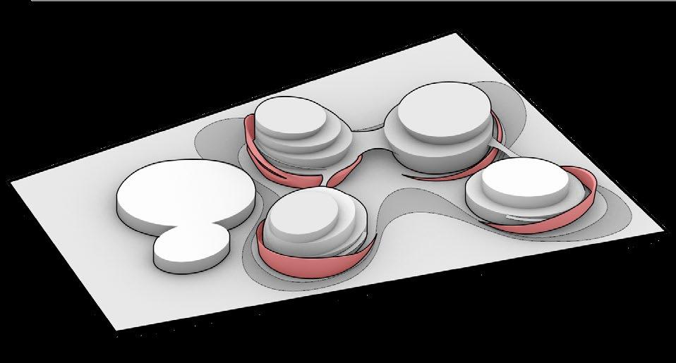
ENCLOSURES AND SUPPORTS
Providing supports to ramps and giving a shield from weather through a wall enclosure around it.
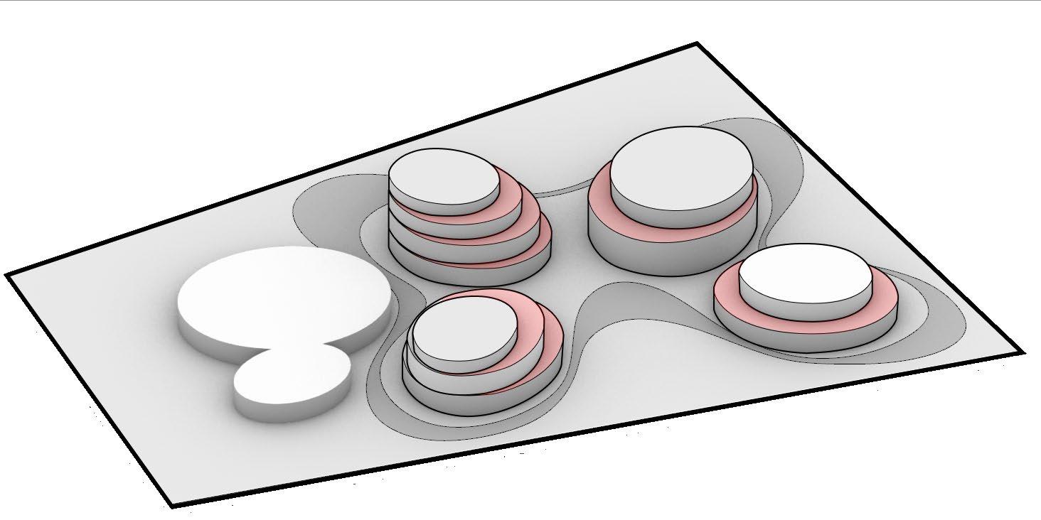
TERRACES ON EACH FLOOR
Making space for creating terraces on each floor to enable visual and physical connection with sky and nature.
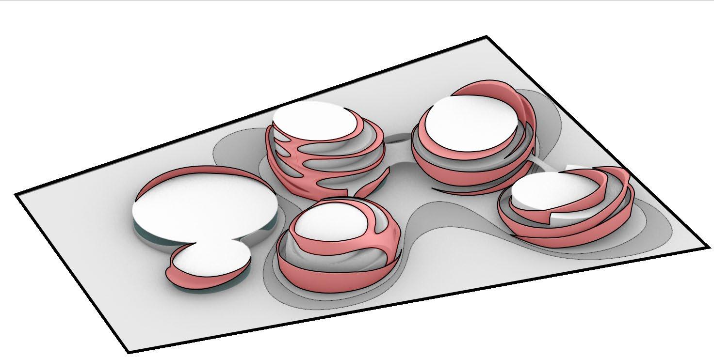
THE ‘FORM’
Dynamic and aesthetic skin for the building to match the central idea of an ARTISTIC art institute
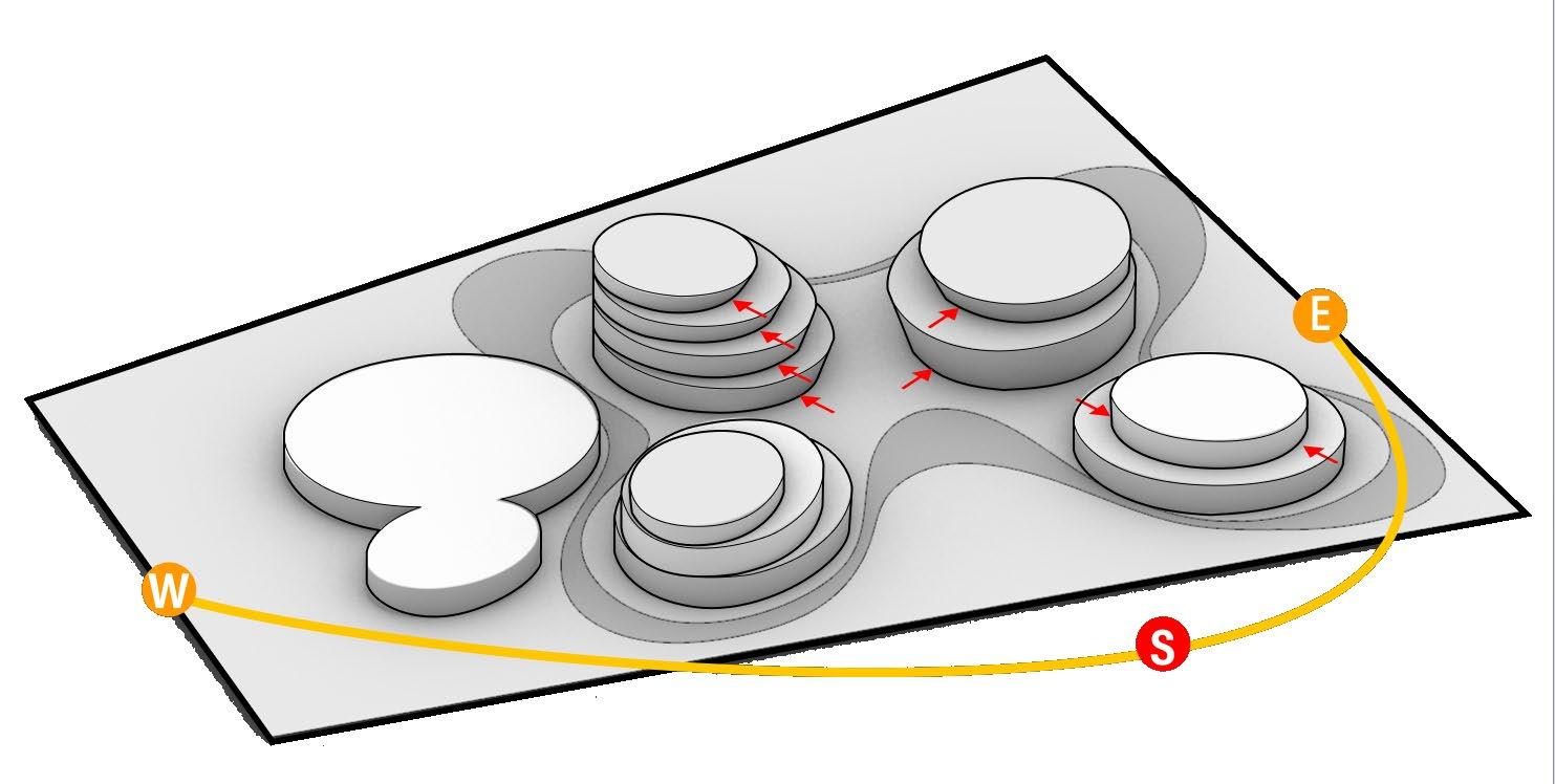
TILTED FACE
To mitigate intense heat, the approach involves inclining the facade walls facing south on each floor by pushing the lower edge of the blocks inwards.
THE LANDSCAPE
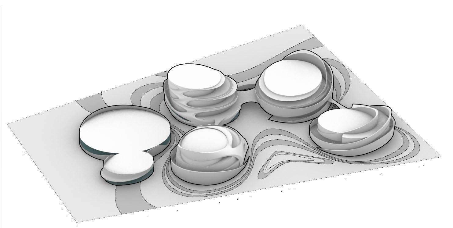
Fluid pattern landscape enveloping the building to complement the fluid geometry
6 2 7
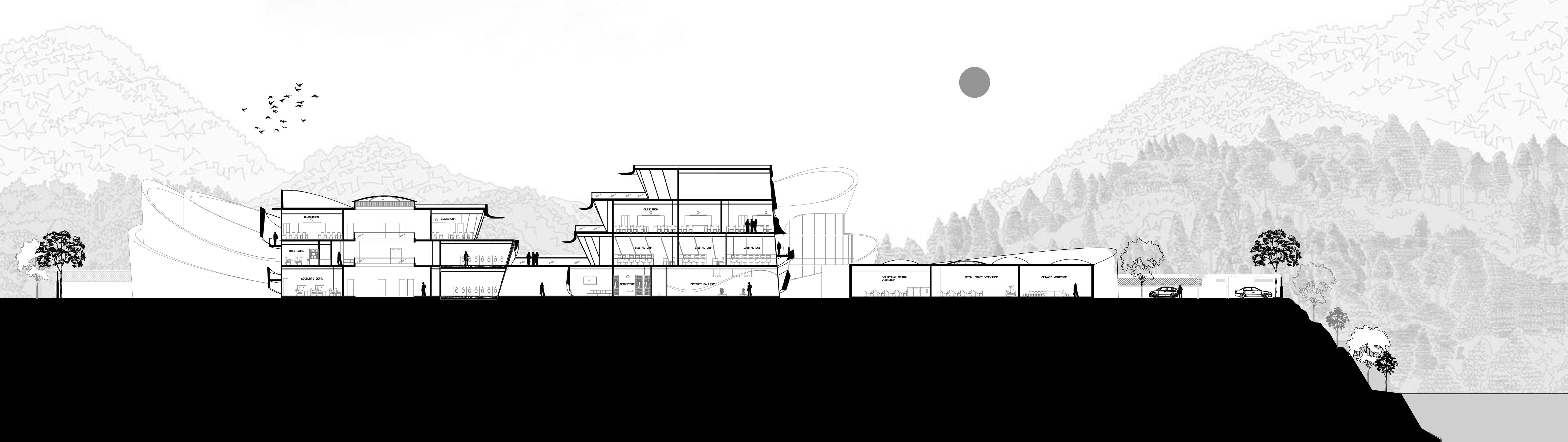
5 SITE SECTION 3
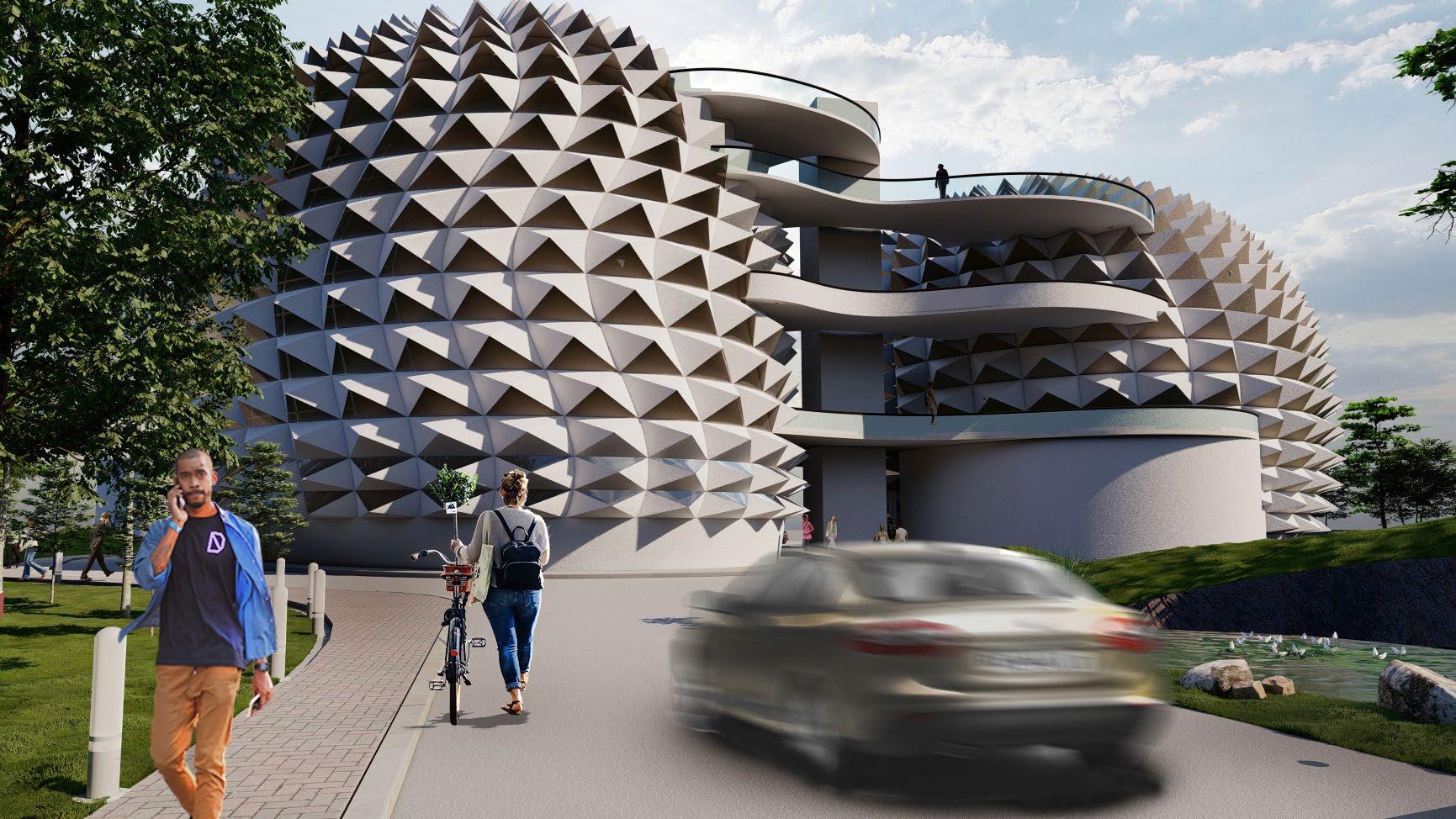
• To avoid direct penetration of heat in the rooms, the south facing facades are inclined and roofed.
• Learning becomes boring when just enclosed in a classroom, hence in order to avoid that, spillout spaces (terraces) on each floor and with access to all classes is planned.

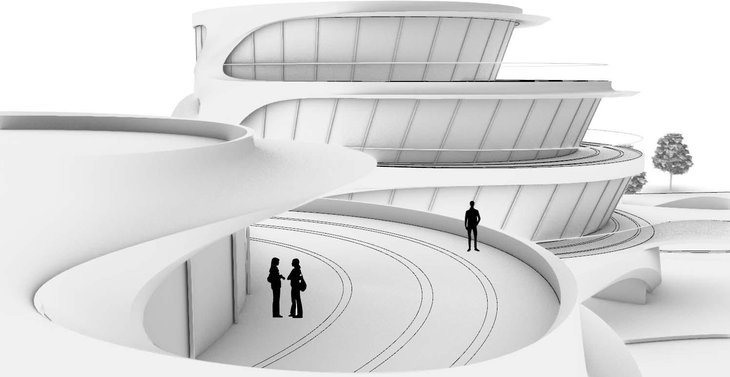
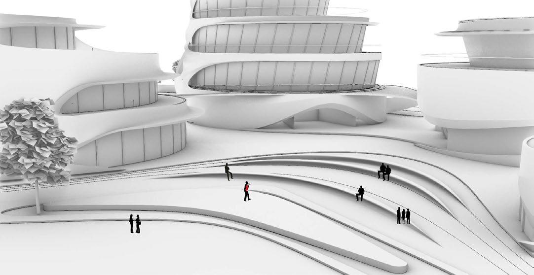
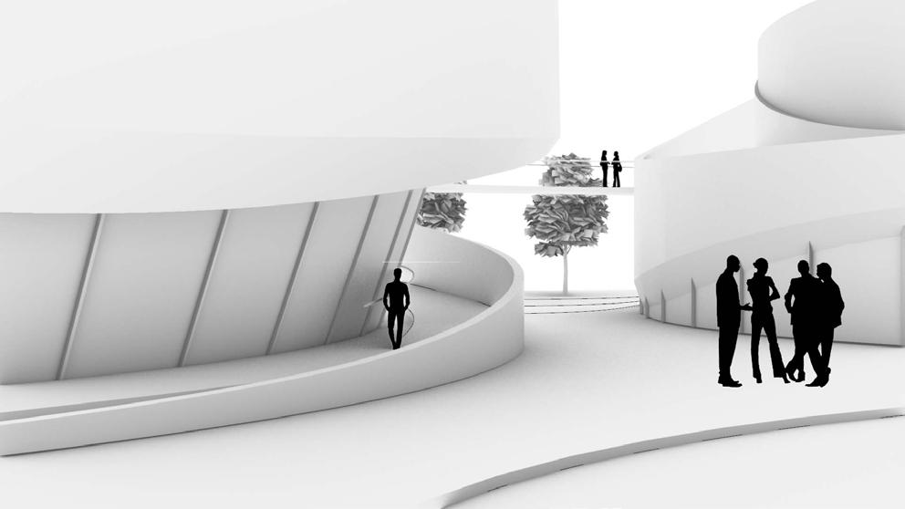
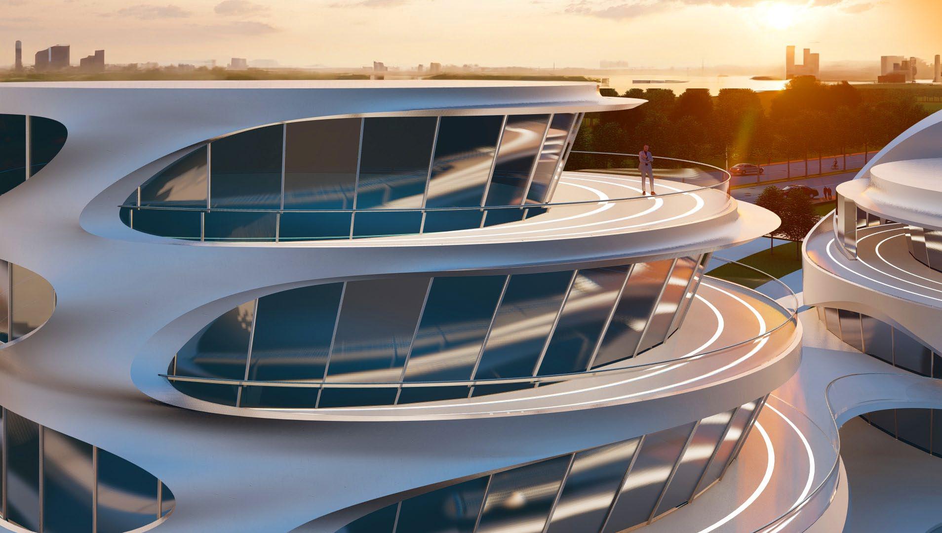
 View of vibrant interactive terrace spaces created on each floor
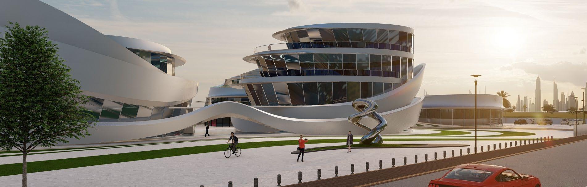
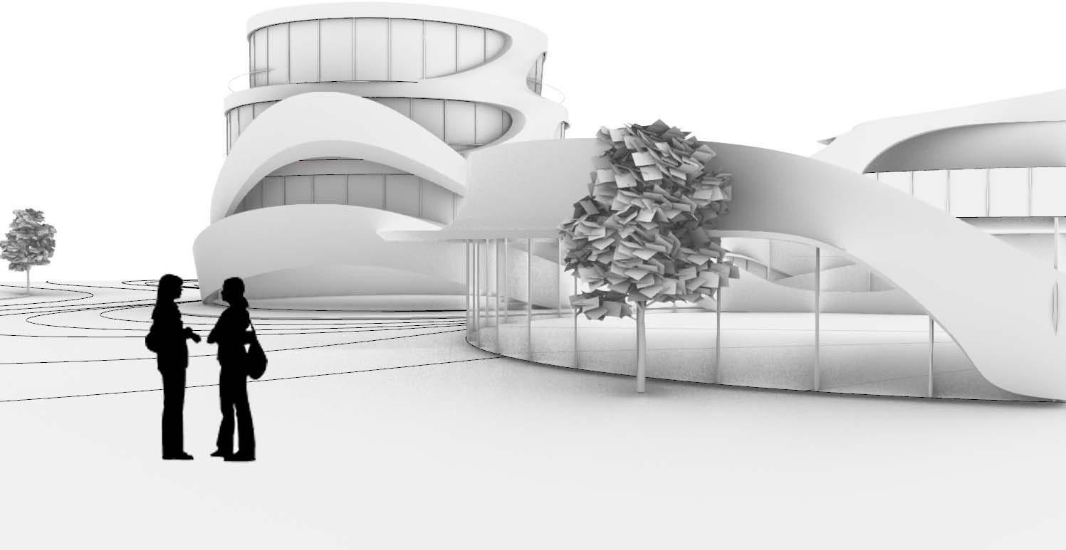
View of the site from parking space
Amphitheatre in a central recreational ground
View of vibrant interactive terrace spaces created on each floor
View of the site from parking space
Amphitheatre in a central recreational ground
PASSIVE DESIGN STRATEGIES
View of ramps and bridges connecting the structure
4
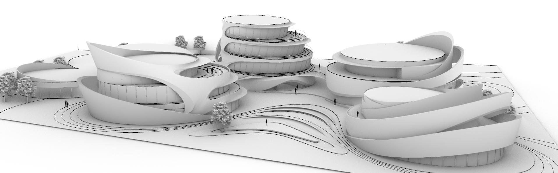
AERIAL VIEW OF 3D MODEL
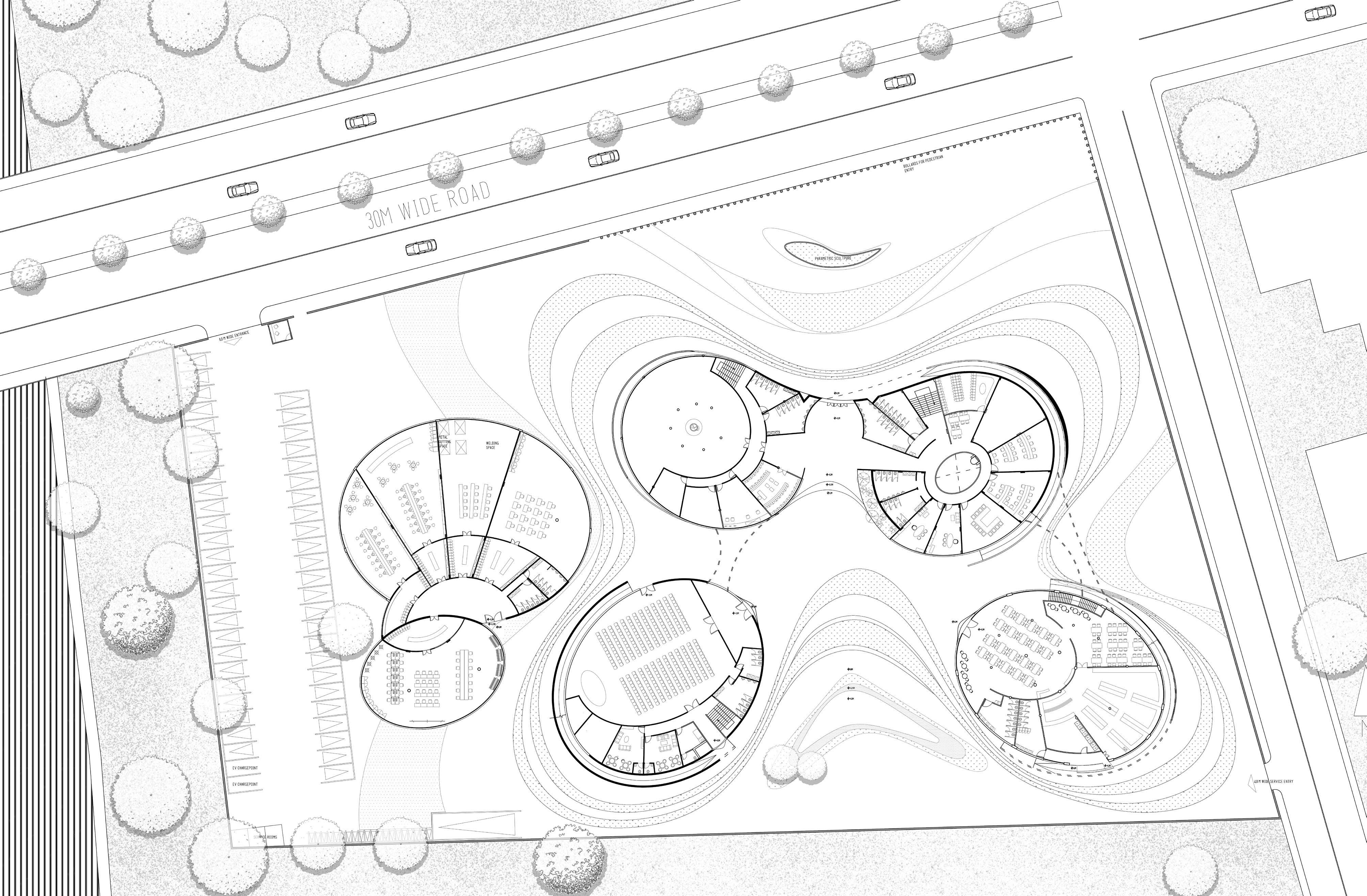
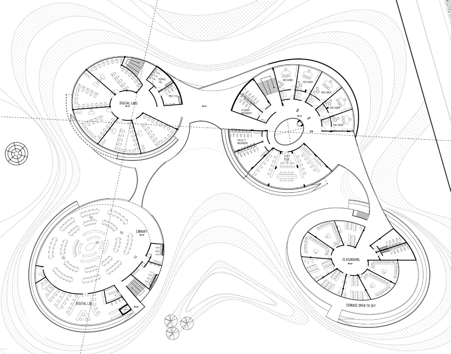
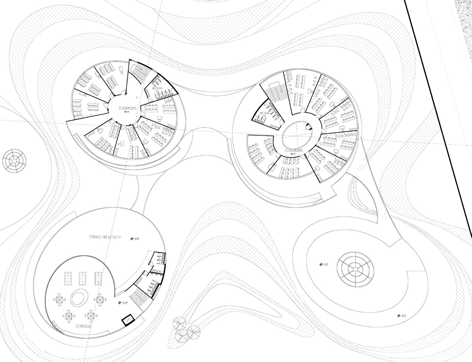
SITE PLAN / GROUND FLOOR SECOND FLOOR PLAN FIRST FLOOR PLAN 16 1 2 3 2 6 5 5 5 4 4 4 4 4 4 4 4 4 4 4 4 5 5 7 5 13 10 12 11 6 8 9 14 6 16 16 17 17 17 17 17 16 16 18 15 15 3 3 01 - Entrance & reception 02 - Product gallery and store 03 - Service rooms 04 - Restrooms 05 - Office and administration 06 - Storage room 07 - Courtyard / Atrium 08 - Amphitheatre stage 09 - Amphitheatre seating 10 - Canteen common dining area 11 - Staff cafeteria 12 - Central kitchen 13 - Multi-purpose hall 14 - Pantry (for hall) 15 - Boy’s room & girl’s room 16 - Art workshops 17 - Tools and lockers room 18 - Common waiting area 5
The Fashion Hub
Location: Lower Parel, Mumbai, India
Type : Semester 5 studio // Individual
Site area: 9,602 sq.m
Duration: Dec’21 - Apr’22
6
About Approach
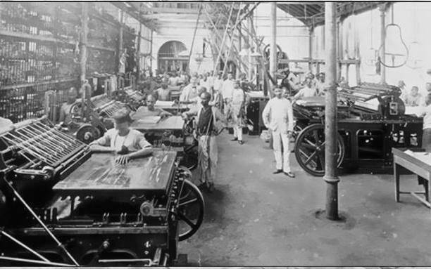
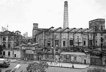
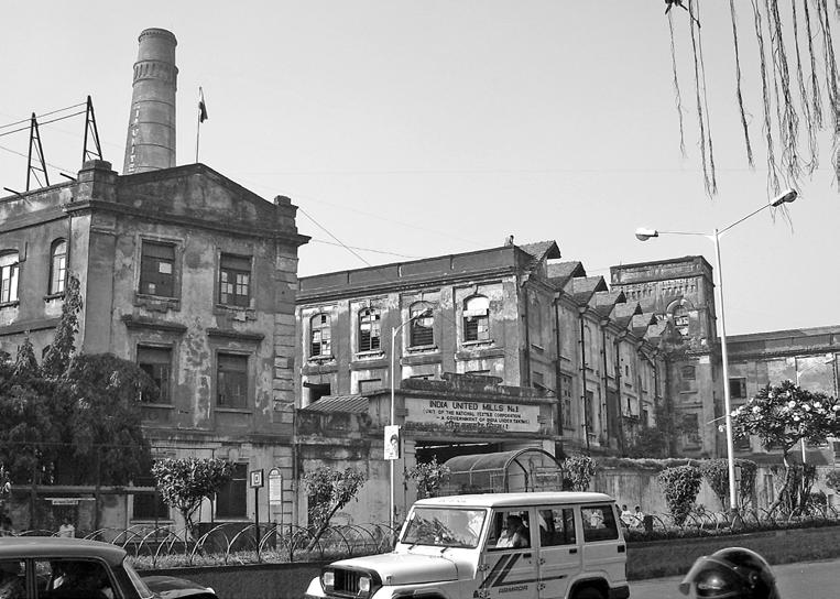
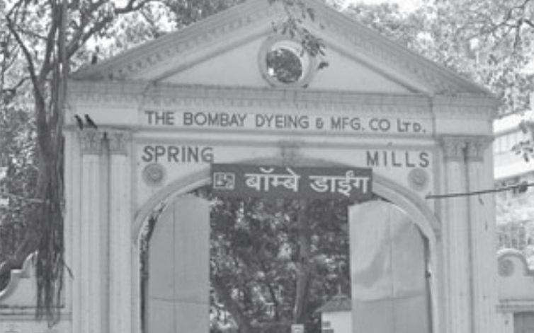
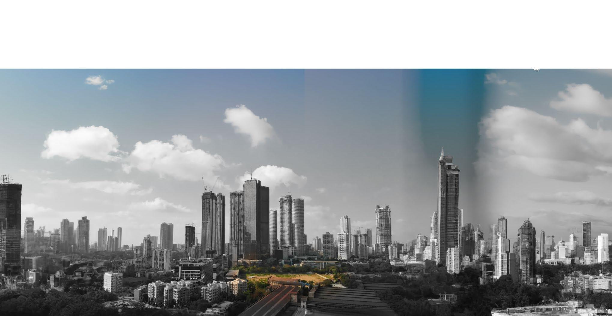
Lower Parel in Mumbai is a former textile and fashion hub with a rich history and legacy. However, many of the textile mills in the area have become redundant in recent years. This project aims to revive the area’s character as a center of textile and fashion by creating a fashion hub.


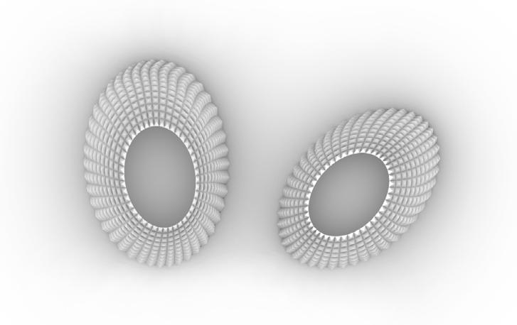

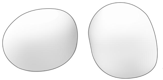
Deriving a building mass after organising all spatial requirement
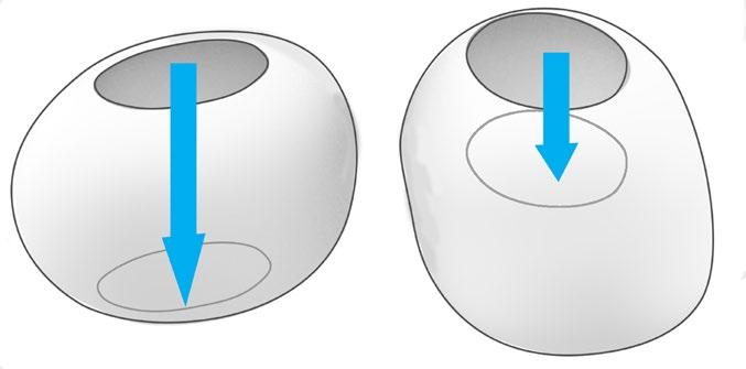
Making atriums/courtyards for multilevel visual connectivity and air ventilation
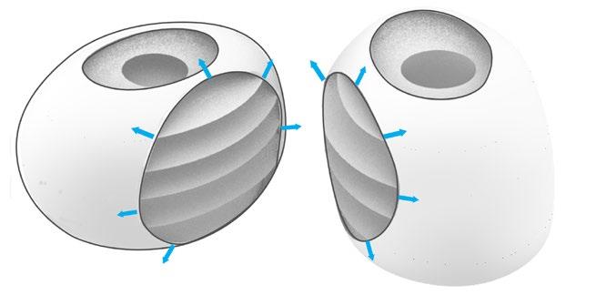
Opening the facade (fenestration) on the north for north-light and deriving floor plates
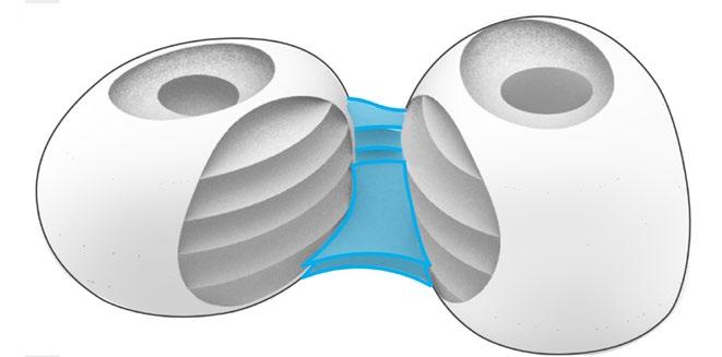
Bridging the two buildings by a semi-open terrace and corridors open to air.
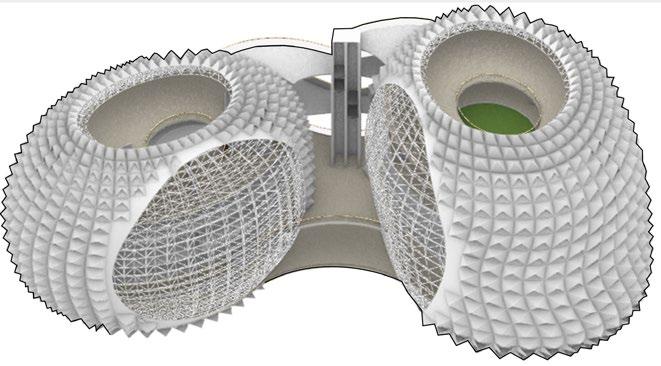
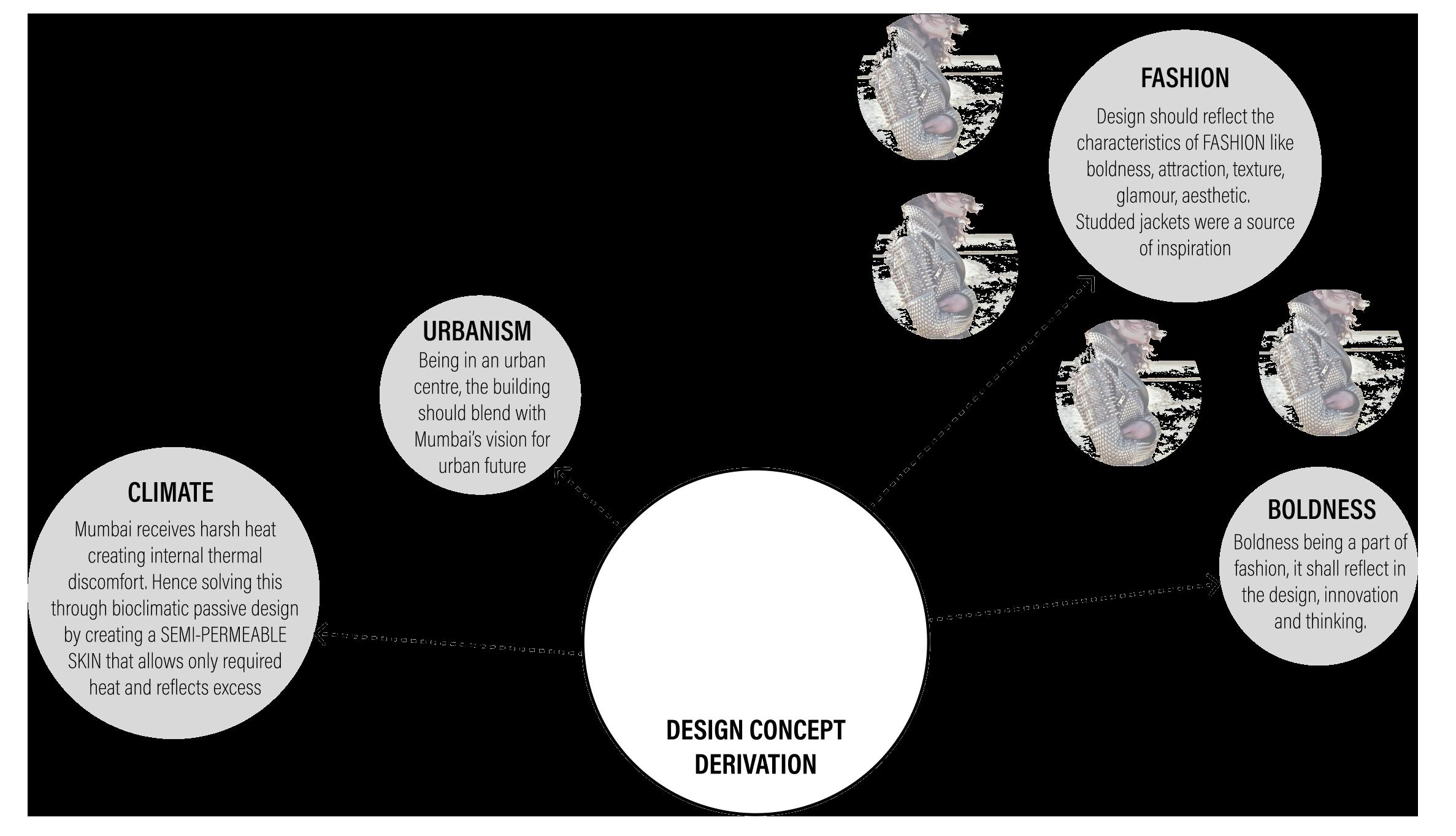
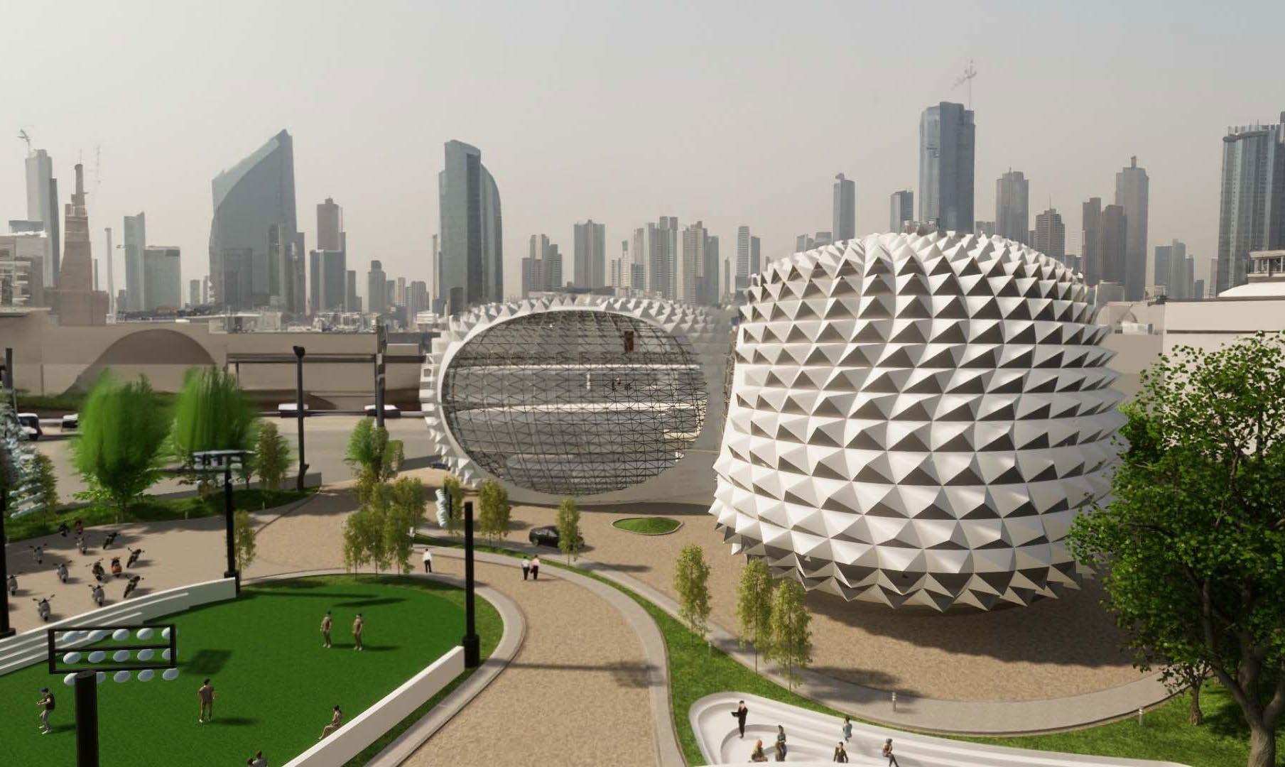
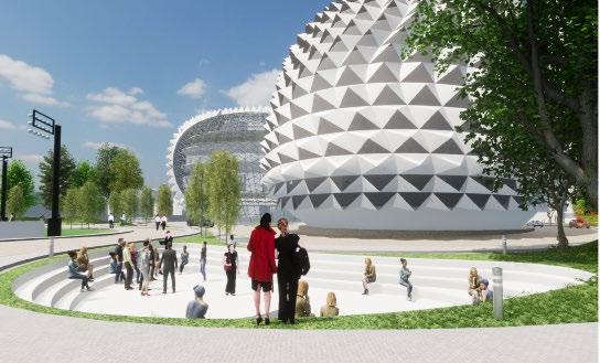
Treating the building envelope with bioclimatic pattern forming a semipermeable thermal skin
Site image
7
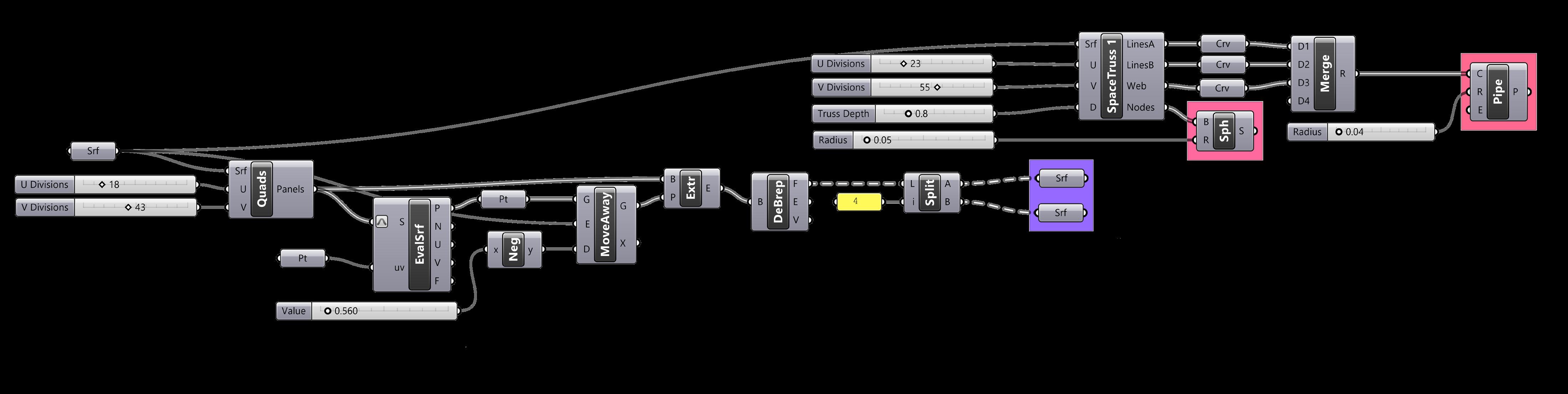
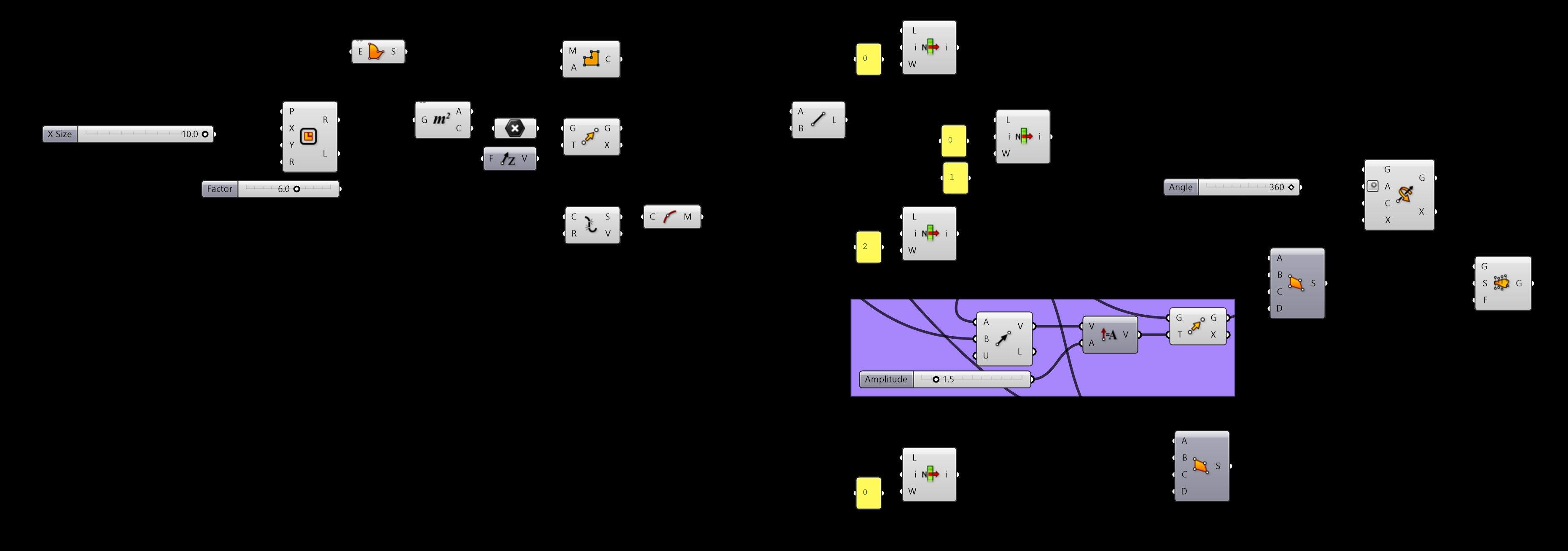
The following grasshopper script indicates the process employed in order to achieve the building facade/skin along with the supporting space frame as shown in the images.
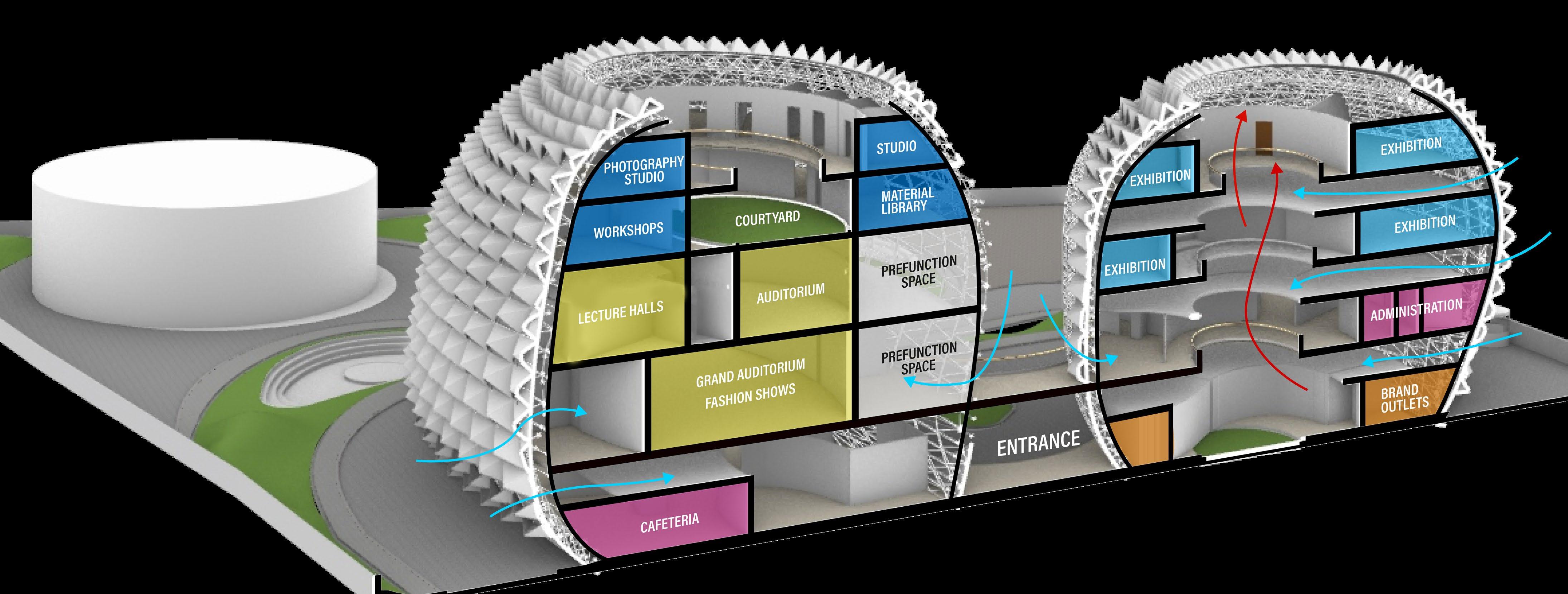
BUILDING SKIN SPACE FRAME Entertainment & Assembly Administration spaces Studios & workshops Exhibition & museum spaces Commercial spaces
8
A bioclimatic strategy designed to beat Mumbai’s heat: a semi-permeable building skin with angled, customized openings. These strategic fenestrations filter sunlight, ensuring a pleasant and thermally comfortable interior by studying angles and exposure, offering a nuanced solution to the harsh climate.

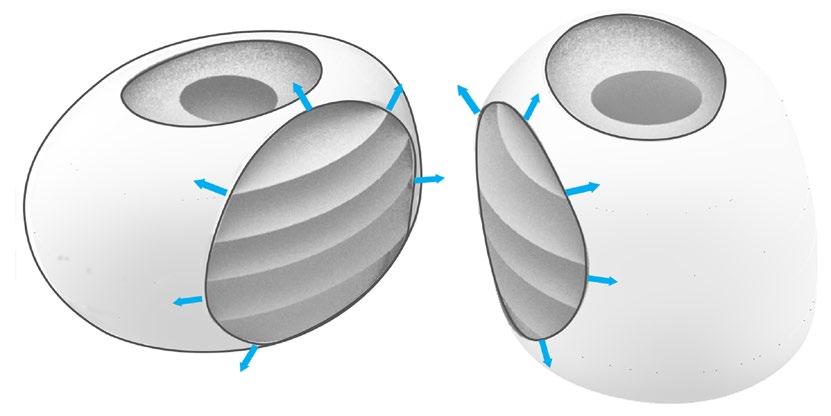

Large openings towards the North (for comfortable and pleasant light)
Passages and toilet planned towards the south (direction receiving harsh sunlight)
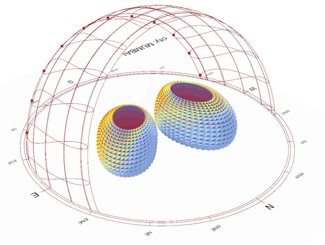
SUN HOURS ANALYSIS
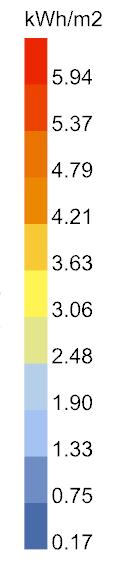
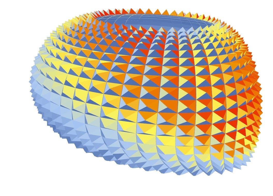
The analysis reveals that the structure receives direct heat majorly on the south facade, with other parts receiving diffused and comfortable sunlight.

RADIATION ANALYSIS
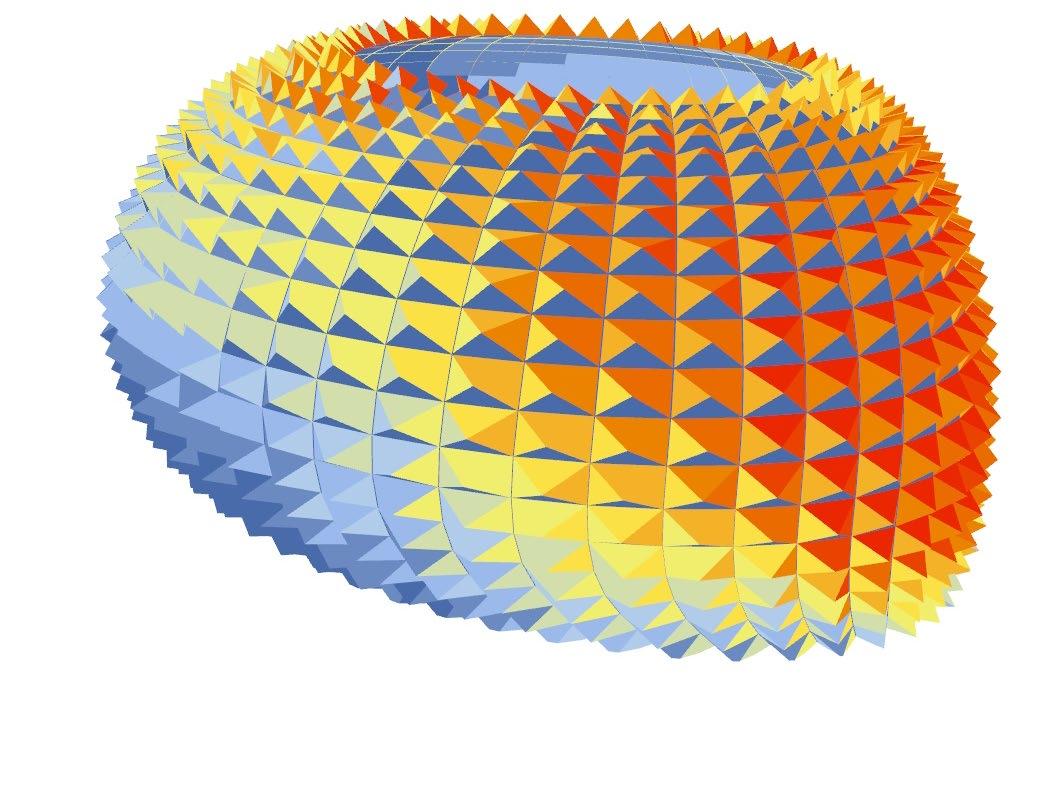
The sun radiation analysis shows how the bioclimatic strategy for building skin is protecting the openings from receiving harsh sunlight
PHASE 2
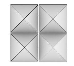
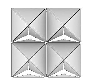
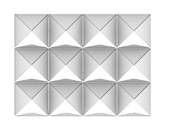
In times of intense heat, the openings can be automatically closed to ensure comfort.
PHASE 1
Open fenestrations allowing view and light
KINETIC FACADE SCRIPT
FACADE SKIN - CONCEPT AND ANALYSIS
9
SUN-PATH
Laying of pile foundation for strong super-structure
Erection of shear walls and RCC columns as primary vertical load bearers
Using advanced slab types: flat slab, waffle slab for longer column free span
Covering the structure skeleton with a space-frame as per desired shape 12:00 NOON Harsh sunlight blocked by the facade
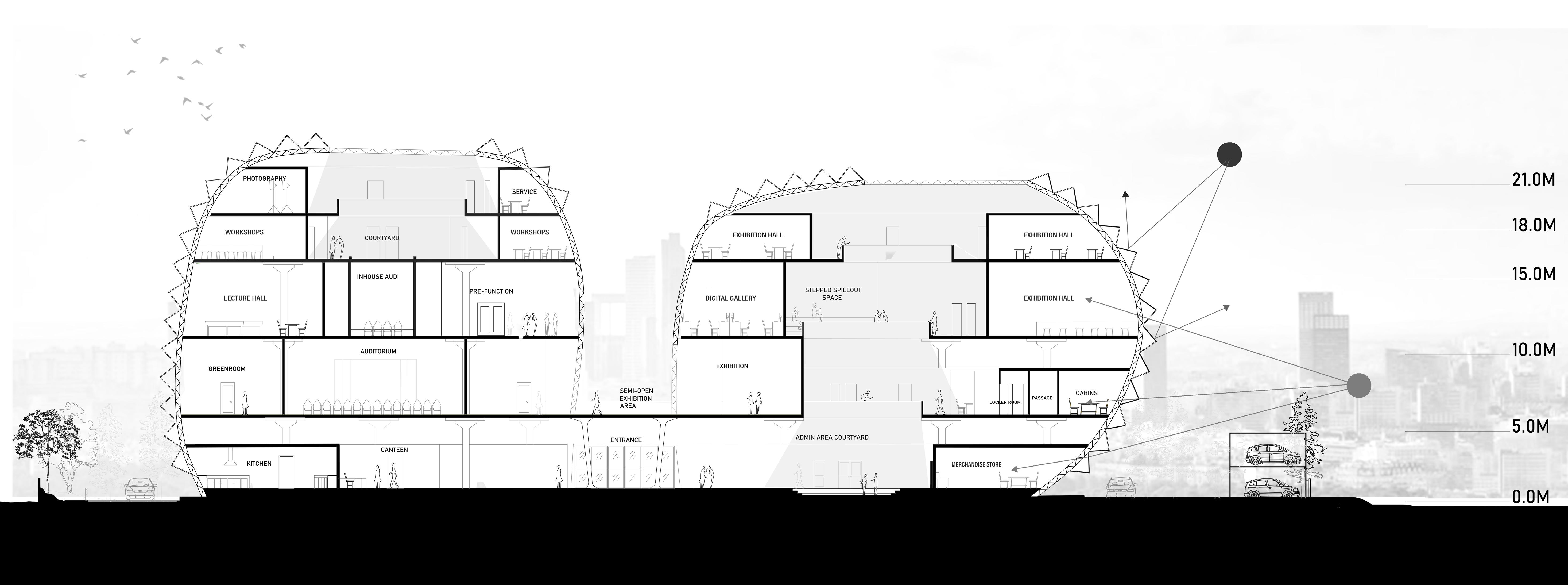
Customized openings according to sun-path 8:00 MORNING Pleasant sunlight allowed to penetrate
GFRC PANEL FRAME GLASS SPACE FRAME INTERIOR PANEL
GFRC Panels Frame Glass glazing Space frame Interior panels
ILLUSTRATIVE SECTION 10
CONSTRUCTION CONCEPT DIGRAM
BLOW-UP SECTION
The Floating Pavilion
Location: River Drava, Slovenia
Type: Competiton // Individual
Duration: April 2022
11
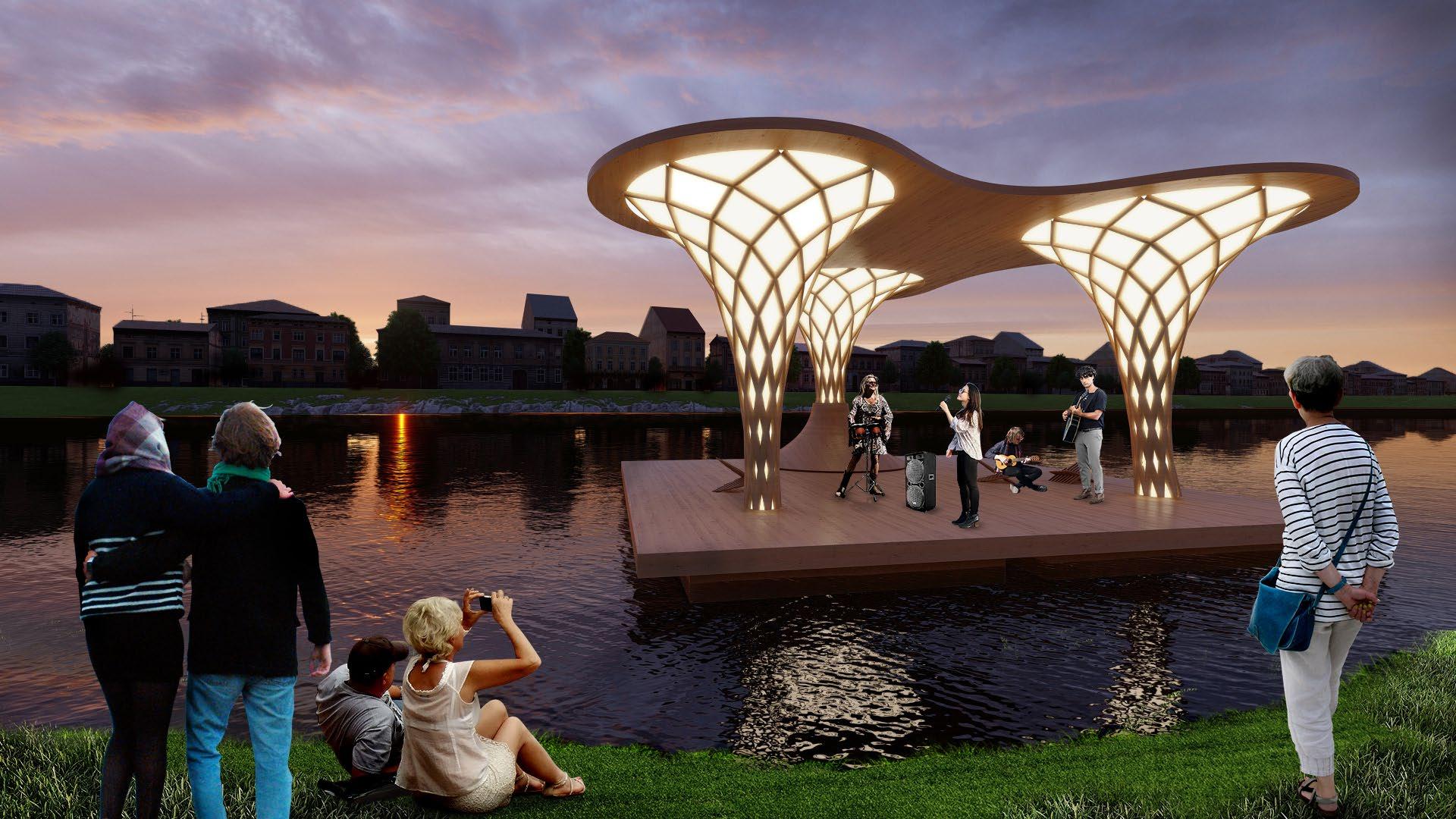
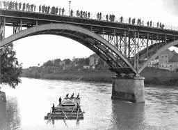
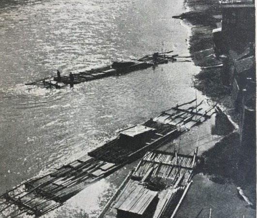
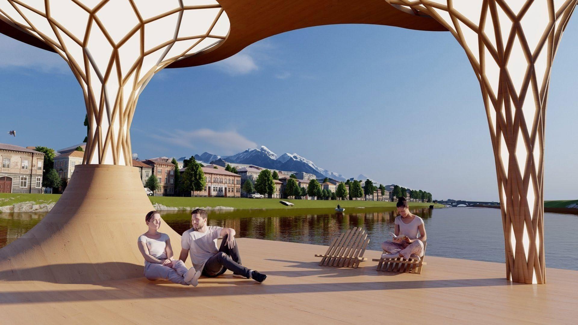
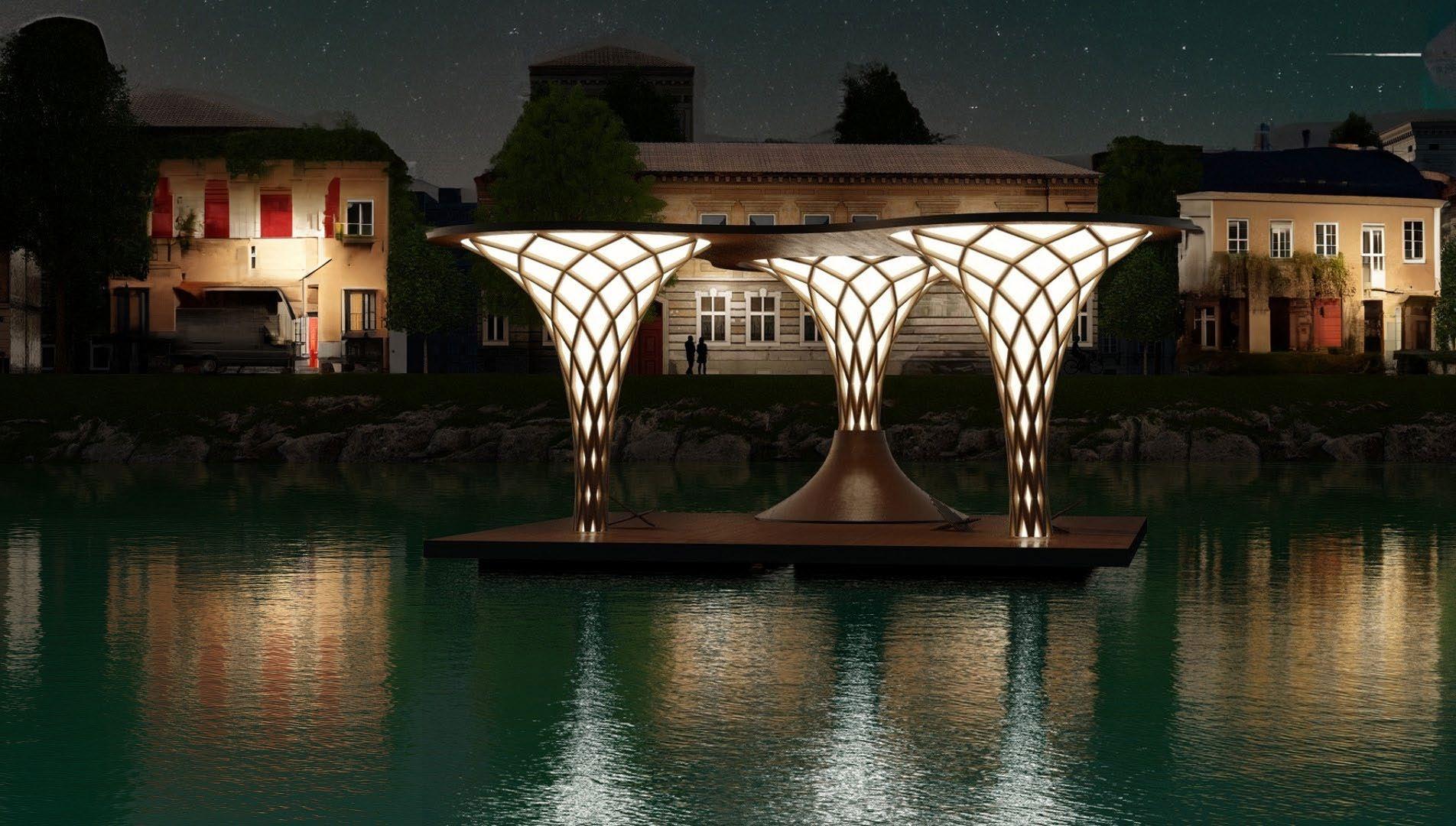
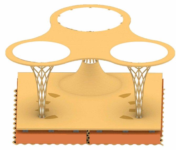
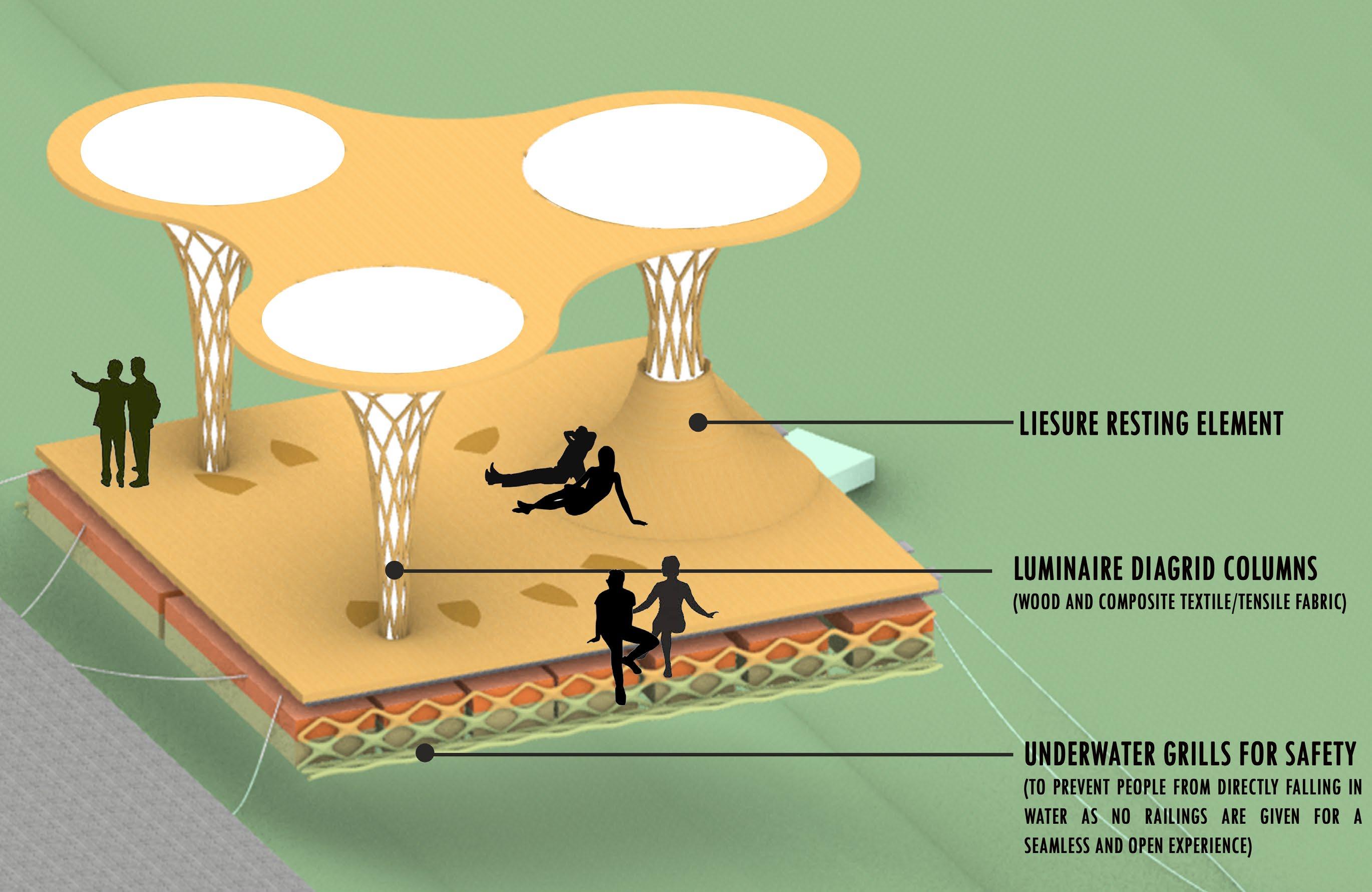
The project’s objective is to rejuvenate the city of Maribor in Slovenia, renowned for its rich heritage of raft transportation on the Drava River, by constructing a floating pavilion. This pavilion should be designed to be easily relocated and adapted to a variety of scales and purposes.
Brief requirements:

Wood to be used as primary material
Pavillion size given - 8m x 8m

Adaptive to multiple purposes and scale of use
Objectives
• Simple and minimal design for convenience of users
• To design adaptable furniture for versatile purposes
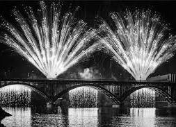
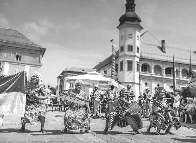
• To create an attractive aesthetic appearance especially for its relevance during Lent festival.
Position 1
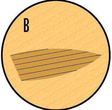
Seats collapsed on the floor
Position 2
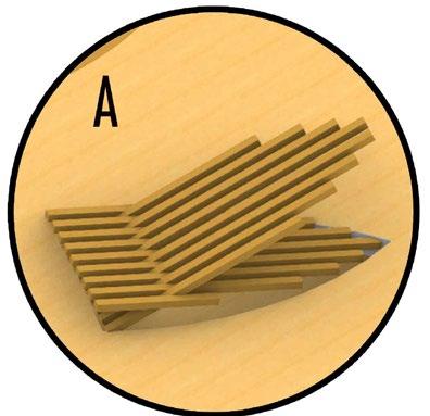
Seats cropped up when required

 Lent Festival
Maribor’s raft legacy
Lent Festival
Maribor’s raft legacy
About
12
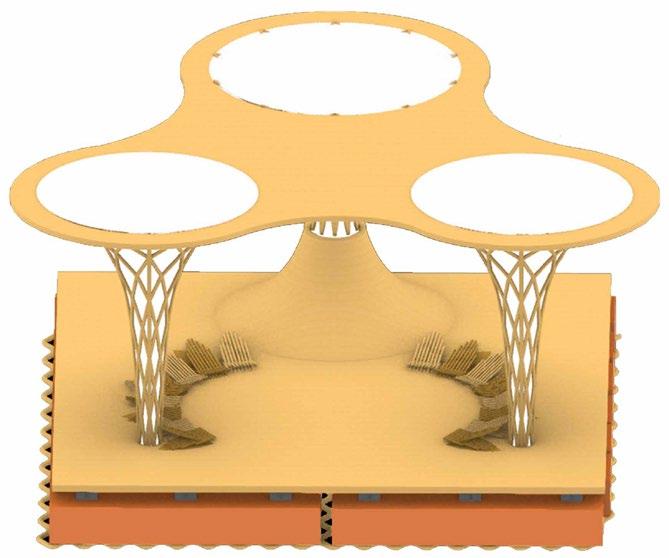
On-board assemblies
All seats cropped up for on-board assemblies like seminars, talk shows, wine tasting, etc.
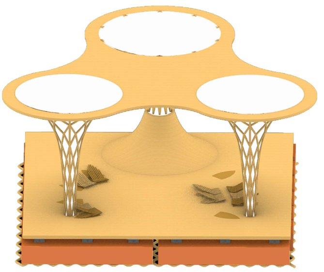
Regular use
Seats can be pulled up as required for public use like leisure, relaxation, etc.
Performances
All seats collapsed to clear space for performances to be viewed by people from banks
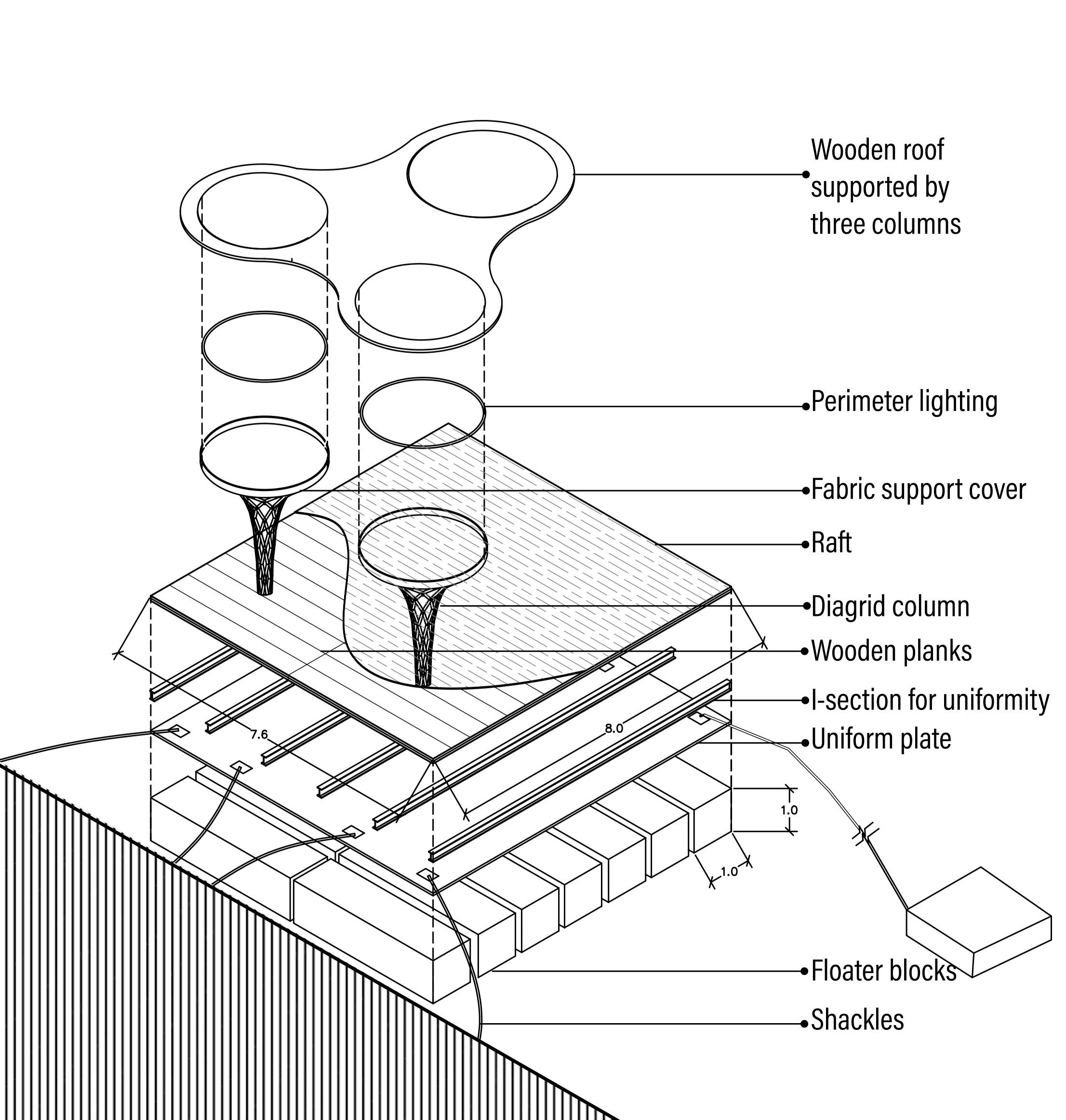
AXONOMETRIC EXPLODED DIAGRAM
DYNAMIC SEATING CONCEPT
13
The Martian Agrohabitat
Location: Candor Chisma site, Mars
Type: Winterschool design studio // Group of 3
Affiliation: AAKA Space studio, Canada + NASA India
Duration: 2 months // Feb-Mar’22
Contribution: Concept design, Research, Modelling
14
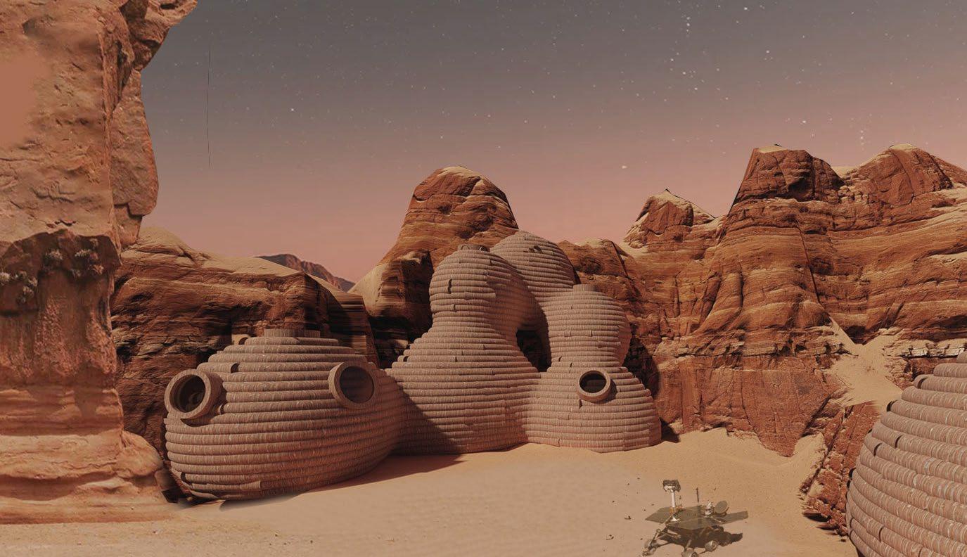
The ‘Martian Agrohabitat’ is a Martian human space settlement coupled with the functions of Research. Any prospective space settlement would first need to answer the question of ‘How to grow a viable source of food’ in a drastically different enviornment. The ‘agrohabitat’ would serve as the stepping stone and primarily focus on permutation, hybridization and experimenation of vegetation on Mars. The habitat is designed for a crew size of five humans.
Approach
The zoning has been developed to create a closely earth like environment for cosonauts. A vertical zoning over a horizontal is preferred for better volumetric efficiency. Vertical circulation will not be a problem due to low gravity on Mars.
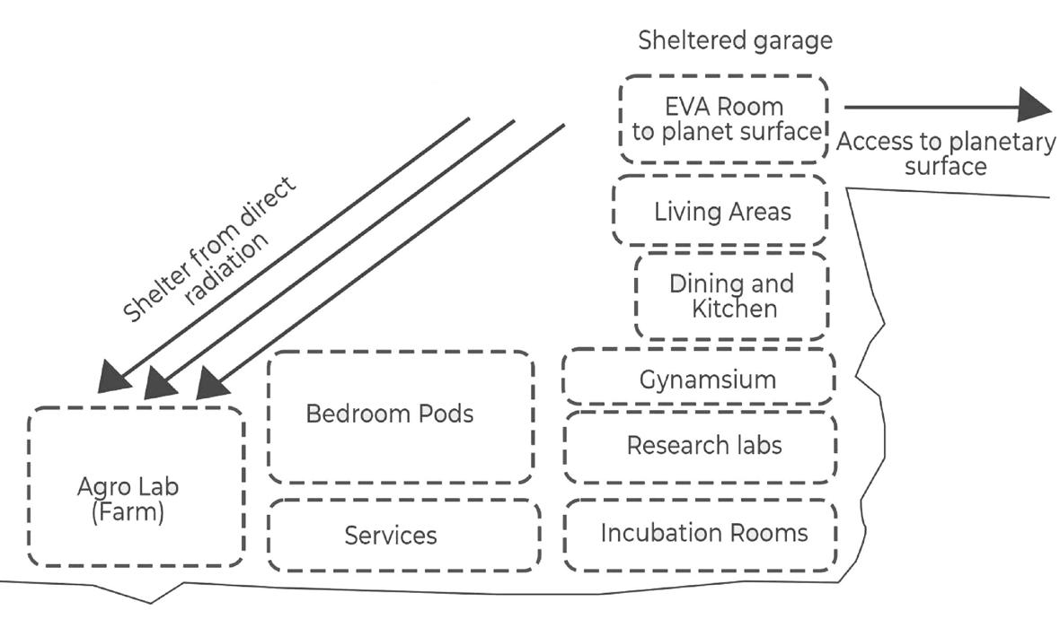
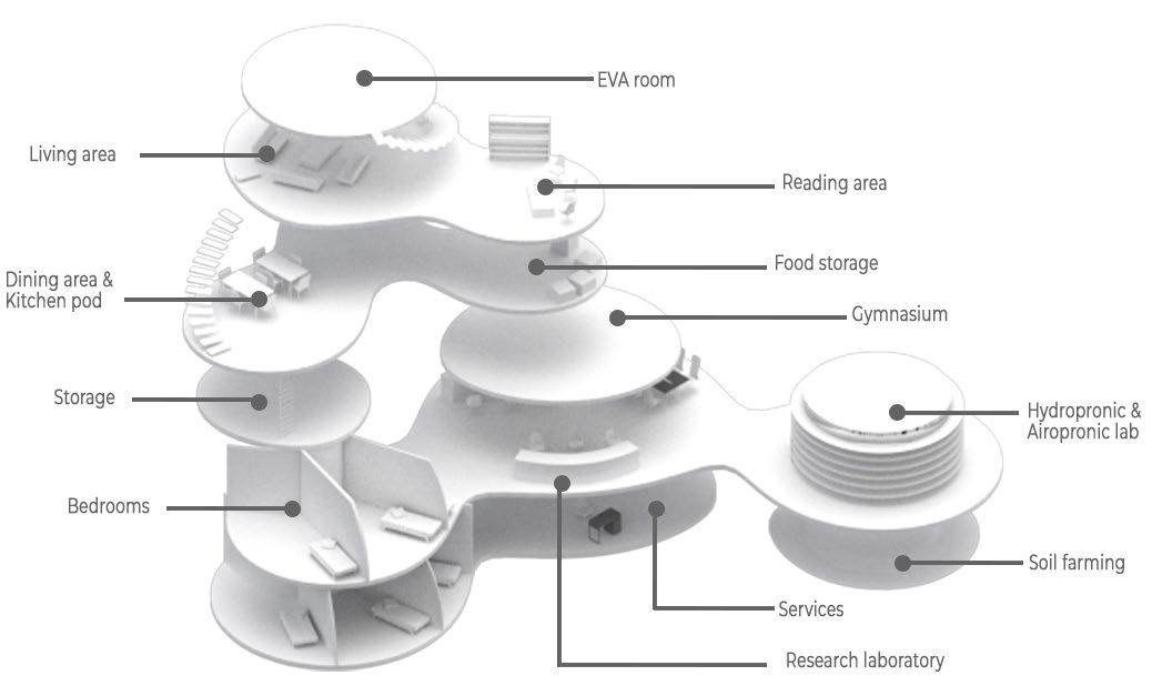
The proposed structure is a free standing catenary lean-on type of a structure built in the sheltered environment of crater, as a host, for better radiation protection
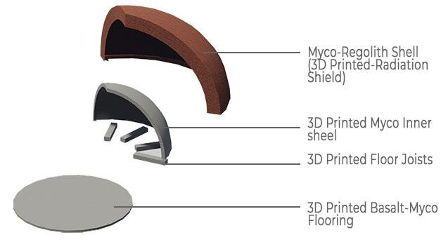
The double shell structure has been adopted for easy pressurization and enhanced radiation protection. The outer shell is made up of fibres created by mycelia and acts as a reinforcement addition to Martian regolith
Materials used:
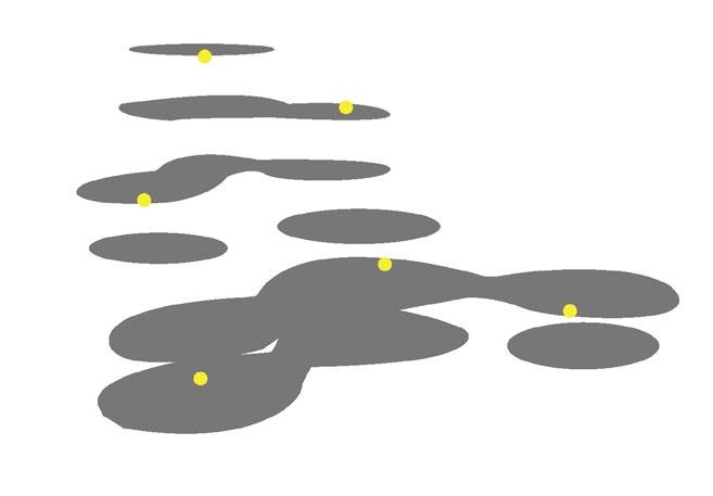
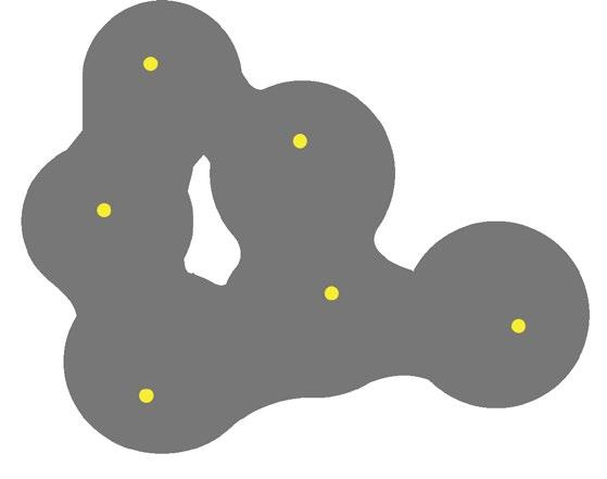
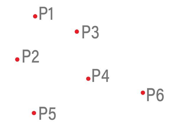
CO-ORDINATE POINTS
Source points defining levels and functions
Creation of metaballic planes defining floor plates
Metaballs defined as per volumetric calculation based on anthropometry in Mars
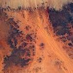
Regolith: Abundantly available in Mars, and provides radiation shield
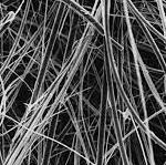
Lightweight, durable and easy to produce in-situ
About
Martian
Myco Fribre:
FLOOR DERIVATION
METABALLS
15
Affordable housing
Location: Pune, India
Type: Semester 7 studio// Individual
Site area: 23,000 sq.m
Duration: Jun’22 - Oct’22
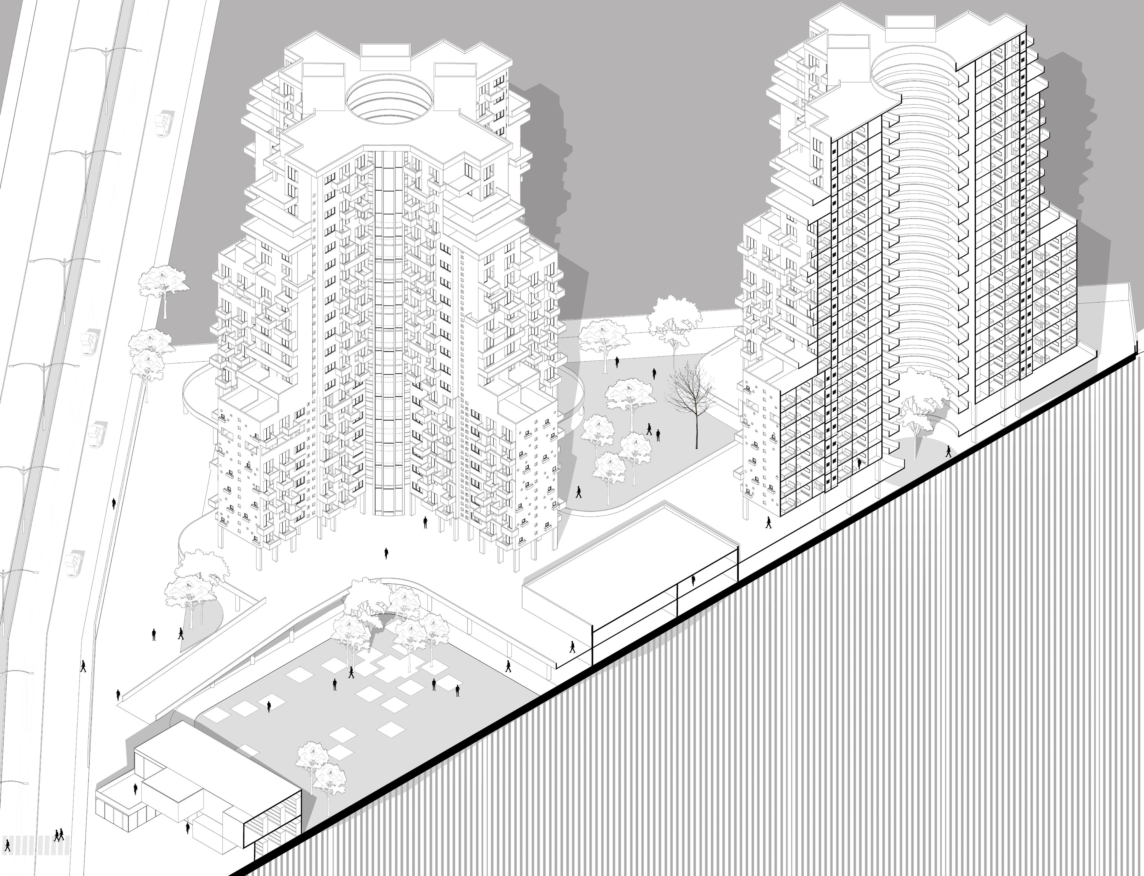
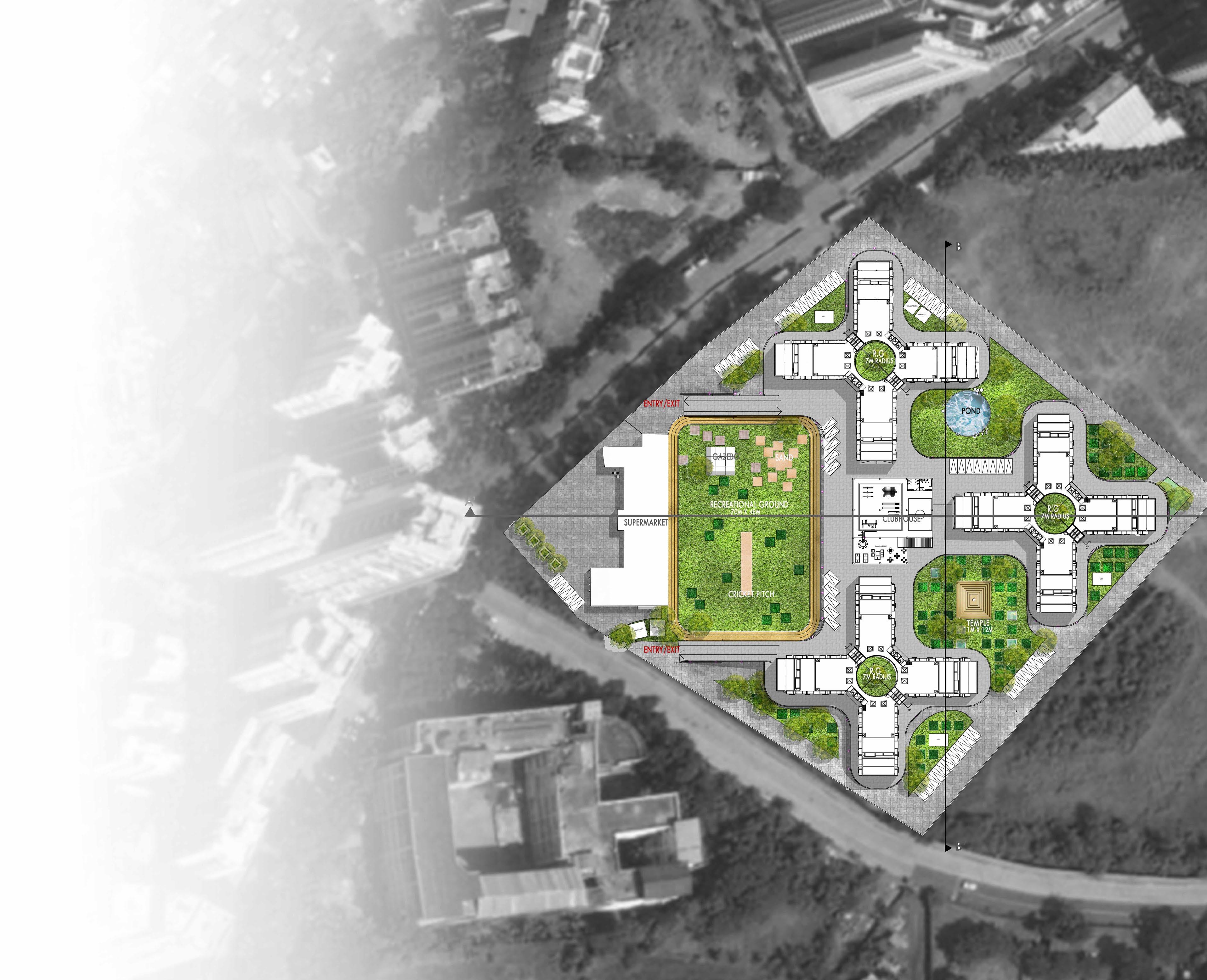
Pune, often dubbed the ‘Silicon Valley of India,’ is among the country’s most densely populated cities. The city’s flourishing IT sector has spurred a rising demand for affordable housing, particularly among middle-class families. The project aims at accommodating residents from different economic stratas forming an urban society.
• Include 1 BHK, 2BHK and 3 BHK housing units catering all economic groups
• Design as per building codes/bye-laws of the city
• Keeping in mind the constructability
About Brief 16
PIXELS - INITIAL IDEA
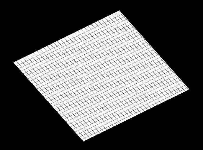
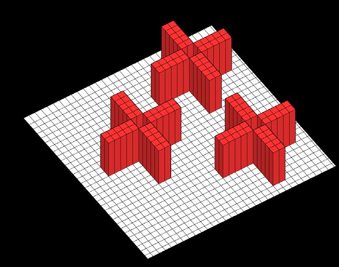
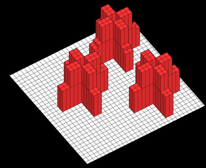
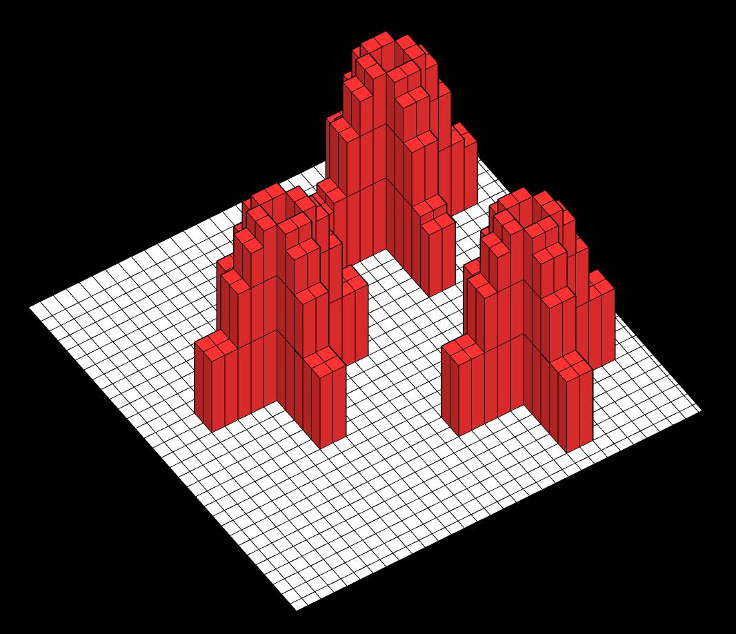
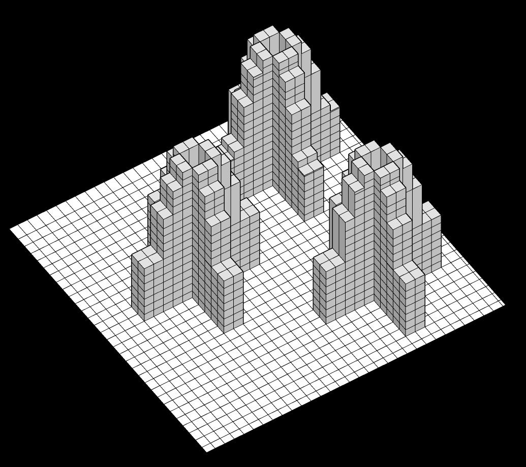
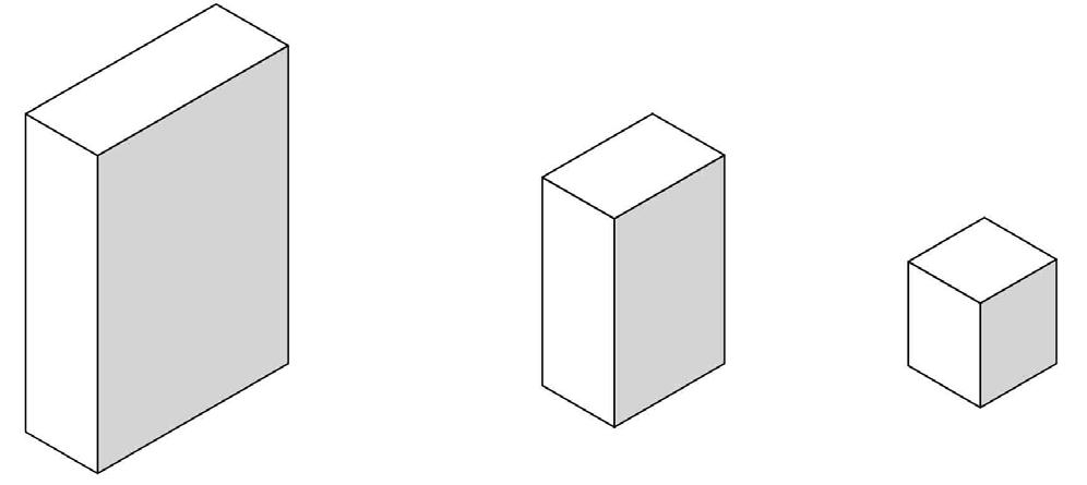
The initial concept revolved around the generation of architectural form through a pixel-based approach inspired by the city’s density. This involved the initial division of the site into pixels and subsequent extrusion of these divisions. The next phase entailed further subdivision of these extrusions into pixels, ultimately influencing the treatment of the building facade.
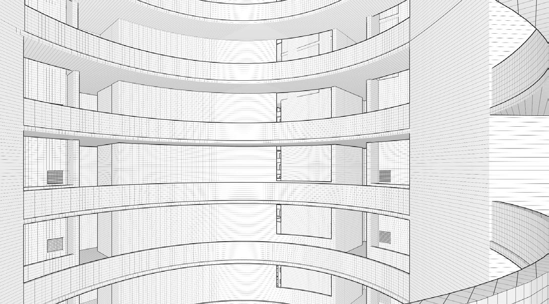
ATRIUM
Designed to build a vibrant social community through multilevel visual connection and interaction
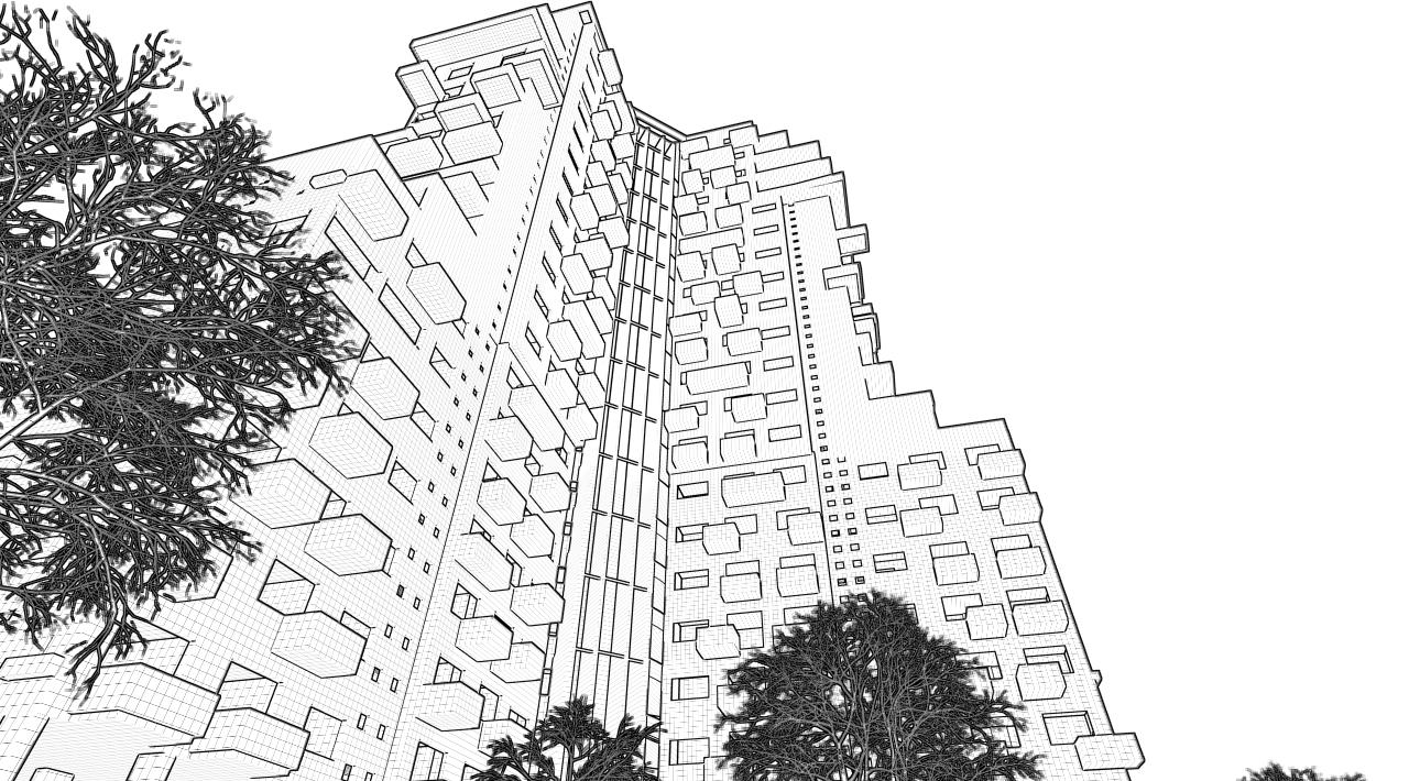
DECONSTRUCTIVIST BALCONIES
Strategically positioned balconies create open, airy spaces above, allowing a direct connection to the sky and avoiding the confined feeling of a slab overhead.
17
RADIAL SYMMETRY
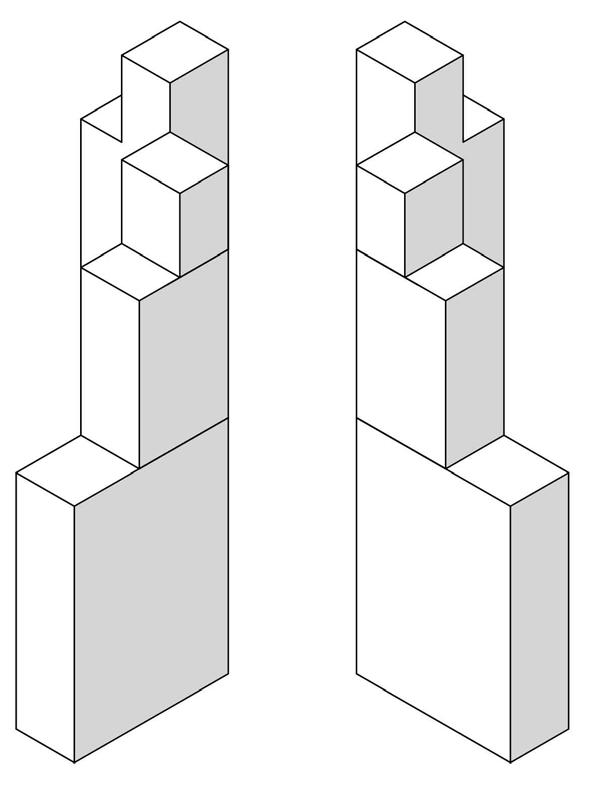
Rotating the typical mass block radially to create four typical wings(blocks) of building
FENESTRATIONS
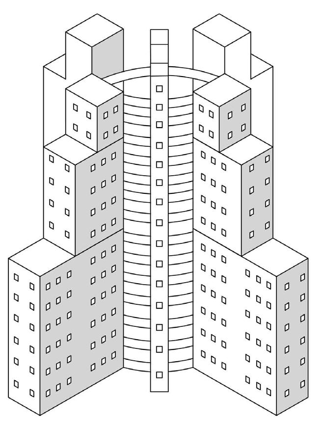
Creating French windows in all rooms for a larger view , while also defining the facade look
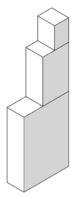
STACKING OF UNITS
The stacking of unit is done one above the other keeping in mind the economic value of each unit
3BHK units at top for best view, followed by 2BHK and 1 BHK below it
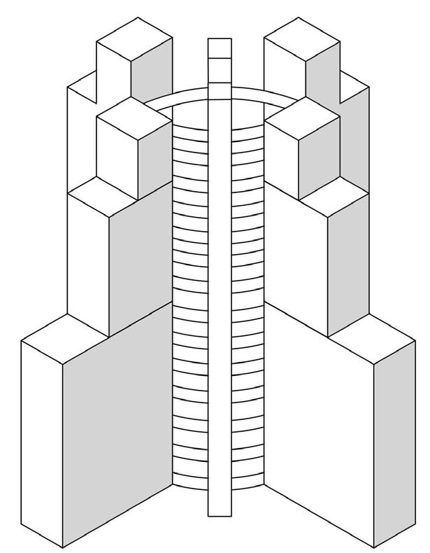
CONNECTING THE WINGS
Creating a circular passage within an atrium connecting all four wings to link people together creating a social interaction within the community
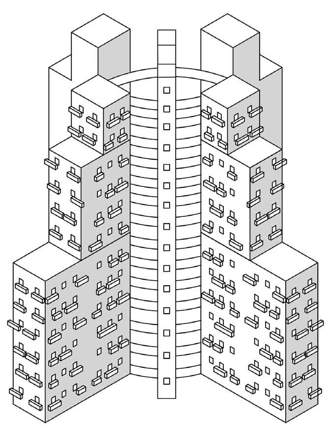
TERRACE FOR EACH ROOM
The concept involves equipping each apartment with a small terrace that is open to the sky or a lofty overhead space. This arrangement will be designed in a random pattern.
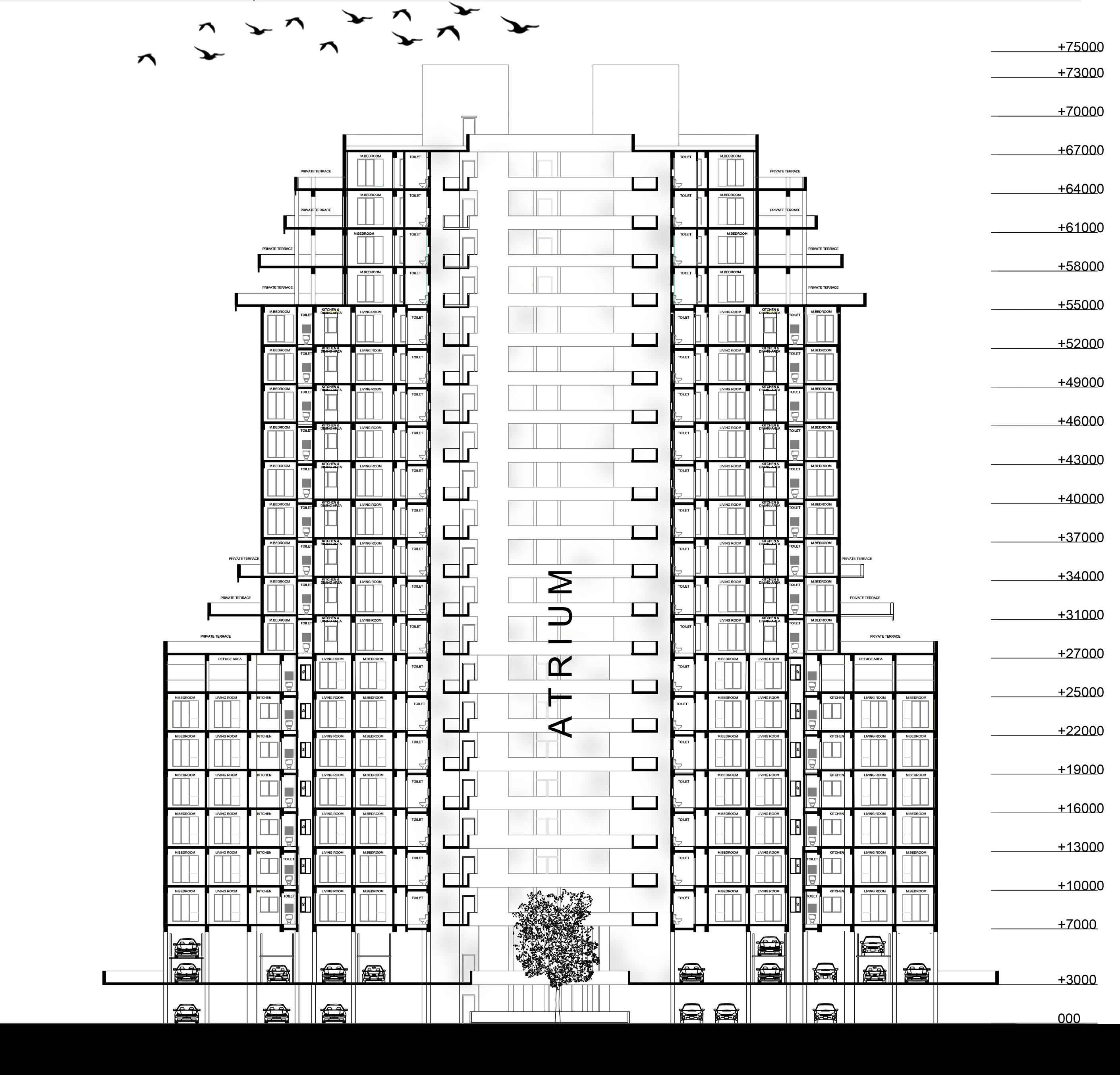
1 BHK - stack 2 BHK - stack 3 BHK - stack 1 2
3
4
5
6
SECTION XX’ 18
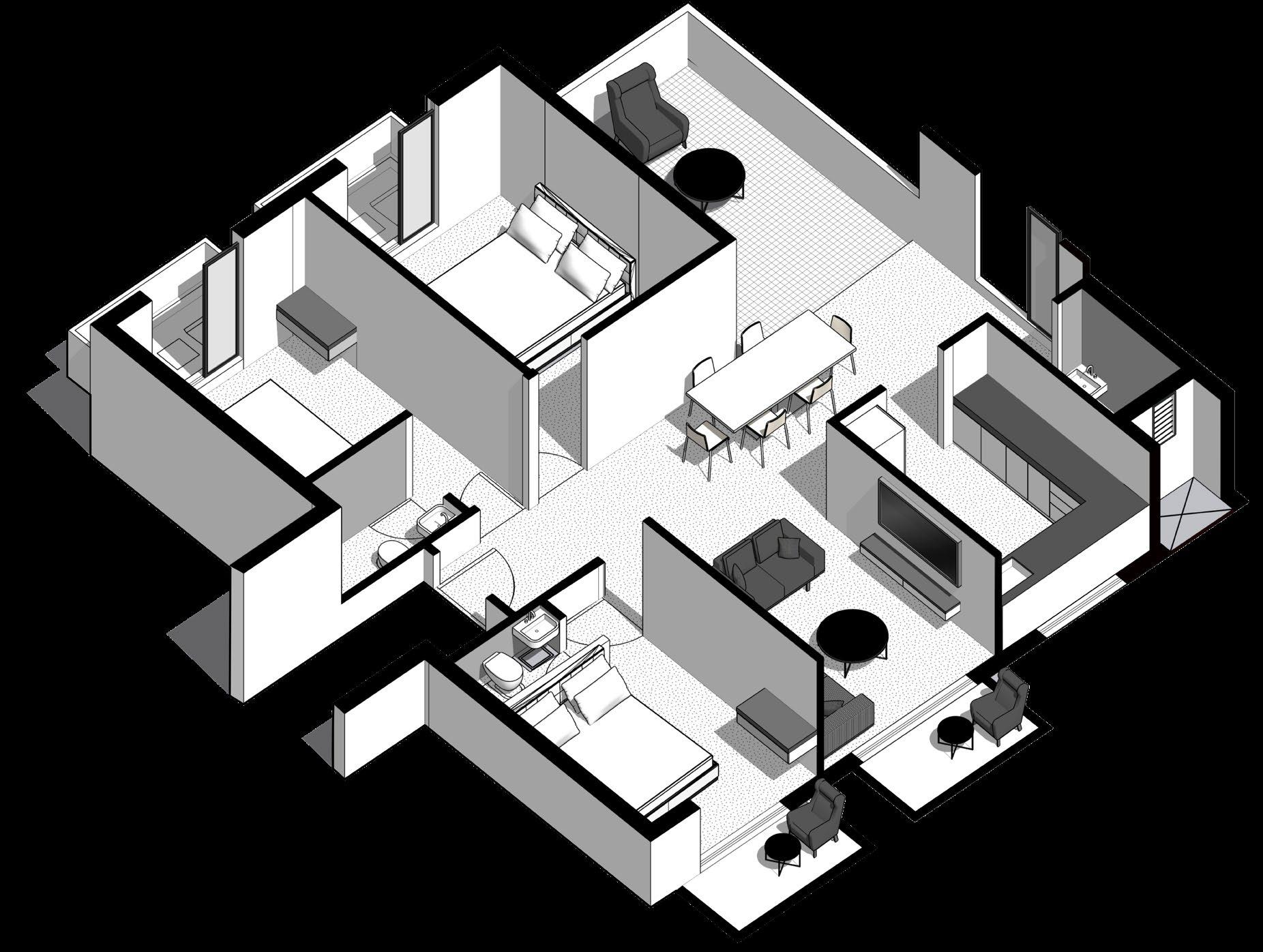
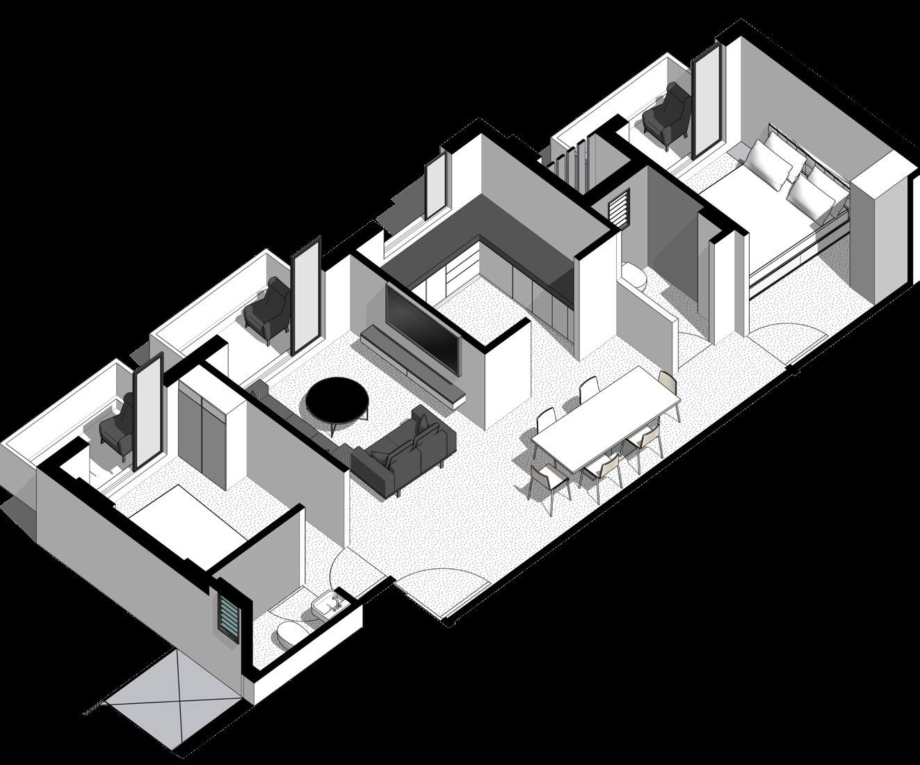
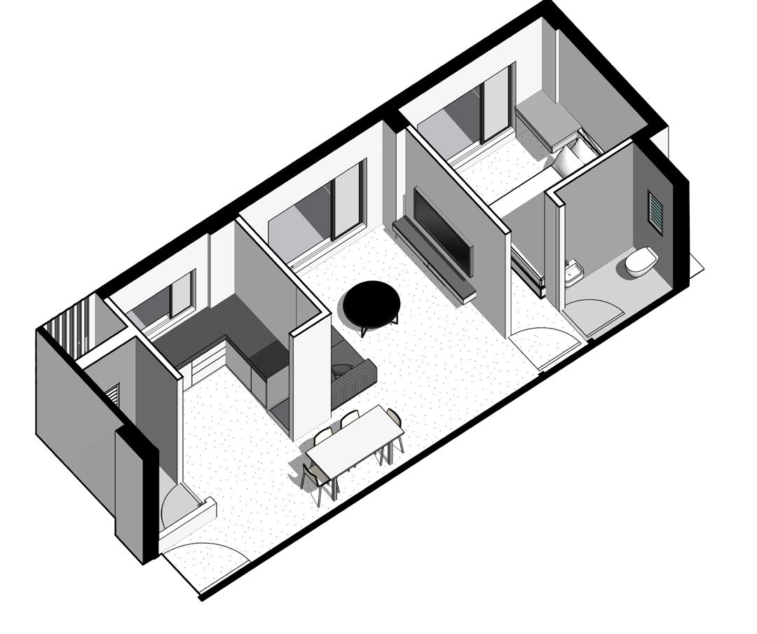
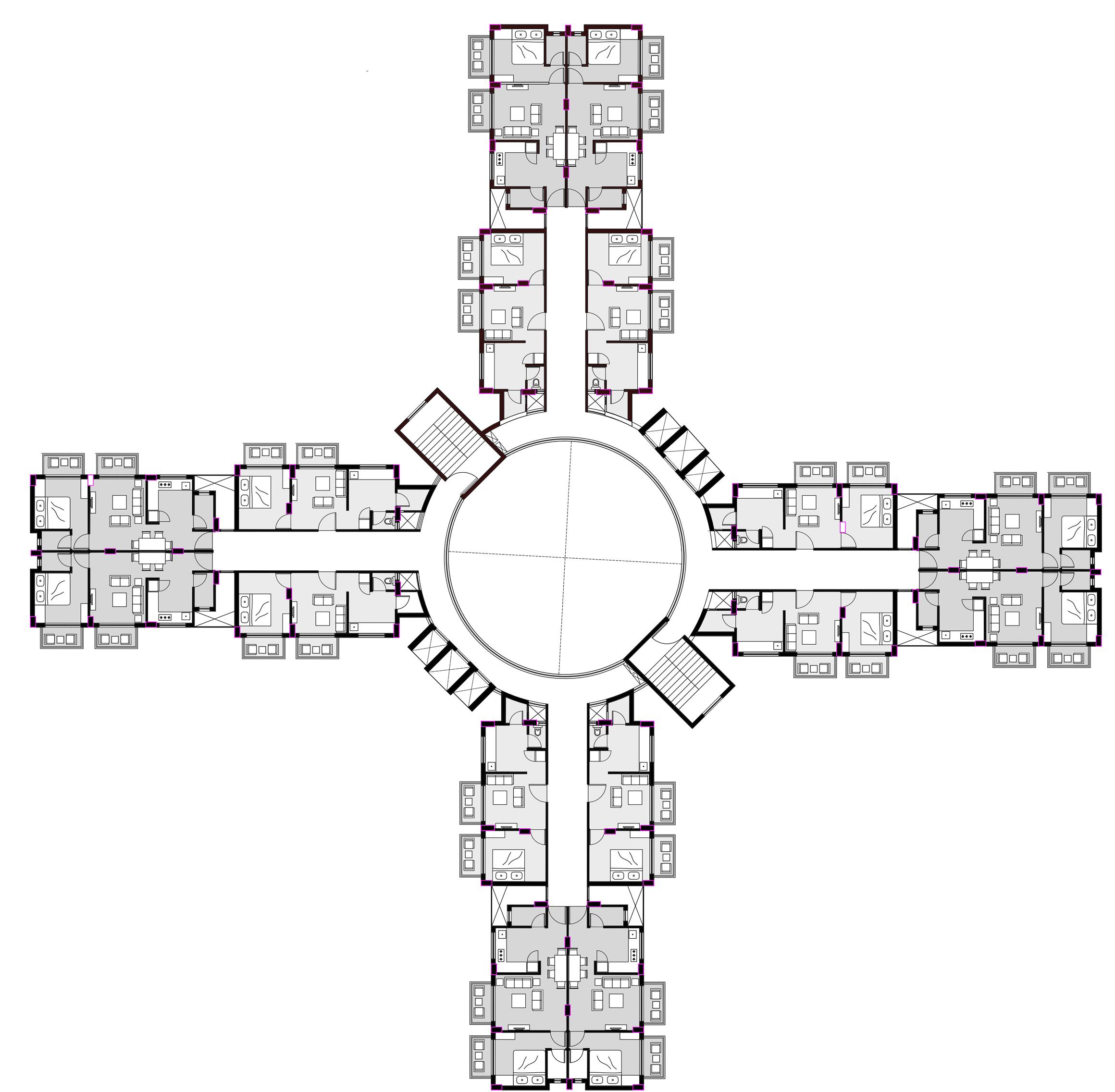
1ST- 7TH FLOOR PLAN (1 BHK UNITS)
17TH- 20TH FLOOR PLAN (3 BHK UNITS)
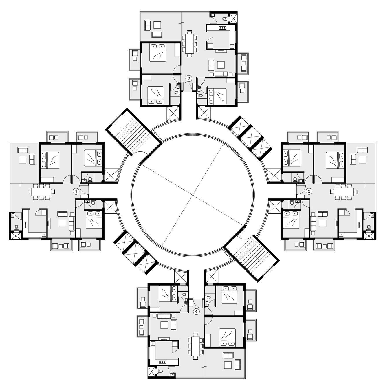
8TH- 16TH FLOOR PLAN (2 BHK UNITS)
1 BHK BLOCK- TYPICAL 2 BHK BLOCK- TYPICAL
3 BHK BLOCK- TYPICAL
19
2500 CL1 SK1 WL1+3 FL1 W3 OP1 A 6 8 START TILE 600MM CHAJJA PROJECTION ABOVE 38MM THK KADAPPA STONE BELOW HINDWARE S.S SINK VESSEL ( 600MMX450MM) 10MM THK SOMANY TILES 600MMX600MM 25MM THK GRANITE COUNTER-TOP LAID TO SLOPE 50MM WIDE FASCIA PATTI 1145 730 600 700 620 2100 1000 990 950 750 790 900 C 28 300 750 C 27 300 x 750 A 6 8 EQ A' A B' B C' C START TILE 600MM RCC CHAJJA 820 10MM THK KAJARIA KITCHEN DADO TILES (400MMX200MM) 10MM THK SKIRTING W3 38MM THK KADAPPA VERTICAL SUPPORT HINDWARE S.S SINK VESSEL (600MMX450MMX200MM) 300MM SUNK 150MM THK RCC SLAB DETAIL 'B' 3000 SECTION BB’ OF KITCHEN TYPICAL KITCHEN PLAN D4 W2 E ABULATION TAP NAHANI TRAP(100MM DIA.) FLOOR MOUNTED WC NAHANI TRAP(100MM DIA.) SCUBA WALL MOUNTED WASH BASIN 25MM DIA. FRESH WATER PIPE 100MM DIA. AIR VENT PIPE 150MM DIA. SOIL WASTE PIPE 150MM DIA. WASTE WATER PIPE 900 TILE DROP E 18 18 (445MM X 335MM X 135MM) START TILE KOHLER 4-WAY BATH AND SHOWER FAUCET CL1 SK1 WL3 FL2 A' A B' B C C' STAIRCASE SECTION TYPICAL TOILET PLAN NAHANI TRAP TOILET DETAIL LONG ARM UPVC PIPE JALI COVER FOR NAHANI TRAP STAINLESS STEEL PLATE PVC SOCKET D.P.C COATING BRICK BAT COBA 300MM THK. R.C.C. COLUMN UPVC DOWNTAKE PIPE BRICK WALL 10MM THK.SOMANY ANTI-SKID TILE SCREEDING PLINTH BEAM IN ELEVATION LOBBY STAIRCASE BLOCK LOBBY MID LANDING FLOOR LANDING WL1 FL1 CL1 SK1 STAIRCASE BLOCK ALL EQUAL RISER = 150MM TREAD = 300MM MID LANDING W5 FLOOR LANDING 200 MM BUND WALL
600 600 1500 LIFT MACHINE ROOM GROUND LEVEL 0.00 PLINTH LEVEL +0.6M FIRST FLOOR LEVEL +3.45M TERRACE FLOOR LEVEL +34.95M OHT LEVEL +40.08M WL1 FL1 CL1 SK1 ALL EQUAL RISER = 150MM TREAD = 300MM W1 W1 2600 20
FLUSHING WATER TANK DOMESTIC WATER TANK
Internship work
Firm name: RAW-NYC Architects, Dubai
Duration: 6 month // Nov’22-Apr’23
Contribution: Concept design, CAD planning, rendering and animation
3D modelling, research
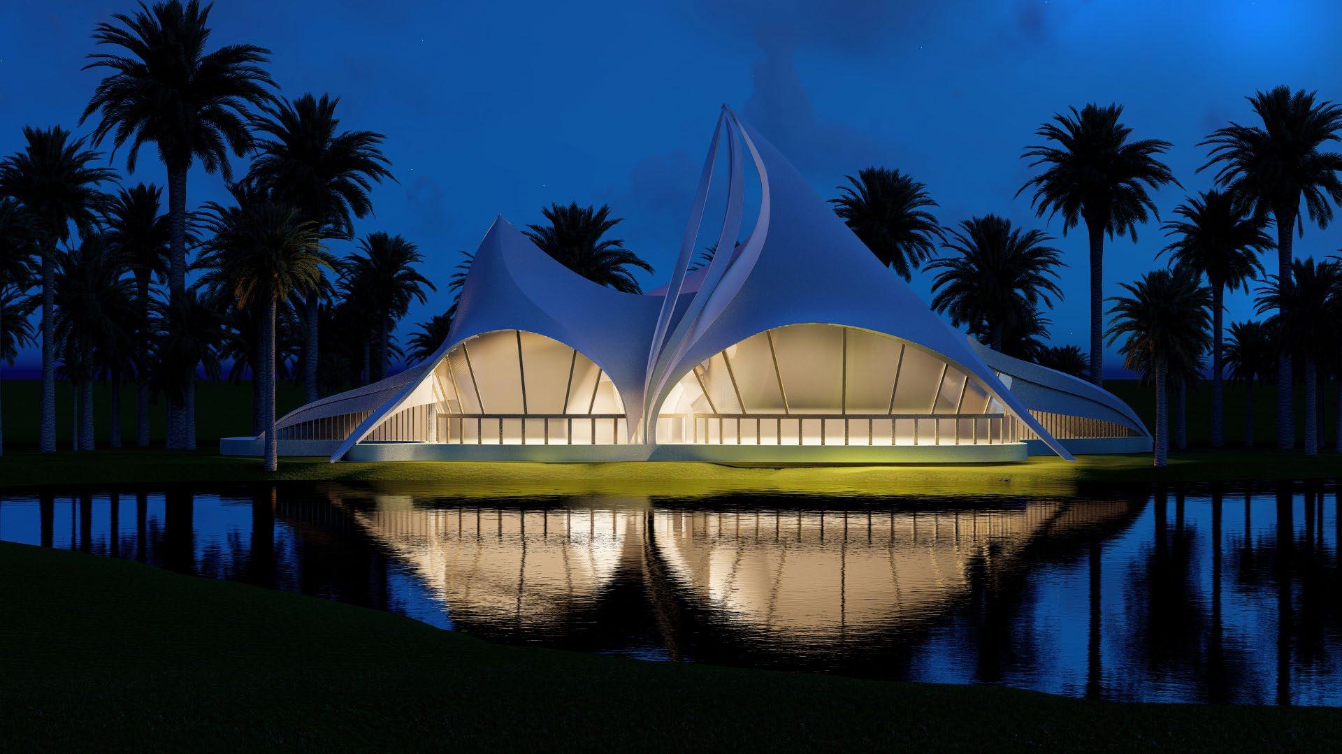
Projects: 1)The Desert Oasis, Saudi Arabia
2)The Boutique Hotel, Saudi Arabia
3)The Great Park Pavilions, Qatar
4)The Baghdad Bridge, Iraq
21
*In picture: The Desert Oasis
The Green bridge of Baghdad
Location: Baghdad, Iraq (In design stage)
Contribution: Concept design, 3D Modelling, research
Concept About
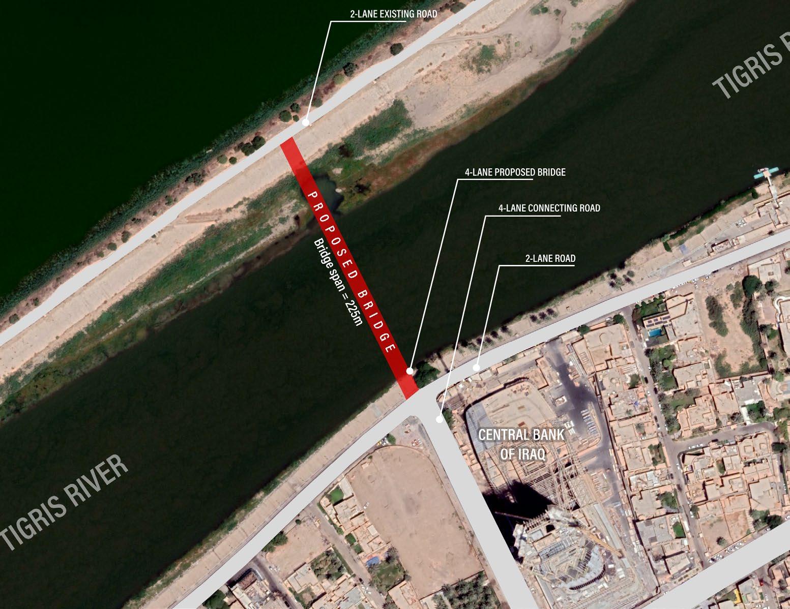
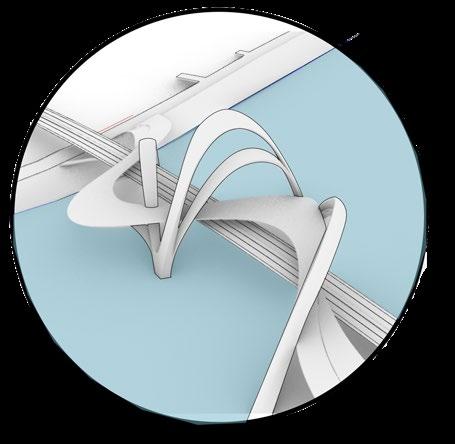
The Green bridge of Baghdad is the newest addition to the existing array of old bridges on the legendary river Tigris in Baghdad. The bridge will connect the eastern and western part of the city.
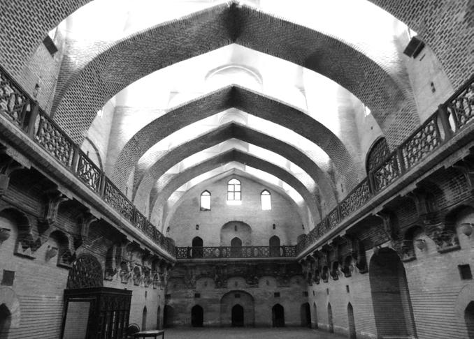
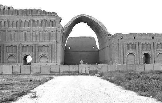
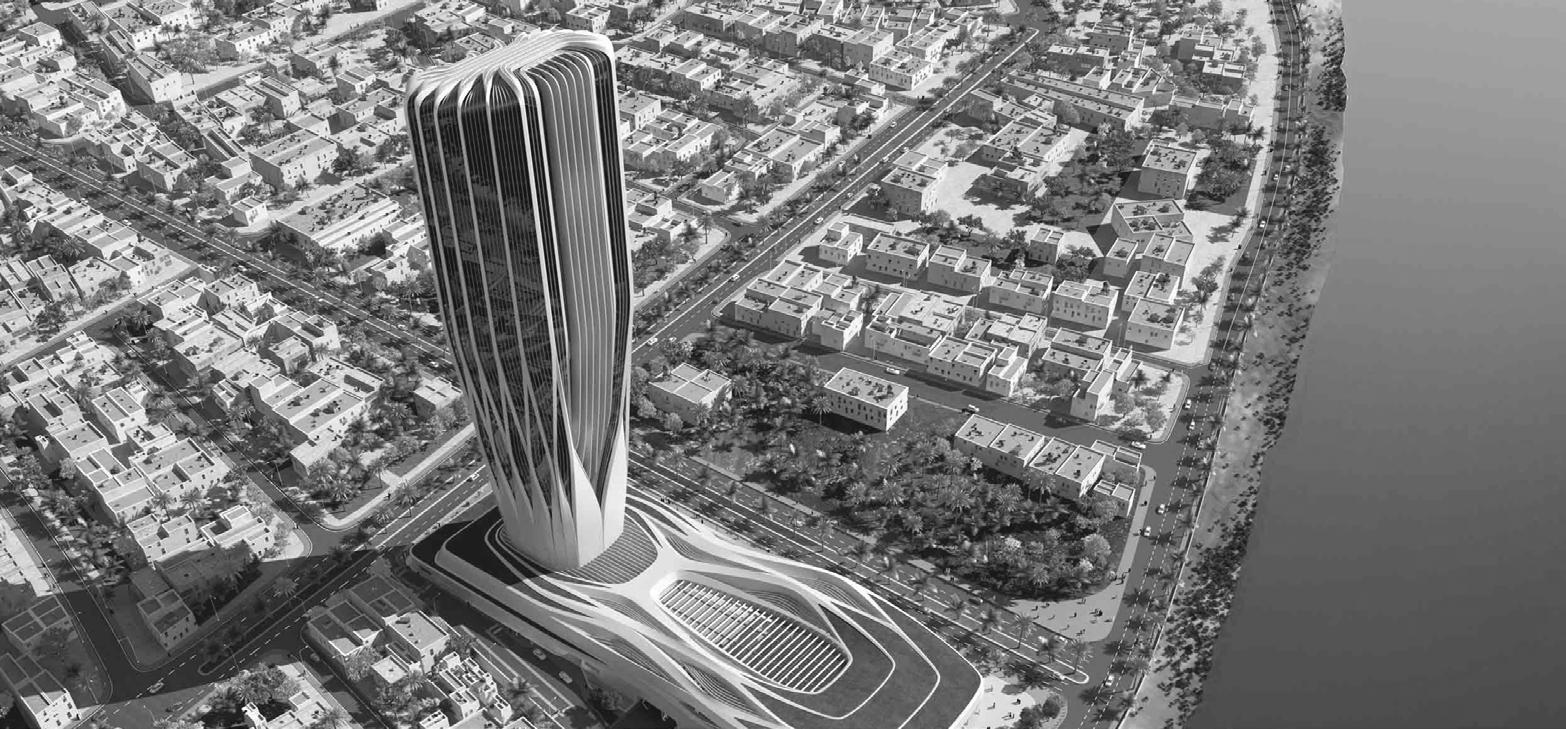
The design of the bridge is inspired by legacy of ancient arches of Iraqi architecture, paying homage to Mesopotamian civilization. Additionally, it seeks to honor the architectural style of Iraq-born architect Zaha Hadid, especially in connection to the nearby Central Bank of Iraq, designed by her. The bridge aims to symbolize Iraq’s forward-looking perspective while being firmly rooted in its rich historical legacy.
“Can a bridge be more than just a crossing lane? Can it also serve as a public realm?”
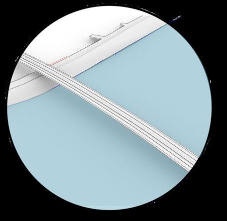
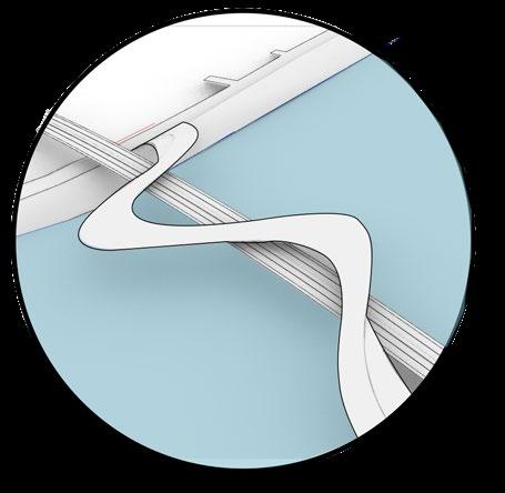
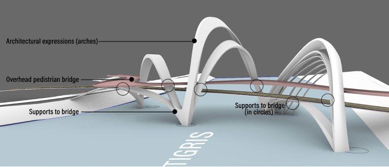
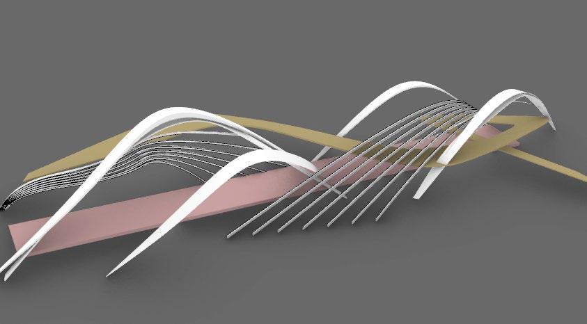
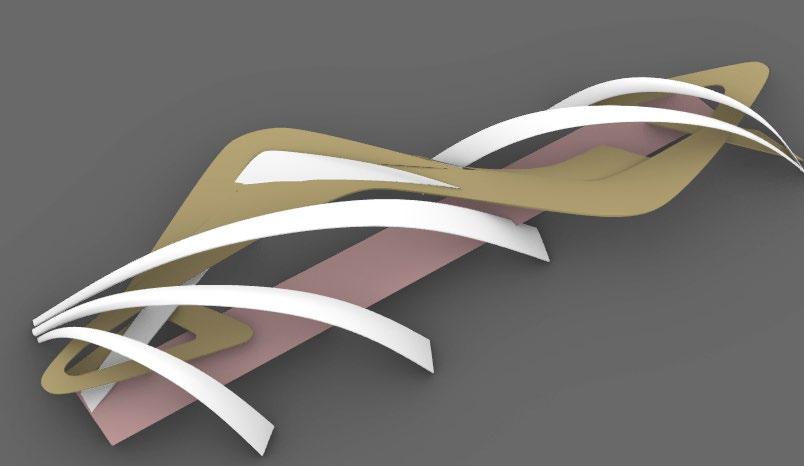
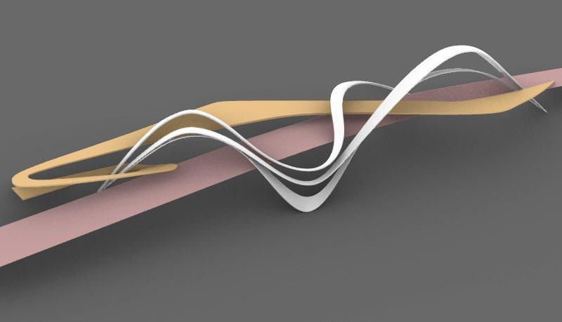
The central idea of the project was to design an engaging pedestrian bridge atop the vehicular bridge with arch like architectural expressions also acting as a bridge support.
Design variations
 Khan Murjum, Baghdad Taq Kasra arches, Baghdad
Central Bank of Iraq by Zaha Hadid, on the edge of proposed bridge
Khan Murjum, Baghdad Taq Kasra arches, Baghdad
Central Bank of Iraq by Zaha Hadid, on the edge of proposed bridge
path
22
Final design draft
4-lane vehicular road Pedistrian
Architectural expressions
Boutique hotel project
Location: Saudi Arabia (Design stage completed)
Contribution: Concept design, 3D Modelling, Interior design, CAD work, Rendering
About
A project envisioned to be a luxurious hospitality centre in the deserts of Arabia. It comprises of 4 blocks:-
A) The hotel
B) Retail block
C) Wellness centre
D) Entertainment centre
Role
My role as intern was to collaborate with seniors and design director to produce concept designs as per the guidelines given, along with animations and renderings for final presentation.
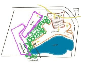
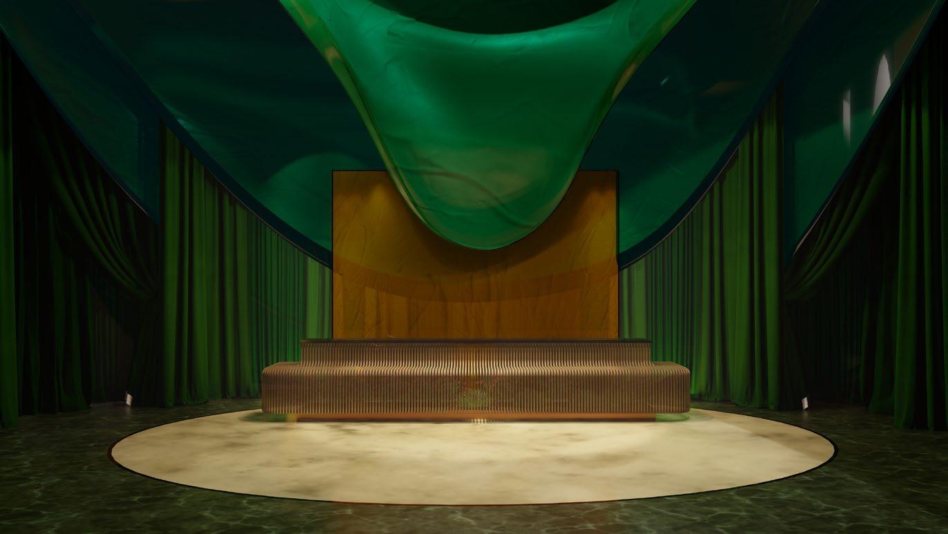
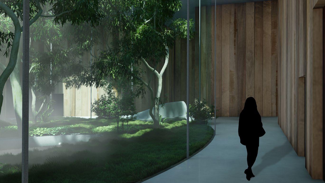
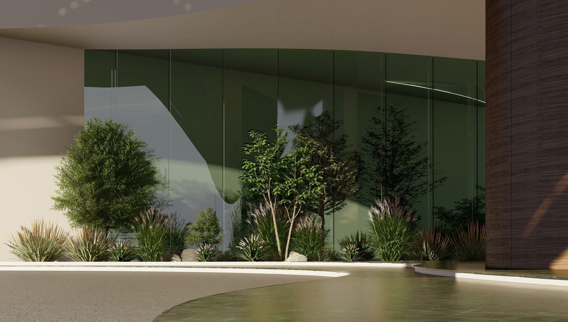 Initial concept sketch
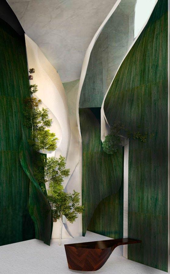
1 Images on the right: 1. Hotel reception unit design 2. Hotel ground floor lobby interior environment 3. Entrance 2
3 23
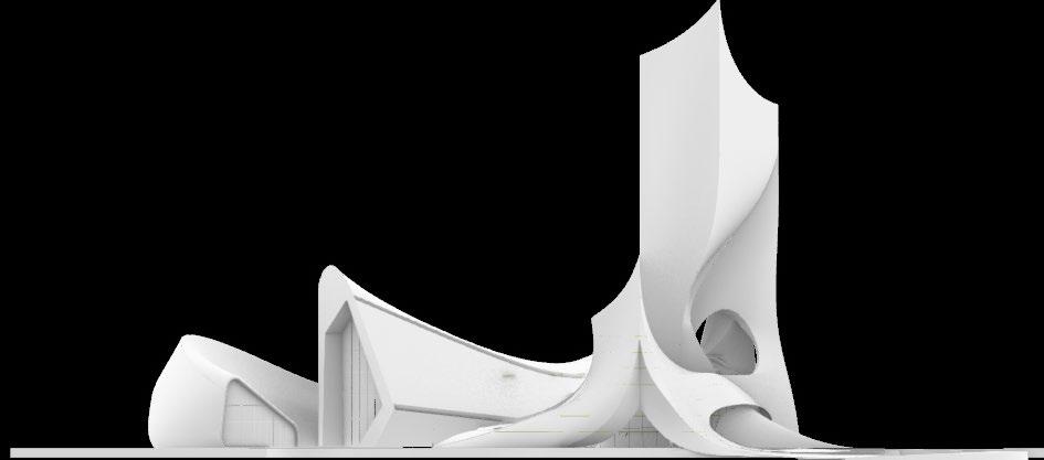
Hotel complex elevation

About:
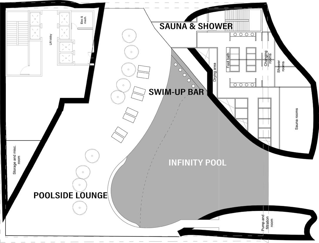
The hotel features an open area at podium level designed to house a swimming pool, a poolside lounge, and a bar. This elevated space offers a panoramic view, enhancing the overall experience for guests.
My Role:
• Designing the pool, bar opening facade, poolside lounge
• 3D modelling, visualisation and animation
About:
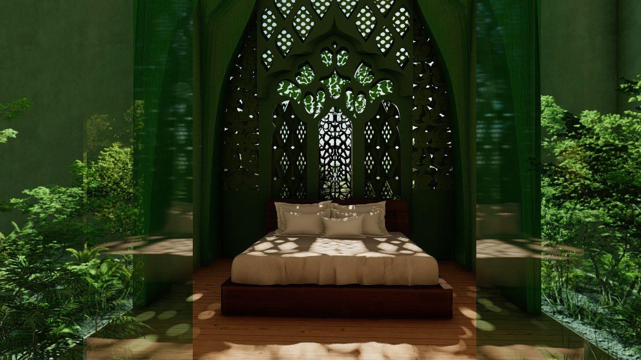
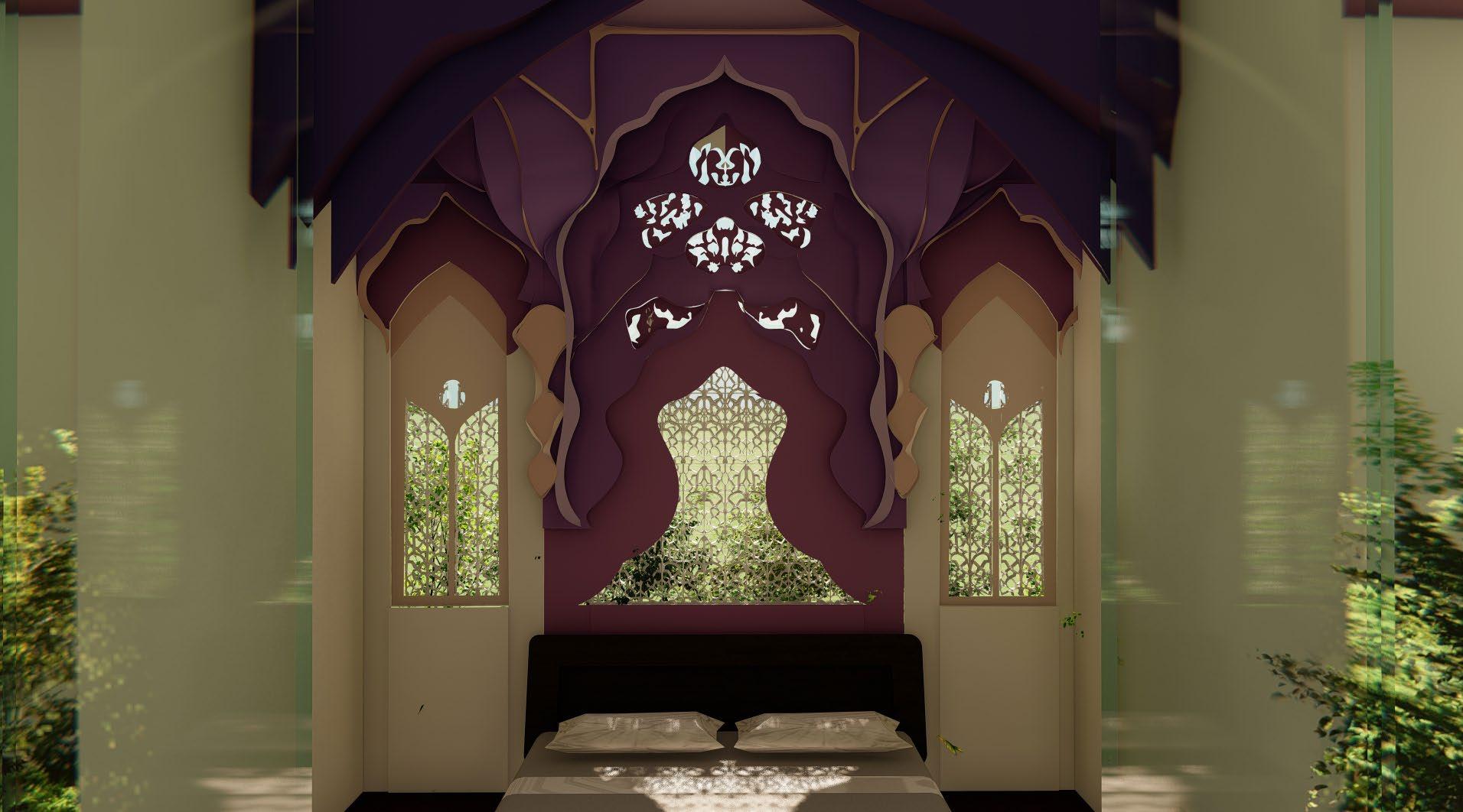
The hotel suites consist of two levels, including a mezzanine. They offer a lavish experience, with interiors blending fluidity and Arabic architectural elements, surrounded by lush greenery for a serene ambiance.
My Role:
• Designing the window wall unit and bed space
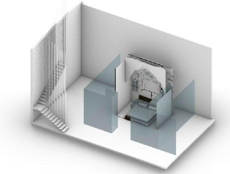
• 3D modelling, visualisation and animation
3D Model of lower levelBedroom
Sauna & shower
Infinity
Swim-up bar Building core
pool Poolside lounge
24
Pool & bar at podium
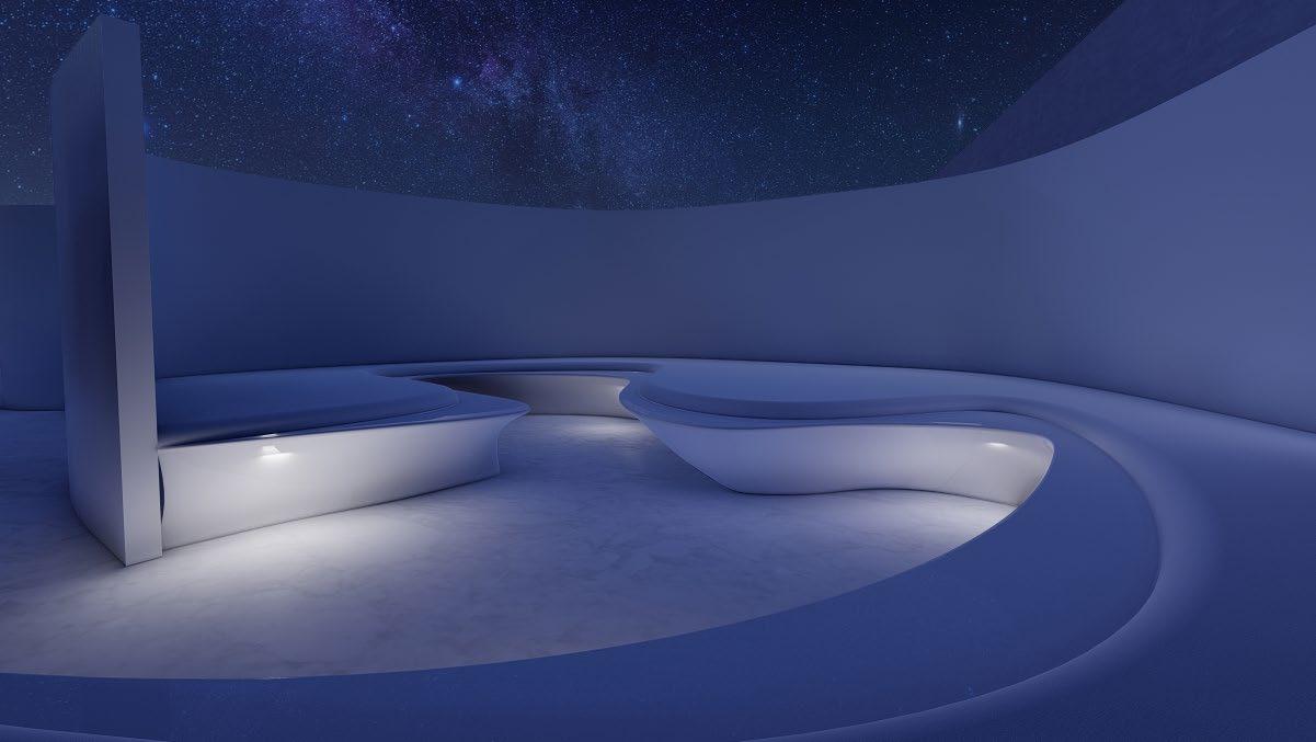
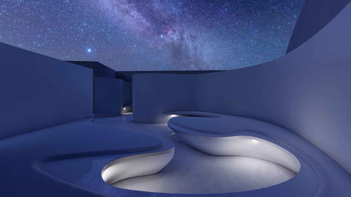
Sky meditation space - Wellness centre
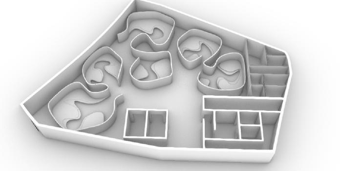
At the terrace level of the Wellness block, an open to sky meditation space is designed. It houses smaller pods that have lounges for meditation in solitude as well as in groups
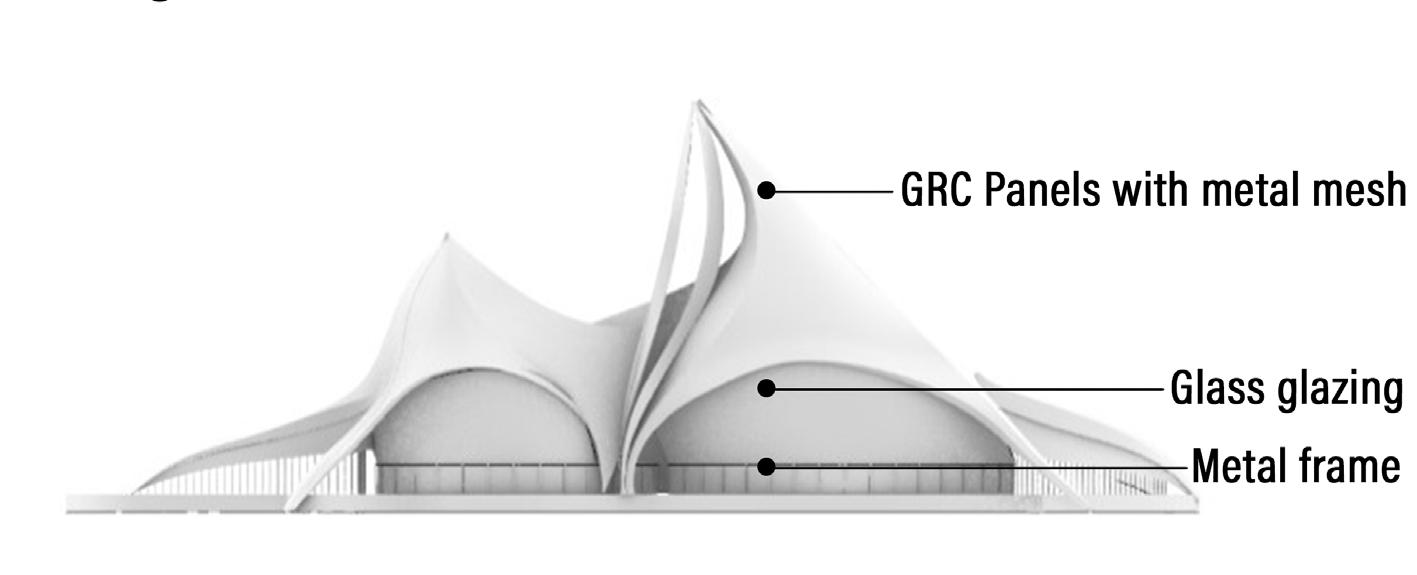
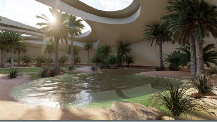
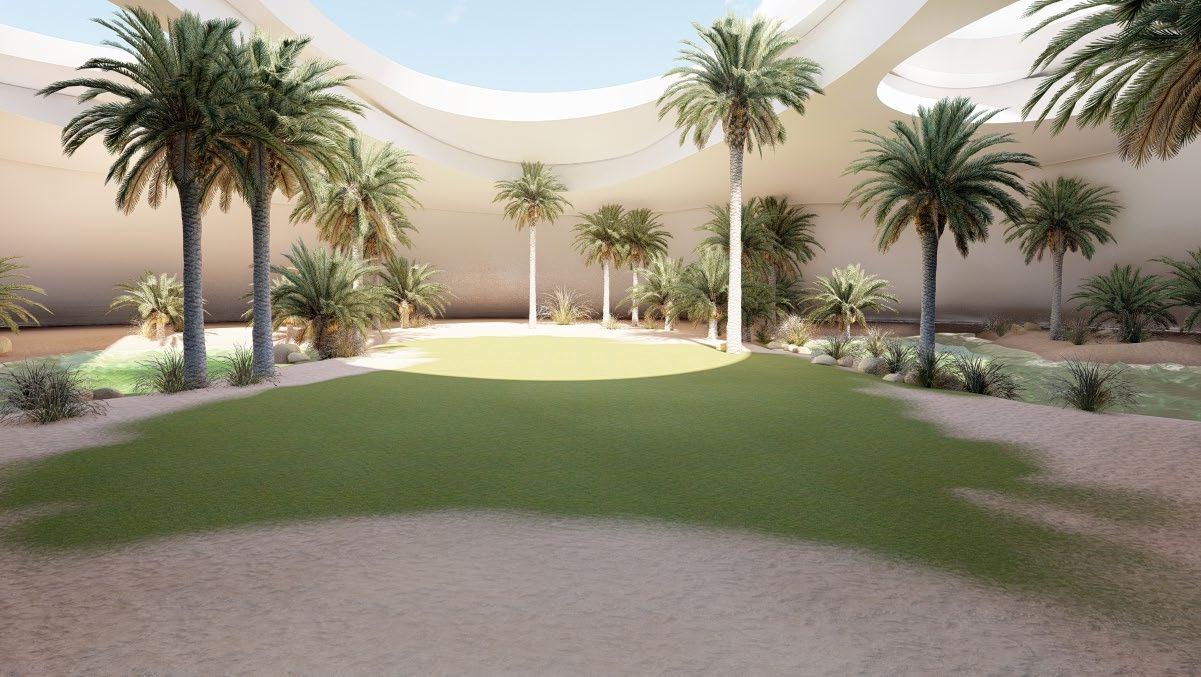
Desert Oasis pavillion
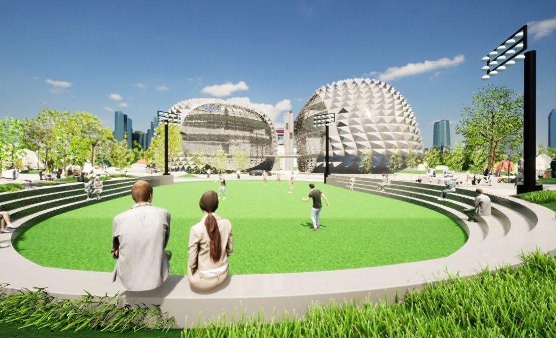
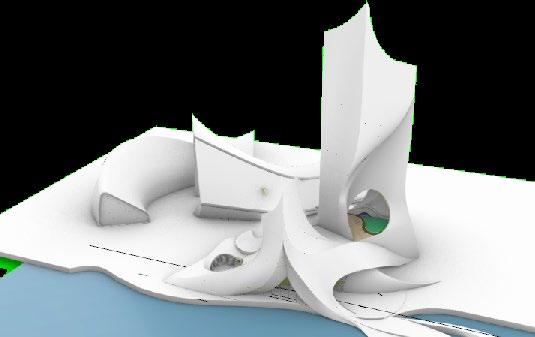
The Desert Pavilion is a distinct project featuring dynamically designed pavilions set in the desert. The architecture draws inspiration from an oasis style, complemented by landscaped ponds, enhancing the overall aesthetic and experience of the space.
Wellness centre reception unit design
25