of Masonry Construction
Design – Construct – Build

Ansgar Schulz
Benedikt Schulz
Manual
of Masonry Construction
Design – Construct – Build
Ansgar Schulz
Benedikt Schulz
Foreword
The first Manual of Masonry Construction, authored by Walter Belz and his collaborators, was published in 1984. The book helped entire generations of students to understand how to design and construct buildings with masonry units such as stones, blocks, and bricks. It conveyed knowledge on building construction, became part of the library of many architectural offices, and contributed to the success of the manuals published by DETAIL in a significant way. In the completely revised new edition of the Manual of Masonry Construction published in 2001, the team of authors headed by the architect Günter Pfeifer state in their foreword: “There is a strong indication that masonry construction will receive increasing attention in the building sector of the future. This method of construction has by no means experienced a decline in the late 20th century. Its perception and evaluation, however, lagged behind elegant metal, natural stone panel, and glass edifices. Today, we witness the need for a type of architecture that responds to anonymously controlled production technologies with a kind of building that reveals a personal touch – as masonry structures clearly demonstrate.”
Questions on construction and technology in the building sector have changed once more. The creation of new structures and the maintenance of existing ones are increasingly determined by issues of climate protection and adaptation to climate change. From a technical perspective, construction materials and types are not only evaluated according to parameters of structural engineering, building physics, and economic feasibility, but also sustainability criteria. These include resource consumption and the carbon emissions caused by production, transport, and assembly – as well as durability, longevity, reversibility, and recyclability in the context of a closed material cycle.
A look at the history of construction shows that masonry has met requirements of structural engineering, building physics, and economic feasibility in a sufficient way. The increasing consideration of sustainability aspects, however, is about to change masonry construction. The energy required for the production of masonry brick or block and the growing importance of reusing them are increasingly becoming the focus of attention. This includes how such units are assembled to create a certain type of bond and how masonry is integrated in multilayered wall constructions, with circularity becoming more and more important. Furthermore, not every form of masonry as such leads to a robust, durable construction.
From a design perspective and to a large degree, masonry construction remains as it ever was. The solid character of walls that form spaces, the sensual appeal of materials used for masonry, the traces of craftsmanship, and the feel and ornamental beauty of visibly exposed masonry bonds are attractive. They offer an emotional added value that defines the perception of the spaces people work and live in. The novel aesthetic of industrially produced masonry walls depends not only on whether the production method improves economic feasibility, but also on which aesthetically appealing visual impression these walls generate.
The point of origin of the architectural impact of masonry was, and is, the masonry unit, i.e. stone, block, or brick. Their size, proportion, material, and colour define opportunities for architectural design. By layering brick by brick, block by block, masonry walls can be created that sculpt designed spaces. The third new edition of the Manual of Masonry Construction is dedicated to this architectural principle.
Ansgar
and Benedikt Schulz
Masonry Design
Ansgar and Benedikt Schulz
Designing a visibly exposed or covered masonry wall is primarily defined by which role it plays as an opaque construction element in the context of the tectonic properties of a building. It can serve as a solid spatial delimitation or closed partial surface of a porous perimeter. It is also conceivable that masonry walls appear to emerge from the ground or are even elevated from it. The transitions between masonry and other building parts can contribute to the impression of a homogeneous building volume or an arrangement of contrasting individual elements (Fig. A 4.3).
It may seem obvious to consider masonry as a component of a solid building volume based on its high dead load and the layered principle of its assembly –even if the masonry itself has no loadbearing purpose. In such cases, the opaque surfaces are homogeneous, while other areas relevant to the design consist of openings and transitions between the interior and exterior. The tectonic image of a loadbearing wall requires a windowed facade, meaning the well-proportioned arrangement and formation of openings (Fig. A 4.1). Their borders and edges need to be designed. The lower border, i.e. the threshold or sill, can be either soft and thin or hard and solid. The reveals along the sides can mirror the design of the walls or be given emphasis by using specialised building parts. The upper delimitation can be formed using a straight lintel or a more or less curved arch. The shape and degree of detailing of the openings determines the visual appearance of a wall (Fig. A 4.4). The placement of a door or a window within openings is not only relevant in technological terms (see “Principles of Masonry Construction”, p. 8ff.). It is also relevant to
the design intention that a windowed facade expresses. If doors or windows are set back toward the interior of a building, the fact that the facade features openings is emphasised. If they are set close to, or even flush with, the exterior wall surface, the notion of a homogeneous building envelope is predominant (see “Residential towers in London”, p. 200ff.). Transitions between the masonry wall and the soil as well as the roof, meaning from vertical to horizontal delimitations, can either display a restrained or an emphatic expression, depending on the design intention that was implemented.
If masonry is employed as an opaque wall surface within an arrangement of deconstructed, fragmentary tectonics, for instance as a type of infill, the transitions
between it and other neighbouring wall sections consisting of different materials are decisive. Furthermore, the design of the masonry surface itself is of particular importance. Here, it is necessary to propose solutions in terms of the material, structure, and colouration of the visible surface. The tectonic context leads to understanding the wall less as a loadbearing part of a building and more as a purely design-driven element.
Covered masonry
If masonry is covered, the material characteristics of the units and the way they are assembled has no immediate impact on the design. Nevertheless, the particular
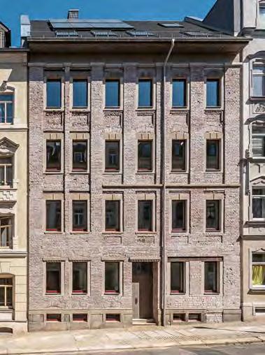
A 4.1 well-proportioned opening of a windowed facade, Casa Rossa Chemnitz (DE) 2020, Bodensteiner Fest
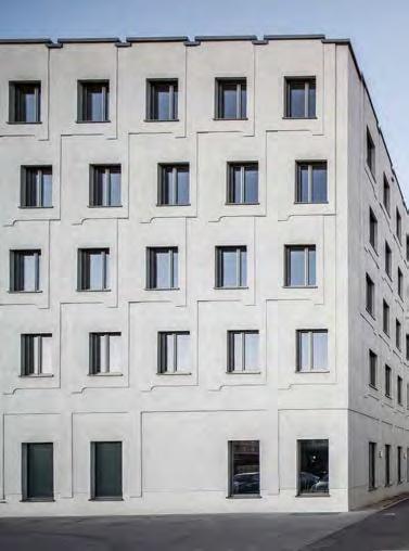
A 4.2 TICS facade with the traditional craftsmanship appeal of a rendered facade, office and commercial building Welfenstrasse, Munich (DE) 2013, Hild und K
A 4.3 contrast between planar and linear masonry elements, The International Rugby Experience, Limerick (IE) 2022, Niall McLaughlin
A 4.4 different options for the design of openings in a masonry wall
a emphasis on the opening, projecting course b emphasis on the lintel, flat arch c framing of the opening, circumferential border made of a different material
construction method can be relevant to the design intention. The bulk density of the units is important for their structural strength, the cladding or finish of the masonry wall, and the formation of the openings.
Units of high bulk density make it possible to create slim loadbearing shells. However, they require an additional thermal insulation layer that needs to be protected from weather impacts by an exterior layer. Typical wall constructions include thermal insulation composite systems (TICS) or back-ventilated curtain wall facades (see “Principles of Masonry Construction”, p. 10f.).
TICS facades convey the impression of a craftsmanship-based traditional rendered exterior surface, resembling a rendered
masonry wall. Technological requirements can be met with simple details. However, constructions become more complex when openings and transitions between the interior and exterior are emphasised by design. Manufacturers of TICS systems offer specialised building components capable of imitating traditional design patterns (Fig. A 4.2). Nevertheless, the feel of TICS facades is different to that of rendered masonry.
Masonry units with high bulk density make it possible to create large spans for openings, since bearings can absorb concentrated loads effectively. This strategy provides a large degree of design freedom for creating the visual impression of a windowed facade. The position of a door or a window in an opening is typically defined
in a manner that allows the insulation layer of the TICS system to cover the window frame. The window element is then centred within the opening, halfway between the interior and exterior, which leads to a neutral design expression. An arrangement flush with the exterior is demanding in terms of construction, since the element connected to the structural frame projects outward. This arrangement leads to complications in terms of building physics, because the connection between the window element and the TICS system is exposed to the weather. If the window element is arranged flush with the interior wall, the TICS system needs to be led around the corner along the reveal in a complex manner.
Masonry Structural Behaviour
Eberhard Möller
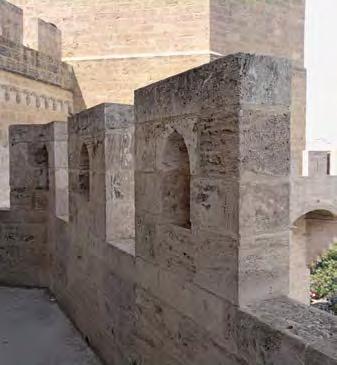
Masonry offers many opportunities for defining, delimiting, and protecting spaces. The construction methods, materials used, and their expression are equally diverse. The term “wall” is derived from the Latin word “vallum”, meaning rampart or fortification. Historical structures such as castles, defensive city walls, or the Great Wall of China exemplify the protective functions of masonry and brickwork (Fig. B 1.1, B 1.5).
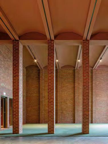
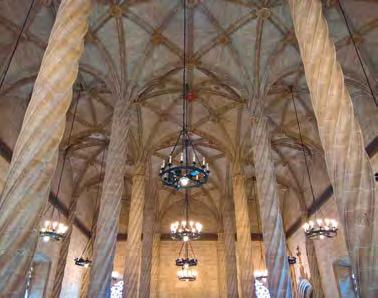
Masonry units – whether stone, block, or brick – are essential elements of masonry. Stone, especially natural stone, has been considered an exquisite and robust material since antiquity. As a predominantly vertical element, masonry is used in the construction industry for walls and less often for pillars (Fig. B 1.6).
Walls often perform many different functions. Aside from loadbearing and stabilising purposes, they offer protection from view, noise, weather impacts, moisture, heat loss, and fire. At the same time, walls are intended to be visually appealing, permanent, cost-
efficient, and require very little maintenance. Given current specifications, a single wall layer and a single material are seldom sufficient to meet all or at least many of these functions. Often, planners use multi-leaf or multilayer masonry – or combinations of both – for interior, exterior, or party walls. Masonry walls are created by the successive layering of masonry units in courses. For a long time, this required manual labour (see “Craftsmanship-based assembly”, p. 48f.). Today, machines, robots, and drones are used for this purpose (see “Machinesupported production and prefabrication”, p. 50ff. and “Robotics”, p. 54ff.). To receive a first impression of how masonry walls behave structurally, it is helpful to try stacking elements. Experience soon shows that smooth walls lose stability when they become too tall or too slender. Minor shocks or limited horizontal loads due to wind or impact by an object can lead to the collapse of slender walls. Corners have a clear stabilising effect when two walls are joined and interlocked. Vertical loads can, in certain cases, contribute to an increase in stability.
In principle, every building and every loadbearing element it comprises should be constructed and erected in a manner capable of bearing its own weight and all horizontal and vertical loads it is subject to. The forces acting on a building need to be resisted by the structure and, ultimately, transferred into the soil to ensure stability and equilibrium. Aside from structural integrity, structural engineering needs to consider aspects such as suitability for use, durability, and cost-effectiveness.
Unlike frame construction methods that are commonly used for timber, steel, or reinforced concrete structures, masonry follows
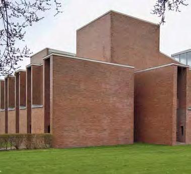
the principle of cellular construction and less often crosswall construction. Based on the large solid mass that masonry walls comprise, building with masonry is considered a solid construction type (Fig. B 1.2).
Load transfer
All actions, regardless of cause or direction, need to be in equilibrium with the capacity of the soil to bear loads. For this purpose, different loadbearing and stabilising elements, such as ceilings, walls, columns, beams, frames, or bracing systems need to be arranged and combined in a sensible manner. The loadbearing structure makes it possible to transmit the loads acting on the building into the foundations and below, into the soil.
Stabilisation
Building parts that are described as having a stabilising effect include those capable of bearing horizontal loads, including earth pressure, wind, or impact by an object. Horizontal elements such as ceiling slabs require three vertical building elements per floor that may not be arranged parallel to each other. Their direction of action must not intersect in one point (Fig. B 1.3).
Typically, in the case of masonry construction, such stabilising building parts are wall plates. In principle, frames, bracing systems or fixed columns are also possible (Fig. B 1.7).
For masonry, verification is required whether a building under planning features an obviously adequate amount of sufficiently long stabilising walls in a longitudinal or lat-
Eberhard
Möller
Eberhard
eral direction that are connected to the foundations without greater interruption or offset. In such cases, mathematical verification of stability can often be omitted. The length lw of stabilising walls for a floor height h needs to be at least l w ≥ h/5. The thickness t needs to be at least one third of the thickness of the bordering wall requiring stabilisation and not less than t = 11.5 cm. For this purpose, walls should be erected in bond or connected by other construction methods resistant to compressive and tensile forces.
Ceilings consisting of cross-laminated timber or reinforced concrete can serve as horizontal stabilising elements. Timber beam ceilings, ribbed ceilings, or hollow core slabs are also capable of stabilising a structure. They require effective measures to create stiff plates, such as attaching woodbased material panels with suitable connectors. Ring beams serve to connect ceilings to vertical masonry walls, creating connections resistant to compression, tension, and shear. As an alternative to ceilings that function as stiff plates, sufficiently rigid, circumferential ring beams consisting of reinforced concrete and confirmed by structural verification can be arranged at ceiling height within exterior walls (Fig. B 1.4).
B 1.1 protective masonry walls, Torres de Serranos, Valencia (ES) 14th century
B 1.2 solid masonry construction, First Unitarian Church of Rochester (US) 1962, Louis I. Kahn
B 1.3 possible arrangement of walls as stiff vertical plates
B 1.4 structural effect of a ring beam
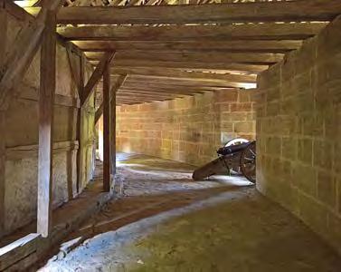
B 1.5 gun gallery, Spital Gate in Rothenburg ob der Tauber (DE) 16th century
B 1.6 slender pillars, Lonja de la Seda, Valencia (ES) 15th century
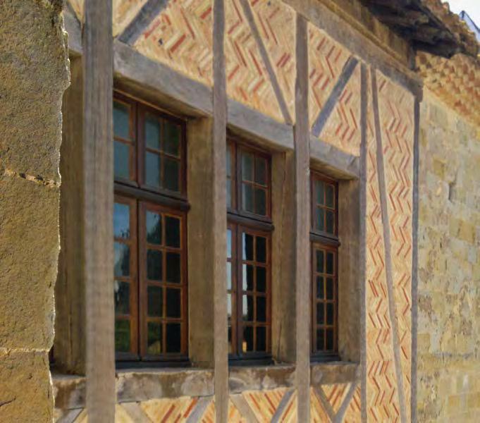
B 1.7 half-timbered structure with timber bracing and masonry infill, Château de la Cité de Carcassonne (FR)
Robotics
To date, robotics has been unable to establish itself as a state-of-the-art method in the building sector. During the last two decades in particular, numerous applications have been developed and studied. The research approaches introduced below show how challenges in the design and construction of masonry can be addressed in different ways by using robotics. Potential advantages and existing challenges will both be subject to analysis. The coming years will show how the respective technologies will be advanced and which of these will prevail in the long term.
From research project to routine use?
Industrial robotic arms have existed since the 1960s. Their development was advanced in particular by the automotive industry, where they continue to be in broad use. For the manufacturing of vehicles, robotic arms perform logistical tasks, work in the production line, assemble components, and act as welders. However, these linear machines are unsuitable for immediate use for architectural and design purposes.
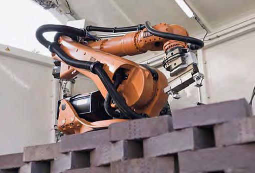
The works of Gramazio Kohler Research at ETH Zurich show that industrial robotic arms can also be used for architectural design purposes. They have demonstrated their capacity to support non-linear production processes in order to research flexible and iterative adaptation measures. As early as 2005, the research institute installed an industrial robot at the chair (Fig. C 3.1). In their first project, the team tested the use of modern building technologies in the design of masonry. This was the basis for
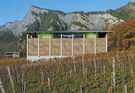
creating the facade of Gantenbein Winery is Fläsch, Switzerland, which was completed in 2006 (Fig. C 3.2). The project demonstrates how robotics can execute traditional building processes such as bricklaying in technologically different ways and thereby expand the scope of architectural design.
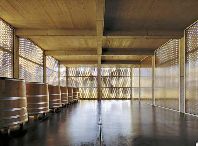
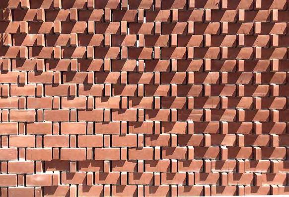
The facade consists of prefabricated masonry elements that were successively integrated in the concrete frame of the winery structure (Fig. C 3.2). The work was completed using a non-standardised process in which no single masonry component matches the other. Together, however, they establish a comprehensive image. Based on a computer-generated design, a three-dimensional pattern resembling a grape was created and implemented by slightly offsetting the clinker brick within a masonry wall featuring open joints. The facade sections were prefabricated with high precision by an industrial robot at ETH and assembled on the construction site. In order to simplify transport to the site, the robot laid the bricks of each wall section on top of a reinforced concrete pedestal. Instead of mortar, two-component adhesive was used. The result is a facade based on a completely new procedure. It also meets the lighting and climate requirements of the winery – constant daylight and circulation of ambient air facilitated by the open gaps in the masonry wall.
In the research project “Climate-Resilient Robotic Facades” at TU Munich, based on a case study conducted in 2020, new opportunities for computer-based production in the field of climate-resilient construction were tested (Fig. C 3.4). Self-shading brick formations were studied in order to develop a
facade that can prevent heating up to a large extent and reduce heat emission into the surrounding urban space. Based on computer-assisted climate simulations, multiple individual and non-standardised brick facade designs were tested prior to implementation. A full-scale prototype of a two-metre-tall and three-metre-wide facade section was built by a robot that collaboratively interacted with the surrounding environment (Fig. C 3.3). The robot’s range is 1.30 m. In order to avoid relocating it repeatedly, the wall was divided into different sections. This study is a further example of how new approaches to robot-assisted production aim at quickness, precision, and aspects related to design, climate, and function [1].
In addition to the new opportunities offered by non-standardised and parametric work processes enabled by robotic arms, numerous further reasons explain why machines and especially digital production methods have significantly gained importance in the building industry over the past two decades. Parametric work refers to the
C 3.1 prefabrication of a masonry facade using an industrial robot, Gramazio Kohler Research, ETH Zurich
C 3.2 facade, expansion, Gantenbein Winery, Fläsch (CH) 2006, Bearth & Deplazes a winery facade b interior view
C 3.3 self-shading brick facade, research project “Climate-Resilient Robotic Facades”, TU Munich, School of Engineering and Design, Chair of Building Technology and Climate Responsive Design, Professorship of Digital Fabrication
C 3.4 Climate-Resilient Robotic Facades: a mobile robotic arm assembles a brick wall step by step from eleven different positions
Gramazio Kohler Research, ETH Zurich
Lotte Schlör, Andrea Uhrig, Dirk Bayer
computer-assisted formal and organizational application of statistical key values and their interdependencies.
Creating masonry is becoming increasingly subject to variable influences, obstacles, and limitations. For instance, climate change is placing new requirements on the building sector. These days, masonry needs to be able to resist increasingly extreme weather conditions. It also needs to be built more quickly, more efficiently, and more precisely. In return, this justifies expanding research in the field of robot-based construction. The persistent lack of skilled staff leads to delays in many construction projects across the globe – a further reason to accelerate research in robotic bricklaying. Even when handling heavier masonry units, robots are able to work more quickly and precisely than people and can do so around the clock. Less workers would be required and construction tasks could be potentially completed more quickly and cost-efficiently.
The challenge of processing mortar
We have not yet reached the point at which only robots construct our buildings. Until then, we still have a long way to go. A completely automated process of masonry construction cannot yet be realised. One large factor in play is, for instance, processing mortar. Robots have the capacity to quickly and precisely lay brick. Handling mortar, however, remains a challenge. Tasks such as grouting masonry joints, setting masonry units in a mortar bed, and removing excess mortar require exceptional degrees of robot system flexibility and adaptivity.
Gramazio Kohler Research opted for a special adhesive to join masonry units together for the prefabricated masonry wall
Ralph Feiner
Thermal Insulation, Moisture Protection, Comfort
Lukas Lauss, Roland Göttig
Beyond essential requirements such as structural stability or fire protection, there are other necessities that are determined by the usability of a building. These include minimising heat losses in winter and protecting users from excess heat gains in summer. A further aim is to prevent possible damage due to moisture. At the same time, users expect comfortable, hygienic indoor conditions throughout the year, also supported by the framework conditions of building physics.
Economic and climate policy aims relevant to our societies can be achieved by minimising the energy consumption of buildings and thereby reducing the amount of structural damage that may require expensive repairs. Here as well, aspects of thermal insulation and mosture protection play a key role.
Thermal insulation and moisture protection
Even for simple construction types, such as those common in Germany well into the 1960s or even 1970s, the aim was to avoid structural damage. For this reason, minimum normative requirements for thermal insulation and moisture protection were formulated back in the immediate post-Second World War era [1]. The interrelation between the two protection goals will be explained in the following: the higher the thermal resistance of a building component RT [m2K/W] when exposed to low temperature conditions on its exterior, the lower the heat loss in winter across the surface of the building component. However, the interior surface temperature of building components must not become too low along window frames,
interior corners, and similar thermal bridges. Otherwise, moisture-related damage due to excess relative humidity ϕ [%] and condensation (ϕ = 100 %) are to be expected. The corresponding absolute humidity c [kg / m3] in interiors is due to existing exterior air humidity plus the share contributed by moisture sources such as cooking, showering, washing and drying laundry, watering plants, or human breath. For interiors with an indoor air temperature of 20 °C a relative humidity of 30 % is assumed, based on the moisture content of the outdoor air. An increase to 50 % is assumed due to moisture sources inside apartments. Thus, adequate thermal insulation that increases the temperatures of interior surfaces of planar building components and thermal bridges also contributes to better moisture protection. In this simplified form, it is only the case if exterior insulation is used or an uninterrupted insulation layer is planned for the loadbearing layer, such as for monolithic masonry construction. For interior insulation or an unfavourable transition between insulated and uninsulated building components, significant effort is required to prevent indoor air from reaching cool spots –either completely or as far as possible. Otherwise moisture is likely to accumulate
Wintertime thermal insulation
In the past decades, the requirements for thermally insulating building envelopes in wintertime have become increasingly strict, with particular reference to transmission heat loss (HT) and ventilation heat loss (HV). The latter cannot be minimised arbitrarily due to minimum hygienic requirements for air exchange in buildings [2]. In parallel, requirements for technical building services
exist that enable heating, cooling, ventilation, and in special cases humidification and dehumidification. In countries such as Germany, where residential buildings comprise the majority of building stock and consist of masonry to a large extent [3], mechanical heating and ventilation consume the most energy of all building services.
Today, in wintertime, thermal insulation predominantly serves to reduce energy consumption in the building sector. The 1995 Thermal Insulation Ordinance [4] pioneered a comprehensive system of requirements for building envelopes in combination with building services as the basis of energy performance certificates. Therefore, masonry block with a lower density or a higher share of air pores was manufactured or equipped with additional layers of insulation. Both contribute to lower U values. For this reason, the production of regenerative energy in or on buildings was included in the certification process. In past decades, the requirements for the energy demands of residential buildings (from 2002 onward also for nonresidential buildings) were continuously tightened (Fig. D 1.2). This development came after insight was gained in pilot projects and research structures.
However, the observation was made that the most recent tightening of regulations for the minimisation of building energy demands no longer meets economic basic preconditions that follow the Pareto principle [5] (Fig. D 1.4, p. 64). Beyond that, clear systematic and statistical deviations exist between the calculated and actual energy demands of buildings [6]. While statistical deviations can result in both positive and negative shifts relative to actual values, systematic deviations mean that measured
values differ from calculated ones in an either positive or negative manner. The extent and the causation of deviations were researched by the German Environment Agency (Umweltbundesamt) in detail and published in 2022 (Fig. D 1.3). The research also discusses prebound and rebound effects. Prebound effects indicate that the calculated energy demand of buildings of lower energy efficiency is higher than in reality. In contrast, the rebound effect states that the calculated energy demand for highly efficient buildings is lower than in reality.
The discrepancy between the two energy demand parameters identified in the course of building planning and the energy consumption value that is measured during operation is described as an energy performance gap. Research shows that a variety of factors contribute to it, including unexpected user behaviour (user/usage gap,
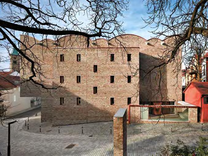
D 1.1 art museum in Ravensburg (DE) 2012, LRO
Lederer Ragnarsdóttir Oei
The new construction at the fringe of the historic city was the first museum building in the world to achieve the passive house standard. This was a challenge due to the low degree of fenestration – and thus low solar gains. The facade bricks were sourced from a demolished cloister complex in Belgium.
D 1.2 development of minimum requirements for energy demands in residential buildings: the grey fields show the legally required minimum standard for buildings with an A/V ratio ranging between 1.1 (one-storey single family house with L-shaped floor plan) and 0.35 (multi-storey residential construction). The dots along the continuous line indicate energy standards of research buildings erected at the indicated time.
D 1.3 comparison, actual energy savings and calculated savings for renovating residential buildings
Sustainability
Martin Zeumer
Overview
Masonry is both durable and long-lasting. It is robust and thus seldom requires renovation or replacement. Compared to other construction materials and methods, masonry needs little care or maintenance, greatly reducing the consumption of materials and energy. Furthermore, masonry develops a patina over time, which means it requires very little cleaning. In many cases, the visible process of aging provides masonry constructions with a timeless impression. Maintenance work can focus on minor aspects, further conserving resources. Beyond that, masonry units – made of either loam, brick, concrete block, lime-sandstone, or natural stone – typically consist of local mineral raw materials. This shortens the transport routes for loam, clay, sand, or lime and minimises carbon emissions.
During its life cycle, masonry effectively stores heat. The storage mass also helps to conserve heating energy in winter and keep buildings cool in summer. By moderating temperature amplitudes, the material also stabilises humidity, which contributes to a comfortable and healthy residential climate [1]. Moreover, many masonry material types feature a rather low pollutant content.
Demolition waste such as brick or concrete rubble can be reused as recycled construction materials and deployed for new construction projects. Masonry is already embedded in a circular economy model that is still in the process of establishing itself. However, this development is necessary. The majority of building stock in countries such as Germany consists of masonry. This is also true for new construction: in 2023 more than 65 % of residential building
stock cubage was established by means of masonry construction.
Distinguishing the sum total according to material, the related shares were 28 % brick, 24 % lime-sandstone, and 14 % aerated concrete [2]. Yet, the overall percentage of masonry has been declining for decades (Fig. E 1.3) [3]. Conventional new construction is under pressure – in terms of both economy in the sector and technologyrelated innovations. Furthermore, the production of masonry contributes to a significant amount of carbon emissions.
Developments within the masonry sector
Can masonry be sustainable? The Federal Association of Calcium Silicate Bricks (Bundesverband Kalksandstein) asked this question in late 2024. A short-term study served to research the performance of masonry buildings within a life cycle assessment [4]. The result: buildings made of limesandstone block can meet requirements for building certification according to, for example, the German Quality Seal for Sustainable Buildings (Qualitätssiegel für nachhaltige Gebäude, QNG) without difficulty. The verification took place in the PLUS quality range (minimum requirement) without compensating the construction-related material expenditure by low-emission operation. As a result, masonry can be considered a suitable construction method for sustainable buildings. Nevertheless, detailed observation is necessary in order to comprehensively evaluate the sustainability of masonry.
The masonry sector is certainly aware of its impact on the climate and the competition posed by other building methods and systems. In recent years, climate road maps
were published for the manufacture of brick, lime-sandstone, and aerated concrete. In this context, recarbonation was a topic of research, meaning how building materials interact with and bind carbon across their life cycles. The insight gained became part of the masonry sector’s overall contribution to the advancement of life cycle assessments. Expected improvements in the carbon footprint of buildings range from 7 % (for aerated concrete) to 2 % (for solid timber construction with mineral construction elements in interior finishes and foundations) [5].
In their climate road maps, all three major masonry segments – brick, lime-sandstone, and aerated concrete – offered a prognosis for optimisations and greenhouse gas emission reductions for the years from 2045 to 2050 (Fig. E 1.4). The reduction within the current trajectory – the desired development path – comprises 29 % for brick masonry, while the lime-sandstone segment has a lower optimisation potential of only 8 % [6].
Scenarios are a valuable instrument for forecasting the future. They serve to discuss measures of significant depth and scope that the sectors and segments involved can achieve in economically feasible ways. Yet, they pose real challenges for the masonry sector. Without innovative technologies such as electrically powered kilns, the scenarios are difficult to realise [7]. Nevertheless, such studies support the expectation that the environmental impact of masonry can decline in a more pronounced way by 2045.
To date, the related potential is not recognised to a sufficient degree. Masonry, a building craft handed down through generations, receives too little acknowledgment in current transformation processes acting
Wilmina
photo: Robert Rieger
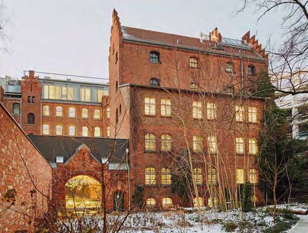
E 1.1 Hotel Wilmina in Berlin (DE) 2022, Grüntuch Ernst Architekten. The brick building was erected in Charlottenburg in 1896, served as a women’s prison, and later as a land registry.
E 1.2 completed housing in Germany according to age groups and share of brick residential buildings (percentages refer to total German existing building stock)
E 1.3 percentage of brick residential buildings according to age groups (percentages refer to buildings of the corresponding age group)
E 1.4 climate road map: distribution of carbon emissions up to 2045, three scenarios: a brick segment b lime-sandstone segment
upon both construction practice and society. In addition, romanticised views of masonry often obscure the fact that innovations have already been achieved. Contemporary masonry typically has very little in common with construction methods used 50 or 100 years ago. Current developments include methods based on the concept of bricklaying with units consisting of timber for interior walls and complete loadbearing structures, units consisting of EPS that find use as insulation or sacrificial formwork for concrete construction, or units made of recycled plastic. The durability, the modular assembly, and the potential for small-scale application offer opportunities for structured, systemic, and sustainable solutions in unitbased construction that apply the concept of bricklaying to other materials.
Masonry in an existing context
In the past centuries masonry construction –in particular using brick – has decisively defined building culture. Often it coincided with specific construction techniques, such as double-skin masonry walls with an air cavity as interstitial space, typical of northern Germany. Common between 1890 and 1945, this technique can be adapted to current energy standards by retrofitting with insulation fill.
Historical masonry construction possesses value that is worthy of preservation and further development. For the renovation of the Hotel Wilmina in Berlin, the carbon footprint, the volume of building waste, and the emissions generated by transporting construction materials were significantly reduced (Fig. E 1.1) [8].
Holocaust Museum
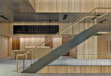
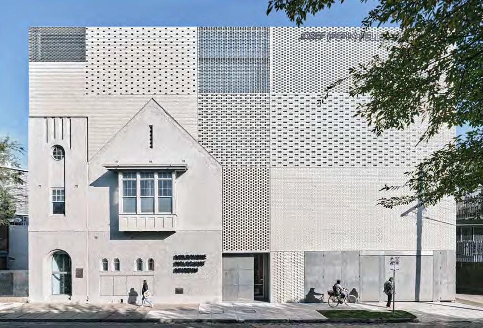
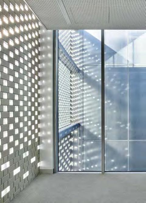
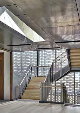
The museum was founded in 1984 by a private initiative and occupied the premises of a former pharmacy. The building, erected in the early 20th century, was extended in 1999. Due to the increased space requirements, it was not possible to carry out the museum’s latest restructuring within the existing building; only the original historical facade was preserved. To accommodate the significant expansion of the building’s volume and to address the Holocaust through architecture, the architect chose light as the central theme. The way light enters the building through the perforated facade is a symbol of learning and enlightenment. Depending on the particular function behind the facade, the type and scale of perforation are altered subtly and only recognisable upon taking a closer look. Brick and glass block are combined according to different masonry bonds and by adjusting their ratio. In terms of construction, they are connected by threaded rods and arranged within the facade in geometries resembling patchwork. Completely closed wall surfaces in cross bond border permeable walls with missing headers or cross bond with glass block as headers, bonds purely consisting of glass block, and perforated walls with glass block. The larger part of the loadbearing shell behind these facade skins consists of a steel frame, which allows light to pass through the perforated facing shells without further obstruction.
Melbourne (AU) 2022
Architecture
Kerstin Thompson Architects, Melbourne (AU)
Masonry type brick, glass block
Vertical section
Horizontal section scale 1:20
1 200/200/6 mm steel SHS
2 150/90/10 mm steel angle
3 230/110/76 mm glass block
4 230/110/76 mm brick
5 20 mm stainless steel threaded rod
6 20.5 mm (interior) /40.5 mm (exterior) silicone sleeve, translucent
7 200/200/12.5 mm steel SHS
8 LED lighting strip
9 roof construction: intensive greening
50 mm mulch layer
drip irrigation system ca. 1000 mm substrate layer geotextile
30 mm drainage element sealing layer screed, inclined separation layer
270 mm reinforced concrete ceiling
10 sliding door:
2 ≈ 4 mm laminated safety glass in aluminium frame
11 150/100/6 mm steel RHS
12 three-part sliding gate: 12.3 mm sheet aluminium, perforated, on steel frame
13 3 mm canted sheet aluminium ceiling panel
14 200/120/13 mm steel angle
15 floor construction:
600/300/20 mm granite pavers
10 –20 mm mortar bed
6 mm impact soundproofing mat reinforced concrete ceiling slab
Derek Swalwell
16 insulation glazing: 2 ≈ 6 mm laminated safety glass, metal mesh inlay + 12 mm cavity + 6 mm toughened glass in aluminium mullion-transom system
17 200/200/9 mm steel SHS column with 20 mm fire protection cladding
18 third floor wall construction: 230/110/76 mm masonry brick + 110/110/76 mm glass block + 80 mm cavity + 230/110/76 mm masonry brick + 110/110/76 mm glass block
19 first floor wall construction: 230/110/76 mm masonry brick 40 mm cavity breathable facade membrane 40 mm thermal insulation 200 mm prefabricated reinforced concrete element
92 mm metal studs inlaid mineral wool thermal insulation 13 mm gypsum board
20 insulation glazing: 2 ≈ 6 mm laminated safety glass, opaque, white enamel finish on back, metal mesh inlay + 12 mm cavity + 6 mm toughened glass, in aluminium mullion-transom system prefabricated reinforced concrete element metal stud framing 13 mm gypsum board
21 formwork block 190 mm concrete reinforcement 30 mm air space breathable facade membrane 92 mm metal stud framing inlaid mineral wool thermal insulation 13 mm gypsum board
22 existing building wall construction: exterior render min. 230 mm max. 350 mm masonry (existing) interior render
Imprint
Authors:
Ansgar Schulz
Univ.-Prof. Dipl.-Ing.
Benedikt Schulz
Univ.-Prof. Dipl.-Ing.
both:
Dresden University of Technology Faculty of Architecture
Chair of Architectural Design and Construction Schulz und Schulz Architekten GmbH, Leipzig
With professional contributions by: Prof. Dr.-Ing. Eberhard Möller
Karlsruhe University of Applied Sciences TWP Tragwerkplan GmbH
Prof. Dirk Bayer
RPTU Kaiserslautern-Landau bayer | uhrig Architekten PartGmbB
Prof. Andrea Uhrig
Koblenz University of Applied Sciences bayer | uhrig Architekten PartGmbB
M. A. Lotte Schlör
Dr.-Ing. Roland Göttig Technical University of Munich
Dr.-Ing. Lukas Lauss Technical University of Munich
Dipl.-Ing Eva Veres University of Stuttgart
Dipl.-Bauingenieur Christian Leis Kersken + Kirchner GmbH, Munich
Dipl.-Ing. Thilo A. Hoffmann Kersken + Kirchner GmbH, Munich
Prof. Dr.-Ing. Martin Zeumer RheinMain University of Applied Sciences
Dipl.-Ing. Matthias Hönig Schulz und Schulz Architekten GmbH, Leipzig
Editorial services:
Anne Schäfer-Hörr, Katja Pfeiffer (project managers) Jana Rackwitz (editorial services and layout, theory chapters), Jakob Schoof (editorial services, Parts D and E) Bastian Vollert (editorial services, project examples) Laura Traub (editorial assistant) Sandra Leitte (proofreading, German edition)
Drawings: Ralph Donhauser
Translation into English: Mark Kammerbauer, Landshut (DE)
Proofreading: Thomas Cullen, Olching (DE)
Cover design based on a concept by: Wiegand von Hartmann, Munich (DE)
Layout based on a concept by: muskat Kommunikationsdesign, Berlin (DE)
Production and DTP: Simone Soesters
Reproduction: ludwig:media, Zell am See (AT)
Printing and binding: Gutenberg Beuys Feindruckerei, Langenhagen (DE)
Paper: Materica Acqua (cover), Magno Volume (content)
© 2026, first edition German edition 2025 “Atlas Mauerwerk” (ISBN: 978-3-95553-670-1)
DETAIL Architecture GmbH, Munich (DE) detail.de books@detail.de
ISBN: 978-3-95553-684-8 (Print) ISBN: 978-3-95553-685-5 (E-Book)
This work is subject to copyright. All rights reserved. These rights specifically include the rights of translation, reprinting, and presentation, the reuse of illustrations and tables, broadcasting, reproduction on microfilm or on any other media and storage in data processing systems. Furthermore, these rights pertain to any and all parts of the material. Any reproduction of this work, whether in whole or in part, even in individual cases, is only permitted within the scope specified by the applicable copyright law. Any reproduction is subject to charges. Any infringement will be subject to the penalty clauses of copyright law.
This textbook uses terms applicable at the time of writing and is based on the current state of the art, to the best of the authors’ and editors’ knowledge and belief. All drawings in this book were made specifically by the publisher. No legal claims can be derived from the contents of this book.
Bibliographic information published by the German National Library. The German National Library lists this publication in the German National Bibliography (Deutsche Nationalbibliografie); detailed bibliographic data is available online at: http://dnb-nb.de