17 minute read
Sustainability

Vertical tolerances between beams and slabs Horizontal tolerances between columns and walls
± 20 mm ± 20 mm 1) or ± l / 600 max. 60 mm ± 25 mm
Advertisement
l = clearance 1) More stringent values may be required for columns and walls that support prefabricated parts, depending on the length tolerance of the supported component and the required bearing length.
Openings
15
cracked State II are much larger than those in the uncracked State I. Accurate estimates of deformation are difficult to make. Often the normative level of load is not achieved or the material exhibits greater stiffness than the standard predicts. Precise input parameters characterising the individual concrete-specific shrinkage and creep behaviour are also difficult to define for a given set of circumstances. Some scatter applies to these parameters, which means the designer has to rely on limit value considerations. The deformations for State I can be adopted as the lower limit value. The maximum expected deformations are calculated assuming State II. The prob able deformations will be somewhere between these two limit values. Fig. 17 shows that deformation f based on the input parameters load and the actual material resistances is subject to stochastic scatter and can also increase further during the service life due to shrinkage and creep. Deformation calculations are often based on engineering judgement. The normative load level is usually on the safe side in relation to the imposed load in service. To be able to accurately calculate deformations, the imposed load applied should be the one that most closely corresponds to the service load. This should be established in close consultation with the client. If in doubt, the bending members must be analysed in the cracked state under the critical load and the analysis must take into account the long-term effects of shrinkage and creep of the concrete, so that, even in this final situation, no strains are imposed on the secondary structural elements. The vertical loads of the facade itself, for example self-weight, fitting out, imposed service loads and their application points represent further input parameters for the calculations. Fig. 18 shows the recommended maximum allowable deformations in accordance with DIN EN 1992-1-1 [15].
DIN EN 1992-1-1 also offers the option of precambering the formwork by a maximum of l/250 to partially or completely compensate for the eventual sag. A max imum value for the deformation of f ≤ l/500 is recommended for the edges of slabs to which the timber panel construction elem ents forming the facade are connected. Deformation calculations for the uncracked State I can be performed using the theory of elasticity. Analyses for the cracked State II are increasingly performed using modern structural engineering software solutions. The increasing variety of numerical modelling techniques available means it is relatively simple to calculate deformations in the cracked State II using the finite element method (FEM). The calculations are routinely carried out for conventional concrete structures and hybrid construction. In order to arrive at reliable deformation tolerances for the reinforced concrete structure, the designer must focus particularly on State II. The results of the calculation must be verified by the structural engineer for the project.
Parametric Study
A parametric study [16] that was carried out as an aid to the designer evaluates the edge deformation of a slab span. This allows the designer to make a preliminary assessment of whether a proposed column or wall grid will result in acceptable
14 Definition of the dimensions of timber panel construction elements 15 Building shell tolerances in accordance with
DIN EN 13 670 16 Limit deviations for walls in accordance with
DIN 18 202-3 17 Probability of the calculated value of the deformation f shown in relation to time t 18 Recommended maximum allowable deformations in accordance with DIN EN 1992-1-1
Design dimensions [m] Limit deviations [mm]
Deformation [f] Upper limit value Likely value Lower limit value (State I) (pure State II)
Width, height (edge length), opening Up to 1.00 m± 2 mm
Over 1.00 m± 0.2 % of the design dimension maximum ± 5 mm t = 0
Determining factor
Consideration of appearance and serviceability for slabs and beams
Damage of adjacent components caused by deformations
Maximum sag
l /250
l /500
7a b
Hybrid construction makes a positive contribution to summer thermal insulation in several ways. The relatively low thermal transmittance of the timber frame construction elements due to the required winter thermal insulation effectively attenuates the amplitude of the temperature difference cycles between the internal and external sides of the building component. In spite of large day-night fluctuations of surface temperature on the outside of the building of almost 20 kelvin, the corresponding fluctuation of surface temperatures inside the building is less than 1 kelvin. The reinforced concrete structure, which acts as a large thermal store, has a positive effect on the summer thermal insulation and the analyses take appropriate account of this effect in accordance with the relevant standards.
Moisture Protection
It is essential that moisture is continually conducted out of buildings or prevented from occurring in the first place. Building users risk harm and the building construction considerable damage from the unplanned occurrence and uncontrolled effects of moisture. Possible negative consequences include damage to the building fabric, a less effective thermal building envelope or a reduced quality of indoor climate, which may even cause users to become ill (e.g. mould, sick building syndrome). Protection against moisture should therefore be given careful consideration during design and construction.
Mould Formation
Preventing moisture from occurring on the indoor surfaces of the components of the thermal building envelope is the main way of protecting against mould formation. The crucial factors here are the relative humidity and temperatures near and on the surface of the building component. DIN 4108-2 gives appropriate minimum insulation requirements for thermally effective building components. In the case of hybrid construction, the high standard of insulation of the panels excludes the possibility of mould formation. The temperatures on the inner surfaces of the components are normally only a few tenths of a degree below room temperature, which raises the relative humidity of the nearby air by only an insignificant amount compared to the average indoor relative humidity. In the area of thermal bridges caused by connections to the reinforced concrete structure, the designer should take into account the information given in the section on “Thermal insulation” (p. 33ff.).
Condensation
The formation of condensation within the external building components must be avoided or at least limited as much as possible. In general, the stored quantity of water arising from condensation in the component during the dew period (December to February) should be limited to 1.0 kg/m2 or 0.5 kg/m2 on and in vapour barrier layers. With timber frame construction, it is also important to limit the change of moisture content of each material, such as wood (+5 % by mass) and wood-based materials (+3 % by mass). The possible quantity of condensate can be estimated using the Glaser method in accordance with DIN 4108-3. It should also be checked whether the condensation formed can evaporate over the evaporation period (June to August).
Airtightness
In addition to the external walls having the correct vapour diffusion properties, particular attention must to be paid to the airtightness of the building. Otherwise thermal or moisture leaks can occur. Leaks due to lack of airtightness give rise to slow-moving currents of air (convection) through the construction. On its way to the open air, the warm building air cools in the building component to the extent that water condenses there. The moisture quantities entering building components through this convection effect are difficult to determine in practice. They are taken into account in hygrothermic calculations, e.g. in accordance with EN 15 026, as an annual add itional quantity of moisture in the component of e.g. 250 g/m2a. Advice for the design of the timber frame construction element facade: • For vapour diffusion tightness, the maxim is: as open as possible, as tight as necessary! More vapour-permeable layers on the interior side allow the panel construction walls to dry out in summer and make the construction more robust against moisture (paper instead of plastic bags) • The vapour-retarding airtightness layer should run on the interior side of the core element behind the service cavity. • The external cladding of the core element should be as vapour-permeable as possible. • There should be an external windtight layer to act as a second practically airtight layer to prevent convection flows (see “Air and Windtightness”, p. 37ff.) • The component layers on the interior side should be much more diffusion- retardant (by about five to ten times) than the outer component layers. • Mineral plasters are recommended for use with ETICS
Externally, the facade must withstand the effects of driving rain. Requirements for the materials used to provide this weather protection are specified according to the exposure groups in DIN 4108-3. In
Airtightness layer Airtightness layer
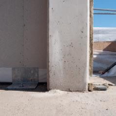
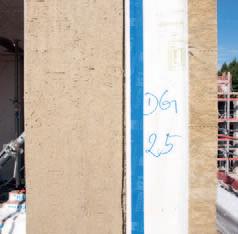
7 Reinforced concrete column a Bottom of a reinforced concrete column before installation of the external wall b Front view of the reinforced concrete column including a layer of insulation, on the right: the cross section of a self-supporting timber panel construction element set forward of the concrete structure 8 Arrangement of the airtightness layer a For self-supporting timber panel construction elements b For inserted timber panel construction elements 8 a b
hybrid construction, rear-ventilated timber facades or ETICS with water-repellent plasters can be designed to meet even the highest of these requirements. A second water-directing layer should always be provided on the outside to improve robustness against moisture.
Air and Windtightness
In order for the building envelope to maintain the effectiveness of its building- physical properties, it must be constructed to be air and windtight (see “Moisture Protection”, p. 36f.). Adequate airtightness prevents air flowing through building components as a result of air pressure differences between inside and outside the building (wind currents, ventilation systems). The windtightness of the outer surface of the building is intended in particular to prevent air from flowing through the thermal insulation due to wind exposure. It is also a second means of ensuring airtightness. Defects in the air and windtightness layers of a building often lead to adverse effects on the protection of its construction against moisture, heat, sound and fire [6]. The design and installation of the air and windtightness layers should be in accordance with the requirements and recommendations of DIN 4108-7, which contains additional prac tical examples for overlaps, connections and penetrations for various parts of the building construction. The special challenge in hybrid construction is the proper design and construction of connections and the surrounding areas, taking into account the different tolerances for reinforced concrete and timber construction. In particular, the prefabrication of the timber frame construction elements requires careful detailing (see “External Wall Joints”, p. 49ff.). However, the high quality of the panels brings the significant advantage of far fewer leakages than are typically found in other types of buildings. Designers should observe the following guidance for the building envelope to ensure adequate air and windtightness: • Airtightness must be achieved by at least one layer. Combining several inadequate airtightness layers does not guarantee adequate airtightness [7]. • The airtightness layers of the building envelope must continuously enclose the building interior, i.e. they must have no breaks or interruptions. The various parts of each airtightness layer must form a completely bonded whole [8]. • The cladding on the interior side of the core elements is particularly suitable for ensuring airtightness in timber frame construction elements. The external windtight layer provides the secondary level of protection against leaks. • As is the case with vapour diffusion, the maxim “inside tighter than outside” applies. With airtightness, however, it should always also be “as tight as possible”. • In the case of self-supporting timber frame construction elements set in front of the load-bearing structure, the airtightness layer of the building envelope, e.g. OSB boards attached by adhesive, continues across the end of the floor slab (Fig. 8 a). In addition, the airtightness between the building’s usage units is guaranteed by extra glued-on components on both sides (smoke exclusion, sound and odour protection). • Air or windtight layers usually perform two functions. Depending on their pos ition in the component, they can also be the second water-directing layer, a breathable or vapour diffusion- tight layer. • In the case of inserted timber panel construction elements, the airtightness layer with film must be run around the
intruding reinforced concrete components (Fig. 8 b). • The plaster acts as the windtightness layer where an ETICS is used. • For rear-ventilated facades, the outside cladding of the core element must provide windtightness or be supplemented by a suitable breathable film.
Fire Protection
Since the effectiveness of a building’s fire protection is proven only in the extraordinary situation of a fire, it may be years before undetected poor-quality construction results in catastrophic consequences. Focused and diligent design and construction is therefore essential. The objective of an effective fire protection concept is to prevent a fire from occurring, to contain fire and smoke in the event of a fire, to allow self-rescue, the evacuation of others and effective fire extinguishing [9]. In addition to structural stability, fire protection is one of the important requirements in eliminating acute risks to life and limb.
Legal Requirements
Laws and regulations have much to say on the fire protection for buildings. In Germany, the legislation governing the design of fire protection for buildings is continually changing. The legal framework described below is based on the situation in 2019. Furthermore, the approach of the German design rules for fire protection is profoundly different to that in other European countries, though the standards they aim to achieve are comparable. The German Model Building Code (MBO) sets out all the general requirements for building construction and their principal aim of achieving the protection goals [10]. In contrast to other protection goals, those for fire protection
Floor Slab Joint, Self-supporting External Wall Elements; With Services Cavity
Vertical load is transferred by contact pressure between the two wall elements. The steel angle connects the wall elements to the reinforced concrete slab and supports them in the horizontal plane. The maximum deformation of the reinforced concrete slab must be ≤ 10 mm. The wall elements are protected from deformation by the vertical elongated holes and the spacer sleeves used with the connecting wood screws. The floor construction should be free of services.
4.
5.
2. 11.
8.
1. 6.
6. 9.
10. 3.
7. 8.
Installation and Joint Construction
1. Fasten the steel angle to the reinforced concrete floor slab 2. Fix the insulation strip in accordance with EN 13162 (melting point > 1,000°C) onto the front edge of the reinforced concrete slab shortly before installing the external wall 3. Install the external wall element on the lower floor including the render carrier board 4. Install the external wall element on the upper floor including the render carrier board 5. Inspect the butt joint on site for flushness and rectify if and where necessary 6. Ensure air and smoketightness (top and bottom), e.g. with selfadhesive tape 7. Apply ceiling plaster or fill voids at the
reinforced concrete slab/wall corners 8. Construct the services cavity (here using horizontal laths) 9. Seal continuously the gypsum plasterboard type DF (GKF) joints at the wall, ceiling and floor to improve sound insulation in accordance with
EN 15651-1 10. Apply render 11. Install floor construction
Vertical section Scale 1:10
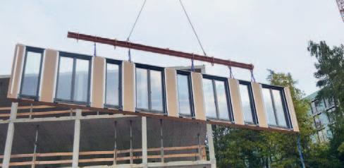
1 Timber panel construction element:
Thermal insulation composite system (with approval for construction use) consisting of 8 mm plaster 60 mm fibre insulation board (WLS 045) 16 mm MDF board (medium density fibreboard, windtight layer) vapour-permeable 160 mm solid structural timber (KVH) (a = 62.5 cm stud spacing), thermal insulation filling (WLS 040) 15 mm OSB board (airtight layer) 60 mm services cavity with structural timber (KVH) subconstruction (a = 62.5 cm stud spacing), thermal insulation filling (WLS 040) 2≈ 12.5 mm gypsum plasterboard type DF (GKF) 2 Floor construction: 12 mm floor covering 70 mm cement screed 0.2 mm PE film separating layer 30 mm impact sound insulation (WLS 045) 40 mm thermal insulation (WLS 040) 260 mm reinforced concrete slab with 30 mm insulation strips at the front edge 10 mm plaster 3 Force-transmitting joint between top and bottom rails 4 2≈ 2 wood screws (e.g. full thread screw (VGS) 8.0 ≈ 140 mm) with spacer sleeves and elongated holes 5 Concrete anchor bolt /screws with plain washer (e.g. M 12) 6 Steel angle (e.g. L150/200/12 mm, S 235) 7 Glued membrane (air and smoketightness) 8 Flexible joint seal 9 Flush butt joint of the fibre insulation boards 1
3 9 4
4 5 6 7 2
8 7
Sound Insulation Thermal Insulation and Moisture Protection Fire Protection
Dn, f, w (C; Ctr) = 65 (-2; -7) dB
Wall element: RW (C; Ctr) = 45 (-1; -6) dB (applies to the depicted wall construction in accordance with DIN 4109-33, Table 6, line 6)
Reinforced concrete slab: RW = 67 dB Ln, w = 37 dB Sound insulation values of the floor slab do not take into account flanking sound transmission. They apply to the depicted construction, 260 mm thick, floating screed with m' ≥ 140 kg/m2 and impact sound insulation board with s' ≤ 20 MN/m3 (in accordance with DIN 4109-2, DIN 4109-32 and DIN 4109-34).
Uwall element = 0.15 W/m2K
Ensuring the laths in the services cavity are positioned at a distance from the reinforced concrete slab reduces thermal bridging. The height of the bottom and top rails should be kept to the minimum required for structural purposes to reduce potential thermal bridging. So that the wall construction complies with the requirements for building classes 4 and 5, the core elem ent must have a fire-resistance rating of 30 minutes (EI 30). In Germany, verification of usability must be provided for the core element construction (e.g. DIN 4102-2). In addition, the materials in the facades for building class 4 and 5 must limit the spread of fire, therefore the facade system must comply with the German reaction to fire classification of “flame- retardant” (A1, A2 or B1 in accordance with the German classification system). These arrangements effectively suppress fire spread across the facade. The design must also consider secondary fire paths in the area of the joint.

Example Projects
70 “Aktivhaus” – Multistorey Apartment Building in Frankfurt am Main HHS Planer + Architekten, Kassel
76 Experimental Residential Buildings in Wuppertal-Ostersiepen ACMS Architekten, Wuppertal
82 “Ecoleben” – Multistorey Residential Buildings in Penzberg Lang Hugger Rampp Architekten, Munich and Krämmel Bauplan, Wolfratshausen
86 35 New Subsidised Housing Units in Freising A2freising architekten + stadtplaner, Kai Krömer and Stefan Lautner, Freising
Vertical section element butt joint Horizontal section floor slab Scale 1:5
1 Timber panel construction element: 8 mm composite resin board rear-ventilated, joint backing 40 mm top-hat profile aluminium subconstruction 16 mm wood fibreboard, vapour-permeable, water-repellent tongue and groove Z joist: Verticals: 65/65 mm squared timber, 18 mm OSB board web, 65/65 mm squared timber, with 260 mm stone wool thermal insulation fill 18 mm OSB board, butt joint glued airtight 2 2 mm aluminium sheet anodised 3 Element butt joint 4 Element joint gap subsequently tightly filled with mineral thermal insulation (WLG 035) 16 mm wood fibreboard cover, vapour- permeable, water-repellent, movement connection at bottom
Gap windtight self-adhesive seal, vapour-permeable Precompressed sealing tape 5 Gap allowing movement 6 French window triple-glazed, laminated wood frame 7 Skirting timber, grey varnished 2 mm sound insulation strips 8 Window self-adhesive seal, airtight, vapour-retardant 9 Facade anchor bolt sealing layer 12 mm facade anchor bolt galvanised steel, grout filling 10 Mineral wool insulation strips in front of slab edge, compressible
Rear filling around the anchor with force- transmitting attachment to concrete slab to prevent slipping 11 Sealing layer, airtight, vapour-retardant, with fold to accept slab deflections of up to 15 mm
Timber cover strip between facade / slab allowing movement 12 Floor construction top floor: 8 mm mosaic parquet, oak 50 mm cement screed Separating layer PE sheeting 20 mm impact sound insulation EPS 220 mm reinforced concrete slab 5 –10 mm plaster 13 Element connection oak: 16 mm wood fibreboard, vapour-permeable, water-repellent, tongue and groove, butt joints glued windtight Voids plugged with mineral wool (WLG 035) 14 Corner profile: system profile glued behind facade boards 15 Joint with mineral wool (WLG 035), hydrophobic, highly compressible 16 12.5 mm gypsum plasterboard, butt joints filled 17 2≈ 12.5 mm plasterboard 240/240 mm reinforced concrete column 18 Electrical services shaft 2
3
4 5
5 6
7 8 9 10 12
11
