We appreciate your feedback. Send it to segments@delveunderground.com
Managing Editor Allison Halvorson, CPSM
Contributing Editors Mary Brownell, Lucy Campos, Audrey Rivero
Graphic Designer Seth McGinnis
Executive Editor Victor Romero, PE, CPEng, CEG, ENV SP
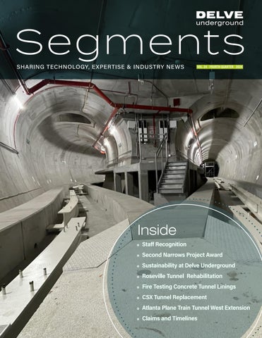
Cover image: Atlanta Plane Train Tunnel West Extension
Staff Recognition
Congratulations to the following staff members who have achieved significant career milestones.
Jacob Facey, PE ; Leigh Anne Zhang, PE; Dingxin Cai, PE; and Nikhil Mishra, PE , earned their Professional Engineer licenses.
Ambili Chalippat Valsan, CPEng; and Daniel Rodrigues, CPEng, achieved Chartered status through Engineers Australia.
Fred Marquis, PE, PEng, LEED AP, presented (with Charlton Mosdier, PEng, Pomerleau-Bessac General Partnership) a Case Study on the Installation of Shaft Permanent Lining Using Slipforming Techniques at the Annacis Island Wastewater Treatment Plant New Outfall Project at the Tunnelling Association of Canada 2024 Conference in Montreal.
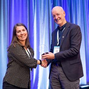
Stephanie Robillard, MASc, PEng, received a service award from the Tunnelling Association of Canada (TAC) in recognition of her contributions as Regional Director for British Columbia on the TAC Board of Directors from 2018 to 2023.
F. Marquis
Valsan
Facey Zhang Cai Mishra
Rodrigues
Second Narrows Wins Project Award
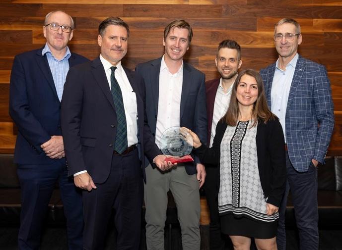
The Second Narrows Water Supply Tunnel Project was presented the Tunnelling Association of Canada’s Canadian Project of the Year – Under $300 Million Award for 2024. Delve Underground served as the Design Lead for this Metro Vancouver project, working with a great team to design and construct the tunnel. The Second Narrows Water Supply Tunnel will help deliver high-quality drinking water at an increased capacity, even after earthquakes. Congratulations to the Delve Underground team members who worked on this project, including those pictured (left to right) Charles Hunt, Andrew McGlenn, Greg Emslie, Fred Marquis, Stephanie Robillard, and Doug Grimes.
Sustainability at Delve Underground
“Sustainability is a part of how we operate our business, and not just part of our projects when our clients request it.”
Victor Romero President/CEO, Delve Underground
Watch a video featuring Delve Underground President/CEO Victor Romero outlining the sustainable practices the firm is implementing in tunnel and underground projects, and how these efforts align with our clients’ sustainability goals for design, construction, and operation.
CLICK TO WATCH!
Victor Romero President/CEO
Rehabilitation Historic Roseville Tunnel
Providing New Rail Service in New Jersey of the
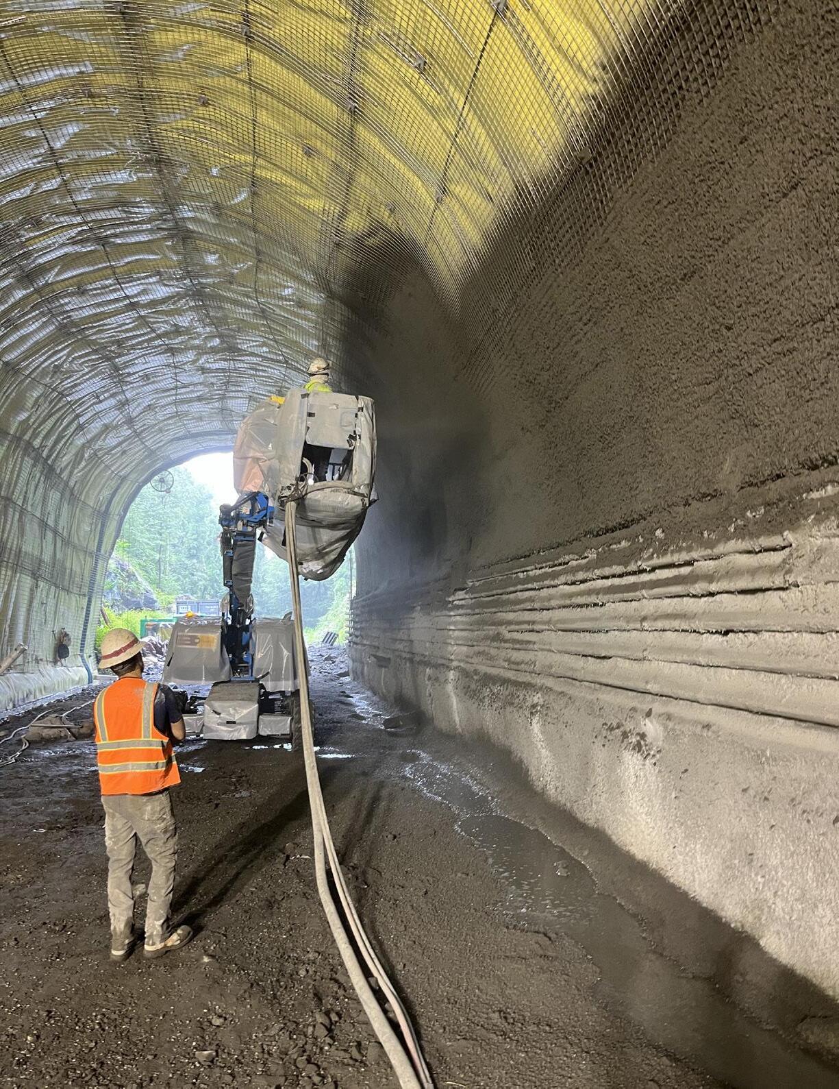
Application of shotcrete final liner over the PVC waterproofing membrane
by Daniel Ebin, PE, DBIA
About an hour northwest of Newark, New Jersey, is the historic Roseville Tunnel, situated in Byram Township, Sussex County. The Roseville Tunnel Rehabilitation Project is a design-build project and is part of NJ TRANSIT’s (NJT) Lackawanna Cut-off Restoration. The Lackawanna Cut-off—a historic rail line in New Jersey and Pennsylvania—was originally built by the Delaware, Lackawanna & Western Railroad in the early 1900s. It runs from Port Morris Junction in New Jersey to Slateford, Pennsylvania. NJT’s restoration will extend passenger rail service from Port Morris, New Jersey, to a new rail station in Andover, New Jersey.
The horseshoe-shaped Roseville Tunnel was completed in 1911. This rock tunnel was originally double-tracked and operated for freight and passenger transport from 1911 to 1979. It is mostly unlined, but has approximately 140 feet of concrete liner where a regional fault runs through the tunnel.
The design-build team is led by Schiavone Construction Company LLC, and Delve Underground is the lead designer. Eight specialized subconsultants are also on the design team.
Notice to Proceed was received from NJT in September 2022. Delve Underground designed the rock excavation, slope protection, concrete repairs, tunnel linings, and waterproofing, as well as managed the design team and the design services during construction. The design team had 180 calendar days to prepare the 60% design documents and 325 days to prepare the 100% design documents.
PROJECT MILESTONES
January 2023
July 2023
Construction mobilization and site clearing.
Rock slope and tunnel scaling began, followed by slope protection installation and rock dowels in the tunnel.
October 2023
August 2024
2024–2025: Final construction elements
Installation of the initial shotcrete liner in the tunnel began, followed by installation of the waterproofing membrane and repairs to the existing concrete liner.
Final shotcrete liner installation started and is currently ongoing, will be closely followed by drainpipe installation and ditch restoration.
Installation of the emergency walkway, electrical and communications systems, and new ballast.
The scope of work for the project
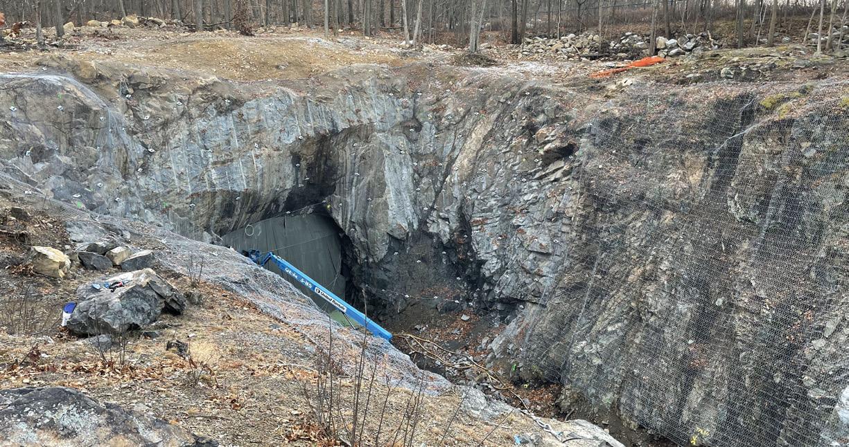
} Rock excavation by blasting at the west portal of the tunnel to shorten it by at least 15 feet, from 1,014 feet to just under 1,000 feet long.
} Slope protection and stabilization on both the west and east rock cut approaches to the tunnel, including removal of loose rock, vegetation and tree removal, installation of cable mesh and netting, rock bolting, and construction of adequate catchment areas at the base of the slopes.
} Repair of the existing concrete tunnel liner, which includes grouting the void space behind it and repairing surface defects and concrete spalls.
} Removal of loose rock and rock bolting in the unlined sections of the tunnel.
} Installation of a shotcrete initial lining in the unlined sections.
} Installation of a PVC waterproofing membrane to provide a continuous tunnel waterproofing system through the tunnel.
} Installation of a shotcrete final lining throughout the entire tunnel.
} Installation of CCTV cameras at both portals.
} Installation of communications systems in the tunnel and a communications tower above the tunnel to receive radio signals.
} Installation of a lighted path inside the tunnel for employee and first responder access and evacuation purposes, extending 50 feet beyond both portals.
} Installation of permanent electrical power to the tunnel.
} Restoration of 8,000 feet of track roadbed to 3 inches below the bottom of existing ties, including cutting, clearing, and disposal of all brush, trees, vegetative matter, and debris; roadbed excavation; restoring the drainage system; and initial ballast placement.
} Obtaining selected permits required for construction.
Rock slope protection and stabilization underway at the West Portal
Uncovering the Real Purpose of Fire Testing in Concrete Tunnel Linings
If you’re not familiar with fire design of concrete tunnel linings, you might assume that fire tests are conducted to validate that the lining has adequate strength capacity for a specified fire load (e.g., hydrocarbon or Rijkswaterstaat [RWS] curves). However, in most tests, this is not the case—at least not directly.
Fire tests are performed for two main reasons
To validate that the thermally affected parameters assumed and resultant thermal gradients through the concrete lining reflect the values used in the design. From our experience, having witnessed numerous fire tests, we’ve found that the thermal behavior and the associated thermal affected parameters (e.g., reduction in strength and stiffness) of concrete linings tend to align well with the recommended values provided in Eurocode 1 and 2 (EN 1991-1-2, EN 1992-1-2). Thus, for typical tunnel lining concrete mixes, the fire test samples generally pass this performance requirement.
To validate the assumed spalling behavior of the concrete material, in particular, “explosive” spalling, which is known to occur in concrete under certain conditions. Unlike the thermal behavior (see above), spalling performance can vary considerably based on the mix design. Accurately estimating likelihood and, most importantly, the depth and extent of explosive spalling via engineering numerical models is not possible under the time frames typically given to designers. We typically rely on previous experience (published data) to determine a reasonable spall depth to be used in our designs. Explosive spalling, for this discussion, is generally defined as spalling that occurs early in the design fire (first couple of minutes). It is typically observed in tests with hydrocarbon (HC) design fire (or similar) that have a very rapid initial temperature increase with time. Thus, in our experience, the main reason to perform fire testing is to validate the spall depth assumption for the adopted mix design.
by Mark Trim BE (Civil), MSc (Mining), CPEng, RPEV, RPEQ, PE
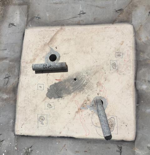
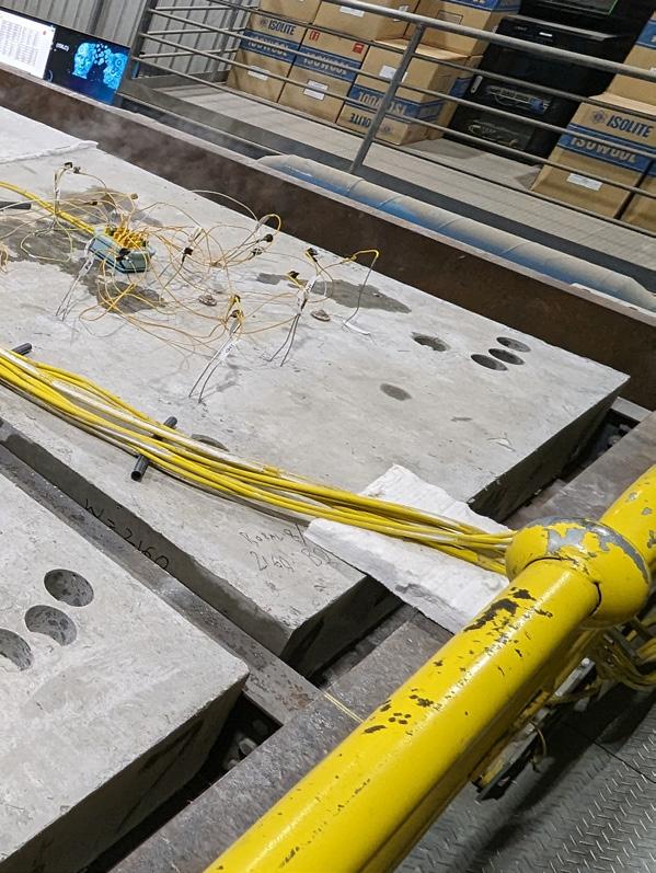
Post-fire test sample showing limits of the spalling and cores taken for material testing
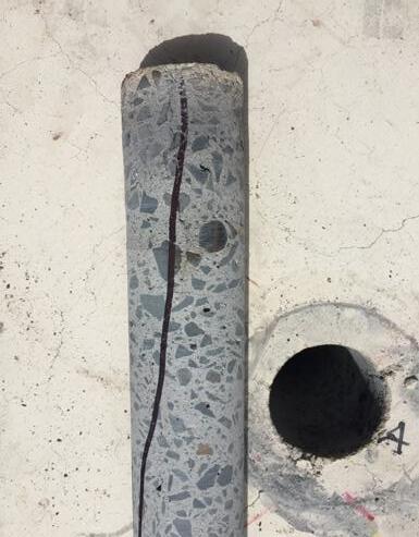
Post-fire cores taken for material testing
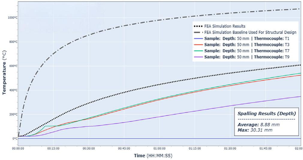
FEA Simulation Results
FEA Simulation Baseline Used for Structural Design
Sample: Depth: 50mm | Thermocouple: T1
Sample: Depth: 50mm | Thermocouple: T3
Sample: Depth: 50mm | Thermocouple: T7
Sample: Depth: 50mm | Thermocouple: T9
Spalling Results (Depth)
Average: 8.88 mm
Max: 30.31 mm
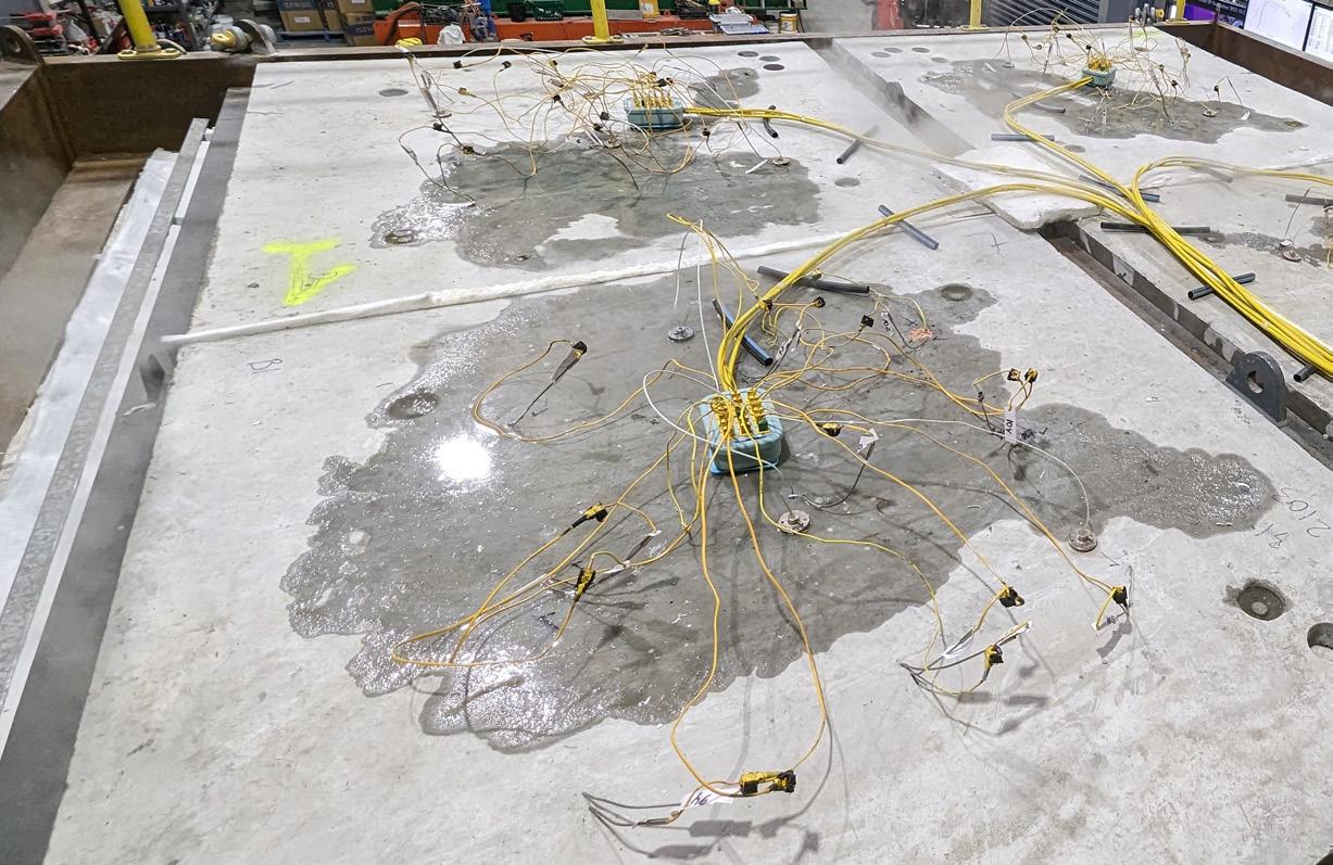
Fire test result example: Segmental lining 2-hr hydrocarbon–modified fire exposure test (via EFNARC) data at 50 mm cover with spalling measured – SFRC mix design with 1.5 kg/m3 polypropylene fibers. Note conservatism between structural design thermal profile and measured concrete thermal response (and post-fire test FEA back analysis)
Why Full-Scale Fire Testing Isn’t Always Necessary
With current commercially available structural numerical analysis software (e.g., Strand7, SAP2000, etc.) and computing power, engineers can assess the likely performance of tunnel linings during (and/ or post) a specified design fire. Full-scale testing of tunnel linings is generally not warranted. Fire testing is needed for design fires with high thermal energy outputs (HC, HC-Mod, RWS, etc.) to verify concrete mix design spall risk assumptions. However, the testing should be viewed as another material test (e.g., like compressive strength) rather than a test that specifically validates the structural design of the tunnel itself. There will be certain situations that may require full-scale fire testing, but these are situations where extreme fire scenarios are expected, or structural failure consequences are catastrophic. Otherwise, fire testing, generally in accordance with EFNARC 2006, will be adequate for most underground structures.
Top view of test samples (4 samples) taken during testing
Replacing an Old Bridge with a New Tunnel Using Corrugated Structural Metal Plate
by Kenneth Leo Dombroski, PE, MPA
The current economy, characterized by high inflation and a degree of uncertainty, has brought on a reality for public agencies and other infrastructure owners that there is a need to do more with less. This extends to areas of maintaining, rehabilitating, replacing, or expanding their assets. Savvy infrastructure managers are always looking for ways to salvage existing facilities while making upgrades.
This article examines how CSX Corporation (CSX) salvaged its existing bridge under circumstances that needed creative solutions. The bridge project had non-negotiables, including site access constraints and the inability to shut down rail service, except for one 24-hour period. CSX chose corrugated
structural metal plate (CSMP) because of its adaptability to overcome these difficulties.
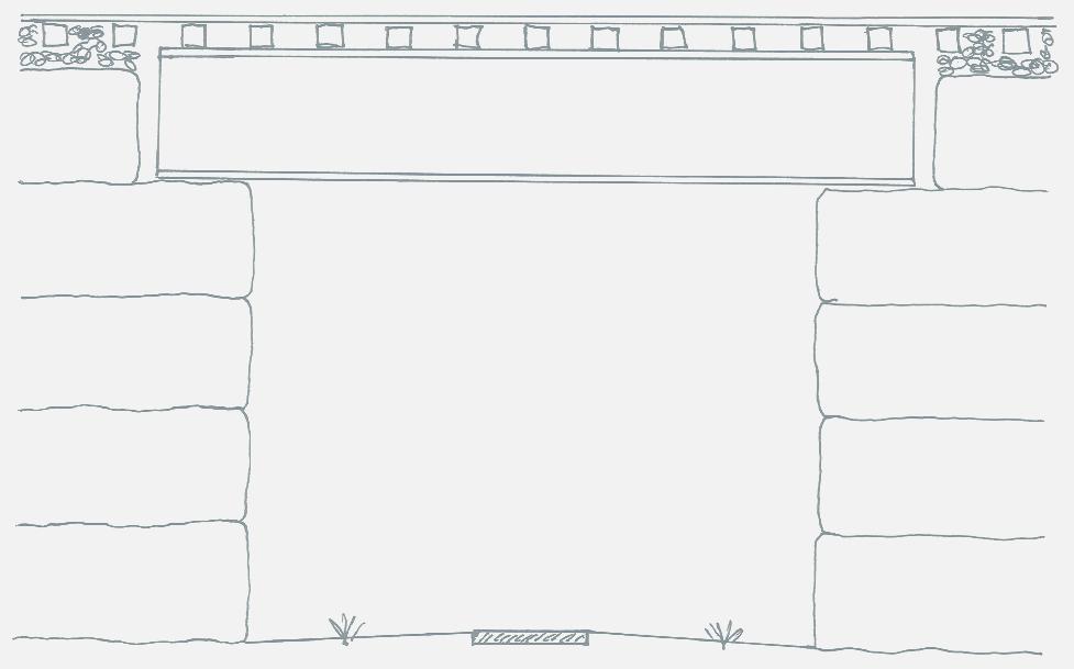
CSX owns and operates parallel railroad tracks that run east to west through Newton Falls, Ohio. They are part of a critical freight route between the East Coast and the Midwest. The Newton Falls portion includes structure BG95.6 over the city’s pedestrian and fitness trail connecting the north and south sides of the community. The original structure over this trail was a steel girder bridge on sandstone abutments, originally constructed in 1904. The steel girders from the original installation were well beyond their prescribed service life and needed to be replaced to protect the sensitive nature of this critical freight route.
Existing bridge conditions before replacement with tunnel
DRAWING NOT TO SCALE
Steel girders from 1904
Wood ties (typ)
Rail tracks
Ballast
30′± face of walls
Pedestrian and fitness trail
Sandstone abutment from 1904
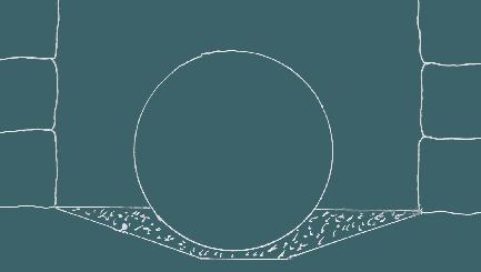
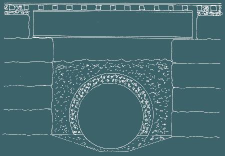
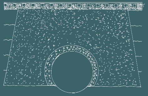
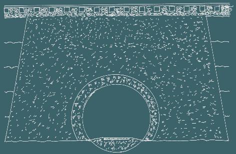
The construction of the new tunnel by CSX crews was completed in four phases.
Removal of existing walk, preparing a crushed stone aggregate base foundation
Assembly in place of galvanized steel corrugated structural plate forming a circular tunnel shell
Construction of the concrete slope collar at tunnel portals
Installation of crushed stone backfill in compacted 6-inch lifts to within 5 to 6 feet of lower flange of existing girders
Removal of steel girders, ballast, wood ties, and track rail to allow for completing backfill to appropriate grade
Placement of new ballast, ties, and rail
Steps 3e and 3f completed in one 24-hour weekend period
Sandstone abutment walls left in place and buried in stone backfill
Long-duration shutdowns were not an option on this segment of the parallel east-west track because of CSX’s commitments to its freight customers. Also, an important constraint associated with replacement-in-kind of the girders is the residential neighborhood immediately next to the bridge, which limited the ability to mobilize large equipment such as cranes onto the bridge site. Another important consideration was CSX’s desire to implement a solution that would allow its own maintenance crews to build the replacement structure. Finally, CSX was seeking a solution that reduces maintenance costs over the service life of the new structure.
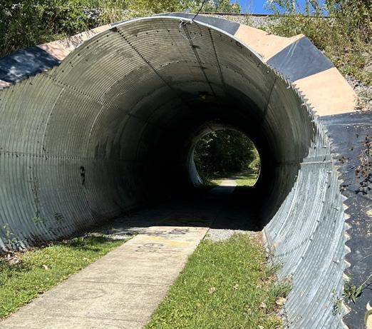
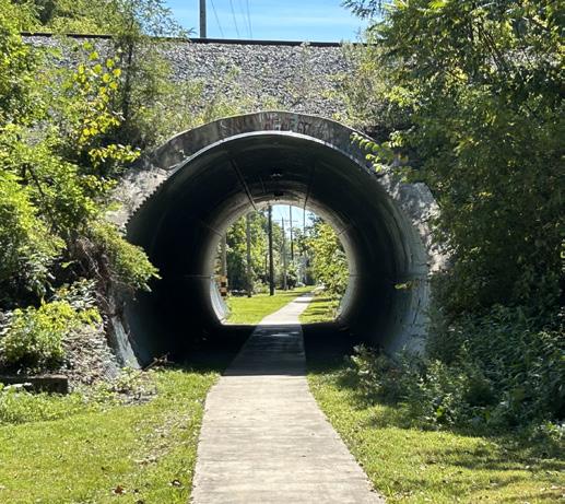
All these factors led CSX to determine that building a 140-foot-long tunnel using CSMP was the best option to accomplish the replacement of the bridge. The specific material chosen by CSX consisted of galvanized steel corrugated structural steel plate due to its ability to provide a minimum service life of 50 years and a manufacturing lead time of only 2 weeks.
By replacing a bridge with a soil-structure interaction system with CSMP to create
a tunnel, CSX was able to implement a cost-effective solution that addressed the constraints associated with both its rail operations and the site location. The tunnel will also be less expensive to maintain over the 50-year minimum service life compared to a bridge. Furthermore, the railroad operator will have little concern about track settlement over the tunnel. The existing sandstone abutments and concrete collars at the tunnel portals will confine the compacted, well-graded stone backfill around the CSMP tunnel shell to prevent ground loss. Most importantly, CSX was able to accomplish this infrastructure upgrade using its own crews while limiting the track shutdown to 24 hours.
This example of CSX’s creativity provides inspiration to other infrastructure managers to consider replacing their aging bridges with a tunnel!
(Note from the Author: The tunnel described in this article was constructed by CSX in 2012. The designer and engineer of record is CONTECH Engineered Solutions. CONTECH also manufactured and supplied the galvanized steel structural plate for the project.)
South tunnel portal
North tunnel portal
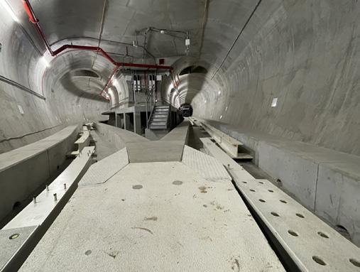
Atlanta Plane Train Tunnel West Extension
At the Hartsfield–Jackson Atlanta International Airport, the automated people mover system was extended and the terminal was renovated at the baggage claim station as part of the Atlanta Plane Train Tunnel West Extension (PTTWE) progressive design-build project. The City of Atlanta is the project owner, and Delve Underground is the lead designer for the Clark/Atkinson/Technique design-build joint venture.
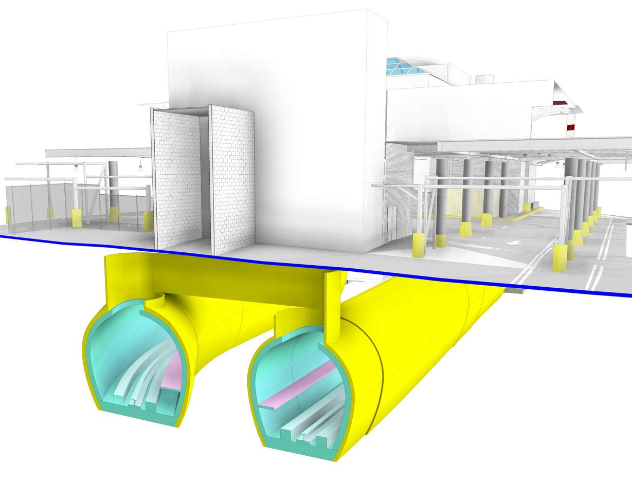
The project added a switch and tail track west of the current western end of the Plane Train system to enable a reduced headway and to increase capacity for future ridership. The existing tunnels have been extended westward about 660 feet to a 30-foot-diameter construction
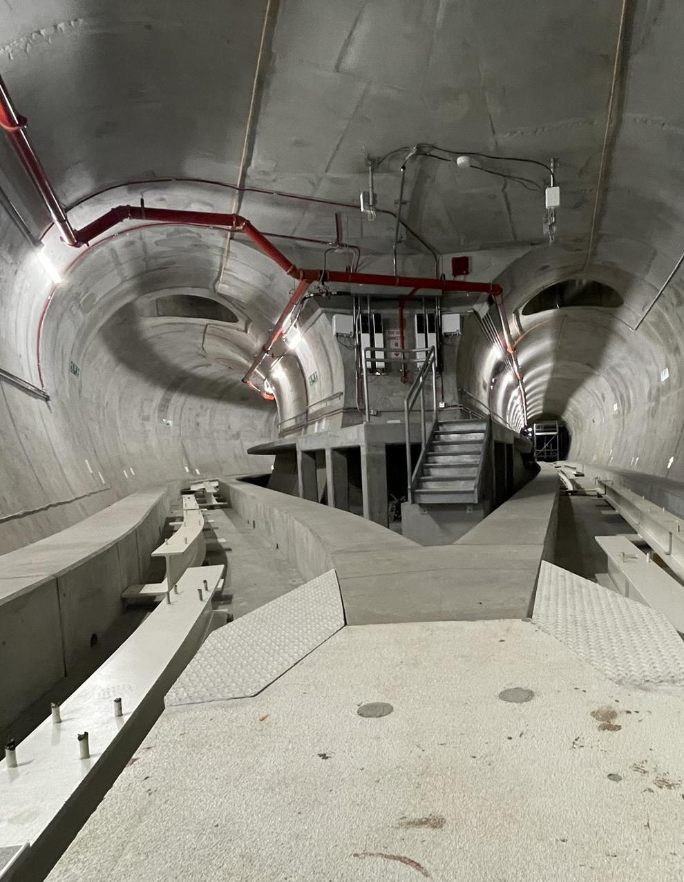
Finished (structural) tunnel bifurcation
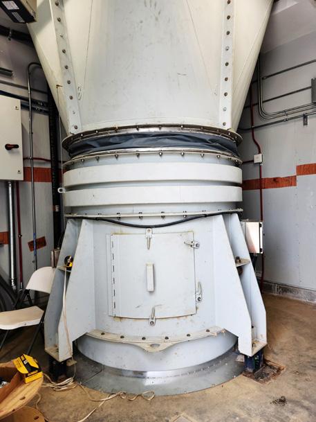
and emergency egress shaft. Approximately 408 feet east of this shaft connection, a twin tube bifurcation was constructed, and the tunnel divides into a north tunnel and a south tunnel to connect to the existing automated people mover mainline tunnels. The typical tunnel section is horseshoe-shaped with finished dimensions of approximately 12 feet wide at springline and 17.5 feet tall. The finished dimensions of the bifurcation include a span up to 40 feet wide and a height of 17.5 feet with up to 25 feet of flat roof in the span’s middle. The project included the design and construction of a ventilation system for the tunnel extension, which involved the construction of a ventilation pathway at the egress shaft, a cut-and-cover ventilation tunnel, and a utility building housing two new 120 kilo-cubic feet per minute (kcfm) fans.
by John Murray, PE, and Daniel Ebin, PE, DBIA
Ventilation
Newcomb & Boyd and Stacey Agnew provided ventilation design as subconsultants to Delve Underground. The ventilation in the existing Plane Train system used fans at the ends of the tunnels and in the middle of the tunnels for supply and exhaust based on the desired airflow direction. This allows the system to be operated in discrete ventilation zones to respond to fires. With this configuration, the ventilation for the West Extension could be designed such that there are no performance or operational changes to the existing system.
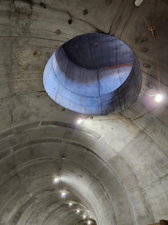
The flexibility of the progressive design-build model allowed the team to develop alternative design and construction approaches to present to the City of Atlanta for consideration during the predesign and design phases of the work. This resulted in several improvements to the project, including relocating the existing ventilation pathway from the west end of the existing tunnel into the tunnel extension, resulting in a more favorable ventilation pathway by eliminating an existing plenum with sharp transitions. This also allowed for the ventilation shafts to be located closer to the existing ventilation fans. Shifting the ventilation
pathway involved constructing large penetrations in the crown of the north and south tunnels, just east of the large bifurcation. Also, a shallow cut-and-cover tunnel was constructed to connect the ventilation shafts, and a bump-out of the existing ventilation plenum was constructed to connect the new ventilation pathway to the existing plenum, with fans positioned directly above on the roof.
Measurements were taken in the ventilation system three times prior to the final testing and commissioning:
Reconfigured emergency ventilation shafts and cut-and-cover tunnel
Existing ventilation fans
1. Prior to the start of construction to establish baseline performance of the existing system.
2. After the switchover to the temporary ventilation ducting to confirm no adverse construction impacts.
3. Before the switchover to the final ventilation configuration, again to confirm no adverse construction impacts.
Testing & Commissioning
Between June 24 and June 28, 2024, the City of Atlanta’s commissioning consultant, Total Systems Commissioning, performed final testing and commissioning of the new ventilation system. During this period, airflow, air velocity, and pressure measurements were taken at critical points in the system
to confirm that the performance of the existing system at the baggage claim station was not impacted and that the new system performed as designed.
For this testing to be completed, the Plane Train system had to be shut down and trains positioned within the tunnel to simulate how they would be positioned in a fire event. However, because of the very busy nature of the airport, and flight departure and arrival times, testing could only be completed between 1 a.m. and 5 a.m. each night.
Representatives of our design team were on site during this period to observe the testing and assist with troubleshooting. At the completion of the testing, the project team was able to confirm that the ventilation system operated as designed by providing the required performance in the West Extension without adversely impacting the operation of the existing ventilation system.
North emergency ventilation shaft and connecting cut-and-cover tunnel
Understanding a Project through
Some of the construction claims that Delve Underground works on involve evaluating a project’s problems and the resulting delays to the project’s schedule. We often rely on the contemporaneous monthly project schedule updates to evaluate the progress of work, critical path, and effects of delaying events on the work, but there’s another invaluable tool: a project timeline. A project timeline supplements the project schedule and can illuminate significant details about the job.
All types of projects can benefit from having a timeline. Information used to create a timeline is best displayed in bar chart form. The project duration calendar becomes the basis for the horizontal timeline. The bars on the bar chart summarize relevant dates and milestones. The real benefit of a timeline is that it visually shows the events that occurred along the project’s duration. The timeline can (1) add to our overall
Bid Documents & Contracts
Bid information indicates when plans and specifications became available to bidders, the number of addendums issued prior to bid, and when bids were opened.
Plans & Specifications
Provide drawing history to show when the 50% and 100% Construction Documents (CD) were issued.
Permits & Inspections
This bar shows when building and grading permits were issued and may provide more permit details.
a Performance Timeline
understanding of how the project was constructed, (2) identify the types of problems encountered, and (3) confirm that the project completion was delayed. Also, the source of the information used to prepare the timeline must be recorded because these supporting documents may be needed later.
Click the + sign on the descriptions for more information about types of information that can be conveyed on timeline bars.
Correspondence
Note the dates of key project events on separate bars in the timeline. Create a log of correspondence (such as letters and emails), which can later be filtered for issues that may have impacted the job.
by Kent Winger,
Conclusion A project timeline can shed more light about a job than the schedule alone, and provide a basis for evaluating project scheduling information and impacts of delaying events. Information used to develop a timeline from project records can be displayed using a bar chart format. Each bar can summarize in graphical format the dates of relevant project information that would not otherwise be provided in the schedule. The real benefit of a timeline is realized when the information is visually presented on a summary level chart that spans the duration of the project.
Notification of differing site conditions Utility relocation issues
Notification of delay Notice of claim
RFIs, Change Orders, & Field Directives
Requests for information (RFI), change orders, and field directives are construction administration documents that may be summarized in Excel logs and sorted by date.
Delve Underground is a leader in heavy civil engineering, serving the water, wastewater, transportation, and energy sectors. We offer comprehensive design, construction management, and dispute resolution capabilities. Founded in 1954, Delve Underground is an employee-owned firm with 25 offices and 350 team members throughout the United States, Canada, Australia, and New Zealand.