Installation Instructions







(4mm) 1/2” (13mm)
Accurately cut to depth of post. CUT PRECISELY.
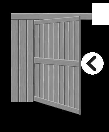
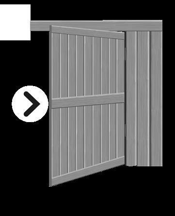
LEFT HAND OPENING
Side face of Post Front face of post
Square

Note the lower notch on side of Mounting Bracket (jig).
RIGHT HAND OPENING
Side face of post Front face of post
Mark 13mm hole inside template.

Square
Note the lower notch on side of Mounting Bracket (jig). A
Side face of post Front face of post Front face of post Side face of post

Mark ½” (13mm) hole inside template.
Note the lower notch on side of Mounting Bracket (jig).

5⁄32” (4mm)
1⁄2” (13 mm)



9⁄16”– 3⁄4” (14–19 mm) TIMBER
6. Screw on backing plate with 4 small screws

IMPORTANT:
Ensure padlock symbol is always at the top.
IMPORTANT:
Ensure padlock symbol is always at the top.
8. Insert Rod into Push Button – Click In
Depress push-button
Depress push-button
Leave screws loosely fastened to allow for final vertical adjustment.
Check Striker Bar is centered
Check Push Button Operation
Check Key Operation on both sides
Q: Why don’t I hear a “click” when locking or unlocking? The “click” means the latch is engaging properly. If you don’t hear it, the push rod may have been cut incorrectly. Remove the latch and double-check the first installation step.
Q: Why won’t my key turn fully? This is often caused by an incorrect push rod length, which can stop the mechanism from moving fully. Remove the latch and check that the rod is the correct length.
Q: Why isn’t the latch locking or unlocking properly?
If the push rod is too long or too short, it can affect how the latch works. Re-check the installation steps and adjust the rod if needed. We supply a spare rod.
Q: What should I do if the problem continues? Revisit the first installation step and confirm the push rod length. If you still have issues, please visit our website and contact your local D&D support team for help www.ddtech.com