1 minute read
Geosynthetic Reinforcement

Geosynthetic reinforcement is an engineered product that is typically comprised of polypropylene, polyester, or other high-tensile material. Used in conjunction with segmental retaining wall blocks, it helps stabilize the soil mass behind a wall. Depending on the wall design, the length and the number of grid layers will vary.


Generally, grid strength is in the roll direction. As it is unrolled, it is in the same direction it should be installed. Biaxial grid is another option in which the strength is the same against roll direction as it is in the roll direction.
Basic Grid Reinforcement
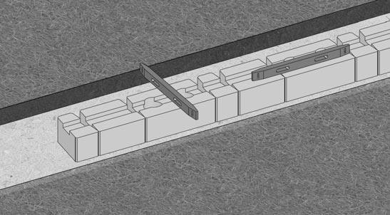
Step 1 - Preparation for Grid
The area behind the wall on the grid layer needs to be level with the top of the block and to 95% of the Standard Proctor (ASTM D698).
Step 2 - Grid Placement
Place the grid as close to the face of the wall without exposing it after successive placement of blocks. Ensure the grid is placed with the strength direction perpendicular to the wall. Check grid manufacturer specifications for proper grid placement instructions.

Step 3 - Preparation for Backfill
Place the next course of block. Pull the grid back and stake it so it is taut and free of wrinkles.
Step 4 - Backfill and Compact
Place 3/4" to 1" clean fill (crushed rock) within the cores and a minimum of 12" behind the blocks. Place and compact backfill on the grid in lifts no greater than 8". When possible, it is recommended the backfill is deposited directly behind the wall and pushed to the end of the grid to ensure it remains taut and wrinkle-free.
Convex Curve
Step 1 - Grid Placement
Place grid following the contour of the curve.
Step 2 - Successive Grid Layers
Overlapping layers of grid on a convex curve require a minimum of 3" of fill between them for proper anchorage. Repeat these steps for successive specified grid layers.
Concave Curve
Step 1 - Grid Placement
Making sure the strength direction of the grid is perpendicular to the wall face, align the cut grid sections so they follow the contour of the concave curve. Grid layers should not overlap. An engineer will specify grid lengths.
Step 2 - Successive Grid Layers
After the next course of block is placed, lay the grid to cover the area of unreinforced soil below. This will ensure 100% coverage. Repeat these steps for successive specified grid layers.
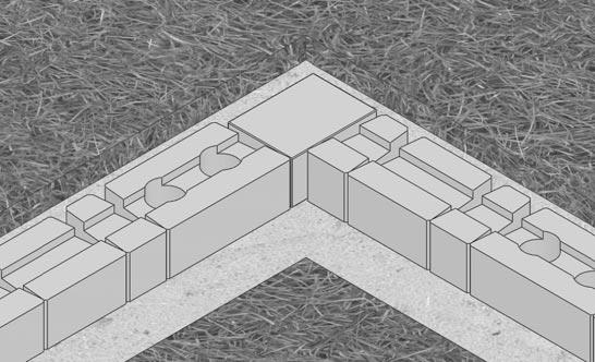
INSIDE/OUTSIDE 90˚ CORNERS
Step 1 - Grid Placement
On an 90˚ corner, it is important that grid layers do not overlap at the corner. Place the first grid layer per plan at its design elevation and length.
Step 2 - Successive Grid Layers


In the corner and on the next course of blocks, place a layer of grid perpendicular to the previous layer of grid. Repeat these steps for successive specified grid layers.