cibse
Journal Electric avenue
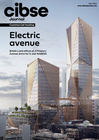
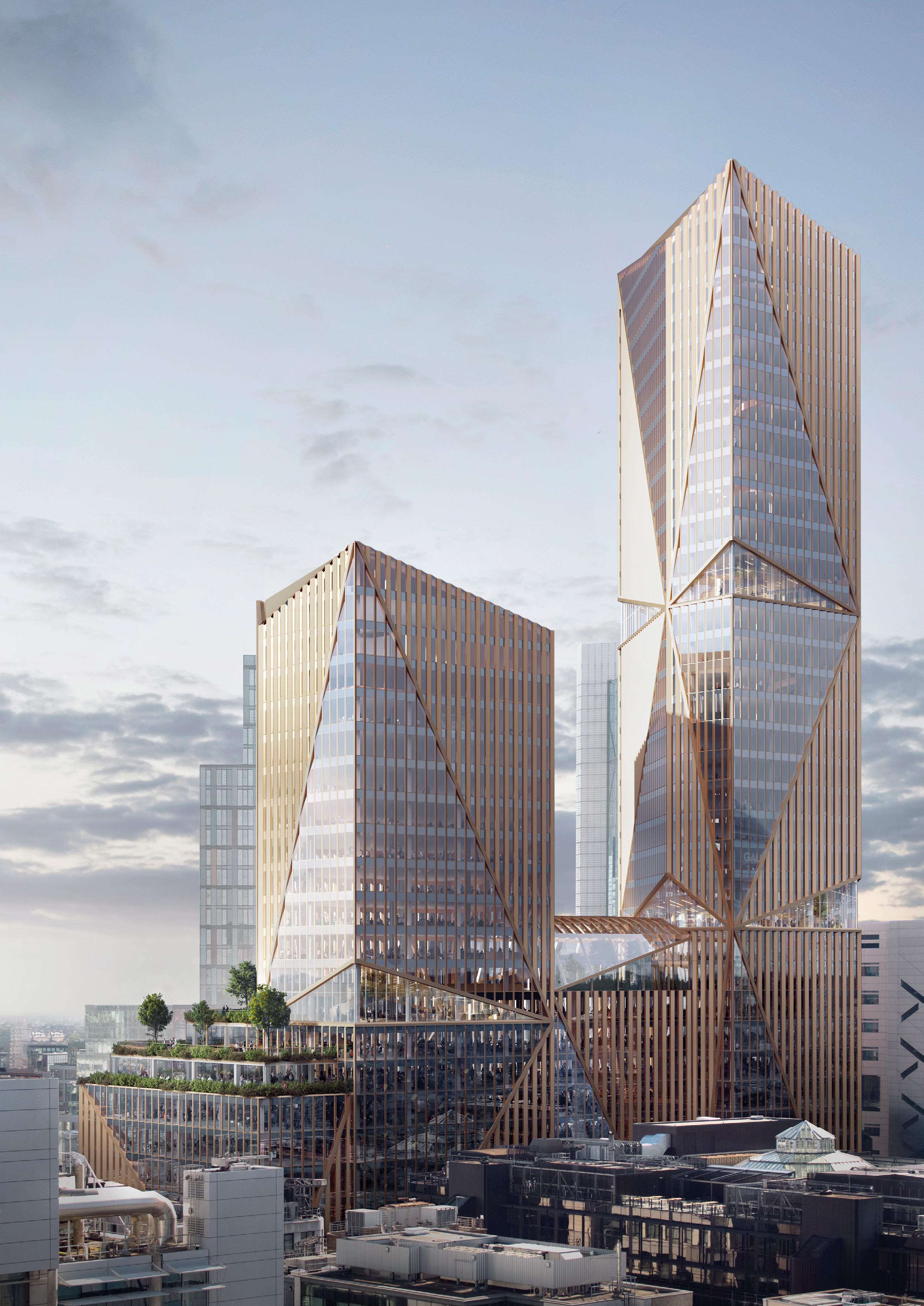
British Land offices at 2 Finsbury Avenue strive for 5-star NABERS

On track for carbon savings
The award-winning Locomotion New Hall proves that protecting the world’s most significant railway heritage doesn’t require high-energy HVAC. Andy Pearson reports
When the Science Museum Group decided to create a new building for its railway collection at Locomotion in Shildon, County Durham, it set its design team the challenge of protecting its historic railway rolling stock while avoiding the high energy demands associated with more traditional museum environmental control.
The result is New Hall. Designed by Buro Happold working with AOC Architecture, the team has delivered an exceptional, yet simple building that has eschewed complex HVAC systems in favour of a highly insulated envelope, airtight construction and a low-energy heating strategy to maintain the conditions necessary for heritage conservation.
This ambitious approach was recognised at the 2026 CIBSE Building Performance Awards, where the scheme won Public Building of the Year. The judges acknowledged that
Buro Happold went above and beyond the brief, describing its solution to balancing the needs of visitors and conservation as ‘simple and robust with low energy demand’.
Locomotion is one of several museums operated by the Science Museum Group, including the National Railway Museum in York and the Science and Industry Museum in Manchester (see ‘Powered by the next industrial revolution’, CIBSE Journal, November 2025, bit.ly/CJNov25PH).
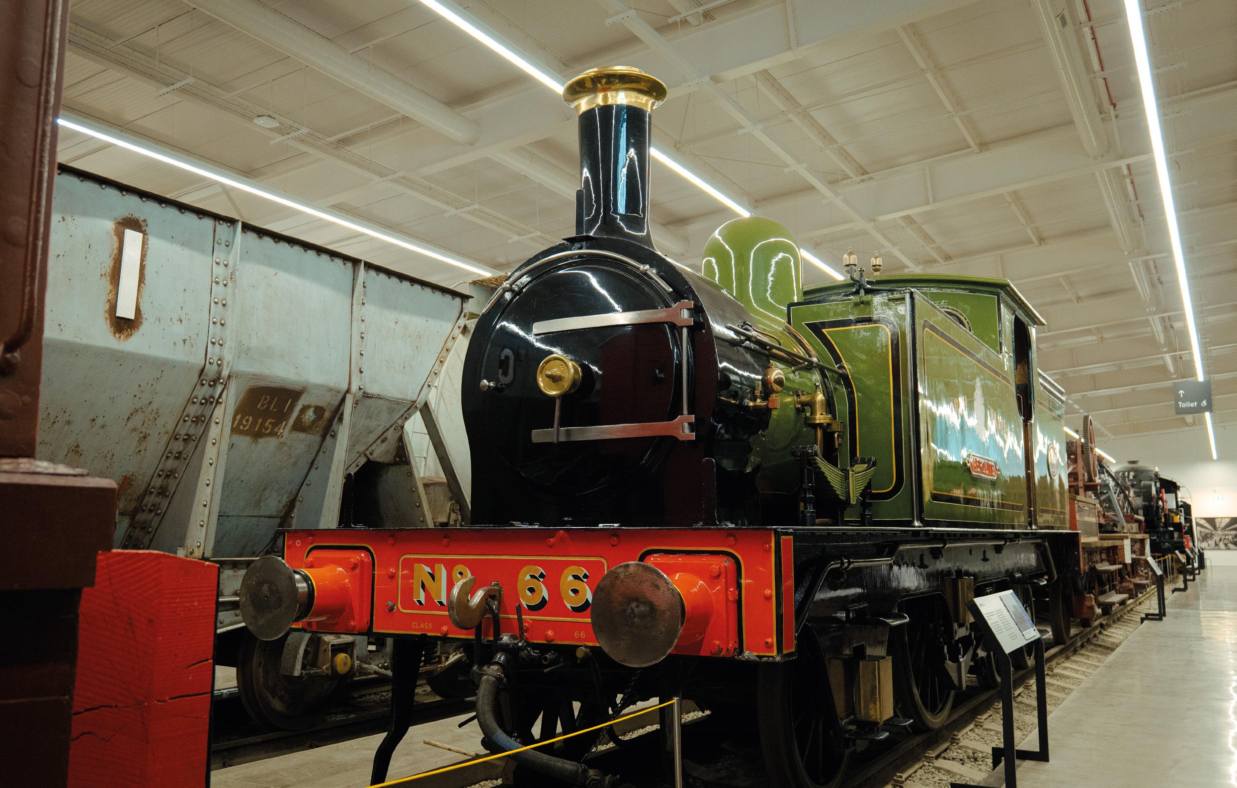
Locomotion is located beside the route of the world’s first public railway, which opened in 1825 with a train hauled by George Stephenson’s Locomotion No 1. The steam engine is on display in the Main Hall at Shildon, part of one of the most significant collections of railway heritage in the world. The museum’s collection is so large that some of the rolling stock at Shildon has to be stored outside.
The New Hall building needed to preserve the precious exhibits while
also allowing the public access to view the unique collection. As a result, its architectural design balances the industrial scale of a railway engine shed with a welcoming visitor experience.
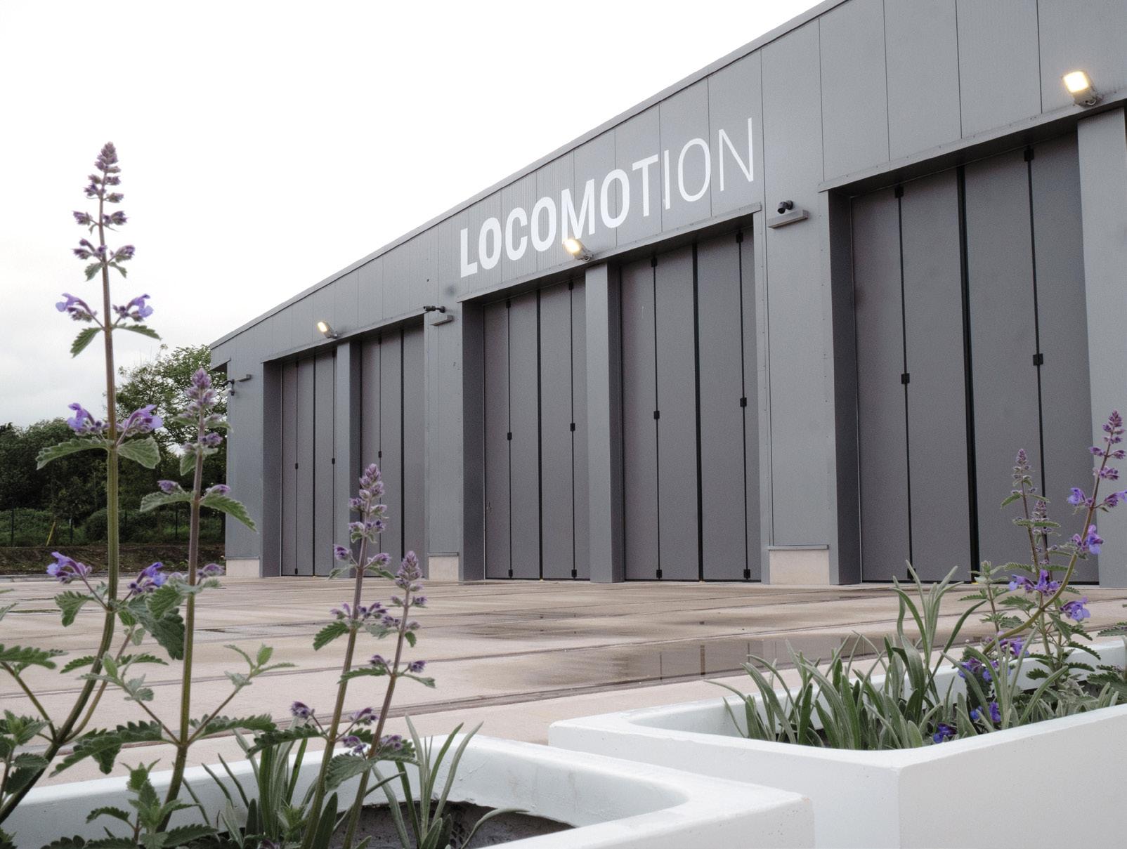
It has a wide, mono-pitch roof supported on a steel portal frame enclosed in high-performance cladding panels. On its west elevation, six giant doors provide access for the rolling stock from the concrete apron outside.
Inside, polished concrete platforms allow visitor access between the six sections of track that accommodate the exhibits. Glazing is confined to the north elevation, to prevent sunlight damaging the exhibits and to limit the impact of any solar gains on the environment in the hall.
Museum environmental control is often associated with highly regulated temperature and humidity delivered through complex HVAC systems. New Hall’s engineering team, however, recognised that its function – essentially a large storage building for large
exhibits – allowed for a different approach. Instead of tightly controlling temperature, the project focused primarily on maintaining stable humidity levels. Close collaboration with the collection care team helped define appropriate environmental parameters for rolling-stock preservation.
‘Locomotives are made from a mix of materials – steel, wood and other components – and high moisture levels in the air can be problematic,’ says Lawrence Williamson, associate mechanical engineer at Buro Happold. ‘The key requirement was to protect them by controlling humidity.
‘Environmental design criteria were also informed by heritage conservation guidance, including BS 4971, which sets out recommended environmental ranges rather than mandating tight, actively controlled conditions.
‘What matters most is avoiding large temperature fluctuations and keeping humidity within a safe range.’
Environmental targets for the hall were to maintain temperatures ‘broadly between the mid-teens and mid-20s Celsius, and a stable relative humidity between 35% and 60% that allows for seasonal variation’, adds Williamson.
The team focused on ensuring the building itself would stabilise the
Performance data
* For period 25/04/2024 to 31/03/2025 † For period 11/03/2025 to 16/09/25 since installation ‡ For period 01/04/2025 to 31/03/26
internal environment. At the heart of the strategy is a relatively highperformance building envelope, designed to minimise heat loss and prevent uncontrolled air infiltration.
‘If you get the fabric right, the internal environment becomes inherently stable,’ says Williamson. ‘Once conditions are established inside the building, they change very slowly.’
Highly insulated panels clad New Hall. Achieving an appropriate level of airtightness required close collaboration between engineers, architects and the contractor, as the manufacturer would only guarantee an
air permeability of 3m3·h-1·m-2 @ 50 Pa. Cladding contractor Aspect Facades, working with design and build contractor Nationwide Engineering, set out to improve on this figure for the installation.
The building’s six pairs of enormous access doors posed a particular challenge: Locomotion’s exhibits have to be moved in and out of the building along rail tracks, which require industrialscale openings that could easily compromise airtightness.
Originally, the intention was to seal around the doors once the rolling stock was in place. However, an initial airpressure test showed the doors to be surprisingly airtight, so the decision was made to leave them unsealed. This has the benefit of enabling the museum to easily open the doors to facilitate further vehicle moves when required.
The two visitor entrances incorporate lobbies with sequential opening doors to limit air exchange when people enter the building.
The airtight envelope was key to facilitating Buro Happold’s deliberately simple approach to environmental control. Museum buildings typically use large air handling units with heating, cooling and humidification to maintain tightly controlled conditions., but New Hall avoids this complexity. Instead,
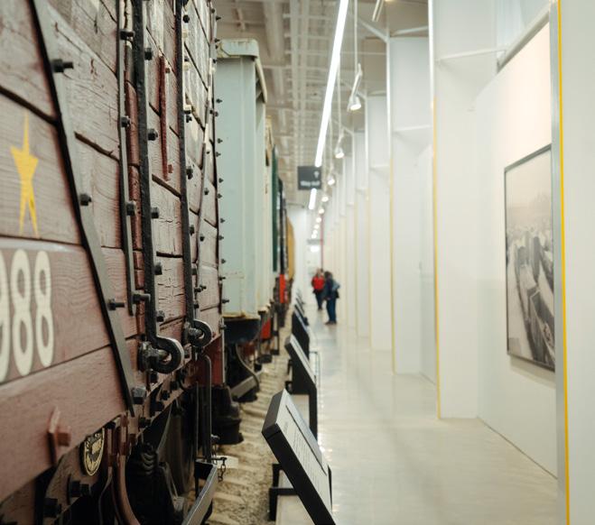
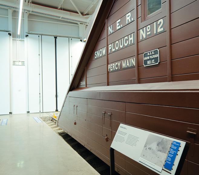
doors meet airtightness requirements without the need for sealing
humidity is controlled by an underfloor heating system embedded within the polished concrete platforms that provide visitor access between each of the tracks.
‘We essentially removed the middle layer of HVAC,’ Williamson explains. ‘Rather than heating air through big plant systems, we deliver low-grade heat directly into the building fabric.’
The underfloor heating circuits are supplied by air source heat pumps, operating at a relatively low temperature of 45°C flow and 40°C return. Because the building’s heat loss is minimal, the total heating demand is modest, so two small heat pump units are sufficient to serve the entire hall, providing both capacity and redundancy. ‘If one unit is down for maintenance, the other can still keep the building stable,’ Williamson says.
Unusually, the heating system is not designed to keep visitors warm; it is controlled to maintain the humidity conditions necessary to preserve the collection. ‘If humidity rises, gently warming the space lowers the relative humidity,’ Williamson explains. ’So the heating system is effectively controlling moisture levels.’
This solution means the heating system may occasionally operate during warmer humid weather. ‘The museum made it very clear that conservation comes first,’ Williamson says. ‘If humidity rises, we’ll run the heating system to bring it back down, even if it’s a warm day.’ In practice, however, the building has maintained stable conditions without a noticeable impact on visitor comfort.
Ventilation requirements for visitors are addressed through a small mechanical ventilation with heat recovery (MVHR) system. This has no heating coil, with the temperature of the fresh air supply tempered through a heat exchanger within the unit. The unit is sized to deliver fresh air for 80 visitors, with CO₂ sensors used to modulate the airflow to ensure energy efficient operation. Importantly, the ventilation system plays no role in environmental control. ‘It’s purely there for people,’ says Williamson. ’The building itself is doing the environmental stabilisation.’
The building services installation is minimal. A compact plantroom houses
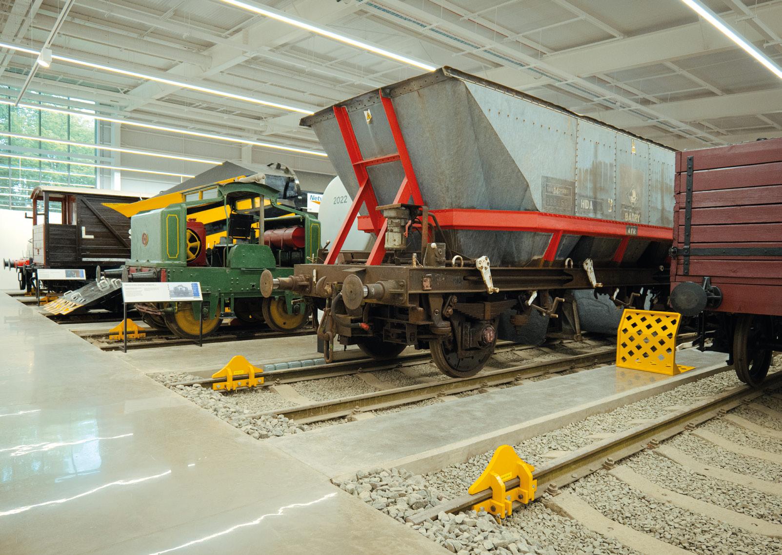
‘Instead of tightly regulating temperature, the project focused primarily on maintaining stable humidity levels’
the MVHR unit, heating circulation pumps and associated equipment. The system uses a thermal store to buffer the heating system and assist with heat pump defrost cycles in cold weather.
Elsewhere in the building, services are limited to LED lighting and a small number of ancillary spaces, such as a single toilet, a comms room and storage area - visitor amenities including a café and toilets are all located in neighbouring museum buildings.
New Hall opened in May 2024. Environmental conditions are monitored and controlled through a Honeywell building management system, allowing remote monitoring by the museum’s facilities team. This has shown that Buro Happold’s approach to New Hall
has delivered an exceptional energy performance of 49.7kWh·m-2 per year, as shown on the latest Display Energy Certificate. This exceeds the UK Net Zero Carbon Buildings Standard benchmark and surpasses the recommended target for a cultural building holding a collection.
The figure is also a massive improvement on the predicted energy use at RIBA Stage 3 of 137kWh·m-2 per year. Williamson attributes this primarily to the contractor achieving an airtightness of 1.45m3·h-1·m-2 @ 50 Pa, which is a significant improvement on the 3m3·h-1·m-2 manufacturer’s data allowed for in the initial modelling.
The addition, post-completion, of 268m2 of photovoltaics on the building’s roof has resulted in an energy use intensity of 23.8kWh·m-2 per year between April 2025 and March 2026. By investing in a high-performance envelope and using thermal mass to moderate environmental conditions, the scheme shows it is possible to avoid the energy-intensive HVAC infrastructure often associated with museum buildings.
Its recognition at the CIBSE Building Performance Awards 2026 suggests this approach may offer valuable lessons for other heritage and cultural projects seeking to balance conservation, sustainability and operational simplicity. l
Underfloor heating is supplied by air source heat pumps
Commercial & Industrial Solutions
+ Commercial wall hung up to 900kW
+ Commercial floor standing gas boilers up to 5.12 MW
+ Industrial boilers up to 22 MW – Electric/Gas/Oil
+ Commercial air and ground source heat pumps up to 560kW
+ Combined heat and power units
+ Solar thermal and PV
+ DHW cylinders and buffer vessels

Contact your Commercial Area Sales Managers
Making the moat of it
Do water source heat pumps offer an environmentally friendly, efficient and visually discreet solution for decarbonising heat in historic buildings? A report from Historic England suggests they can, reports Phil Lattimore

Areport commissioned by Historic England has concluded that closed-loop water source heat pump (WSHP) systems are a viable and readily available way to discreetly decarbonise heating systems in historic buildings.
The report, Heat pumps in historic buildings The viability of water source heat pumps in historic buildings (bit.ly/4sNEW02), explores how well-designed WSHP systems perform in practice, and how they can be integrated efficiently with existing pipework and radiators.
Looking at five historic buildings that have had WSHP systems installed, the report sought to identify examples of best practice that have enabled good system performance, as well as common mistakes that have led to poor performance. The intention was to use the findings from the case studies to inform future work and strategy, particularly in identifying the design,
control and maintenance factors that determine whether WSHP systems perform effectively in historic buildings.
Visits to the five case study buildings – located in Somerset, Cambridgeshire, Warwickshire, North Yorkshire and Norfolk – took place between February and April 2023, with engineers from Max Fordham carrying out site surveys. They also questioned building users on thermal comfort, noise levels, running costs, control management and maintenance.
With many stately homes built close to a body of water, the report concluded that WSHPs can be particularly suitable, offering a more visually discreet solution than an air source heat pump (ASHP) system and a more straightforward installation than a ground source heat pump.
When used for conservation heating, WSHPs can operate efficiently with existing radiators and pipework, minimising the cost, disruption and visual impact of upgrading.
In terms of effectiveness, the report suggests that issues with system performance are often the result of its configuration rather than the WSHPs themselves. Only one of the five sites in the case study experienced ‘significant difficulties’ extracting heat from the source water, because of an open-loop setup.
Noise levels were similar to other heating system components (as they are often installed in plantrooms).
Controls were another key factor in optimising the performance of WSHP systems, with the report highlighting the importance of building users having a good understanding of how to use controls to maximise efficacy. However, it found that the availability of skilled maintenance and installation contractors could be an issue. l
Other Historic England heat pump guides are at bit.ly/CJHEHPs. Read a summary of ASHP studies in large buildings at bit.ly/4tYeEcu
Site 1 Medieval Bishop’s Palace outbuildings
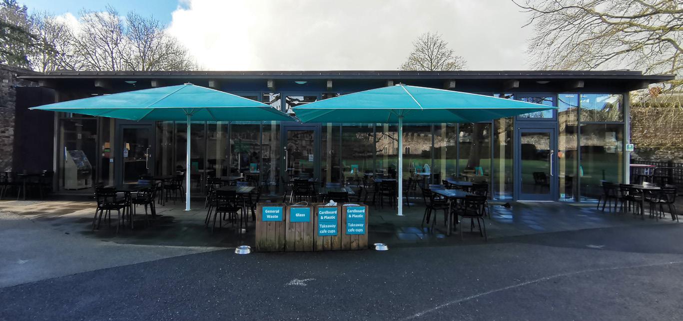
This Somerset site used a Dimplex SIH 20TE 20kW WSHP to heat the outbuildings. A closed-loop collector placed within the moat on a sunken platform provided the heat source, so had no visual impact on the building.
Underfloor heating was used in the toilets, learning centre and cafe, while radiators heated the office. A 500-litre hot-water cylinder serves these, and there were no issues with temperatures, apart from in the learning centre, and no noise issues from the WSHP.
An energy management company evaluated the site and found an operating coefficient of performance (COP) of only 0.75. System settings were altered to improve the COP to 2.5, which was still lower than the expected 3.0; suboptimal performance can be caused by the WSHP targeting a high flow temperature, or a large temperature difference across the flow and return for the WSHP, but the cause wasn’t clear.
The report states that a WSHP in the main palace would reduce energy use and running costs compared with the current direct electric system. Engineers’ rating Technology choice Thermal comfort
Design/installation quality
Site 2 Jacobean-style house
In 2018, a 204kW WSHP system replaced the oil-boiler heating system at the Grade I-listed country house in Cambridgeshire, parts of which date back to 1135. It uses six CTC EcoPart 434 WSHPs with an open-loop collector.
The open-loop WSHP system extracts and returns water from a small watercourse on the site. Five 34kW units provide conservation heating and domestic hot water to the main house, and one 34kW unit delivers comfort heating to the staff cottage, with heat primarily delivered through existing radiators in the main house and new radiators in the cottage.
The installation had no visual impact on the building and the basement plantroom produced no noise issues. However, the engineers found that the WSHPs were not working. Although functioning as designed for 12-18 months, a lack of river maintenance,
personnel changes and collapsed system maintenance resulted in the submersible pumps and filtration system frequently failing. Locating the pumps under a bridge (to reduce visual impact) made them difficult to maintain, with suspected blocked filters and an airlock in the pipework. Mild steel, rather than stainless steel, components also caused damage. Finding a contractor to fix it proved difficult. The client was interested in converting the open-loop system into a lower-maintenance closed-loop one for this and future projects. Engineers’ rating Technology choice Thermal comfort Design/installation quality
Site 3 Mansion house
Constructed in 1570, the mansion house has been extensively modified, including significant renovations and extensions in the 1920s and 1930s.
Three Dimplex WSHPs were used to heat the main house, office
accommodation and flats on this site, with all three connected to a shared closed-loop collector on a sunken platform in the lake next to the house.
A single 75kW WSHP and a 1,000-litre buffer vessel provided conservation heating to the main house, which used the existing historic radiators to deliver heat. Heating for thermal comfort was provided on separate circuits to the offices and flats, powered by a 40kW and 20kW WSHP sharing a 500-litre buffer vessel. The offices and flats used modern radiators.
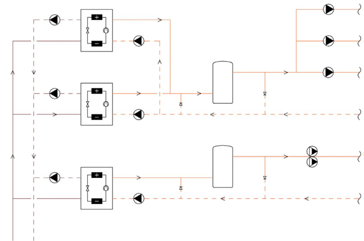
The research engineers found the system well designed, but when they compared what had been installed to a schematic of the design, a non-return valve appeared to be missing, reducing the heating system flow temperature by allowing return water to mix with the outgoing flow. This reduced efficiency and meant insufficient heat was delivered to some parts of the building.
Lower-temperature conservation heating allowed existing large, cast
Medieval Bishop’s Palace outbuildings
Water source heat pumps Historic England report
iron radiators to meet heat output requirements. Separate WSHPs for thermal comfort and conservation heating allowed each to be sized to its purpose, enabling each WSHP to operate at the lowest possible temperature and maximising efficiency.
Engineers’ rating
Technology choice
Thermal comfort
Design/installation quality
Site 4 Stately home
Construction of the building began in 1699 and was completed in the 1750s, with additions during the 19th century, plus extensive restoration after a fire.
Two 144kW Dimplex SI 100TE WSHPs were installed in 2009, using a closed-loop collector system to collect heat from a pond. They provide heating to all heated areas of the main house and hot water to the west wing.
In 2020, two 73kW Dimplex SI 75TU WSHPs were installed to provide heating to additional areas of the west wing
and to accommodate the installation of more hot-water appliances. The total heat pump capacity was 97W.m-2
There was minimal visual impact from the system installation in the basement plantroom, and no noise issues. Using the historic radiators saved money, but leaks in some needed repair.
The report acknowledges the foresight of ensuring the system is set up to allow more heat collectors to be added. The WSHPs appeared to be in good working order, although the engineers found pipework insulation was damaged in places, potentially leading to condensation, corrosion and leaks.
The report highlights the lack of temperature control, with the pipework configuration allowing it to be set as only one zone for the whole building. Some rooms in the east wing had low thermal comfort levels.
Engineers’ rating
Technology choice
Thermal comfort
Design/installation quality
Water to Water
Site 5 Stately home
Two Dimplex SI 130 and SI 75TU WSHPs were installed in this Grade I-listed 17thcentury stately home in Norfolk in 2016, providing heat pump capacity of 205kW, and extracting heat from a nearby lake in a closed-loop system.
The WSHPs, which deliver 50W m-2 capacity (of usable floor area), provide conservation heating to visitor areas and comfort heating to staff offices and accommodation, using historic radiators that were fed by an oil-fuelled boiler.
The lake’s proximity made the water source an excellent choice for high-efficiency heating, with minimal visual impact or noise issues from the plantroom. Thermal comfort was excellent, with staff and volunteers feeling comfortable in all areas. However, the report cites a lack of zoning control of the heating as an issue.
Engineers’ rating
Technology choice
Thermal comfort
Design/installation quality


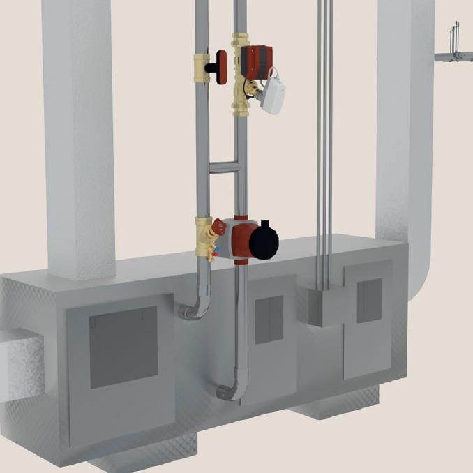

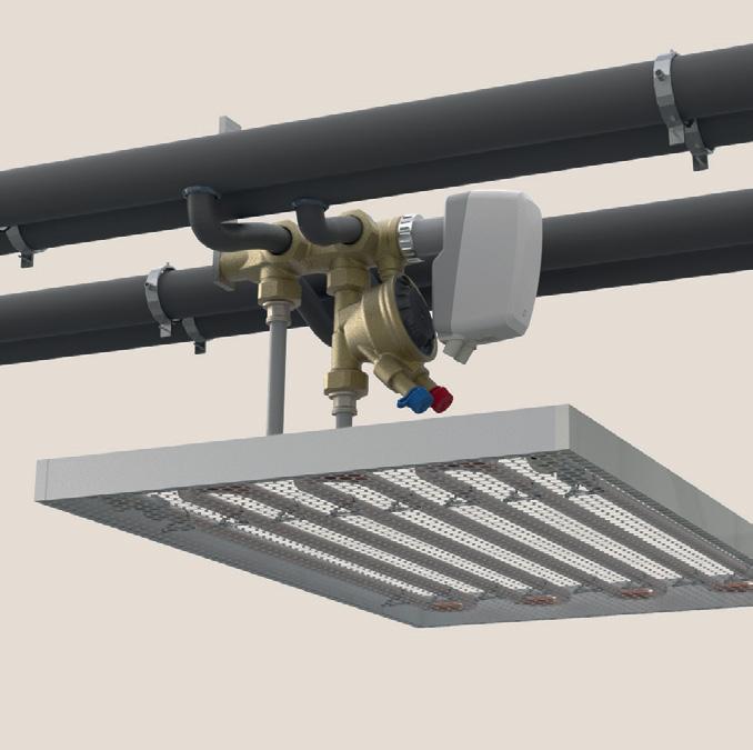
Driving Efficiency in Every Terminal Unit
Hydronic solutions for stable flow and precise temperature control at all operating conditions.
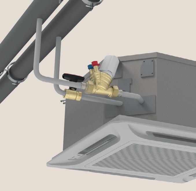
Fan Coil Units, Chilled beams, Climate ceilings and Air Handling Units are only as efficient as the hydronic control design behind them.
Our valves and actuators protect your design intent by delivering accurate flow limitation and stable part-load control, supported by transparent data that enables continuous optimisation as system conditions change.
Our pressurisation, air and dirt separation, and degassing solutions safeguard the hydronic system by maintaining correct pressure, removing air and contaminants, and ensuring long-term operational stability.

































Clarification on HNTAS process
Dear Editor,
We welcome the recent CIBSE Journal article ‘Preparing for the Heat Network Technical Assurance Scheme’ (February 2026) and agree with its overall premise that HNTAS is a necessary and positive step for the sector.
As the technical author responsible for developing HNTAS, we would, however, like to clarify a small number of points where the article may inadvertently have given readers an incomplete or misleading impression of how the scheme will operate in practice.
HNTAS Stage 1 scope and intent
The article notes the increased level of requirement at HNTAS Stage 1. This is intentional and evidence-led. Historic analysis of heat network underperformance shows that fundamental design decisions made at early concept stage are the root cause of many later failures. Stage 1 focuses on ensuring that critical performancedetermining choices are sound before they are locked in. This approach is designed to reduce downstream risk, rework and cost, rather than add unnecessary burden.
Stage 1 does not constrain iterative or creative design
The suggestion that HNTAS Stage 1 restricts the iterative and creative
nature of RIBA Stage 2 is not the intent of the scheme. HNTAS assessment occurs at the end of each stage, not throughout it. Design teams retain full freedom to iterate, test options and refine solutions in the same way as they do today. The scheme does not interfere with the design process; it simply provides an assurance checkpoint once that process has concluded.
Clarification on progression with nonconformities
The statement in the article that ‘projects may not be able to proceed until all… nonconformities are resolved’ is incorrect. Projects can proceed through HNTAS stages where:
l The assessor is confident key performance indicators can be achieved
l There are no key failures
l There are no major technical issues outstanding.
This is a deliberate feature of the scheme, designed to avoid unnecessary delay while maintaining performance and consumer-protection outcomes.
TS1 vs CP1 references
The article uses CP1 and TS1 interchangeably. Under HNTAS, TS1 is the correct and sole technical reference. While TS1 builds on CP1, it has been rewritten, tightened and structured
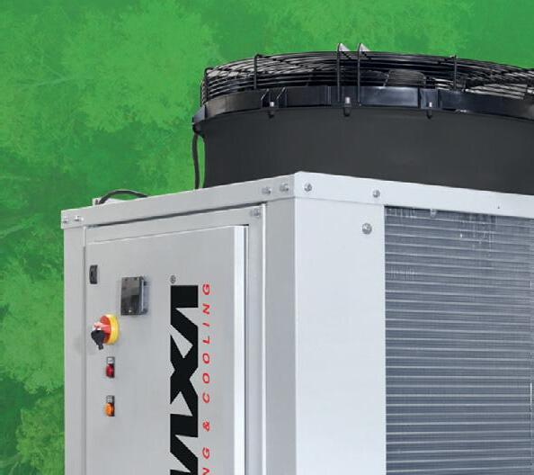
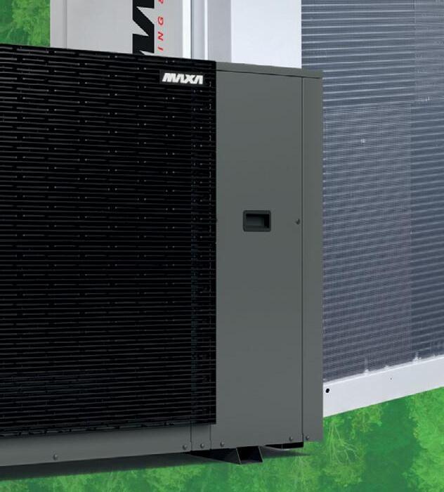
OMICRON Zero
• Eurovent certified performance
• First air-source multifunctional heat pump and chiller unit using propane as a near zero GWP, natural refrigerant solution.
to function as a regulatory technical standard. Referring to CP1 risks confusion, particularly given that CP1 was voluntary and interpretive, whereas TS1 is mandatory and assessable.
Use of multiple assessors
This is described as a potential negative. In practice, this reflects standard peer review and ISO-aligned assurance, particularly for complex, safety and consumer-critical infrastructure. It improves robustness, consistency and confidence in outcomes, and is not unusual in regulated technical assurance environments.
We hope these clarifications are helpful. l
l Tom Burton, member of the HNTAS technical author team, FairHeat


Finsbury flex
Building services engineers at 2 Finsbury Avenue have taken a part-load approach to reflect the reality of flexible working. Andy Pearson finds out how Ramboll has engineered a system that aims to optimise efficiency whether the building is hosting a full house of 7,000 or a core team of 70
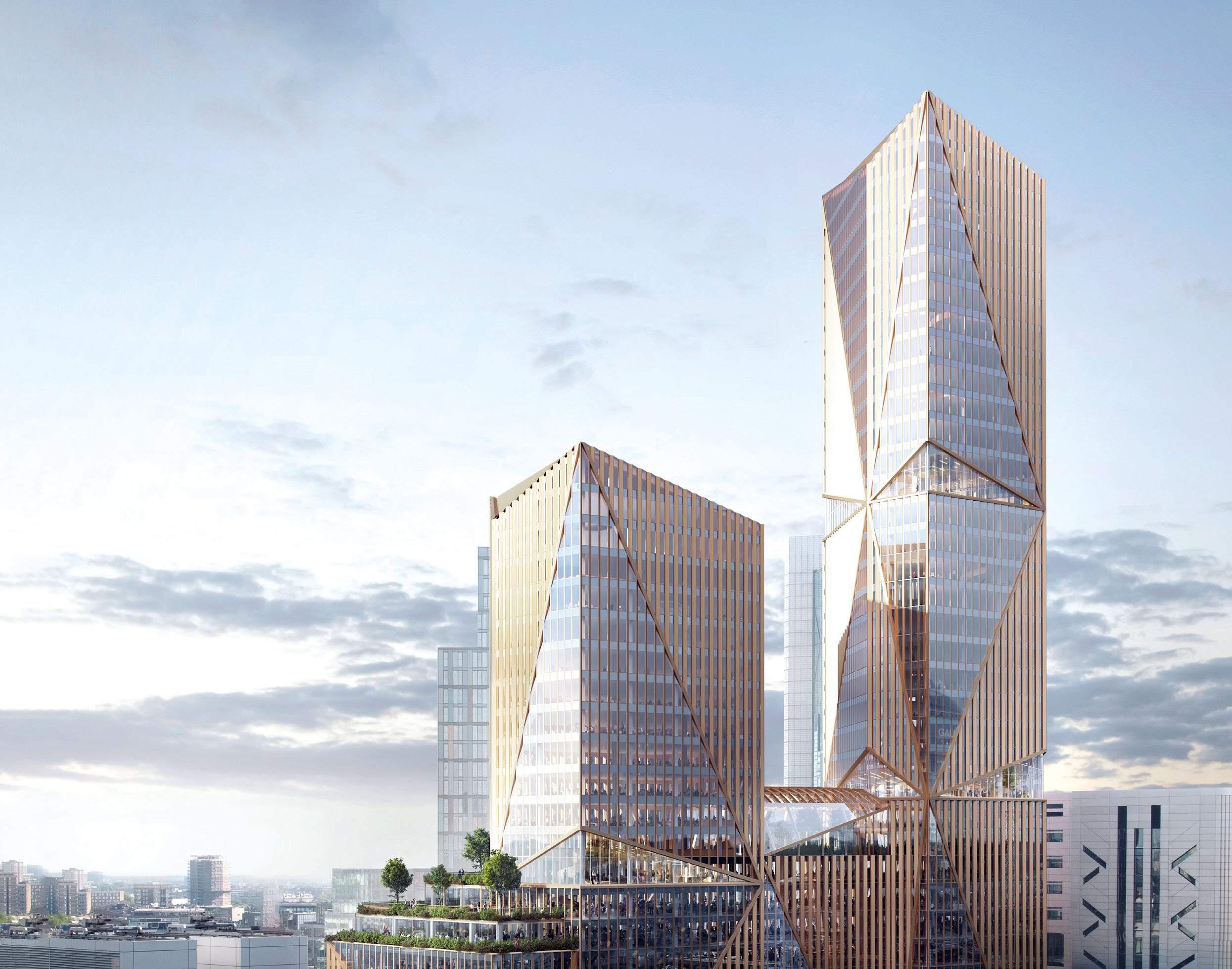
Expectations for the operational performance of commercial office buildings are set to be redefined by 2 Finsbury Avenue (2FA), in London. When completed in 2027, the scheme – developed by British Land and engineered by Ramboll – aims to achieve Breeam Outstanding, Well Platinum, an Energy Performance Certificate A rating and a NABERS UK Design for Performance scheme 5-star rating.
This established a total building energy target of 90kWh m-² per year, with landlord energy use targeting 55kWh.m-² and tenant energy 35kWh m-² per year.
To achieve these goals, Ramboll has taken a holistic approach to the building services design by shifting away from a peak-load approach. Instead, it has engineered and optimised systems for part-load, part-occupancy operation to reflect a post-pandemic world of hybrid working in amenity-rich spaces,
with increased focus on health, wellbeing and sustainability.
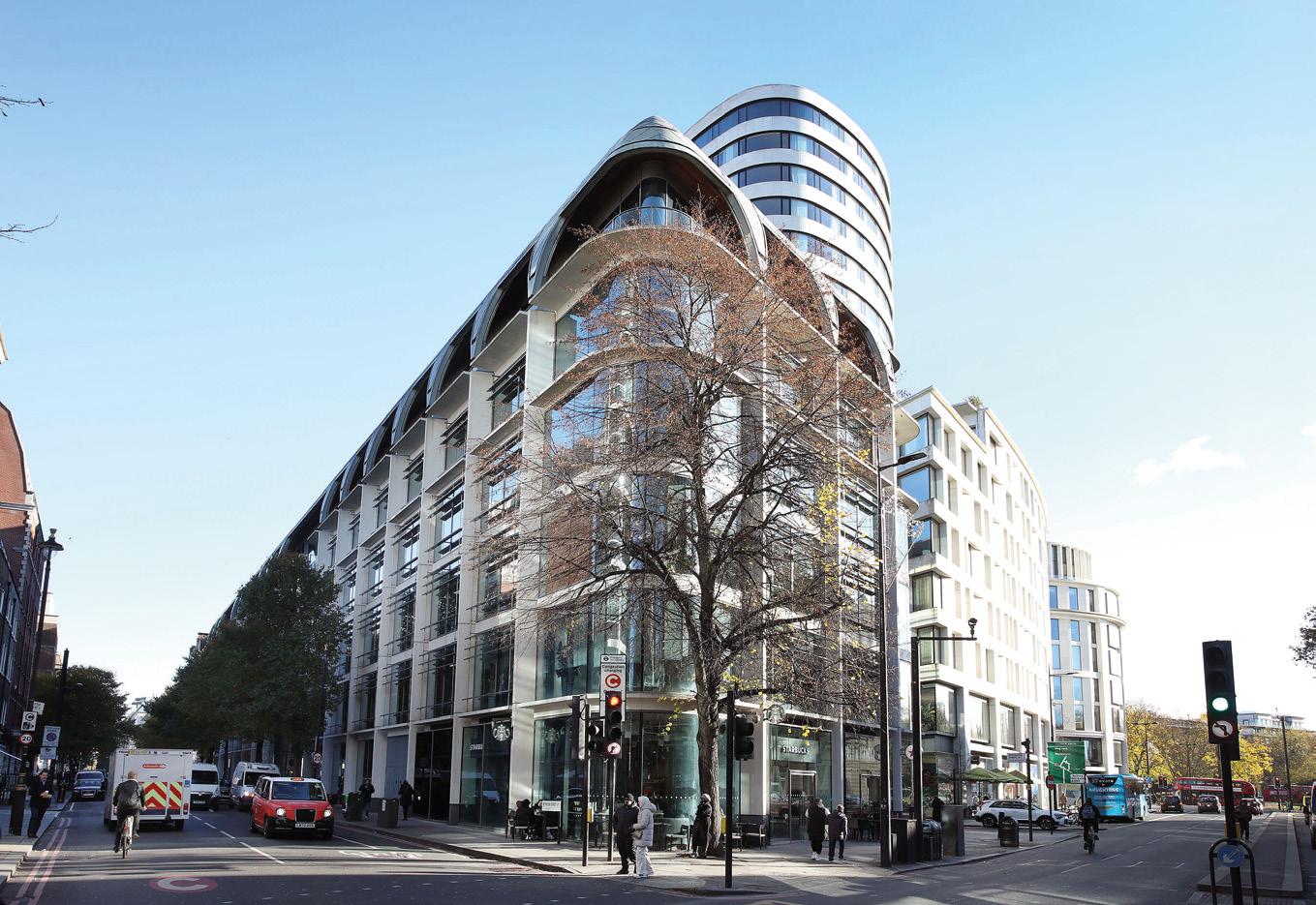
Ramboll’s route to meeting the low operational energy targets began with the building’s form and façade design. 2FA, in the City of London’s Broadgate campus, is unusual in that it comprises two towers – 37-storey East Tower and 23-storey West Tower – combined at the base by a 13-storey podium.
Early modelling identified peak solar gains would occur during the afternoon. Working with the project architects, 3XN, Ramboll analysed multiple façade geometries and orientations, simultaneously modelling variables such as glazing ratio, daylight availability, solar heat gain, glare risk and the thermal performance of glazing systems.
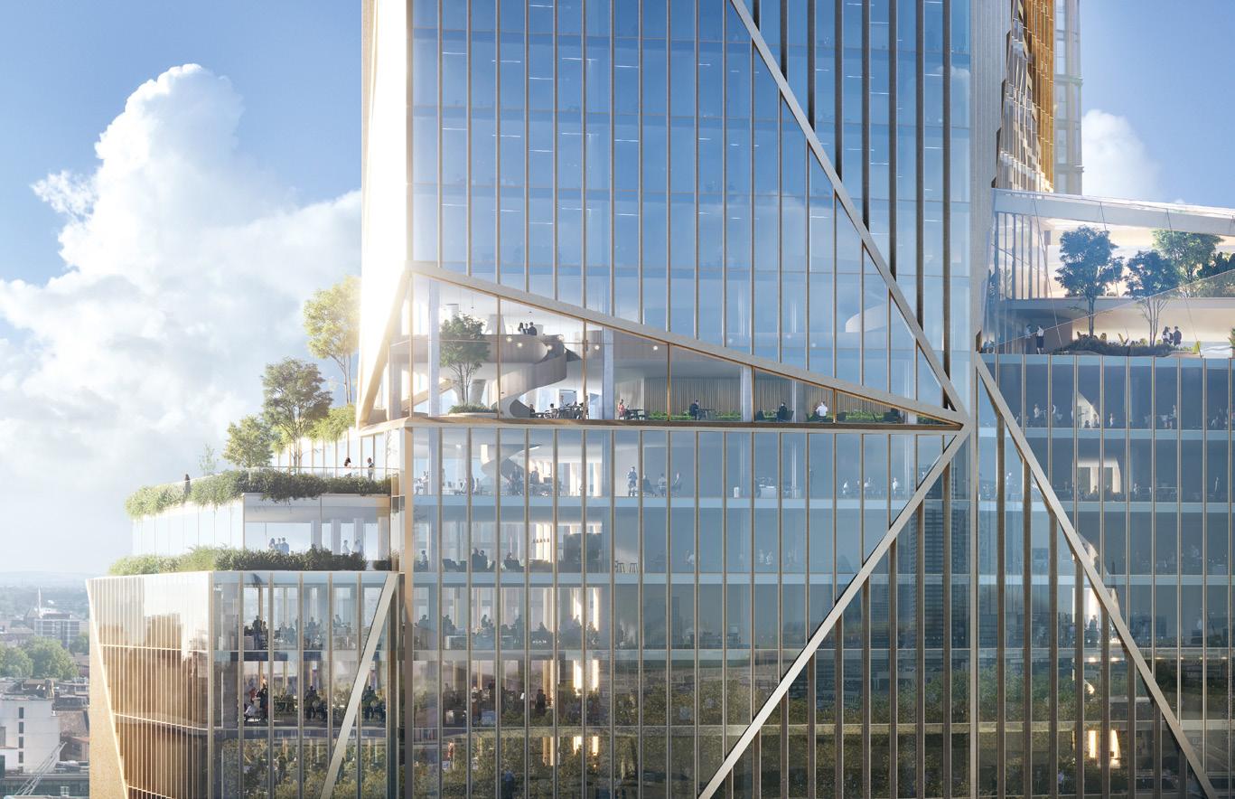
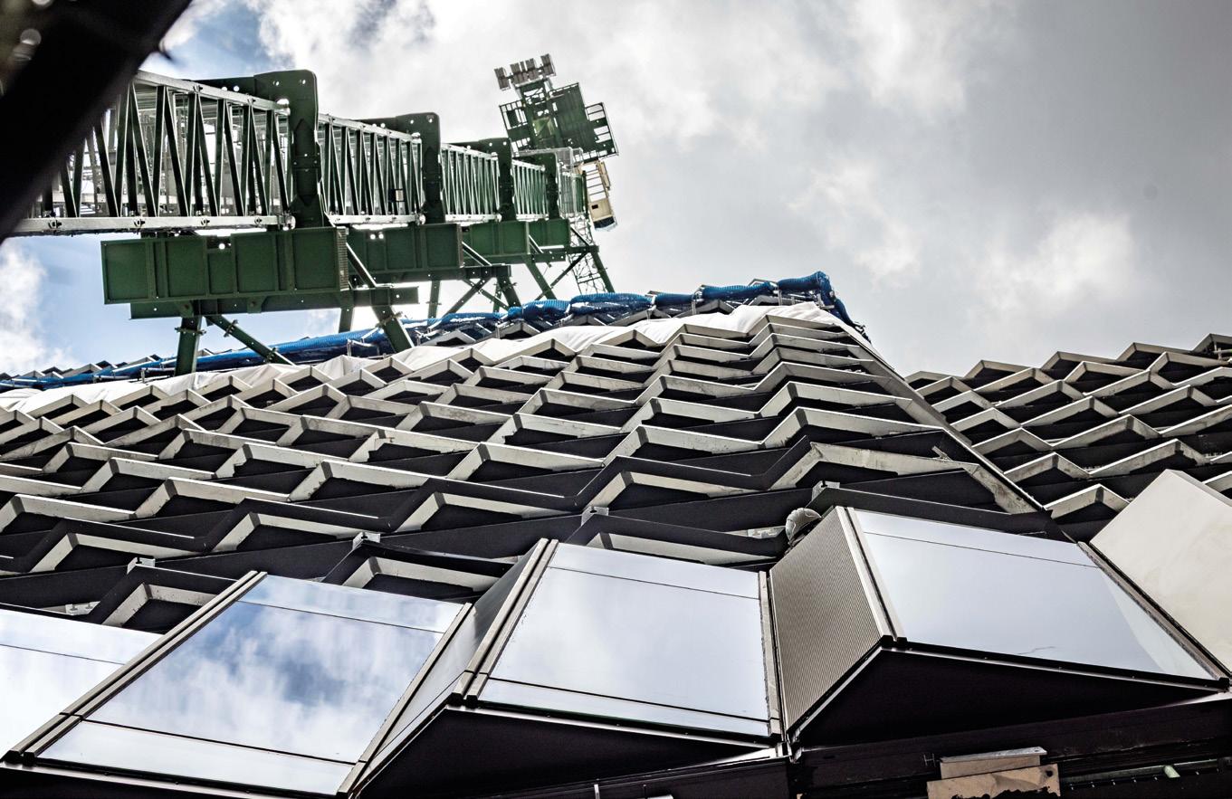
Its detailed analysis informed the final, optimised façade design, which incorporates saw-tooth modules orientated to maximise daylight while avoiding excessive cooling loads.
The design team adopted what Danny Coleman, technical director at Ramboll UK, describes as a ‘pragmatic approach’ to the challenge of highend commercial offices typically generating significant internal gains from occupants, equipment and lighting. ‘Over-insulating the envelope would risk increasing cooling demand,’ he says, ‘so the façade uses double glazing with a low solar G-value of around 0.25, combined with U-values that satisfied Part L energy modelling requirements for planning while avoiding over-insulating.’
The development was designed to operate without fossil fuels, but with a combination of electric heat pumps, boilers and high-efficiency chillers interconnected with sophisticated control algorithms. ‘The system can dynamically select the most efficient combination of plant for any given load and weather condition, to maximise operational efficiency,’ says Coleman.
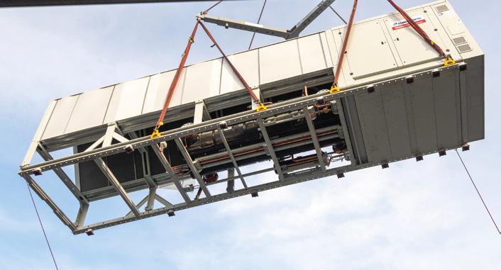
The system is designed to provide heat primarily using air source heat pumps (ASHPs), with electric boilers providing additional capacity. Heat pumps are sized to meet the bulk of the heat load. In the West Tower, heating is provided by two ASHPs: one 4-pipe unit and one 2-pipe reversible unit. In the East Tower, heating is provided by three units: two 4-pipe heat pumps and one 2-pipe reversible unit.
Rather than sizing the ASHP system to supply heat for extreme winter design conditions that will occur only rarely, the system incorporates three 750kW electric boilers. These provide top-up heat and additional resilience while minimising the embodied carbon, cost and space associated with redundant heat pumps.
The ASHPs also supply cooling in the West and East Towers. For this system, additional cooling capacity is provided by two water-cooled chillers in the West Tower and three in the East Tower.
A major benefit of this approach is making use of heat recovered from comfort cooling loads, tenant IT cooling, lift motor rooms and electrical switch rooms – which, says Coleman, can meet approximately 40% of the building’s demand for space heating and domestic hot water.
Optimising part-load performance
Ramboll’s engineering design used occupancy and performance data from British Land’s existing office portfolio to understand how buildings perform in practice, especially when operating at partial load for most of the year.
Part-load is common in spring and autumn, when loads can be relatively low, and for out-of-hours working, when only parts of the building are occupied. The system needed to accommodate these variations to meet indoor design conditions of 20oC heating and 24oC cooling.
Ramboll’s system is so efficient that even under very light loads – potentially as little as 2% of peak capacity – the entire system can, if necessary, operate from a single chiller or heat pump. Or, as Coleman puts it, the building has been ‘designed for 7,000 people, but will operate just as effectively for 70’.
Although each tower has its own chilled water and low-temperature
‘The system can dynamically select the most efficient combination of plant for any given load and weather condition’
hot-water systems, efficient part-load operation is achieved by the two networks being linked via plate heat exchangers in the basement.
‘Instead of running multiple machines at inefficient conditions, one piece of plant can serve both towers while operating near its optimal efficiency point,’ says Coleman.
The interconnection also enhances system resilience in the event of plant failure in one tower, by providing backup
heating and cooling from the other.
Achieving the 5-star NABERS UK rating requested in British Land’s brief is dependent on controlling and monitoring the engineering systems. The central plant will be operated using a plant optimisation system, which incorporates performance data for each piece of equipment, including efficiency curves for its operation under numerous conditions. This data helps the control system to select which items should
2FA’s saw-tooth façade is designed to maximise daylight and avoid excessive cooling loads
operate at any given time, improving plant performance significantly compared with conventional building management system (BMS) sequencing.
A comprehensive metering strategy also underpins the NABERS approach. Energy use is monitored across all systems, including tenant systems.
Tenant spaces are connected to the base-build systems via heating and cooling interface units. To maximise heat-recovery opportunities, tenants are required to prioritise use of the building’s chilled water system for their IT cooling requirements. Heat rejected from these systems is then captured and reused by the central plant. Similarly, all tenants are required to use heat supplied from the central plant.
Energy consumption in tenant spaces will be metered and monitored to support energy management, and to enable NABERS UK performance verification.
The ventilation system is designed to meet energy and wellbeing objectives, supporting the building’s aspiration for Well Platinum certification, and is sized to deliver 16L s-¹ per person. Rather than delivering fixed air volumes, the system operates using demand control based on maintaining a CO2 concentration of approximately 750ppm in each 200m2 office floor plate control zone.
Ventilation design targets a specific fan power of around 1.2W per litre per second. Oversized duct risers and connections to each of the office floors help achieve this. Duct connections are sized to enable occupancy of one person per 8m2 in a proportion of zones on each floor, with ventilation plant sized based on a diversified occupancy of one person per 10m2
Four large central air handling units (AHUs) – two in the basement and two on the roof of the East Tower – provide the bulk of the fresh air. These serve office areas in the podium and parts of the tower through ductwork distributed in the building cores. In addition, some areas are served by on-floor AHUs, which intake air and exhaust directly through the façade. This allows flexibility while limiting the scale of duct distribution within the towers.
While the building primarily uses mechanical ventilation, the façade has
Building on a performance win
With 2FA set to redefine expectations for the energy performance of office buildings, its developer, British Land, is showing that it is serious about building energy performance. Its head office is in York House, an existing building that it owns and that has already achieved NABERs 4*. The scheme won the Workplace of the Year – Retrofit at this year’s CIBSE Building Performance Awards, with the judges saying: ‘This project will bring about wider change by providing a blueprint for the developer’s wider commercial portfolio and other, similar, buildings.’ 2FA is proof that this, indeed, is the case.
motorised natural ventilators to support passive ventilation. These enable preoccupancy purge of the office floors and night-time ventilation, allowing warm internal air to be flushed from the building, helping to reduce cooling demand the following day.
‘During normal occupied hours, the ventilators are not intended to contribute to thermal conditioning of the spaces, as this would reduce the effectiveness of heat recovery within the mechanical ventilation system,’ Coleman explains. The ventilators are operated by the BMS during appropriate weather conditions.
The development also incorporates strategies to reduce water consumption, including low-flow fixtures and fittings, sensor-operated taps, dual-flush WCs, and PIR-controlled washroom systems. A reclaimed water system combines greywater recycling with rainwater harvesting to supply non-potable uses, such as WC flushing. The cooling system also contributes to water efficiency.
The water-cooled chillers reject their heat via hybrid coolers, which combine the efficiency of cooling towers during warm conditions with dry operation during cooler periods. Coleman says this approach ‘reduces water consumption while maintaining high cooling efficiency’.
At completion of 2FA, scheduled for June 2027, the brief calls for the building services solution to deliver a landlord energy use target of 55kWh m-2
Ramboll’s modelling is currently showing it to be 36.4kWh.m-2 – well below the NABERs target. Coleman says the independent design review required under NABERS has confirmed that the hybrid system design for 2FA should enable it to target the 5-star rating.
The building is 33% pre-let, and once it is 75% occupied, British Land will pursue a formal NABERS In-Use rating. This will verify whether Ramboll’s building services solution has delivered real operational performance and set a new benchmark for high-performance commercial offices in the UK. l
York House won Workplace of the Year – Retrofit at the 2026 CIBSE Building Performance Awards
Travelodge hotels: driving sustainability with Lochinvar air source heat pumps
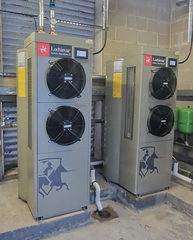
Travelodge, one of the UK’s largest budget hotel brands, operates more than 600 hotels, with 47,000+ guest rooms, across the UK, Ireland and Spain. As part of its commitment to achieving net zero operations by 2050, Travelodge has partnered with Lochinvar to upgrade domestic hot-water systems across its estate. Working with trusted installation partners Tech Asset Management and Commercial Maintenance Services, 25 air source heat pumps were installed in the first phase of the programme, at key locations including Stoney Cross, Chelmsford, Ipswich, Peterborough, Reading Whitley, Beckington, Billingshurst, Birmingham Oldbury, Eastbourne, Thorpe on the Hill, Rugby Dunchurch and Thame — with another 25 units in the pipeline.
Objectives
Travelodge’s wider decarbonisation strategy focuses on reducing carbon emissions by cutting energy consumption in hotel operations. Key measures include:
● Transitioning to efficient technologies such as LED lighting, smart heating and cooling controls, and solar panels
● Replacing outdated electric boilers with low carbon alternatives to generate domestic hot water
● Delivering consistent guest comfort while lowering the environmental impact of operations.
The aim is to ensure that Travelodge hotels across the network can continue to meet high occupancy demands while aligning with the company’s 2050 net zero target.
Solution x25 Amicus AquaStore heat pump water heaters
To meet these objectives, Travelodge selected Lochinvar’s award-winning Amicus AquaStore heat pump water heater — an air-to-water system that uses ambient heat from the plantroom to deliver domestic hot water efficiently.
Why Amicus AquaStore was chosen:
● Proven performance in highdemand commercial applications, such as hotels.
● Excellent energy efficiency, reducing electricity consumption significantly compared with older boilers.
● Low carbon technology, supporting Travelodge’s sustainability goals
● Reliable hot-water delivery, ensuring guest comfort is never compromised.
With each installation, Travelodge takes another step towards a more sustainable future — reducing carbon emissions, lowering running costs and enhancing operational efficiency across its hotel portfolio.
● For more information, contact Lochinvar: email sales@lochinvar.ltd.uk or call 01295 269981








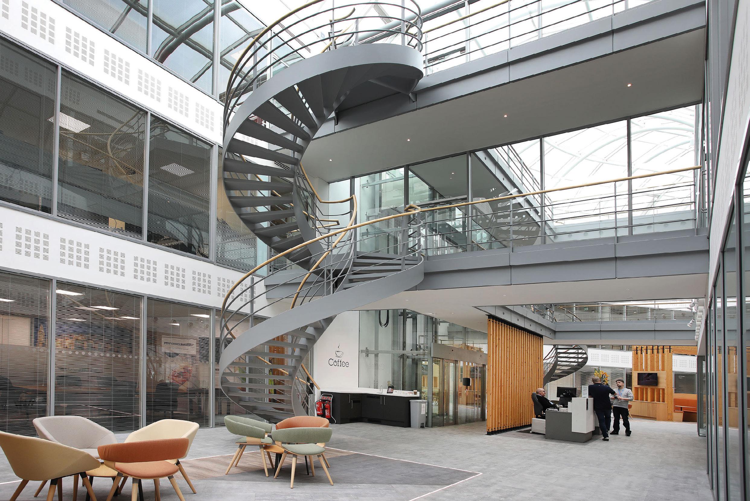
Air and water
source heat pumps have been installed in the retrofit of the 70,000ft2
From performance to practice
What is really limiting heat pump deployment? Tim Dwyer looks at barriers and opportunities after considering research and evidence presented at the government’s recent heat pump symposium
Heat pumps are no longer an emerging technology. Their thermodynamic performance is well established, their role in decarbonisation is widely accepted and, in many applications, they can deliver high efficiency and low operational carbon.
Yet deployment is well short of policy ambition. The question is no longer whether heat pumps work, but why they remain difficult to implement at scale.
A recent symposium* held in London, drawing on work from the International Energy Agency Heat Pump Technology Collaboration Programme and UK research initiatives, provides a useful lens through which to examine this gap between performance and practice.
From a diverse set of contributions, there is a consistent message. Barriers to adoption are no longer primarily thermodynamic; they lie in acoustic constraints, infrastructure limitations, system integration, user acceptance,
and the realities of different building types and ownership structures.2, 6
To decarbonise buildings, heat pump deployment must move from incremental growth to industrial scale. Installations worldwide are expected to rise from around 180 million in 2020 to 600 million by 2030. The UK ambition is for 19 million domestic installations by 2050 and a target of 600,000 per year by 2028.1
Current delivery falls well short, however. While recent targets implied around 200,000 UK installations in 2024, actual market activity has been significantly lower.1
This is not just a funding issue; it reflects a misalignment between technology, buildings, infrastructure, economics and client capability, particularly in smaller non-domestic projects where procurement routes are often informal.5
One constraint is noise. Evidence from UK installations indicates that a significant proportion of proposed
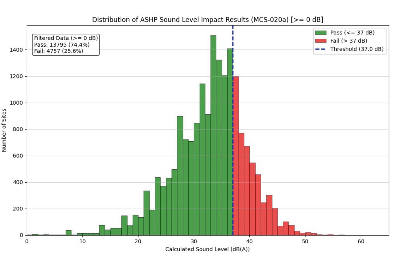
air source heat pump systems fail to meet planning guidance, often by small margins. As illustrated in Figure 1, differences of around 1dB can determine whether a scheme proceeds, creating a sensitive – and, effectively, binary – compliance regime.2
Prediction methods show variability of several decibels, while human perception is influenced by tonality, intermittency and context. As heat pump adoption increases, the cumulative effect of multiple units becomes more important.2
The practicalities of delivery are equally significant. Non-domestic buildings account for around 17% of UK energy use.3 The sector is highly heterogeneous, ranging from large, well-resourced estates to smaller buildings where retrofit decisions are less formalised. In this context, implementation often proves more challenging than the technology itself.
Early engagement with electricity networks is critical, as heat pump
Omnibus Building in Reigate, Surrey
installations can increase electrical demand significantly. If not addressed early, approval processes can become programme-critical constraints.
A detailed understanding of existing systems is essential. Issues such as plant location, water quality, hydraulic configuration and planning limits all influence feasibility. Where projects are tied to fixed delivery windows, delays in early-stage decision-making can determine whether schemes proceed.3
Heat pumps cannot always be treated as direct replacements for existing boilers. They form part of a system that must be integrated carefully. Pre-installation checks, including hydraulic separation where required, are often necessary to avoid inheriting legacy problems.
Commissioning is equally critical. Achieving design performance requires not only water balancing, but also heat balancing under realistic load conditions, ideally during winter operation.
Early monitoring data indicates that performance can vary from initial expectations, with commissioning and subsequent optimisation playing a key role in achieving design intent.3, 4
Existing building characteristics contribute to the challenge. Many were designed for higher-temperature systems, whereas heat pumps typically operate efficiently at lower flow temperatures. This mismatch can require emitter upgrades or use of higher-temperature systems. Cold and damp conditions can further affect performance through frosting and defrost cycles.1
Research is exploring ways to reduce inherent inefficiencies. One example is the quasi two-stage cycle that recovers energy normally lost during expansion and reuses it within the system. By reducing the effective compression lift, this can improve efficiency without additional mechanical complexity. It illustrates a trend towards reducing
internal losses rather than always relying on hardware.1
The relative cost of electricity and gas, often referred to as the spark gap, continues to influence viability. Where electricity prices are significantly higher, heat pumps must achieve high efficiencies to be cost-competitive. In some non-domestic applications, this has resulted in substantial carbon reductions being accompanied by increased operating costs, reinforcing the importance of performance, tariff structures and renewable integration.3
Integrated solutions
Combining heat pumps with onsite renewable generation, such as solar photovoltaics, can improve economics. Alternative delivery models, including power purchase agreements and energy-as-a-service, can also reduce upfront capital barriers. These approaches reflect a shift from viewing heat pumps as individual plant towards considering them as components within a broader energy strategy.3
User experience is central. Field trials, particularly of air-to-air systems, show
that acceptance depends on comfort, control and perceived performance as much as efficiency. Systems departing from conventional heating models may require behavioural adaptation.6
Emerging technologies may help address some constraints. Thermoacoustic and solid-state heat pumps offer alternative architectures that can reduce noise and enable deployment in more constrained settings. Flats and dense urban housing present particular challenges related to space, planning, ownership and disruption, which may require different system approaches. These technologies may expand the range of buildings that can be practically decarbonised.6
Subsurface systems, including ground source heat pumps and aquifer thermal energy storage, offer the potential for stable operation and seasonal balancing. However, recent field-scale studies show that subsurface behaviour can differ significantly from design assumptions, with factors such as fracture flow influencing heat distribution. This highlights the importance of site-specific data and ongoing validation. 4
Across the research landscape, a broader shift is evident. Innovation is increasingly focused on system-level performance and real-world operation rather than individual components. Monitoring and feedback are key, not only to verify performance, but also to support iterative optimisation and
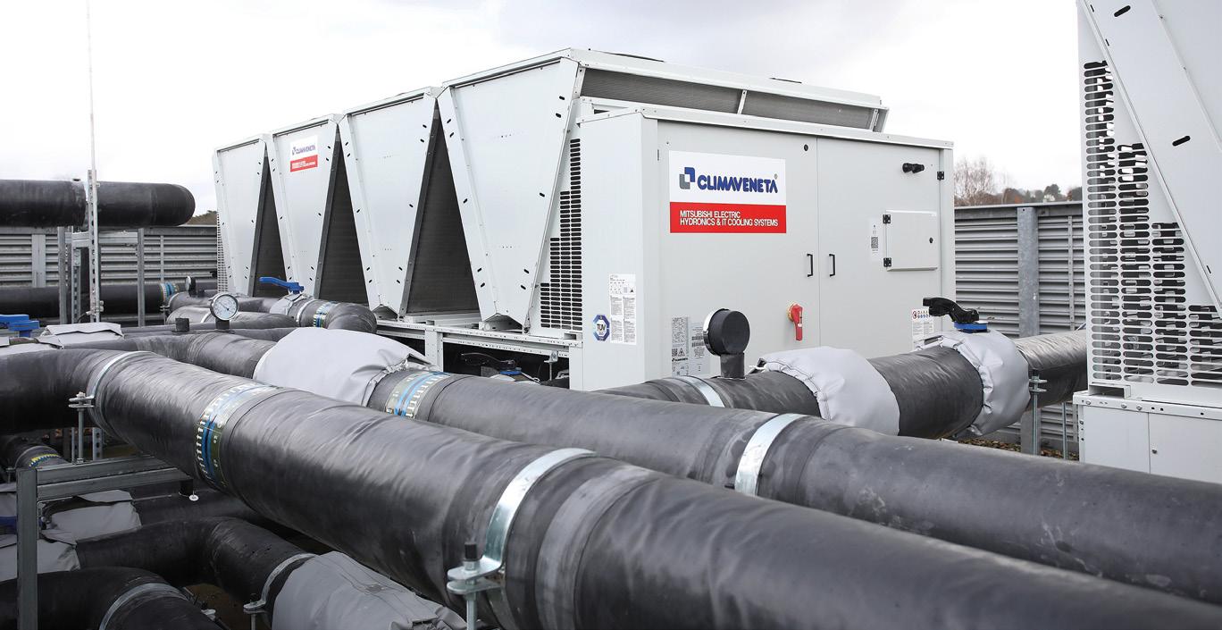
Mitsubishi Electric supplied a 4-pipe heat pump system providing heating and cooling at the Omnibus Building (see page 51)
Figure 1: Distribution of predicted ASHP sound levels against the MCS 020a planning guidance limit for domestic installations, showing that a significant proportion of proposed systems fail compliance, often by a very small margin.2






















build confidence in future deployment.3, 4
These insights suggest that the transition to low carbon heat requires a more comprehensive framework for decision-making. Efficiency and carbon must be considered alongside installability, acoustic impact, infrastructure constraints, user acceptance and economic viability. Different building types and contexts will require different solutions.
One response is the use of tools to support early-stage decision-making, particularly for clients unfamiliar with heat pumps (see panel, ‘Project 60’).
Building services engineering is shifting from optimising components to managing real-world systems in which technical performance, human factors and economic conditions must align. It is within this space, between performance and practice, that the success of heat pump deployment will be determined. l
References:
1 The Flexible Heat Pump Technology: A quasi two-stage cycle for enhanced efficiency and broad applications, University of Liverpool
2 Noise as a barrier to ASHP installations, Jack Harvie-Clark
3 Heat pump deployment in practice, Oakes/PHS (DESNZ–IEA Seminar)
4 Ground source heat pump retrofit: BGS Keyworth Living Lab; and UK Geoenergy Observatory and ATES Research
5 Project 60: Online interactive guidance tool, IEA Heat Pumping Technologies
6 Beyond compressors: heat pumps in transition, Dr Jonathan Siviter; and Air-to-air heat pump trials in UK homes, Energy Systems Catapult
Project 60: early-stage guidance for heat pump retrofit
An online tool from the IEA Heat Pumping Technologies programme provides simple decision support for nondomestic building owners considering heat pump retrofit.
Using a structured Q&A format, it helps users identify viable system options, rule out infeasible approaches and highlight missing information before engaging with suppliers. Outputs include shortlists of system types, supported by case studies and indicative comparisons of cost and carbon savings.
The tool is currently in testing and reflects the need to support early-stage decision-making in a sector where procurement routes are often informal and technical expertise may be limited.5
*The DESNZ/IEA Heat Pump Research Symposium explored current and emerging research within the IEA Heat Pumping Technologies Technology Collaboration Programme, and included experts from across industry, academia, research centres and government considering cutting-edge UK projects. For details see bit.ly/CJIEAHPT

Up to 15:1 turndown ratio, 40°C delta T and 90°C output for top up and back up heat demands. 15 MODELS 97 - 762kW COMBINE
5 MODELS 15 - 65kW



Using R290 natural refrigerant, the Tyneham 290HT achieves flow temperatures up to 75° C, improved efficiencies and low carbon heating.