
1. Machine & Part Reference Guide Page 3-4
2. Preshredder Installation & Safety Page 5
3. Preshredder Wiring Page 6
4. Preshredder Installing the Manual Pusher Page 7-8
5. Preshredder Powering Page 8
6. Preshredder Operation Page 9-10
7. Preshredder Maintenance Procedures Page 10-12
8. Know your Conveyor Page 13
9. Conveyor Installation Page 13-20
10. Conveyor Powering & Wiring Page 21
11. Conveyor (tracking the belt) Page 21-22
12. Conveyor Operation Page 22-23
13. Conveyor Maintenance Procedures Page 22-23
14. Know your Granulator Page 24
15. Granulator Installation Page 24-26
16. Granulator Powering & Wiring Page 26-28
17. Granulator Air Flow Page 28-29
18. Granulator Dust Collector Installation Page 29-30
19. Granulator Operation Page 31
18. Preparing Wires Page 31
19. Granulator Processing Adjustments (VFD, Blower, Vacuum) Page 32
20. Granulator Take Two Page 33
21.
22.
23. Granulator Sieve Page 36-37
24. Granulator Vibration Table Page 37-38
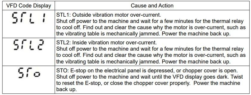
25. Troubleshooting FAQ's Page 38-40
26. Warranty Page 40-41
27. Replacement Parts Page 41
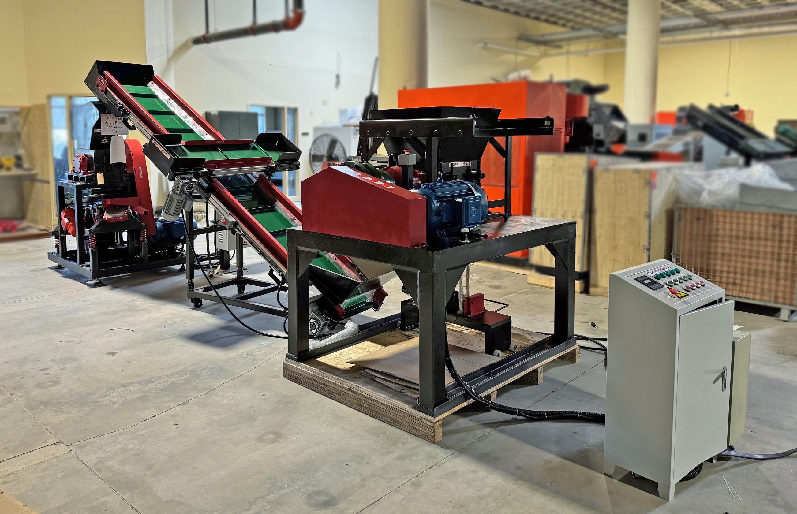
28. Machine Assembly Reference Images Page 41
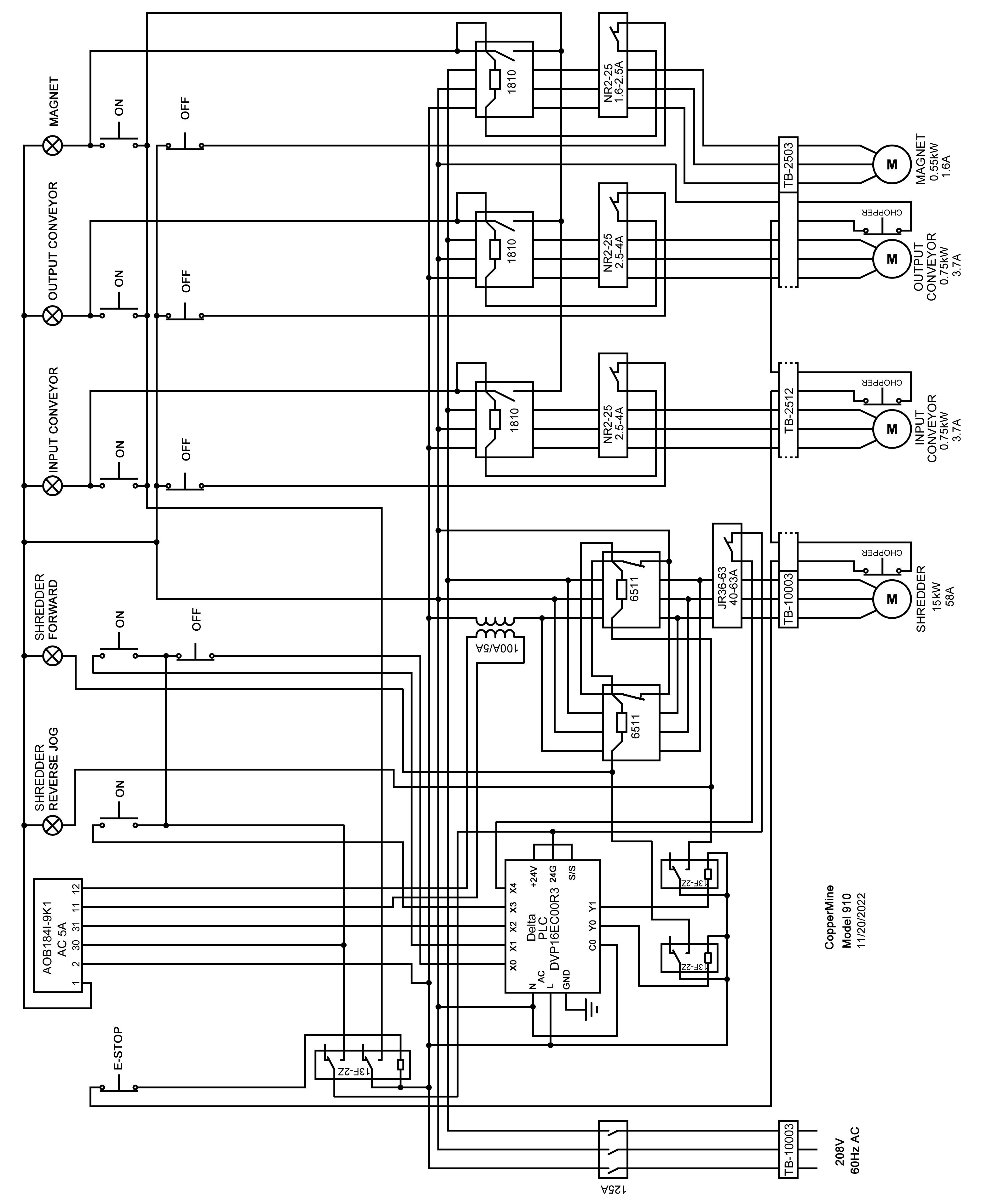
29. Electrical Schematic Page 42-43
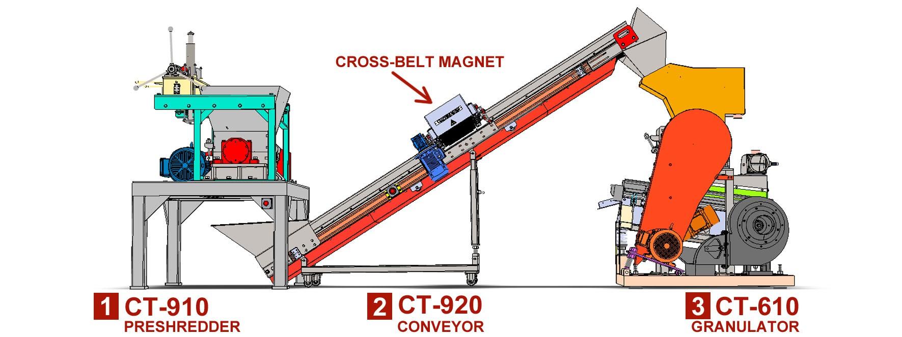
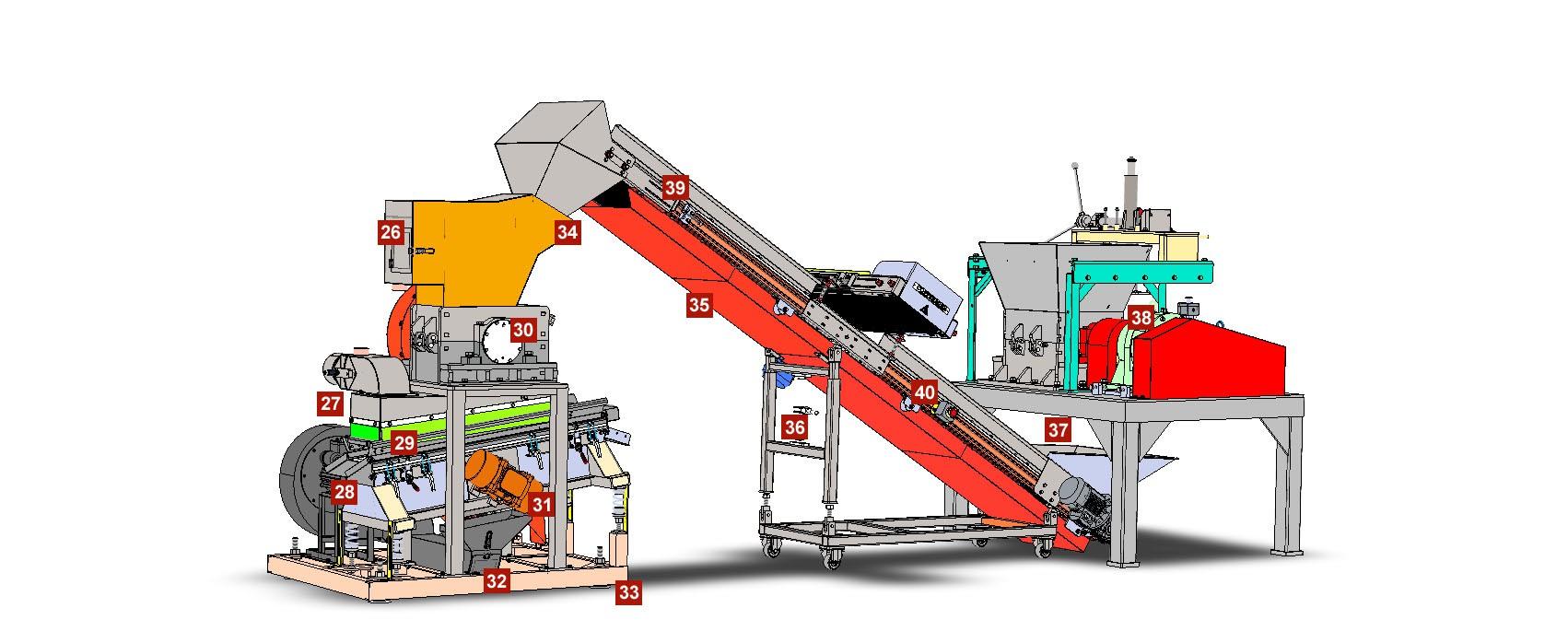
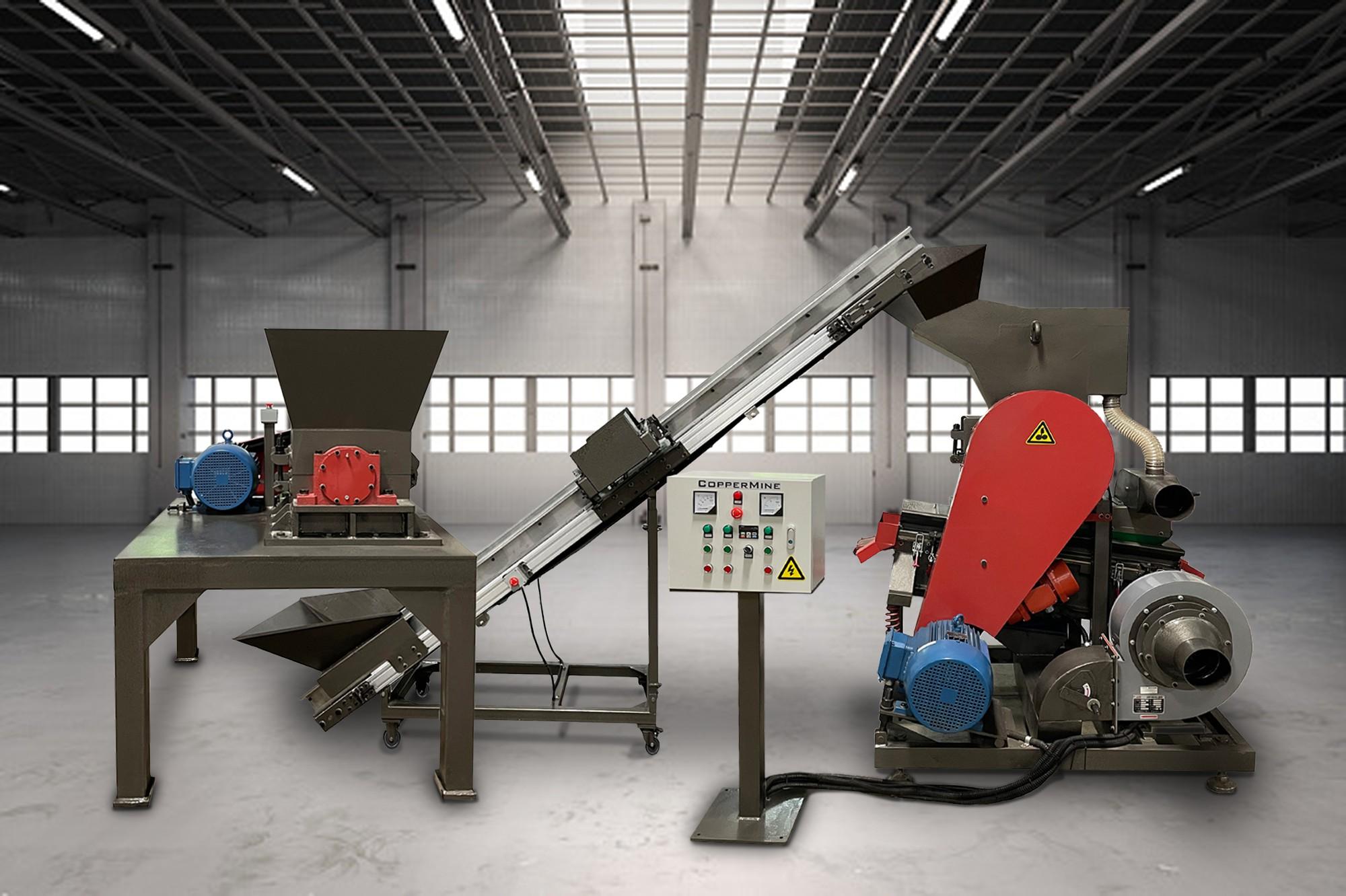
1. CT-910 Pre-Shredder
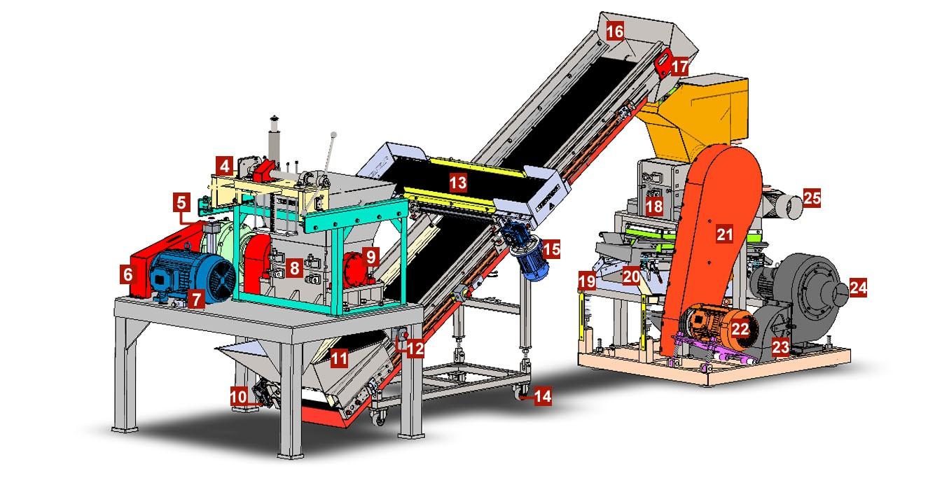
16. Discharge hopper 31. Vibration motor
2. CT-920 Output Conveyor 17. Forklift lifting handles 32. Blower pipe quick access door
3. CT-610 Granulator
4. Manual wire pusher
5. Emergency stop
6. Pre-Shredder belt cover
7. Pres-Shredder main motor
18. Granulator chopper opening 33. Adjustable rigging jacks
19. Pure copper outlet 34. Granulator feeding input
20. Take-Two outlet
Belt safety guard covers
21. Granulator belt cover 36. Conveyor adjustable height lever
22. Granulator main motor
Preshredder output
8. Pre-Shredder lid opening 23. Blower adjustment lever 38. Pre-Shredder gear box reducer
9. Pres-Shredder bearing housing 24. Blower hose connection pipe 39. Coveyor belt tension adjustment
10. Conveyor main motor
11. Feeding hopper
12. Emergency stop button
13. Cross-Belt magnet
14. Conveyor casters
15. Cross-Belt magnet main motor
25. Vacuum hose connection pipe 40. Conveyor belt rollers
26. Chopper lint quick access door
27. Vacuum adjustment lever
28. Insulation outlet
29. Vibration table quick access clamps
30. Granulator bearing housing
Product Specifications: L W H
CT-610 Granulator........................Dimensions: 70” x 46” x 66”
CT-910 Pre-Shredder...................Dimensions: 60" x 43" x 63"
CT-920 Output Conveyor.............Dimensions: 12' x 31” x 96”
AC-100 Dust Collector.................Dimensions: 44" x 24" x 64"
Full System Assembled...............Dimensions: 16' 10” x 10 ' x 7' 9”
Motor Specifications: Pre-Shredder
Main Motor 15HP (WEG): 200VAC, 60Hz, 42.4A, 11kW, 1770 r/min
Optional Upgrade 20HP (WEG): 200VAC, 60Hz, 58.2A, 15kW, 1770r/min
Conveyor
Main Motor: 200VAC, 60Hz, 3.49A, 0.75kW, 1700 r/min
Cross-Belt Motor: 200VAC, 60Hz, 2.62A, 0.55kW, 1700r/min
Granulator
Main Motor 15HP (WEG): 200VAC, 60Hz, 42.4A, 11kW, 1770 r/min
Vibration Motor (x2): 200VAC, 60Hz, 1.45A, 0.15kW, 1800 r/min
Blower Motor: 200VAC, 60Hz, 6.93A, 1.5kW, 1750 r/min
Vacuum Motor: 200VAC, 60Hz, 3.38A, 1.1kW, 3360 r/min
Weight: 1,900 lbs
Weight: 1,700 lbs
Weight: 500 lbs
Weight: 260 lbs
Make yourself familiar with the equipment structure, the installation, operation and maintenance procedures before installing and operating this equipment.
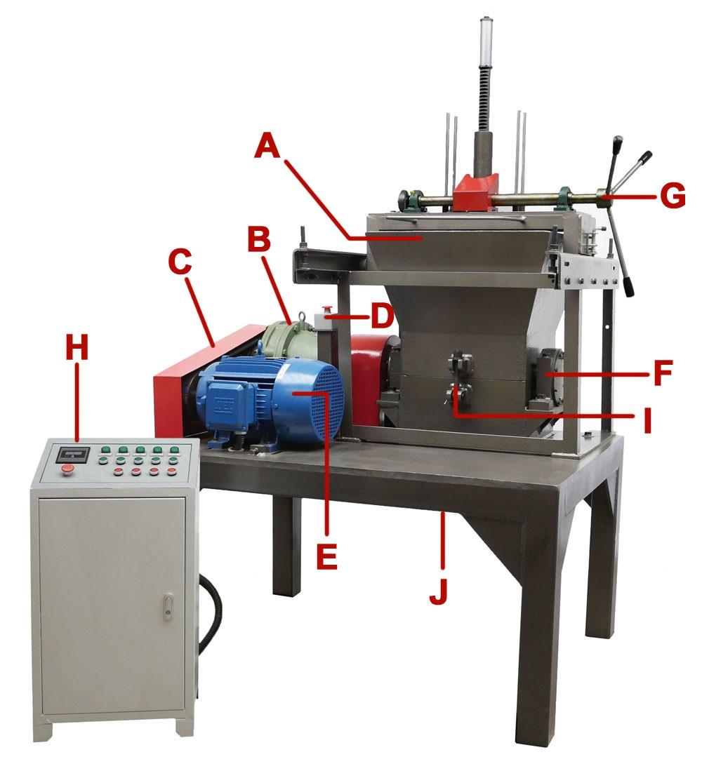
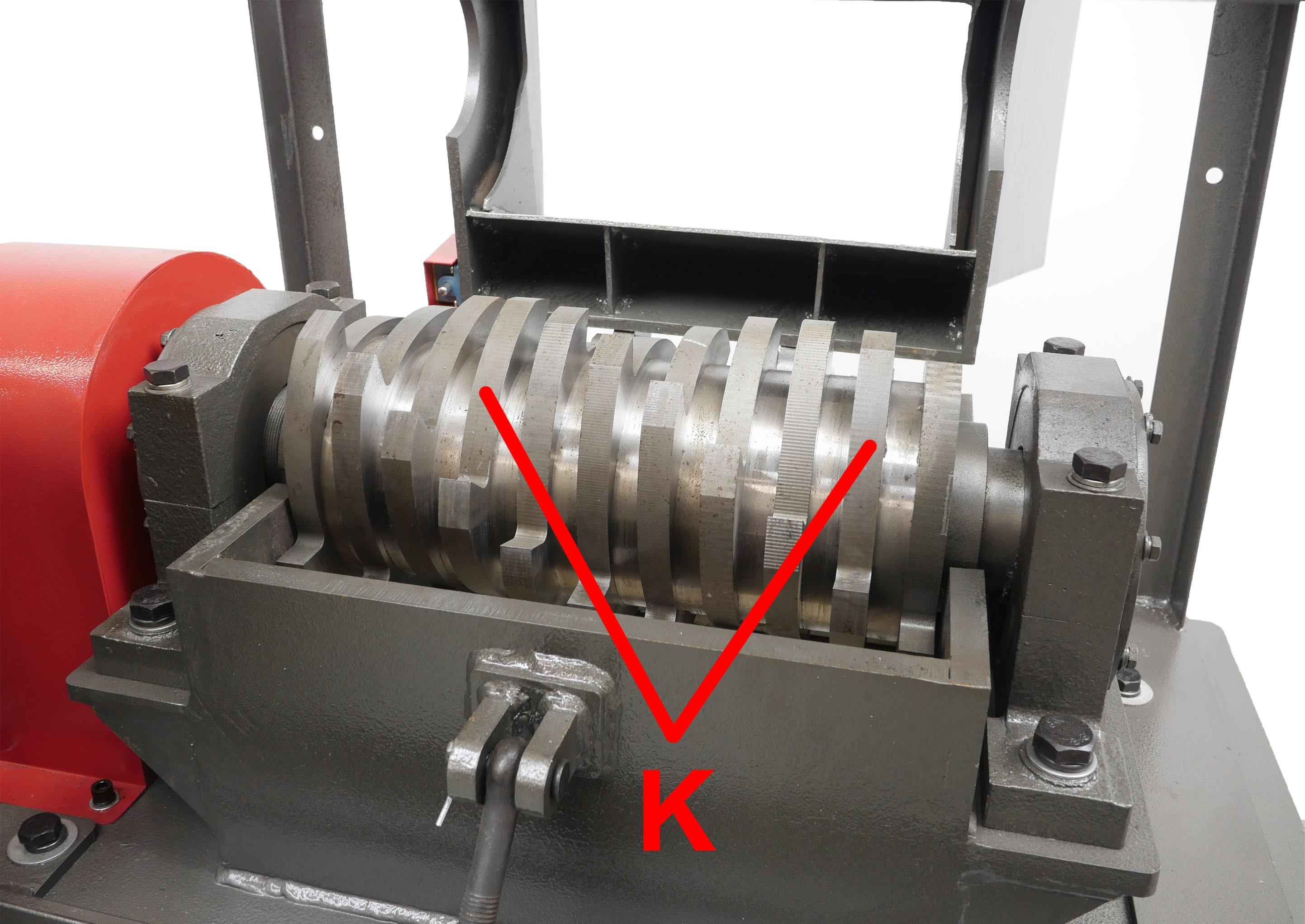
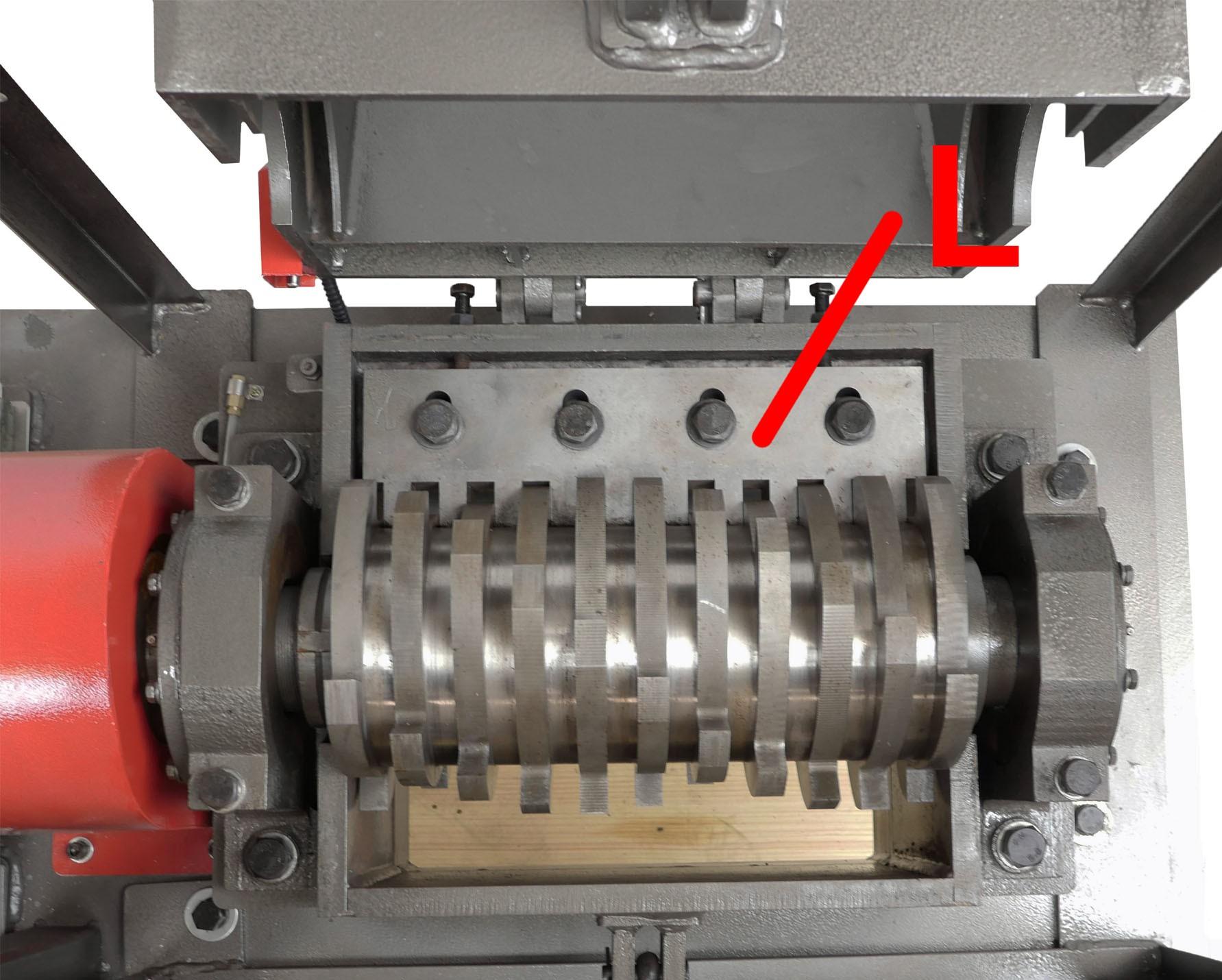
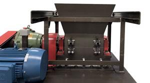
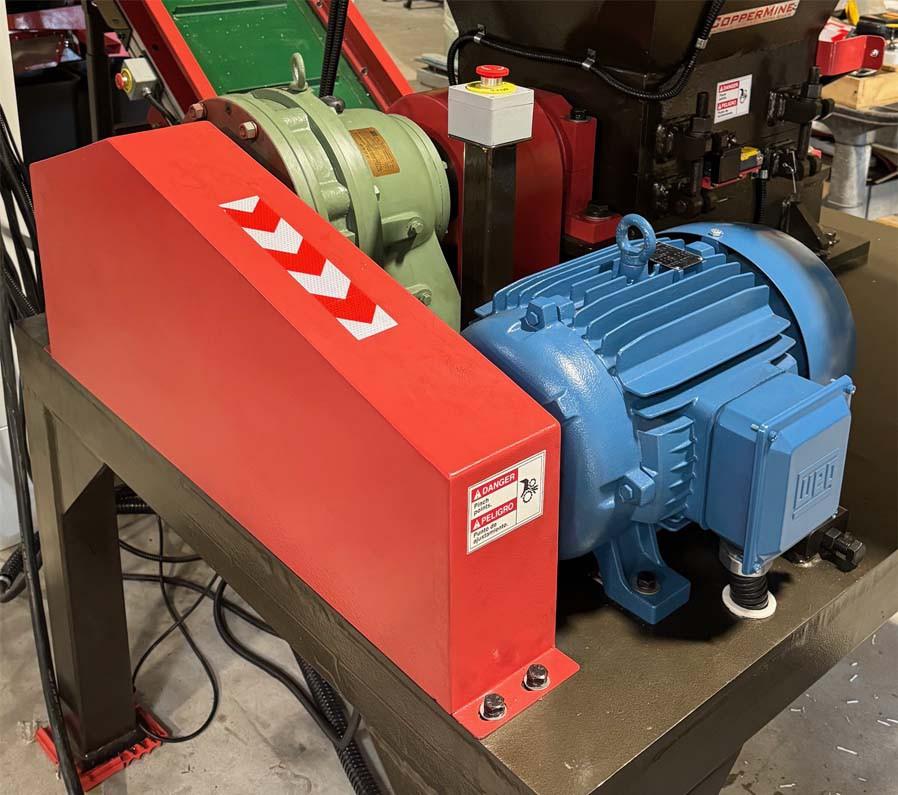
A: Pre-Shredder Opening; B: Gear Box; C: Belt Cover; D: E-Stop; E: Motor; F: Bearing Housing; G: Manual Wire Pusher; H: Electrical Panel; I: Preshredder Chopper Opening; J: Outlet; K: Rotating Blades; L: Stationary Blade
• Read all information in this manual before proceeding.
• Never stick any body parts into the shredding area (above or underneath the blades) when the machine is powered on.
• DO NOT stand on the machine chassis while the machine is running.
• Always wear eye, hearing, hand protections
• Keep bystanders away from equipment when running the machine.
• Disconnect the equipment from the main power before performing any inspection or maintenance.
NOTE: Before installation, observe through the feeding hopper how the blades are arranged, paying special attention to the clearance between stationary and rotating blades, while they are still new and sharp. This will help during future blade adjustment.
• The pre-shredder is designed to be used indoors.
• Choose a location that is well lit, flat, level, stable, and close to electrical power.
• It is NOT necessary to bolt the pre-shredder down to the floor. You can use anti vibration pads under the base of each foot.
• The location should allow noise level produced by the pre-shredder.
• A licensed electrician must be used to wire the pre-shredder.
• Inspect the wires to ensure that they are still well connected and are free of any abrasion to the outside insulation.
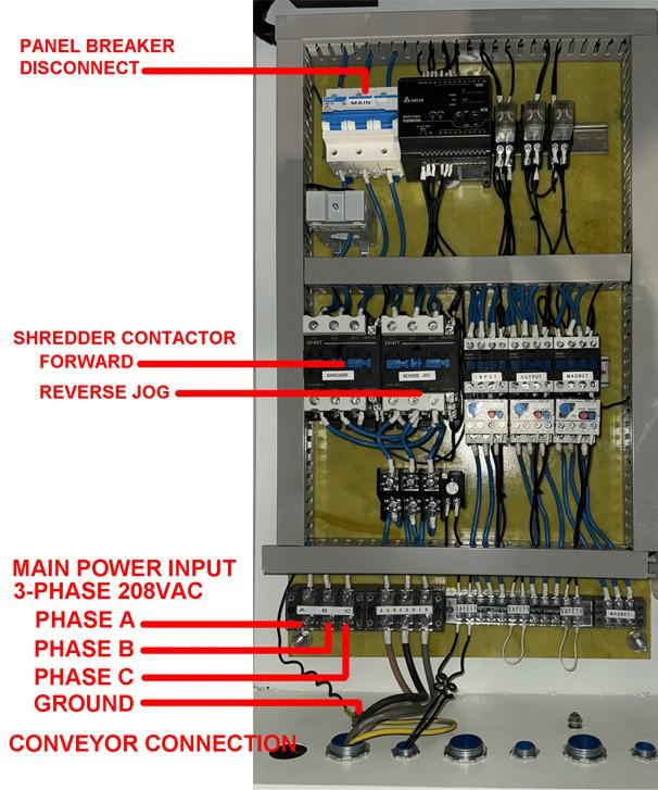
• Wire 3-Phase 208VAC main power to the control panel using 4 AWG wires or thicker. The main power ground should be connected to the grounding spot in the electrical cabinet. The machine chassis must also be grounded separately using an 6 AWG wire or thicker.
• Please refer to the wiring diagram attached at the end of this manual for wiring.
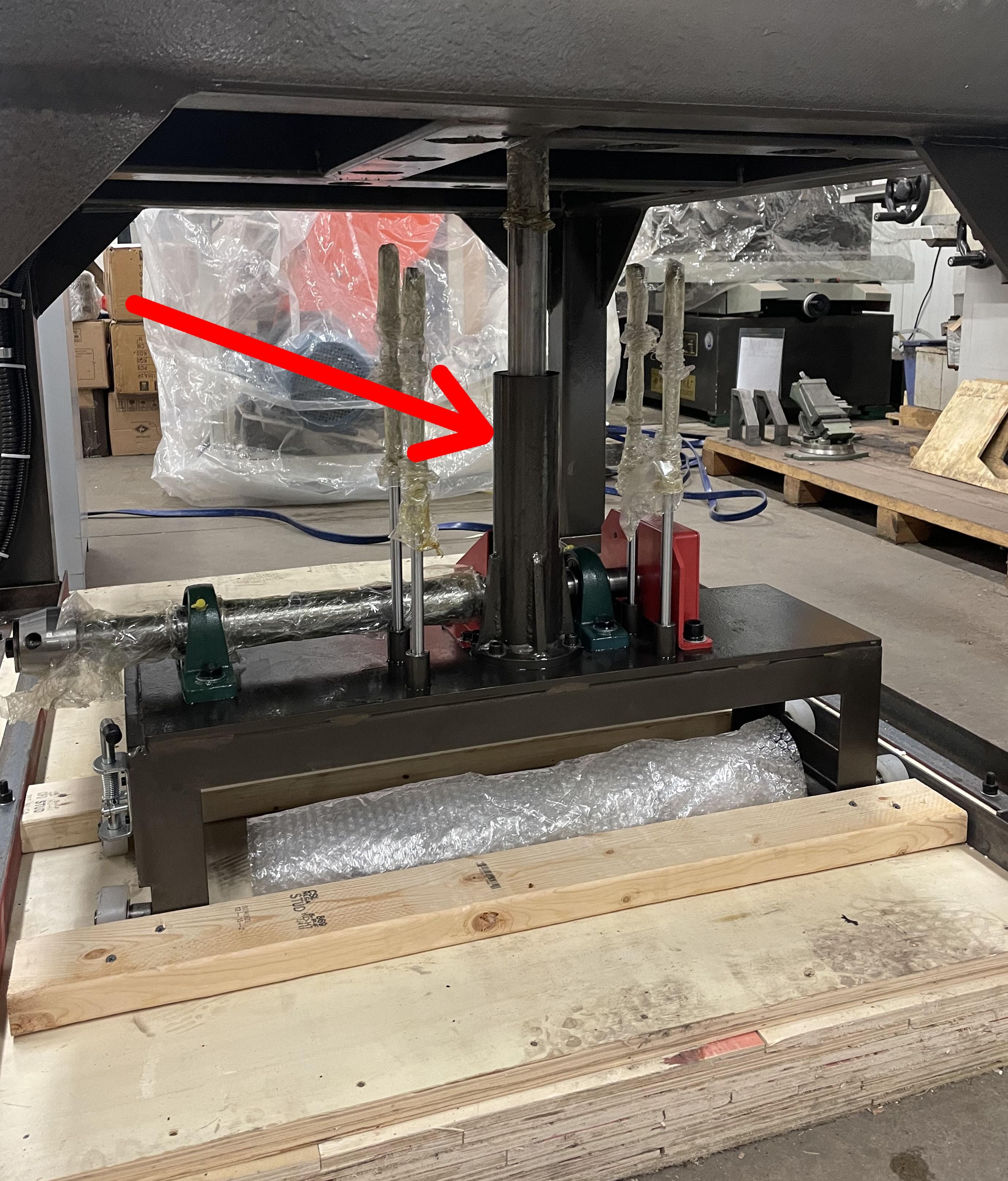
• The manual pusher frame is already preinstalled for you.
• At the bottom of the crate you will find the manual pusher, please remove this carefully being cautious not to bend the rods.
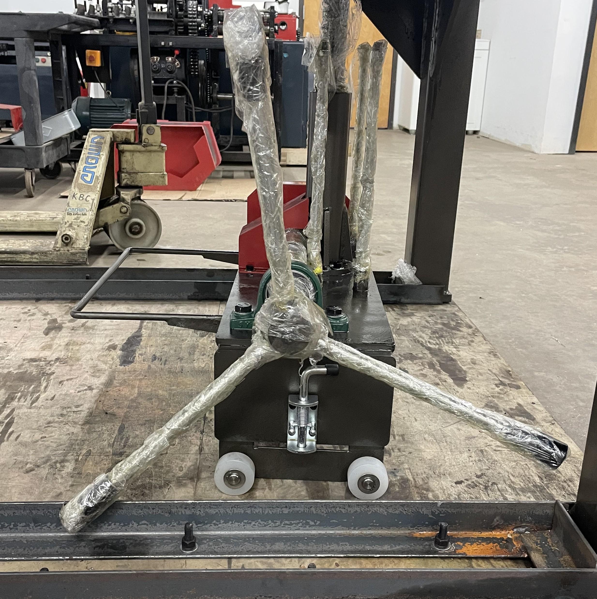
• Install the pusher wheel levers as shown.
• Locate and remove the bolts zip tied to the pusher frame.
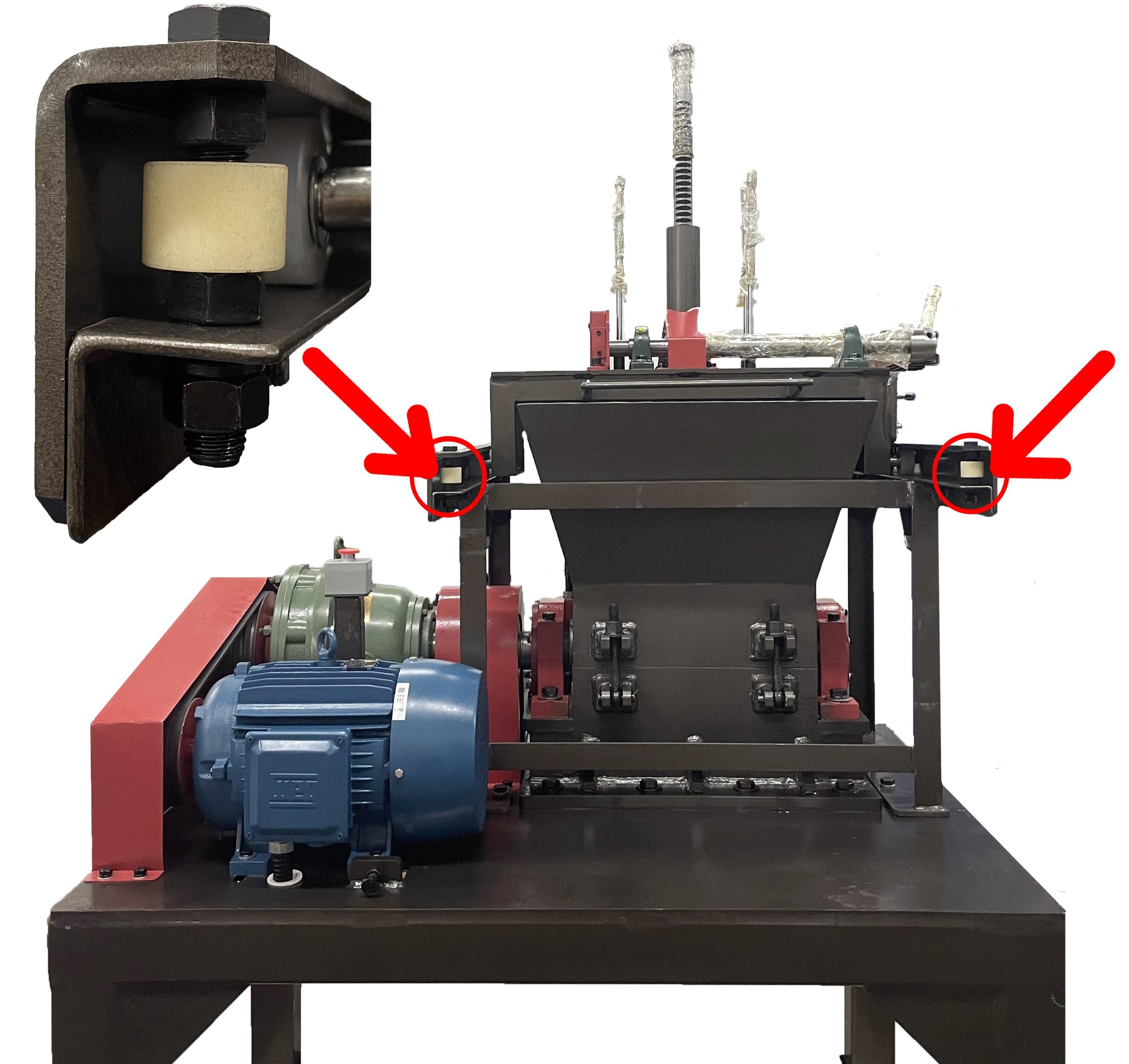
• Using (2) persons, or machinery lift the manual pusher and install it into the frame as shown below. The locking lever and crank wheel should be to the right.
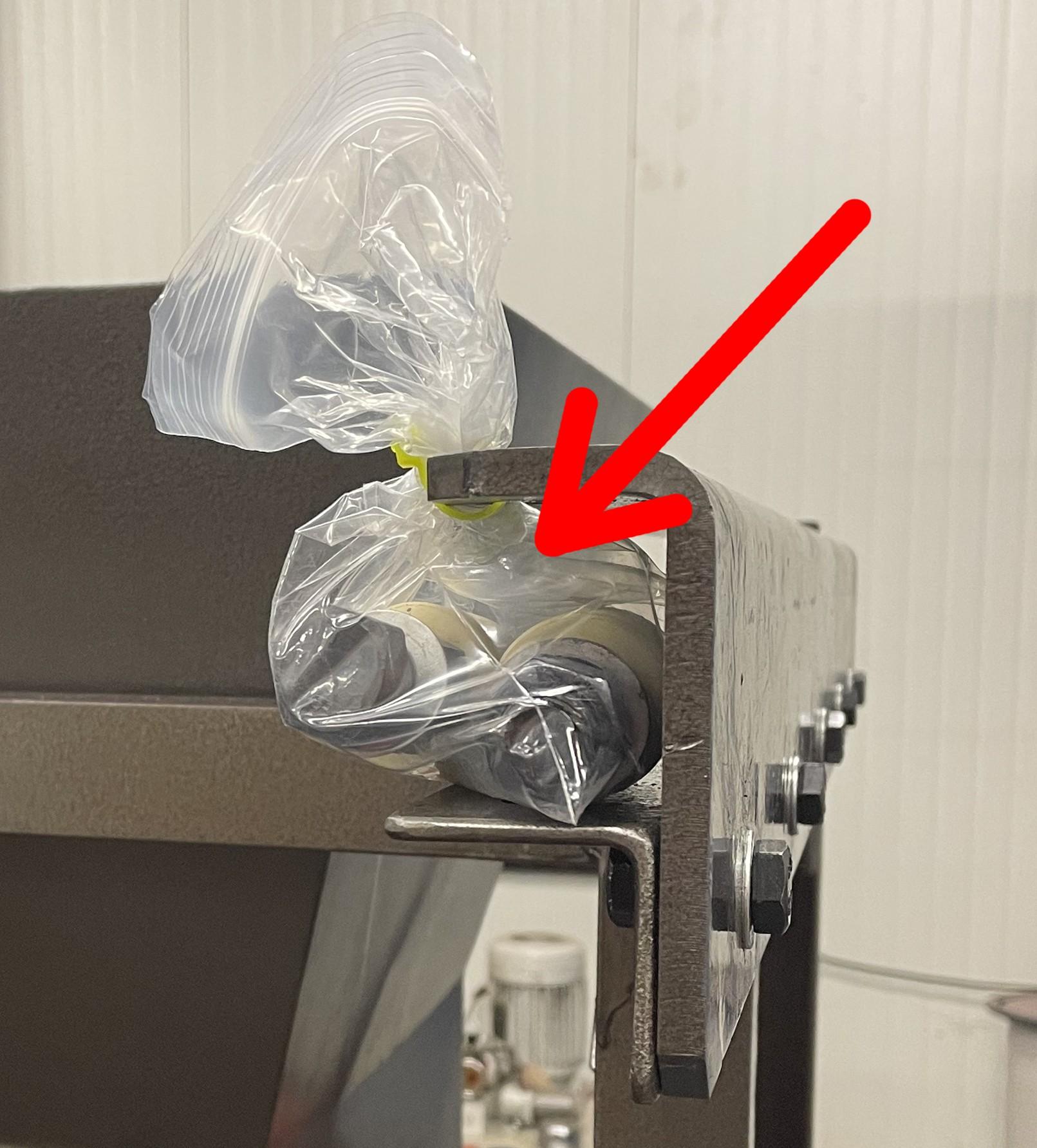
• IMPORTANT: After the pusher is in place, install the safety bolts into place to keep the pusher from rolling out of the track. Failure to install can result in injury or damaging your machine!
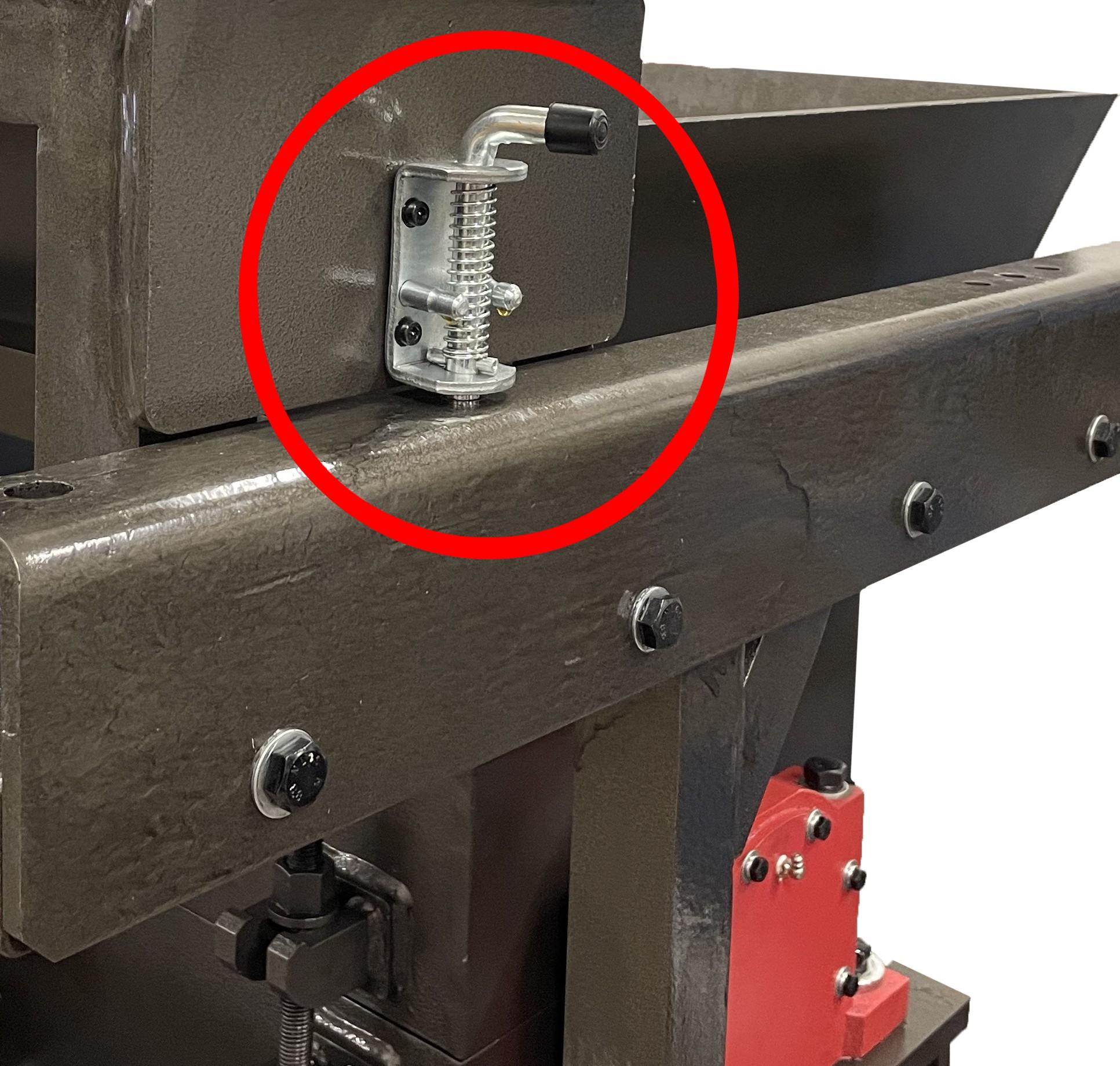
• Use the locking lever to change and fix the position of the pusher.
• Use the hand crank wheel to assist in pushing material down, DO NOT over exert the force as it can cause additional stress to the motor, or jam your machine.
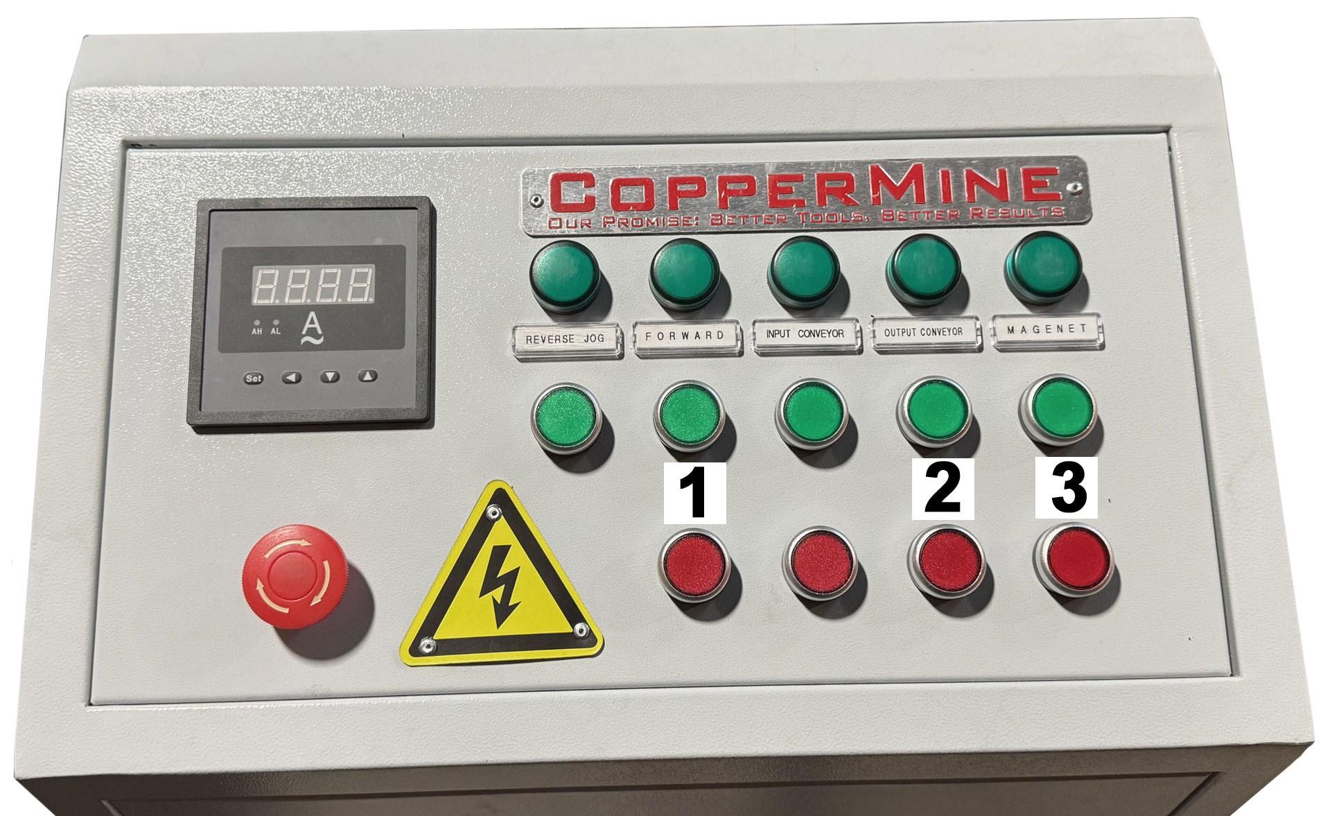
& 920 Panel
Panel
• Before powering on the machine, check to make sure all moving parts (blades, conveyor, motor, etc.) are clear from debris.
• Flip all of the breakers in the electrical cabinet ON.
• Power on the main breaker from the electrical panel making sure the line voltage meter is reading within (208 – 220VAC) range. Close and lock the cabinet.
• Power on the pre-shredder from the control panel making sure the current meter reads within range. (The current should not exceed 46A during operation.)
• IMPORTANT: Make sure the rotation of the belts are following the direction shown on the belt cover. If the rotation is wrong, swap any two phases at the main power connection. This will change the motor direction.
• Preparing the Wires
◦ Remove all connectors, clips, hardware, etc from the wires.
◦ Sort wires based on types. This helps to simplify adjustment and improve copper grade when using the granulator.
◦ Wires should be dry and oil-free.
• Feeding the Pre-Shredder
◦ Throw (or use conveyor if equipped to feed) wires into the feeding hopper. NEVER STICK ANY BODY PARTS INTO THE FEEDING HOPPER. Use the manual pusher (if equipped) to push the material into the chopper.
◦ Wires may get stuck in the feeding hopper if overfed. Try to feed wires into the preshredder in a smooth and uniform fashion to reduce stress on the machine.
• Automatic Reverse Feature (DO NOT REACH INTO THE MACHINE IF IT JAMS!)
◦ In the event that the machine is overloaded or jams, there is an automatic reverse.
◦ The machine will power off for 8 to 10 seconds. The machine will automatically switch to reverse and run for 4 seconds, then power off for another 8 to 10 seconds. Finally the machine will start back up and run in the forward direction. You can resume using the machine if the jam has cleared.
◦ If the jam is not resolved after three cycles please disconnect the machine from power and contact CopperMine.
◦ To override the automatic reverse press the emergency stop button.
• Turning OFF the Pre-Shredder
◦ Stop feeding wires and wait until the conveyor (if equipped) feeding the preshredder is clear.
◦ Wait until the shredder empties itself (no more wires remain in the hopper). Failure to do so may cause the pre-shredder to jam at the next start-up.
◦ Turn off pre-shredder.
◦ Turn off the main breaker in the electrical cabinet at the end of the work day.
• Emergency Stop
◦ In case of an emergency, press the emergency button to shut down the full system.
◦ There are multiple E-Stop buttons throughout the system take time to locate them and familiarize yourself with their locations.
◦ Disconnect the power to the pre-shredder and manually clean out any wires that remain in the hopper, before restart.
Maintenance
• Safety Precautions
◦ Any service or maintenance should only be performed by qualified personnel.
◦ Do not rotate the shredding rotor or pulleys with bare hands.
◦ All power to the equipment should be unplugged and measures must be taken to prevent accidental re-connection to the power during maintenance
• Shaft Coupling
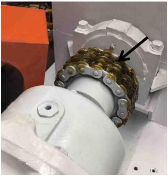
◦ The gear box and blade shaft are connected by a roller chain shaft coupling. The shaft coupling should remain well lubricated. Apply a high quality roller bearing grease of medium consistency, such as Mobilux EP2, every 100 hours of use or every month, whichever comes first.
• Gear Box
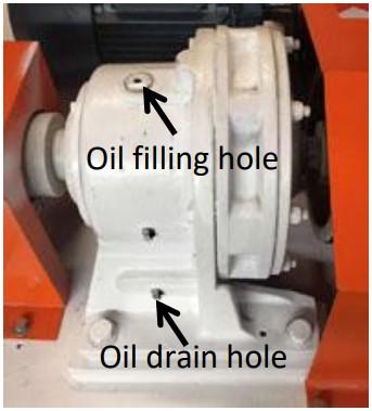
◦ The threaded cap located on top of the gear box is for oil filling and venting. A plastic breather has been installed to prevent contamination.
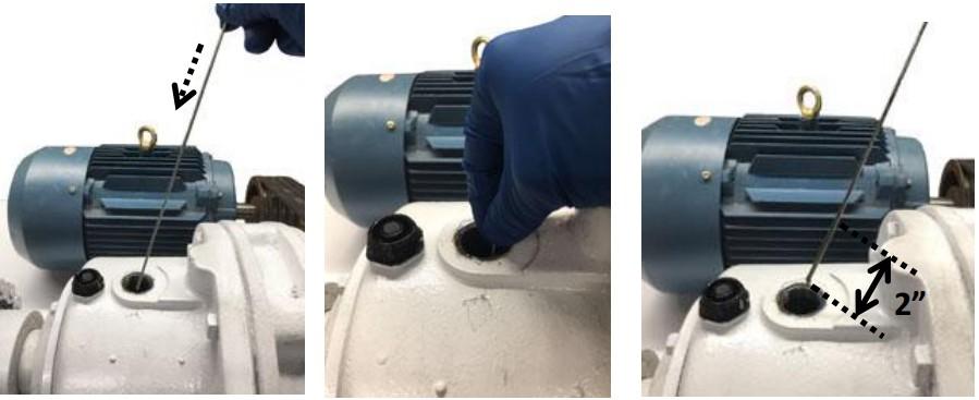
◦ Inspect the oil in the gear box every 100 hours of use or every month, whichever comes first. Insert a clean 9-inch-long stick through the top opening until its tail end
is flush with the opening. Pull out and observe oil residue on the stick. Oil should be visible on the tip of the stick but should not exceed 2” from the tip.
• The gear box needs to be drained at its first oil change or top-off, in order to avoid contamination of different oil brands. After that, top-off the gear box whenever the oil level is low, or change the oil when it is dirty or is at its end of life.
• Oil in the gear box should be changed every 2000 hours of use or every 12 months, whichever comes first. Approximately 0.5 gallon of Shell brand, or equivalent, oil is needed for each oil change. Choose the proper oil type based on the room temperature near the equipment.

• Due to its extreme working condition, minor oil leaks from the gear box is normal. Oil residue should remain within 10-inch distance from the footprint of the gear box. Frequent oil level checks are required to ensure proper internal lubrication of the gear
• Insufficient lubrication is the main reason for premature gear box failures, which is NOT covered by the warranty.
• Lubricating the Bearings
◦ The main bearings work under brutal conditions and should be lubricated once every 20 to 40 hours of use.
◦ An abnormal temperature rise on the bearing indicates poor lubrication or damaged blades. Stop the pre-shredder immediately and resolve the issue.
◦ Insufficient lubrication is the main reason for premature bearing failures, which is NOT covered by the warranty.
◦ Use high quality lithium-based high-temperature extreme-pressure grease, such as Mobil Delvac™ Xtreme Grease or equivalent.
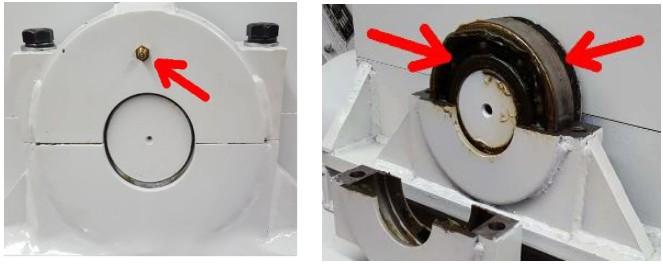
◦ Use a grease gun or remove the top bearing cover. Apply sufficient grease into the bearing.
• Blade Adjustment
◦ The blades are made of durable alloy steel and should last a long time under normal use.
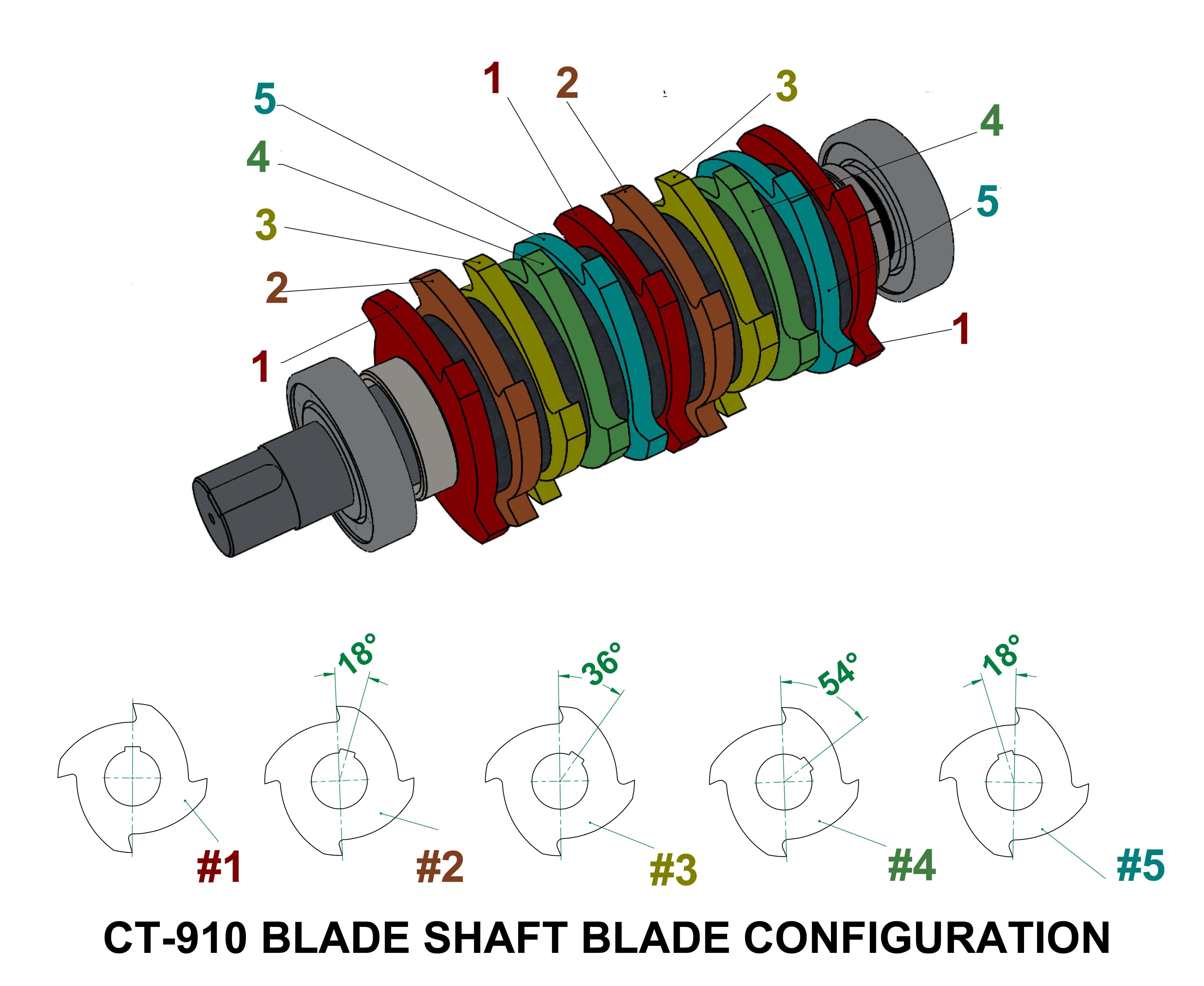
◦ When wires are not cut properly inspect the gap between the stationary blade and the rotating blades. If the gap needs to be reduced, loosen the bolts and nudge the stationary blade towards the rotating blades to improve the shredding performance.
Specifications
• Processing speed: approx. 1,000 Lbs insulated wire per hour
• Power requirement: 208 - 220VAC, 60Hz, 3-Phase, up to 50Amp each phase
◦ 20HP 208-220VAC, 60Hz, 3-Phase 58A
• Power consumption: up to 11 kW (optional 15kW)
• Main motor
• 208VAC, 60Hz, 3-Phase
• Delta connection, 15HP(11kW), 1740 rpm (optional 20HP(15kW))
• Number of Rotating blades: 21
• Number of Stationary blades: 1
• Throat Width: 16-inch
(Specifications subject to change without notice)
Make yourself familiar with the equipment structure, the installation, operation and maintenance procedures before installing and operating this equipment.
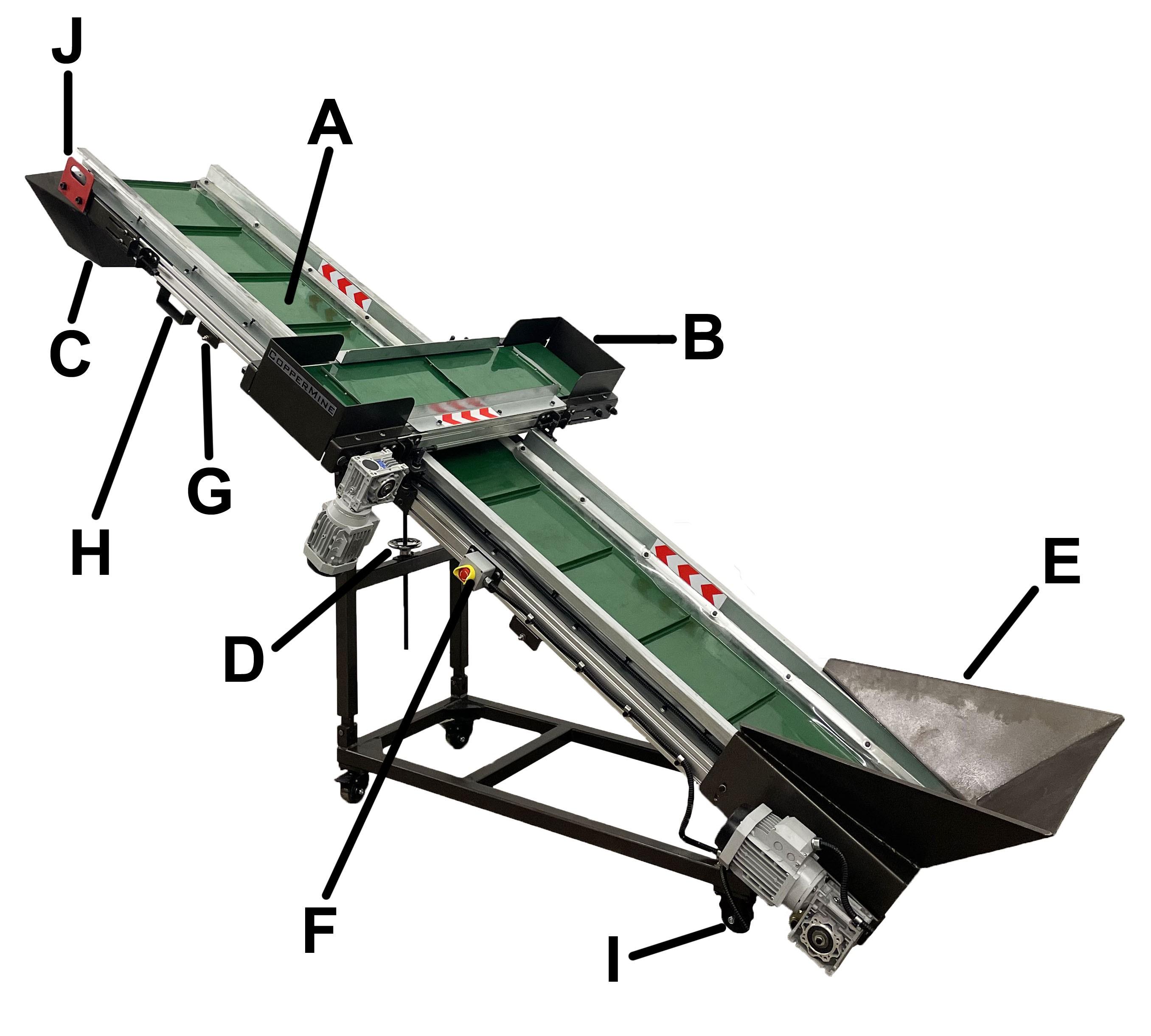
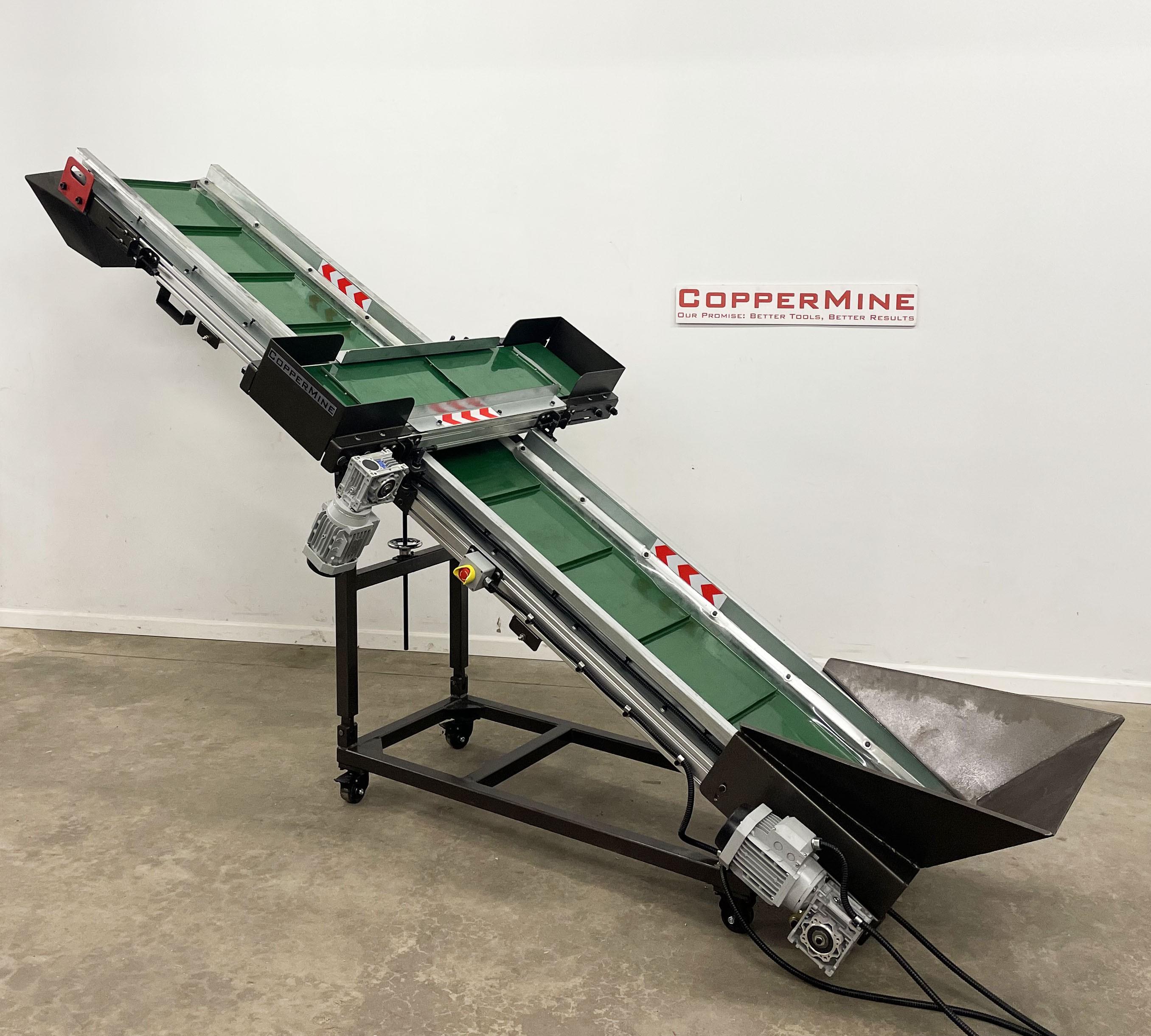
A: Conveyor Belt; B: Cross-Belt Magnet; C: Discharge Hopper; D: Hand Wheel Crank; E: Feeding Hopper; F: Emergency Stop Button; G: Belt Rollers; H: Forklift Handles; I: Caster Wheels; J: Lifting Handles
Installation
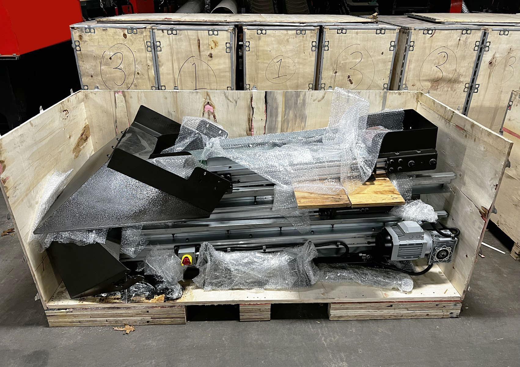
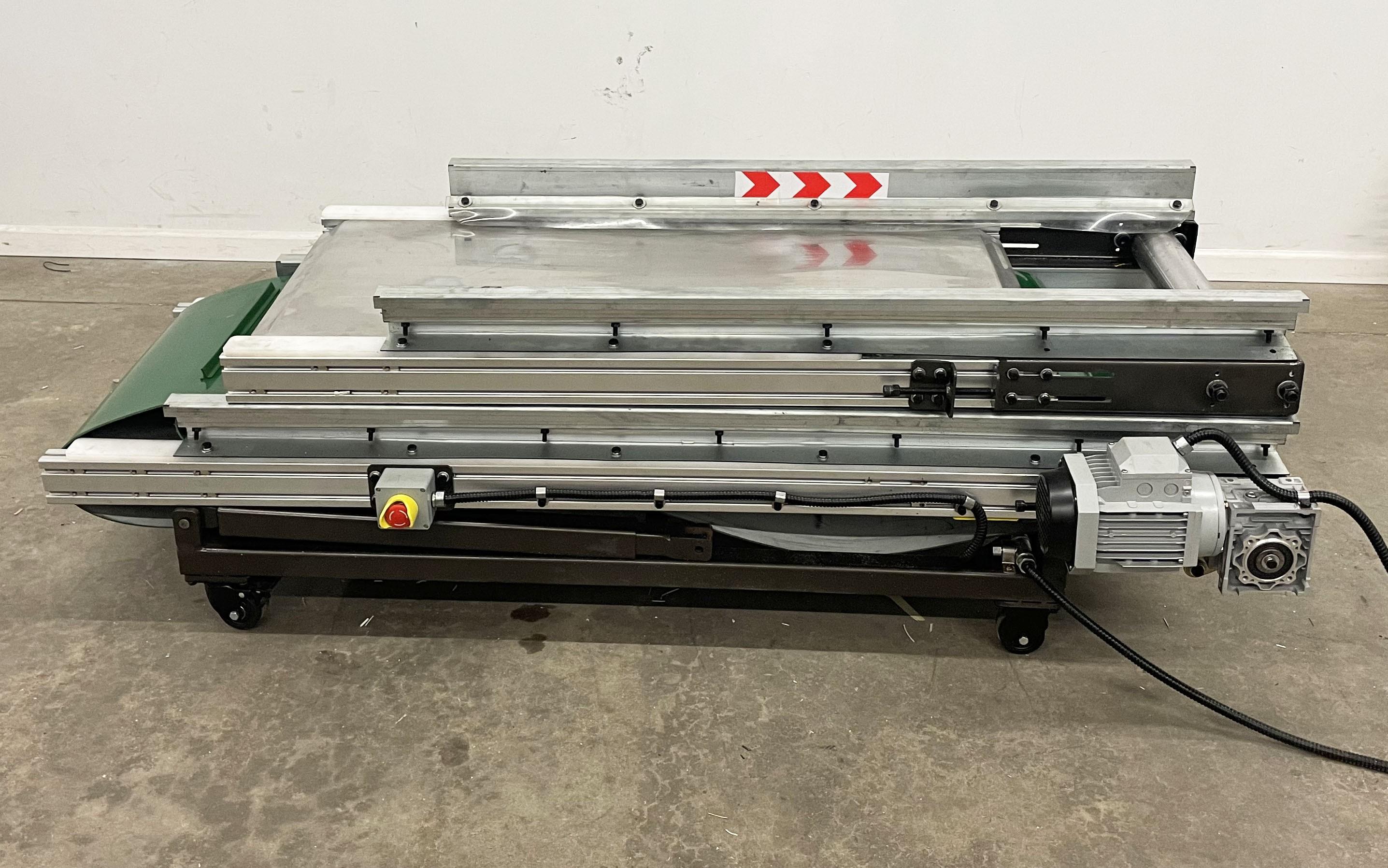
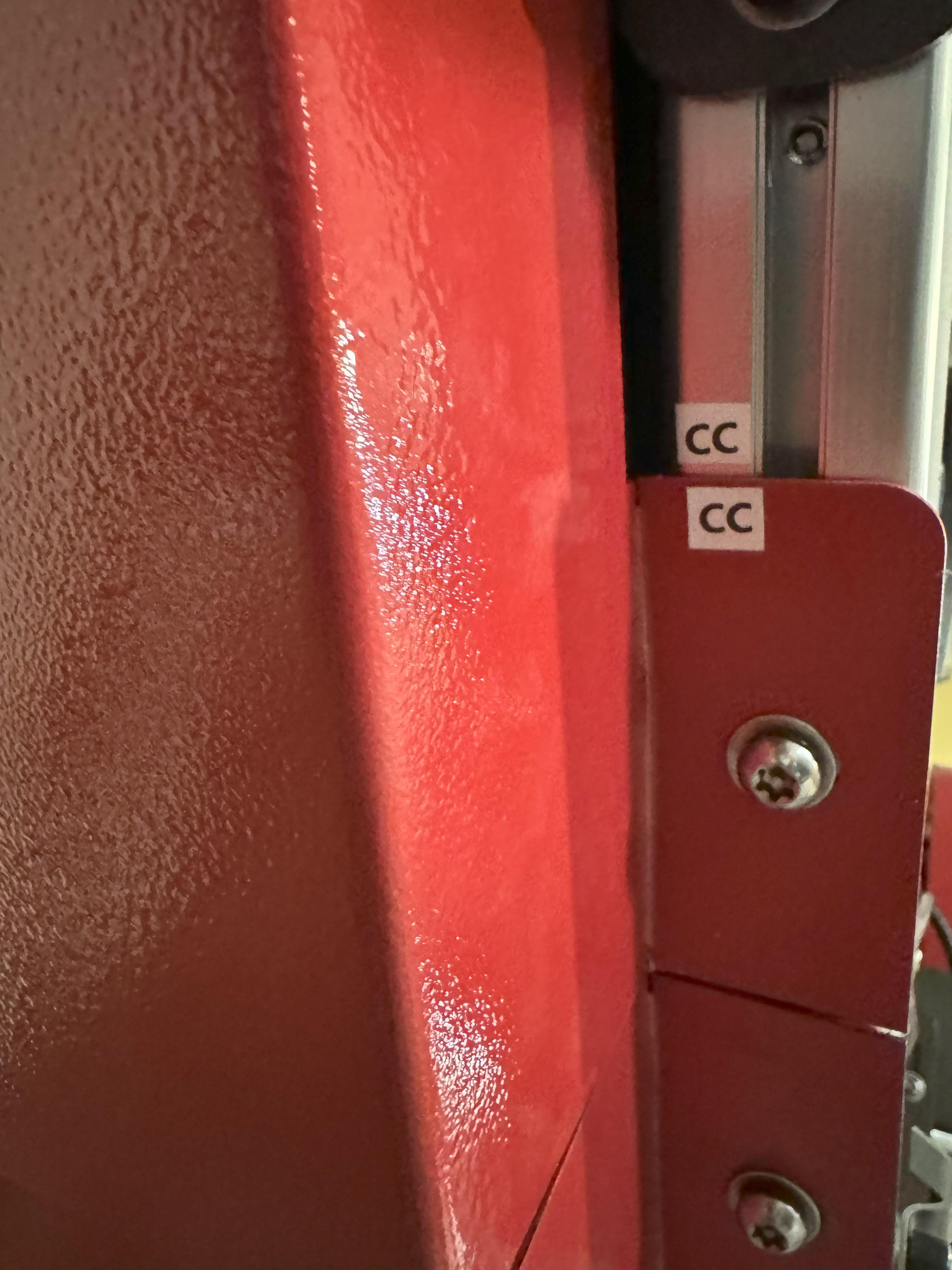
In order to minimize shipping damages, the conveyor is shipped in a collapsed position with some parts removed. Use the following steps to assemble the conveyor. Identification marks and numbers have been put on the machine to facilitate re-assembly.
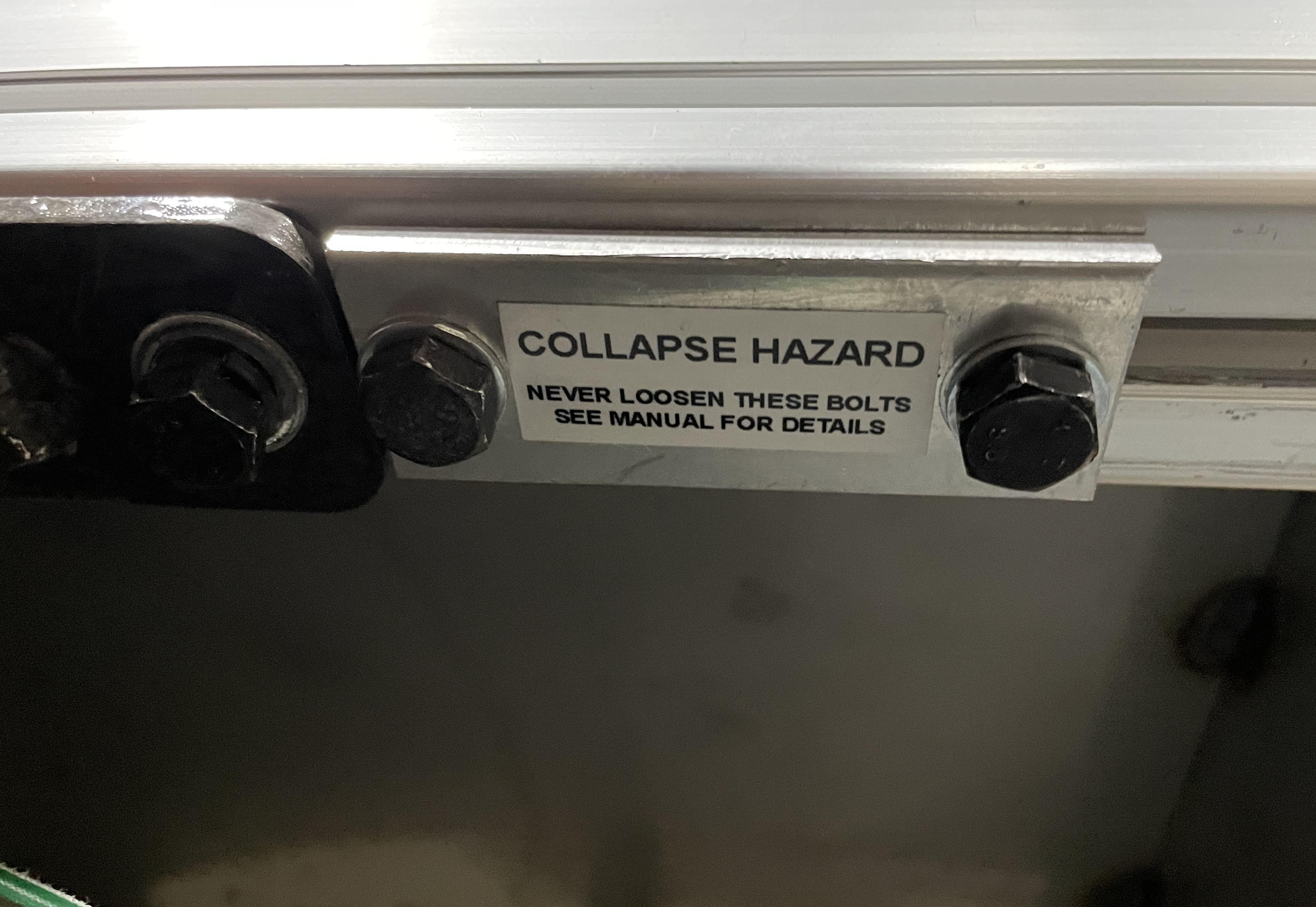
Assembly SAFTEY BRAKETS! THESE PARTS ARE PREINSTALLED. (THESE PARTS SHOULD NEVER BE LOOSENED OR REMOVED AFTER ASSEMBLY. THE CONVEYOR CAN COLLAPSE.)
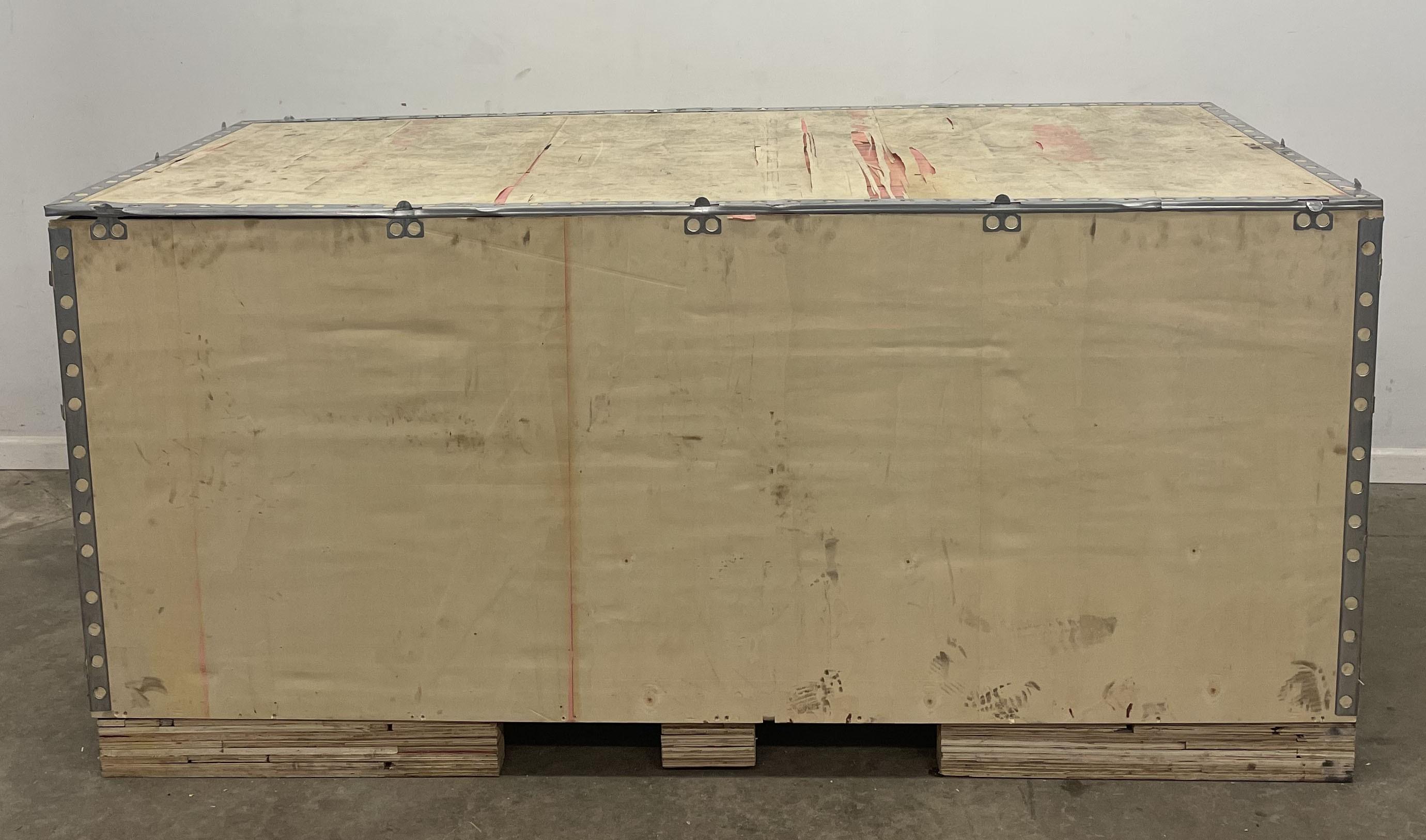
1. Open the crate
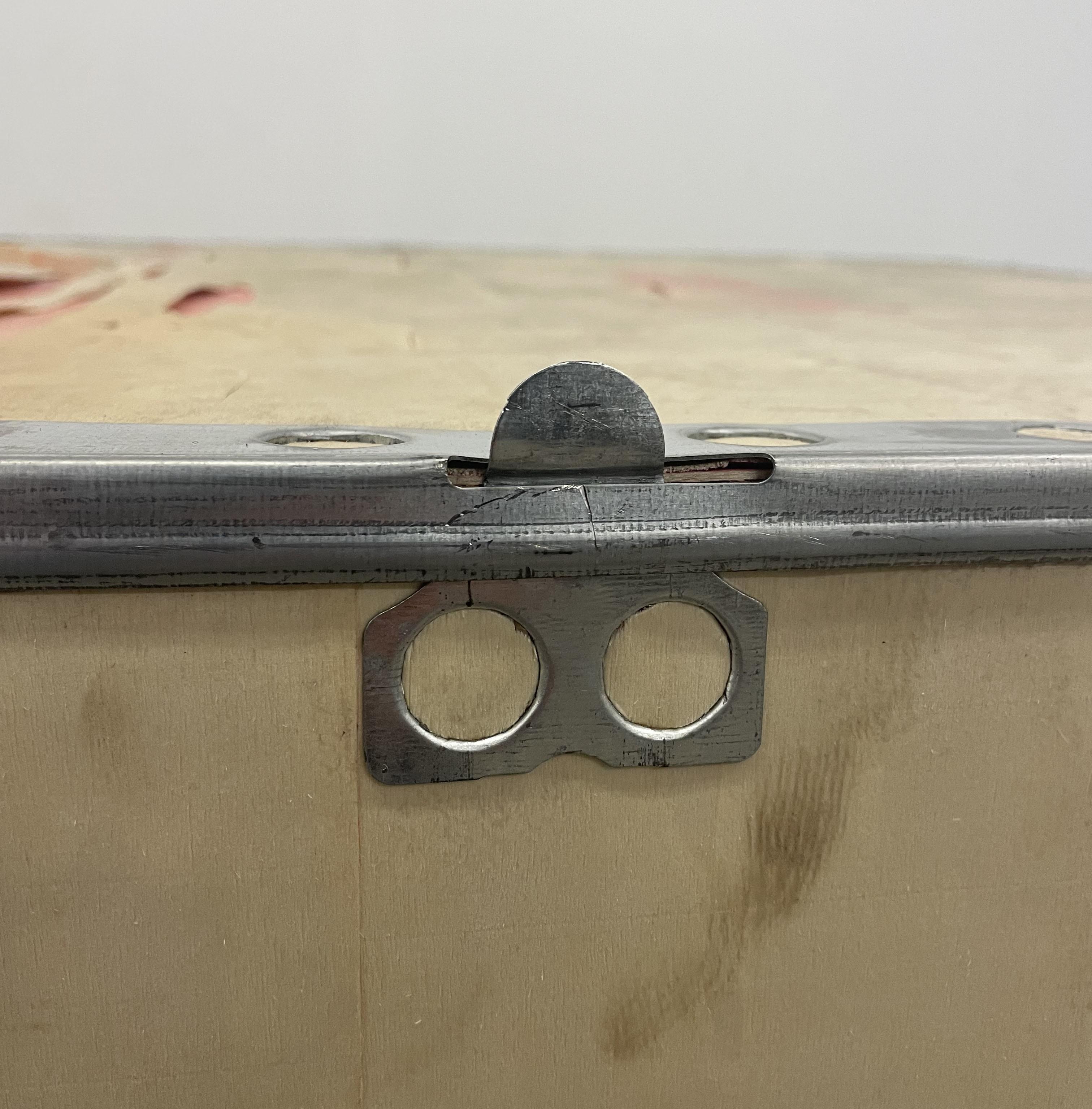
Bend the tabs on the crate to remove the panels. Cut the band straps securing the machine to the crate.
2. Remove loose parts
Locate the parts box. Remove the discharge hopper, the feeding hopper, and any other loose part located in or around the machine.
3. Remove the Cross-belt Magnet
4. Removing the Conveyor
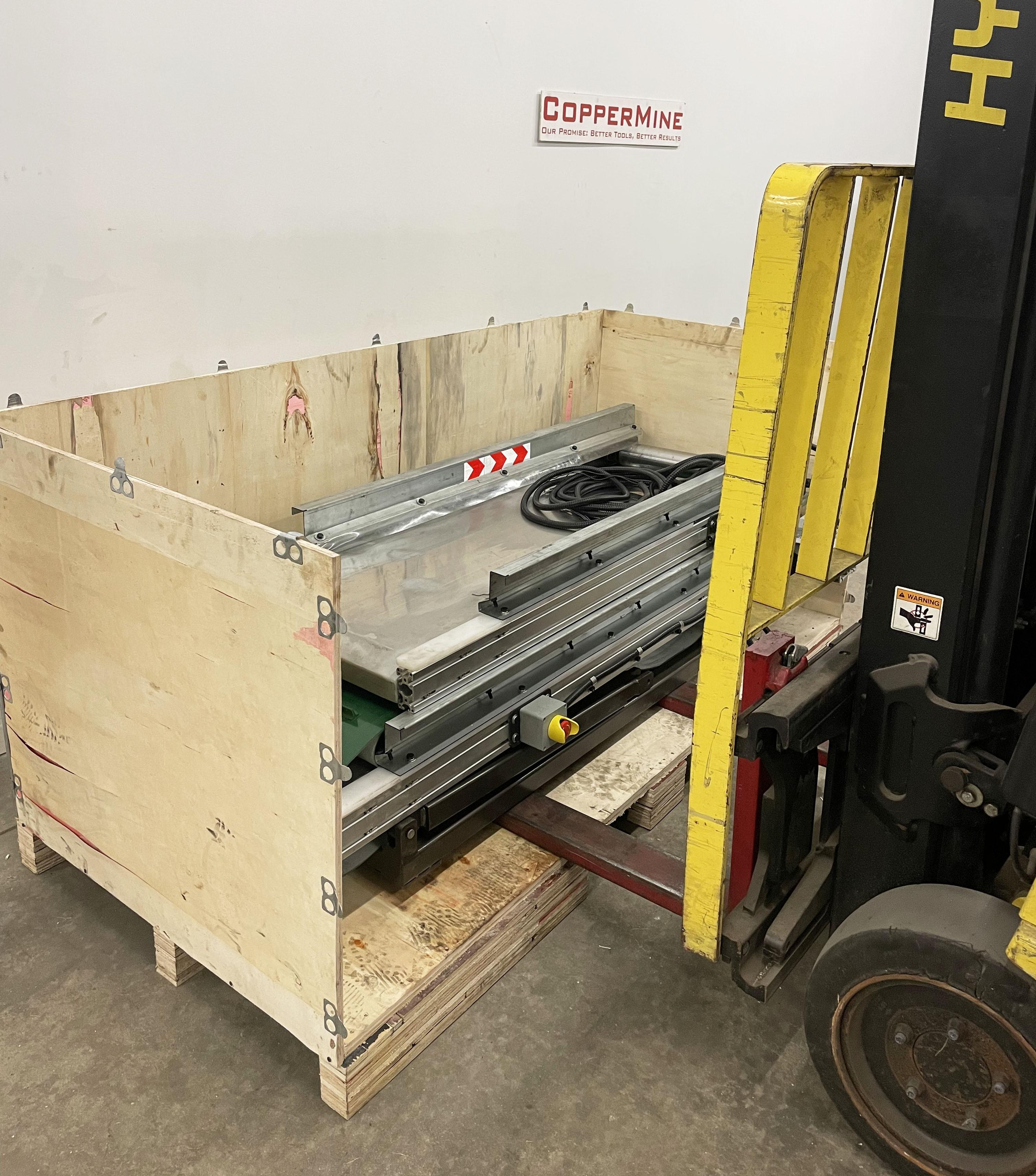
Tilt your forklift forks at a downward angle and insert them between the crate and the conveyor frame. Slide your forks all the way through to the back the back of the crate. Tilt your forks back, lift, and remove the remainder of the conveyor from the crate.
Assembling the main conveyor frame.
5. Install the Wheels
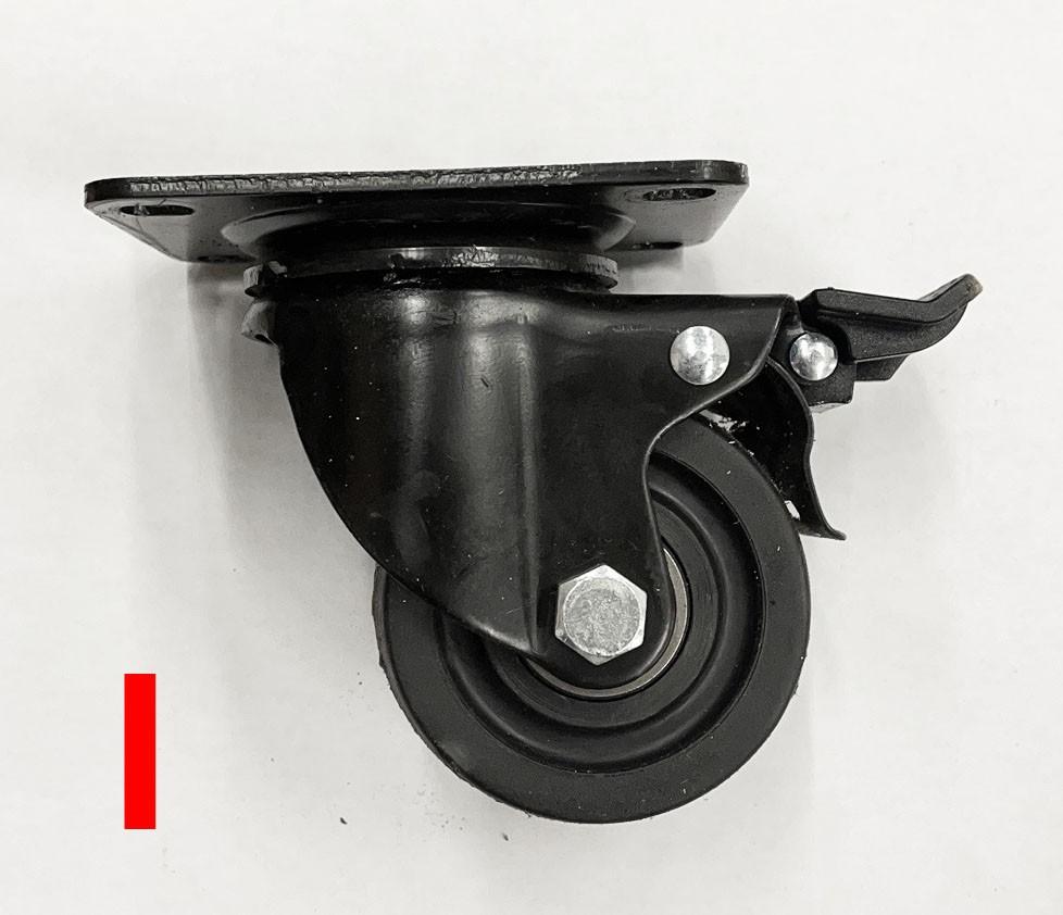
Remove the 4 Caster Wheels (I) from your parts box and install them to the bottom of the conveyor frame while it is lifted on the forks. Lower the machine onto the ground.
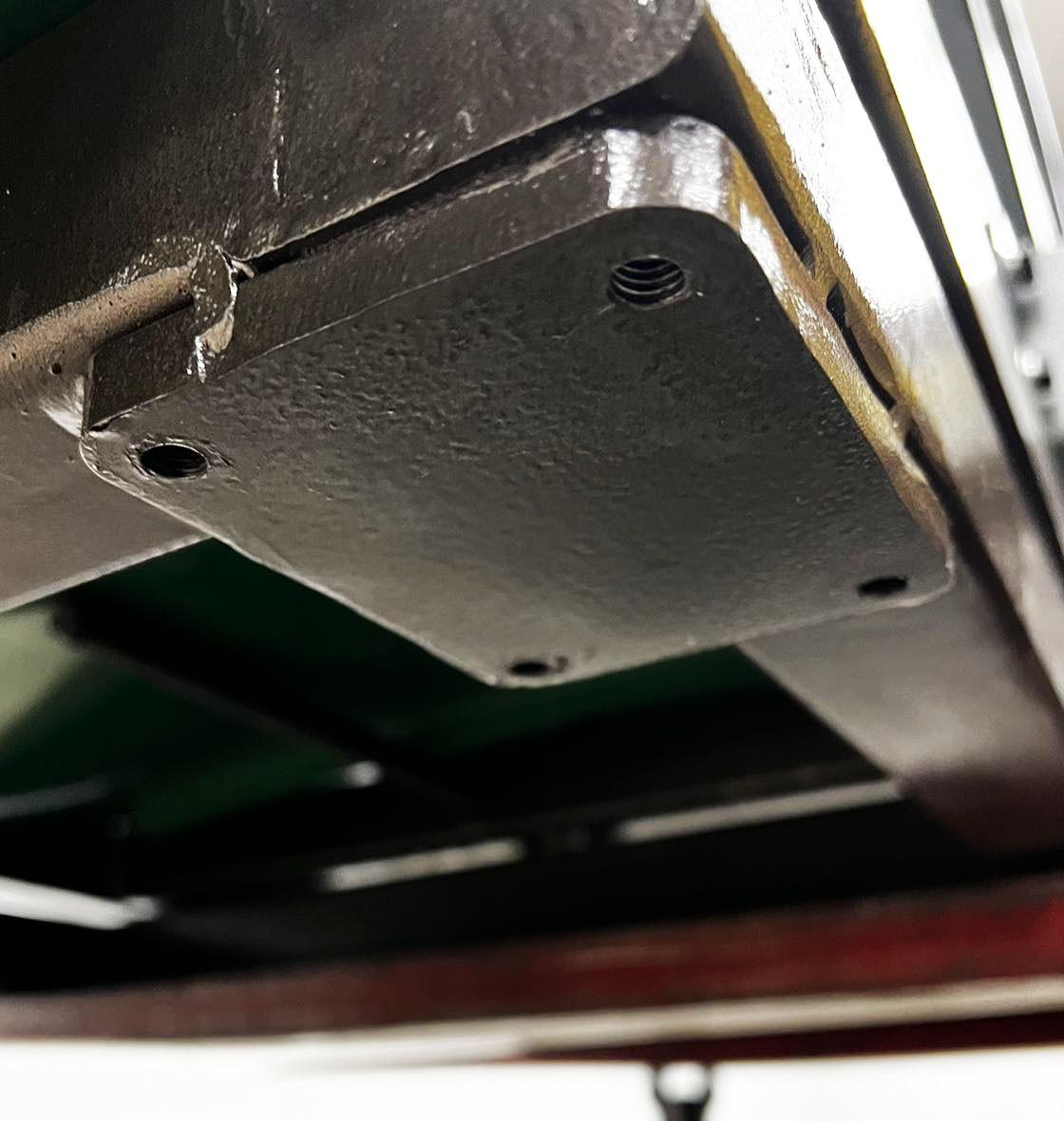
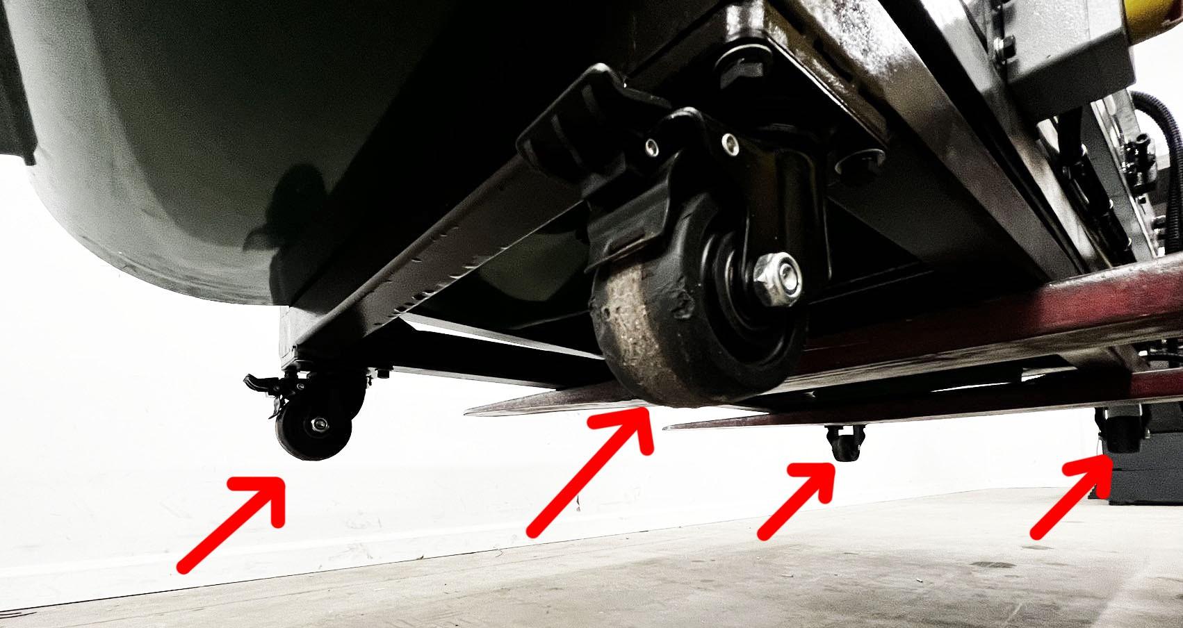
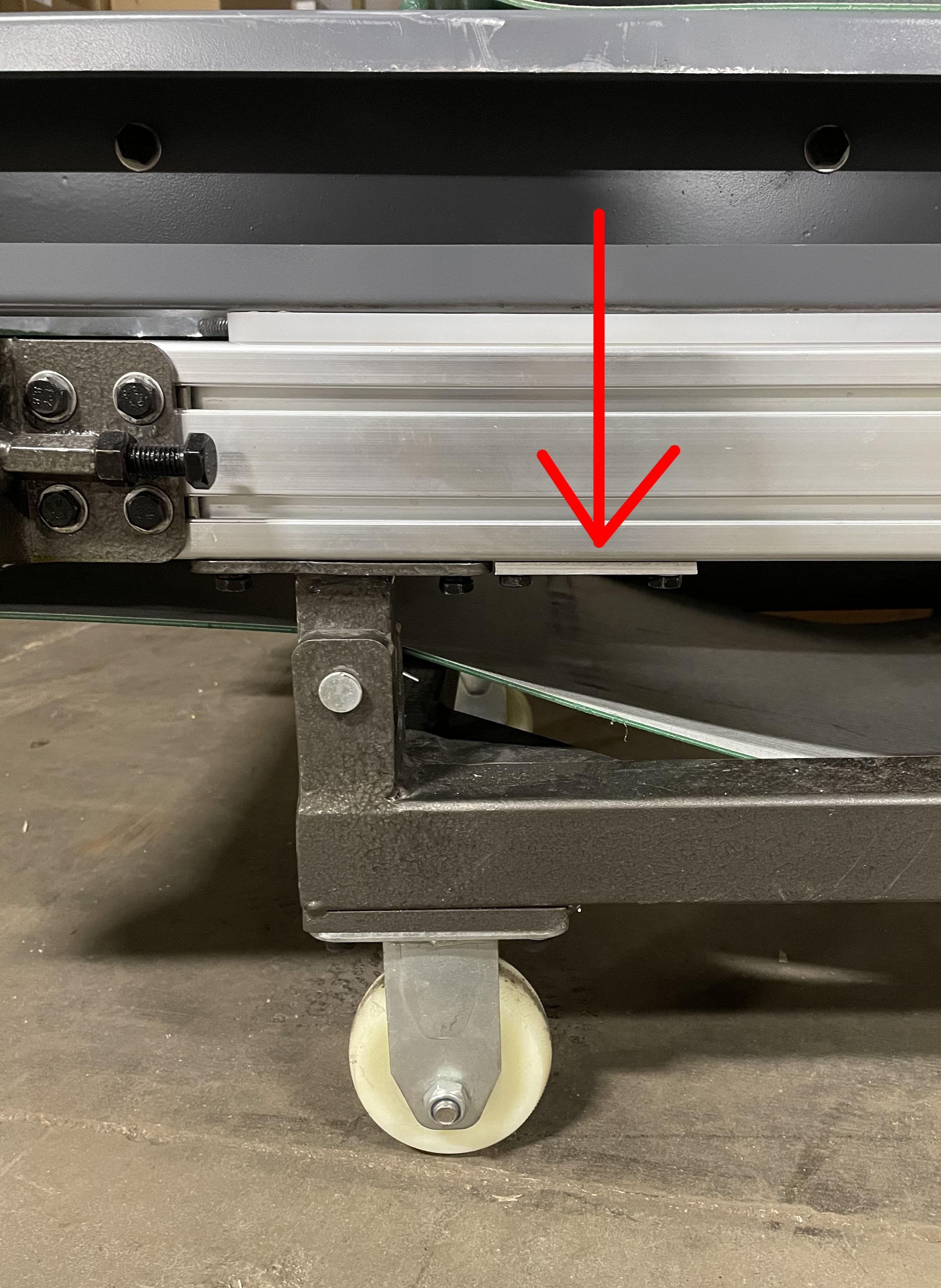
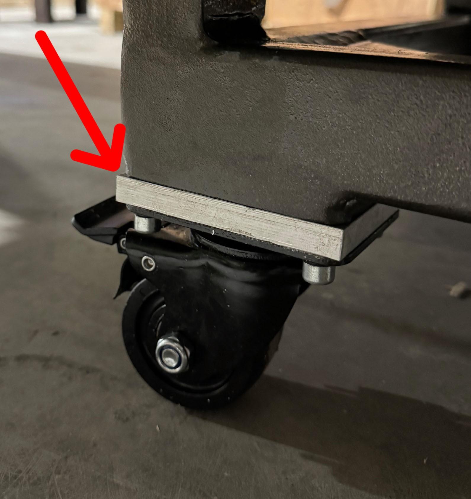
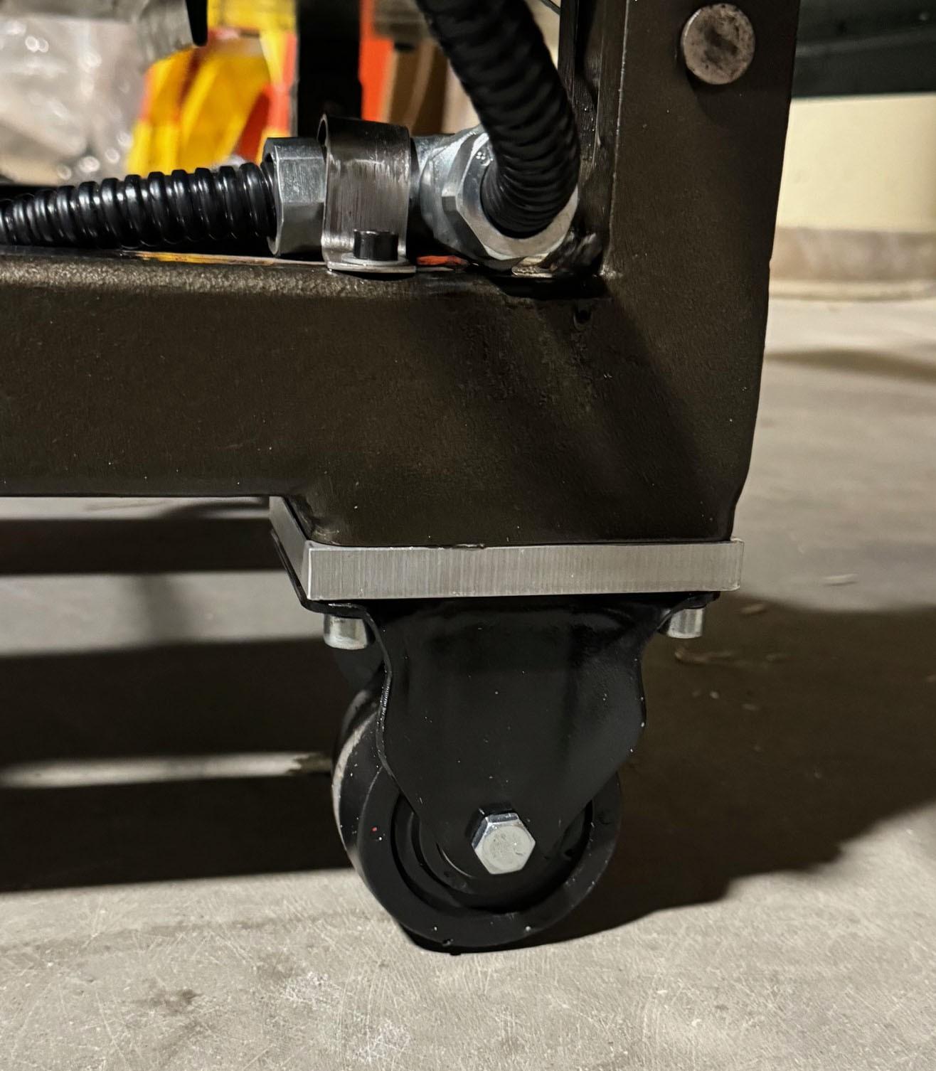
NOTE: In some cases the weight of the cross-belt magnet can cause the conveyor to lean more to one side. If you discover this with your conveyor please contact customer support and we will diagnose the issue. A leveling spacer may be needed to offset this. If your machine comes with one please see the installation picture below for assembly.
6. Separate the Conveyor
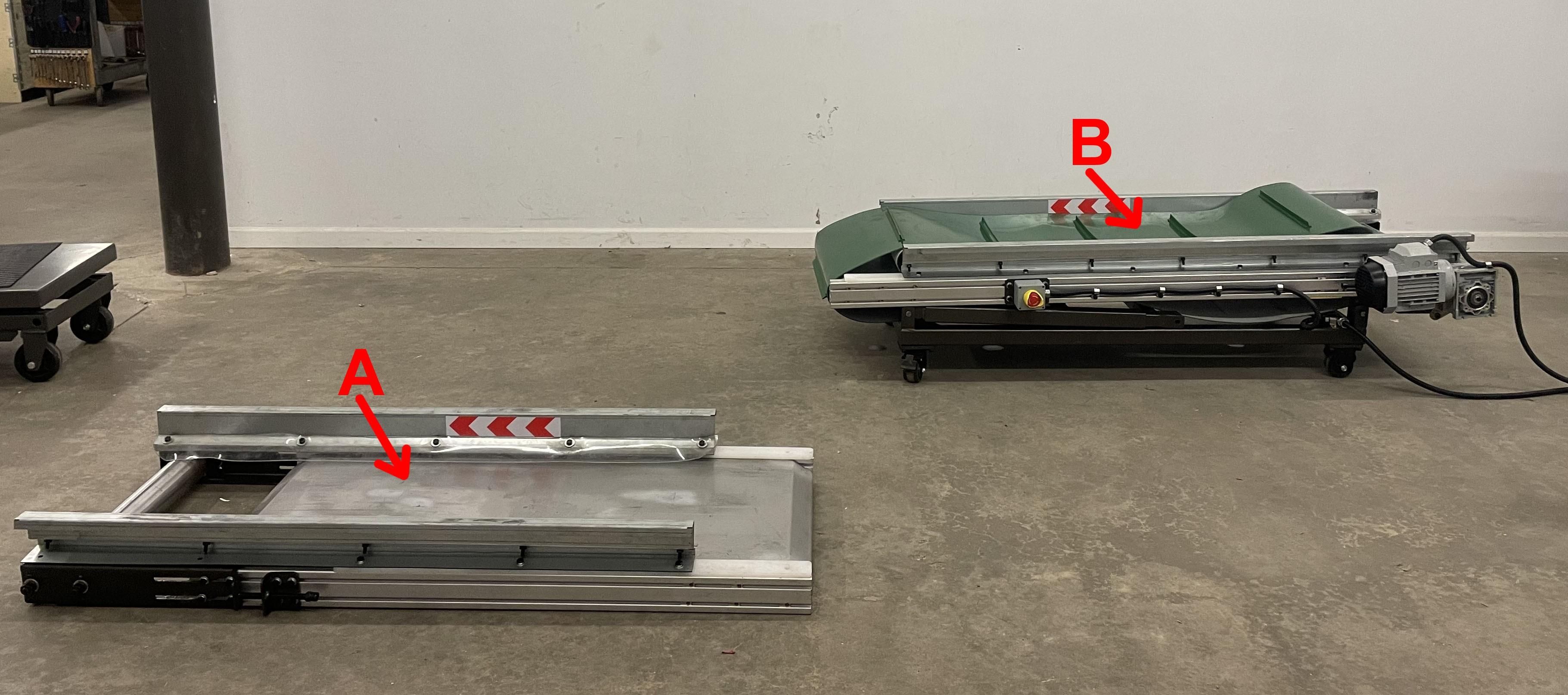
Remove the top section of the conveyor (PART A) from the bottom section (PART B) and extend the belt fully.
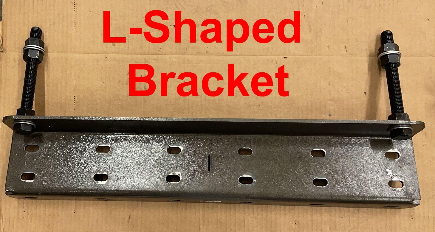
Locate the prearranged bolt sockets on the side and bottom of the conveyor frame. Align your L-Shaped bracket with these holes and use the screws from your parts box to install.
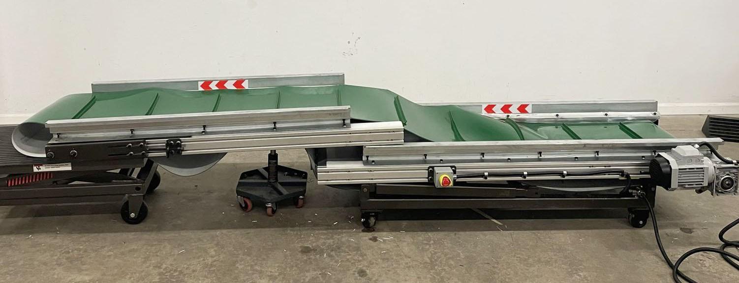
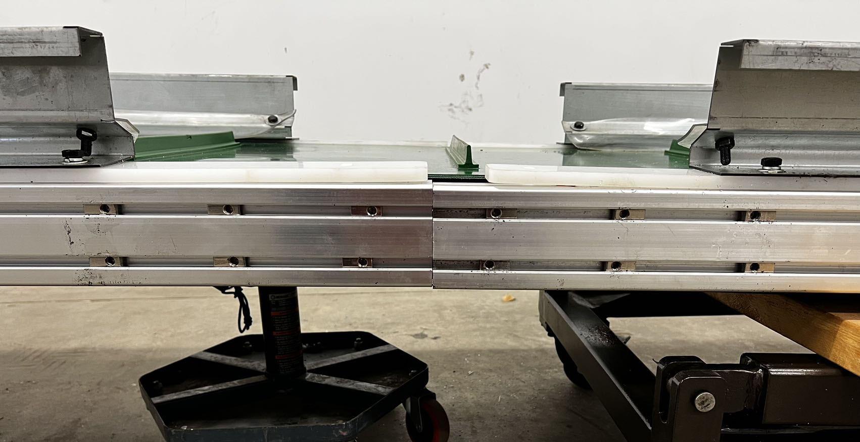
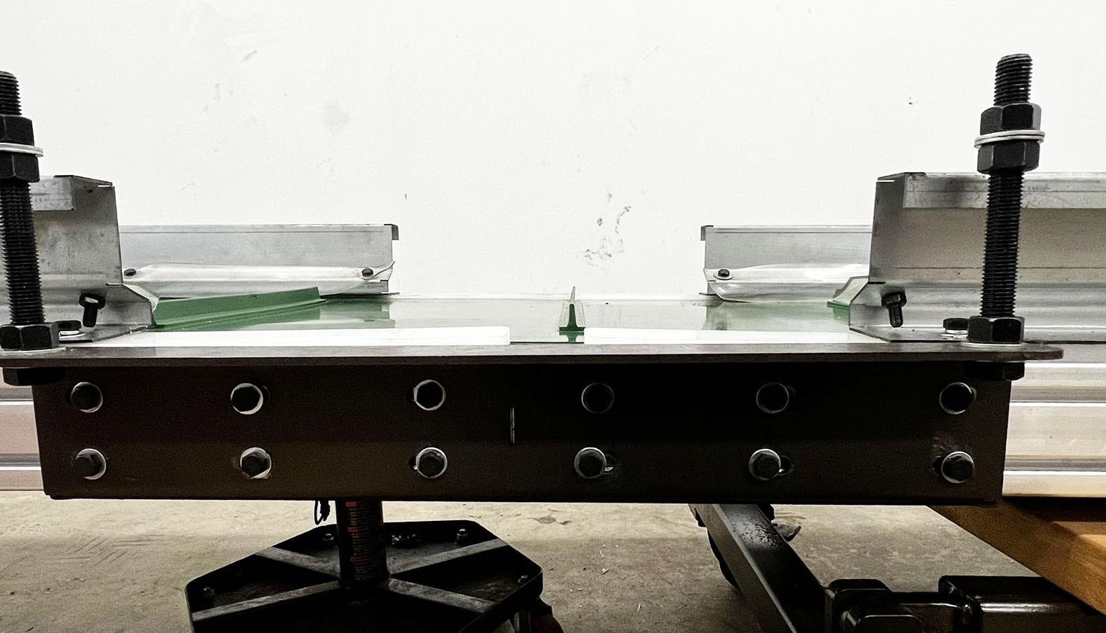
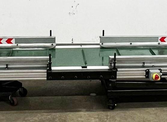
Insert (Part B) of the conveyor frame into the conveyor belt (Part A). Connect (Part A) to (Part B) using the provided L-brackets. The bolts and nuts used for the connection have been pre-mounted on the bracket. Slide the mounted nuts into the slots of (Part A) and (Part B). Make sure the joint of the two frame segments is located at the center of the connection bracket then tighten the bolts.
9. Install the Discharge Hopper
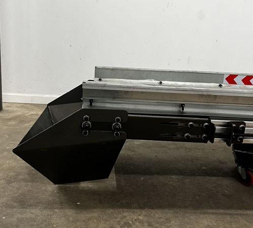
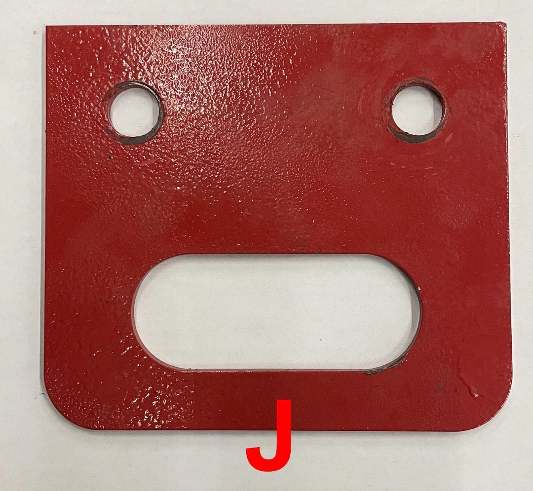
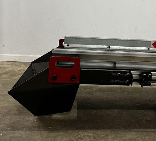
Install the discharging hopper (C) onto (Part B) of the conveyor frame using the eight (8) bolts provided. Also install the lifting handles (J).
10. Install the Feeding Hopper
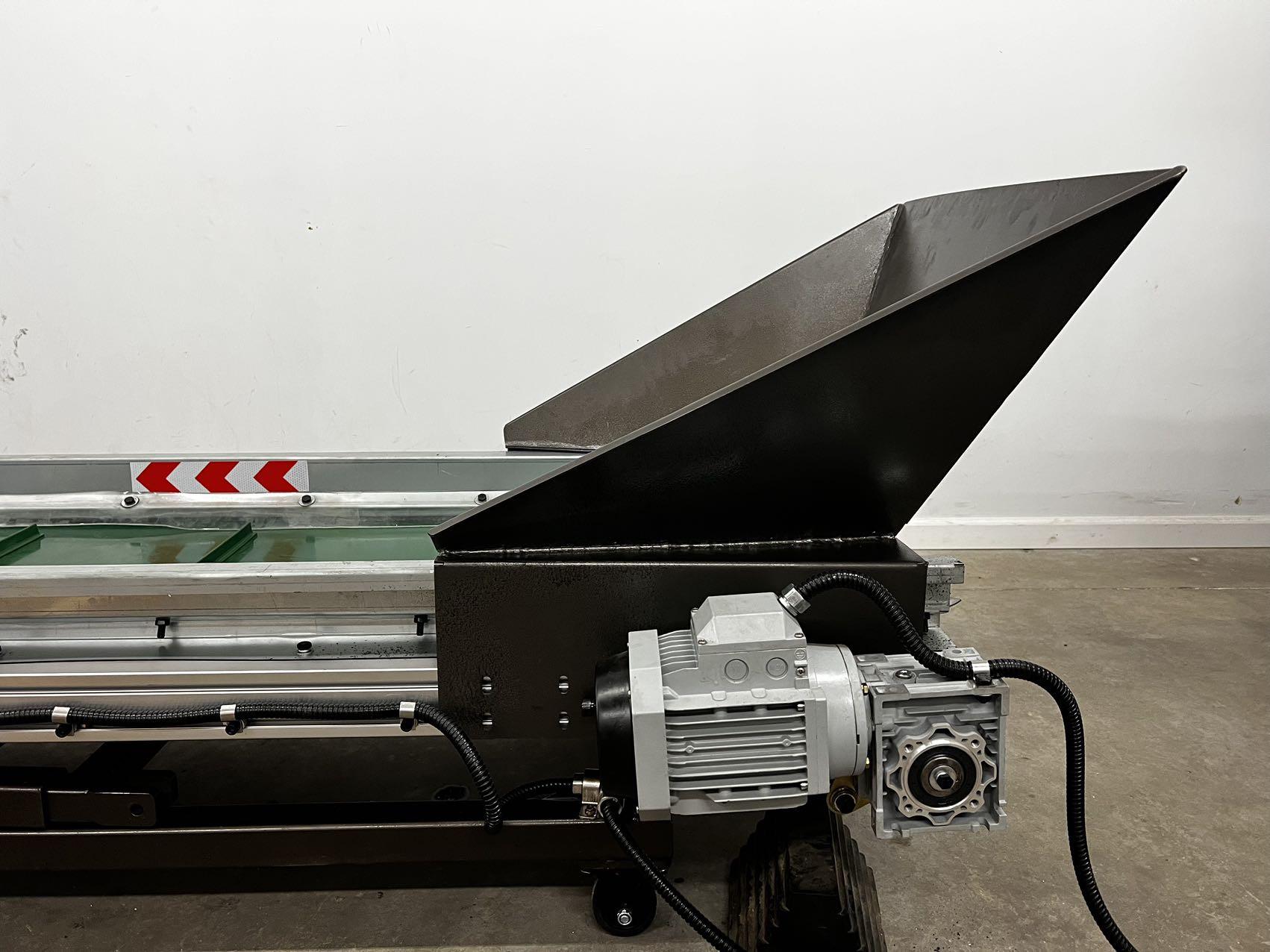
Install the feeding hopper (E) onto (Part A) of the conveyor frame using the four bolts provided.
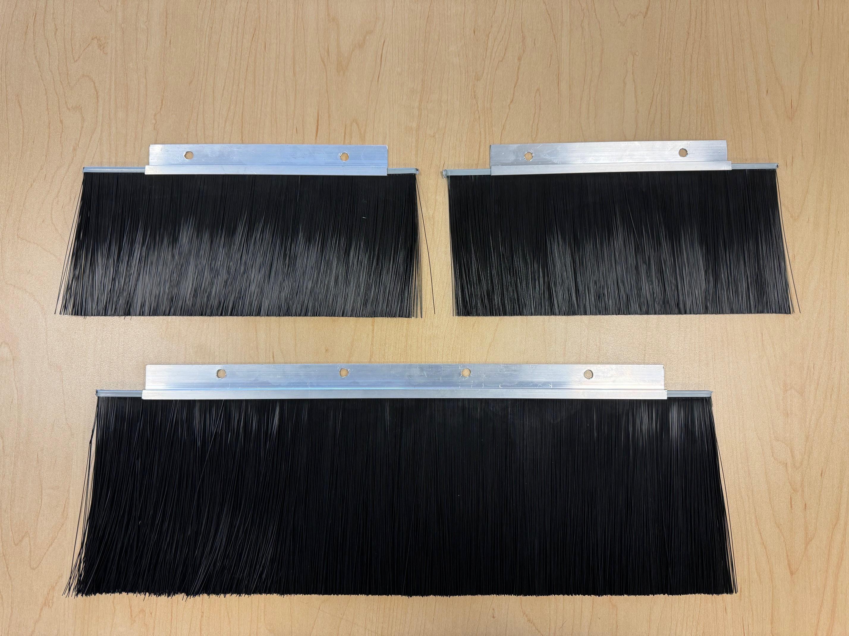
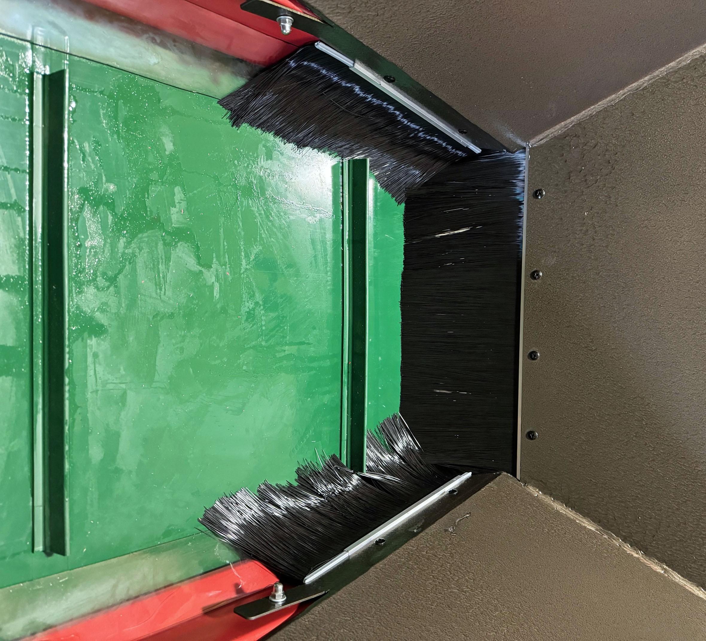
NEW: Material collection brushes.
The machine will come with 3 brushes. The installation brackets are already installed on the feeding hopper. Simply slide the brushes into the brackets before installing the feeding hopper to the conveyor. These are designed to prevent material from escaping the conveyor and falling onto the floor. On occasion some material may slip through.
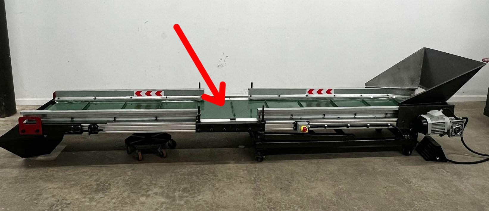
Install the cross-belt magnet (B) onto the four bolts pre-installed on the L brackets. The motor should be on the same side as the conveyor motor. (Pay attention to the direction of the Cross-belt Magnet).
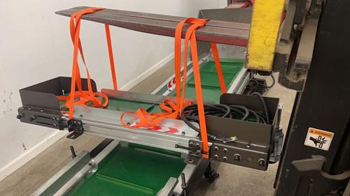
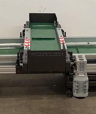
Using the provided lift handles and your forklift hoist the machine to the appropriate height and secure the adjustable incline support frame.
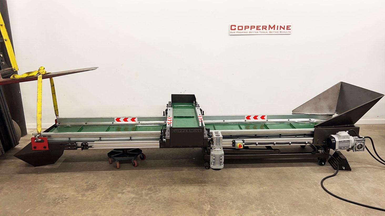
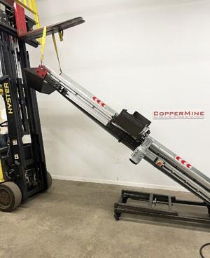
13. Attaching the Leg Pin Holder
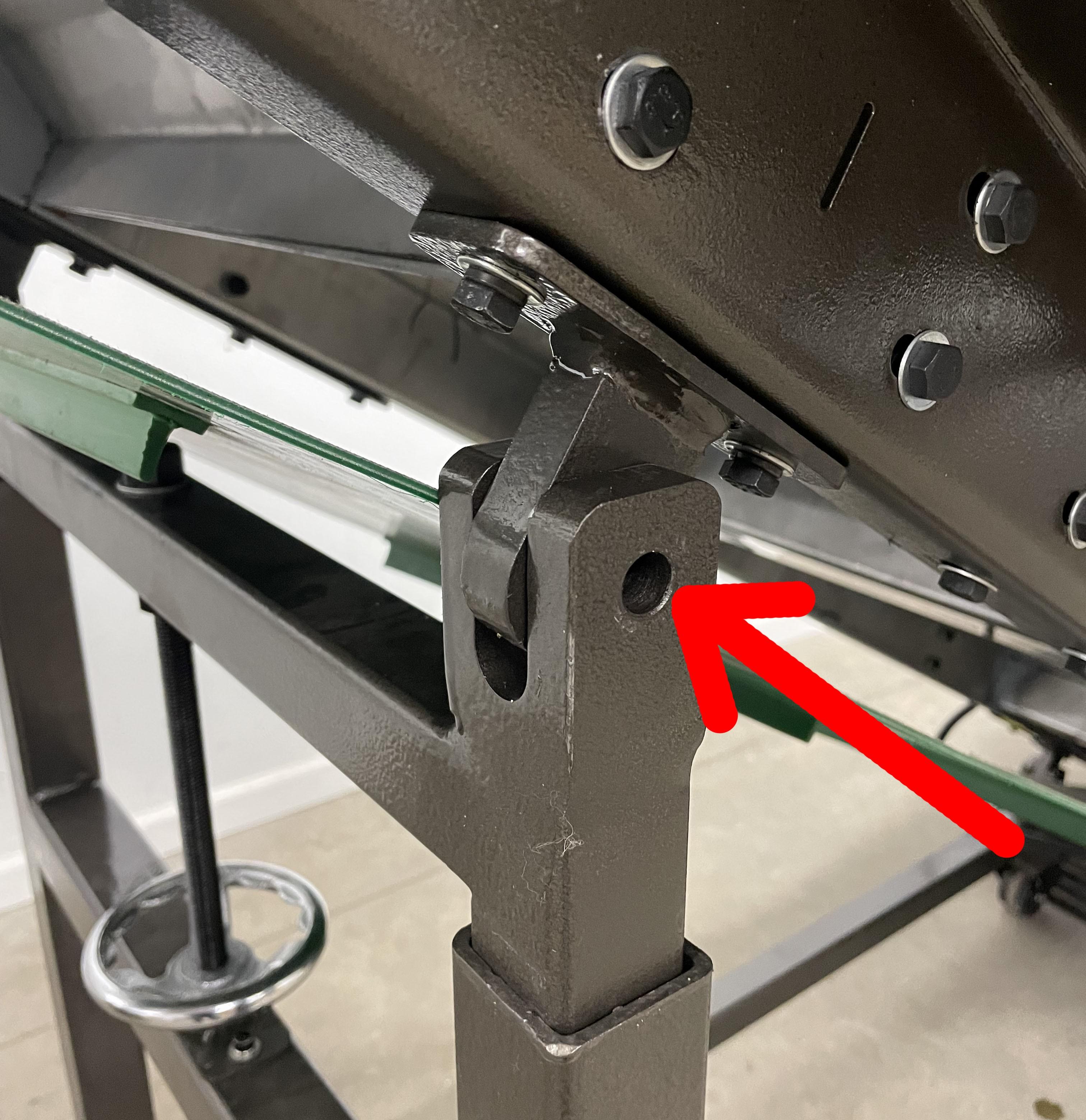
Attach the Leg Pin Holder to the L-Shaped Bracket. There is a designated marked area to install.
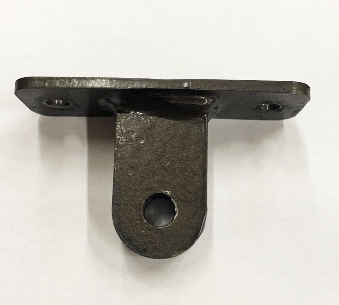
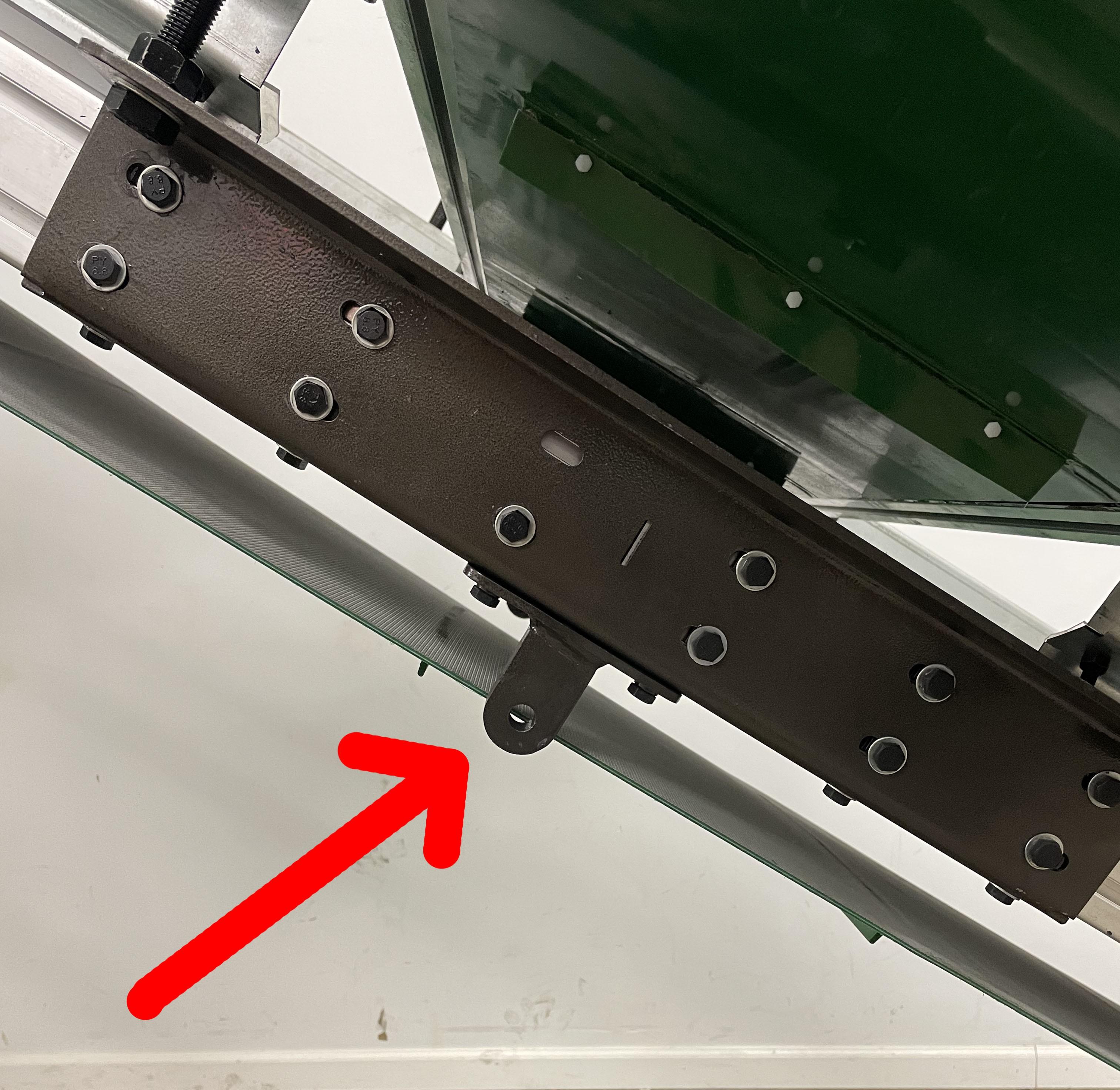
14. Attaching the Adjustable Conveyor Leg
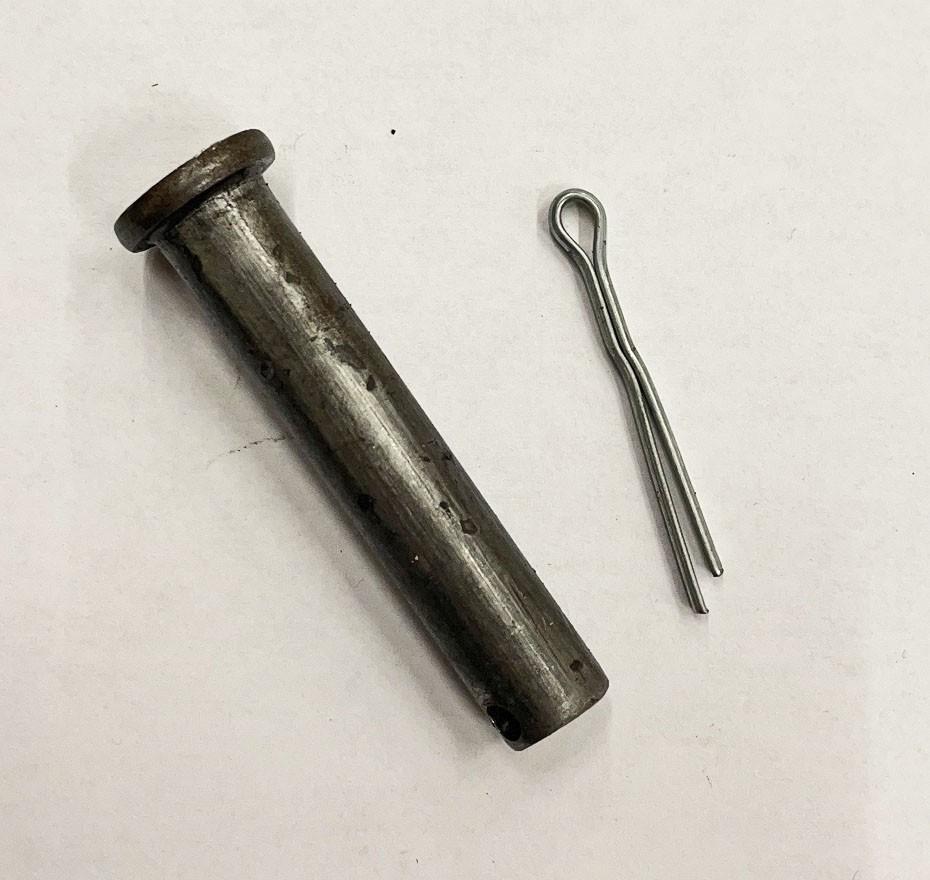
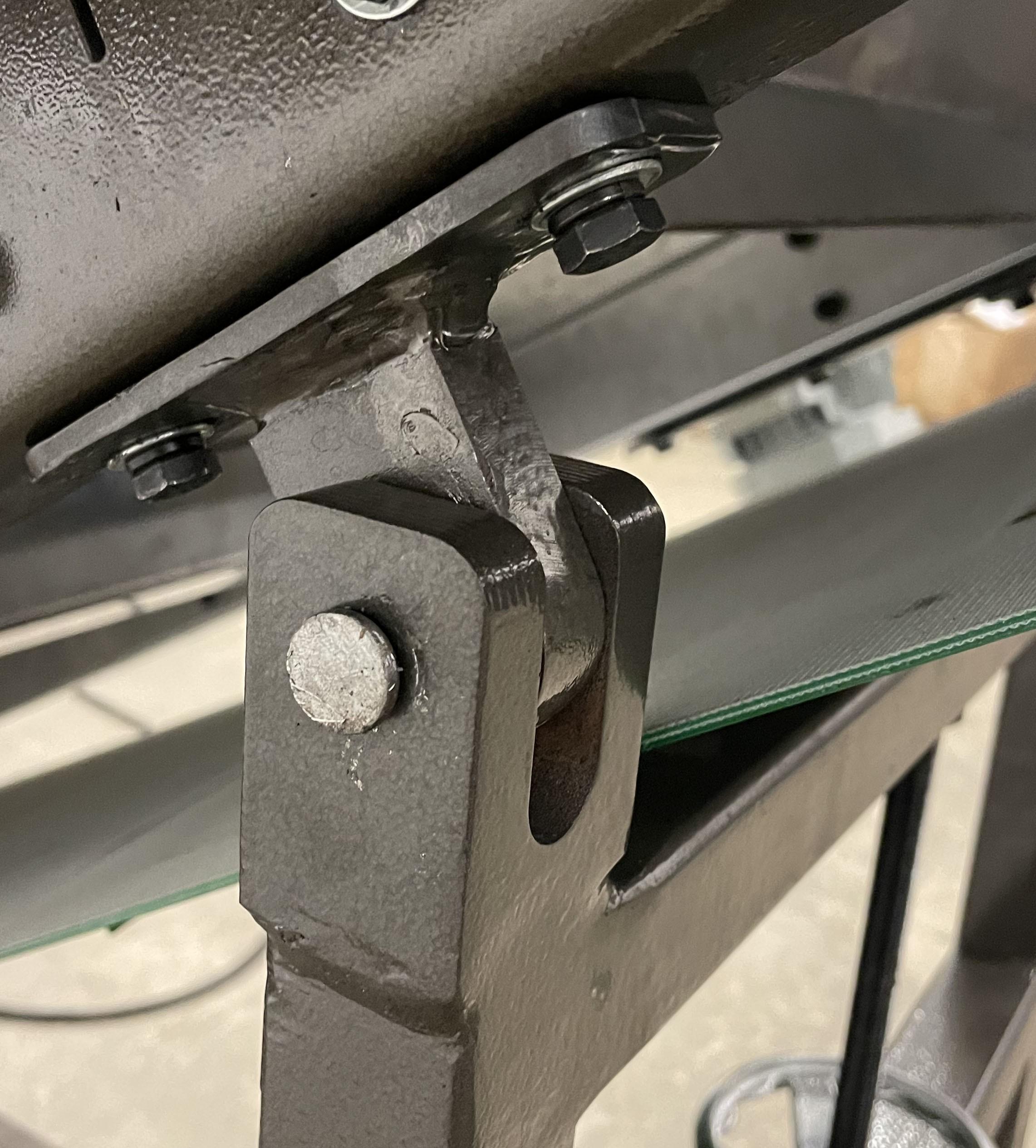
Using the Pins provided lift the adjustable leg into place and slide the Pin through each leg and leg pin holder as shown. Once they are installed use the clip to lock the pin into place.
15. Add Accessories
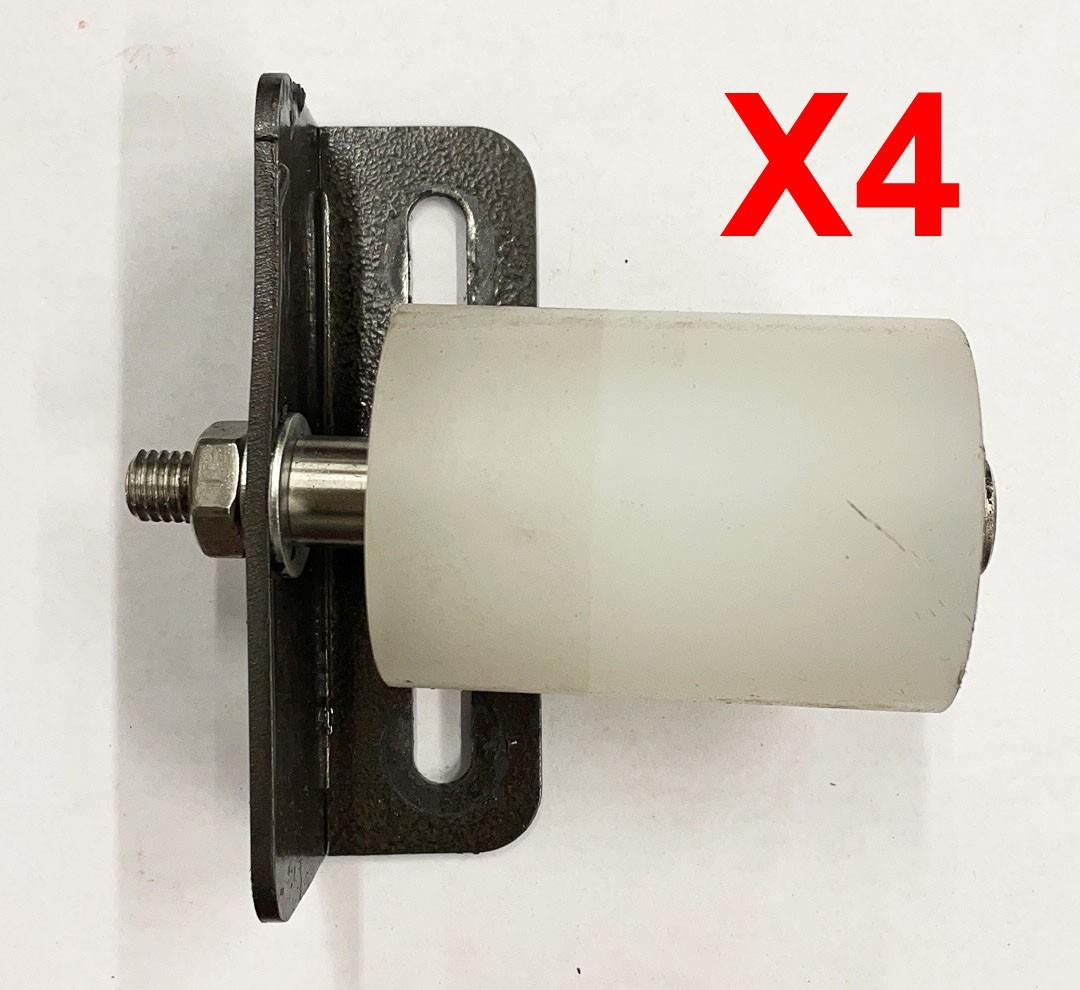
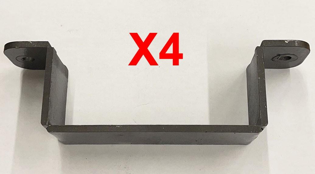
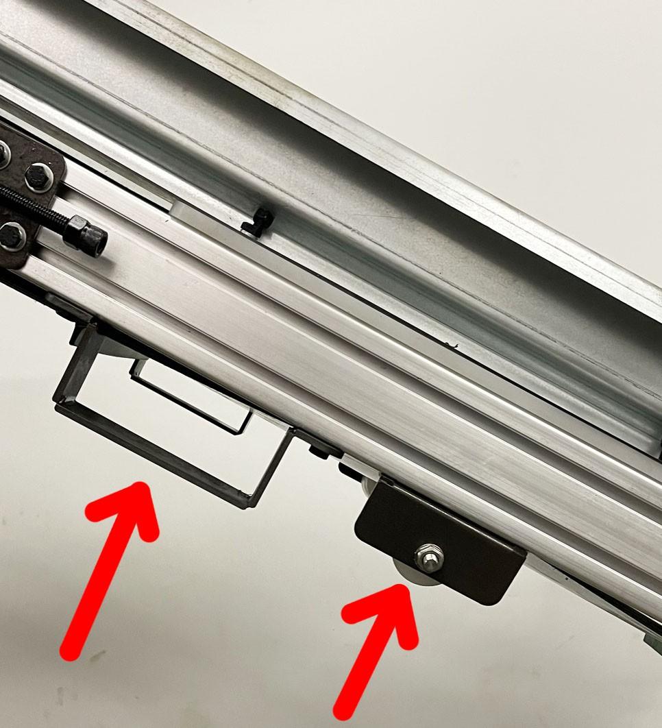
Add the FOUR (4) conveyor roller wheels and the FOUR (4) fork lifting handles to the bottom of the conveyor. (The areas are marked and labeled).
16. Adjusting the Inclination of the Conveyor
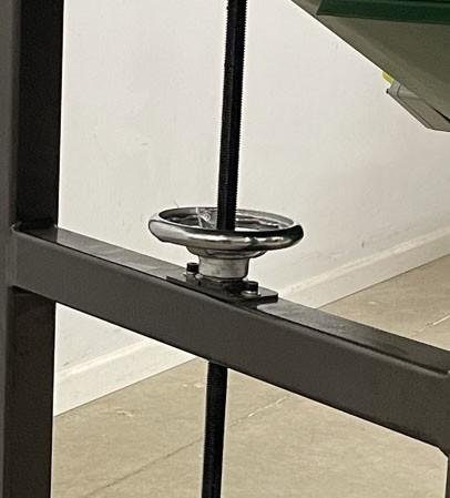
Adjust the angle of the main conveyor belt using the Hand Wheel (D) until the Discharge Hopper (C) reaches a desired height.
The safety belt covers protect operators during operation from the exposed moving belt while monitoring the output of the machine. It is important that they are installed before you operate the machine. These covers are marked with corresponding letters to match their location and make assembly easier. Use the nuts included in your parts bag to install them.
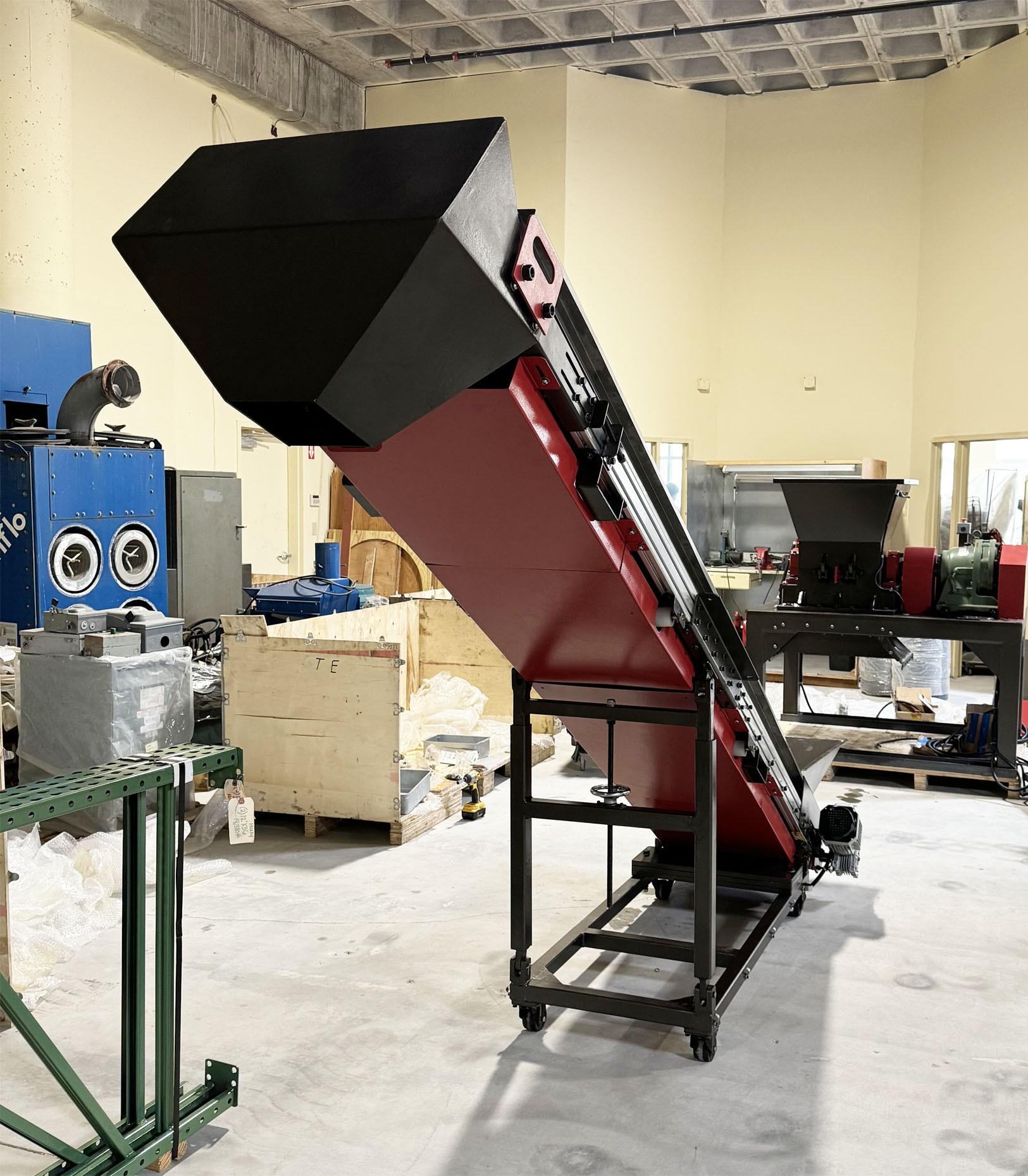
Once you have found your desired height and location for the conveyor lock the caster wheels into place. When you need to move the conveyor unlock the caster wheels and freely move the conveyor.
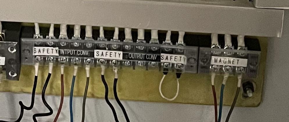
• Install the two E Stop Buttons in their designated spaces on each side of the conveyor frame. Connect the wires to the “safety” in the electrical cabinet.
• A licensed electrician must be used to wire the conveyor.
• Wire the conveyor motor and the cross-belt magnet motor to the electrical cabinet as shown below.
Wire 3-Phase 208VAC main power to the electrical cabinet using 4 AWG wires or thicker. The main power ground should be connected to the grounding post in the electrical cabinet. The machine chassis must also be grounded separately using an 6 AWG wire or thicker.
• Before powering on the machine, check to make sure all moving parts (blades, conveyor, motor, etc.) are clear from debris.
• Flip all of the breakers in the electrical cabinet on.
• Power on the main breaker from the electrical panel making sure the line voltage meter is reading within (208 – 220VAC) range. Close and lock the cabinet. Failure will result in the electrical cabinet not receiving power.
• Power on the conveyor from the control panel making sure the current meter reads within range. (The current should not exceed 3A during operation.)
• Make sure the rotation of the belts of the conveyor are in the right direction. If the rotation direction is wrong, locate the power connection for the corresponding motor in the electrical cabinet and swap any two-phase wires out of the three.
• Set the conveyor belt tension immediately using the following instruction.
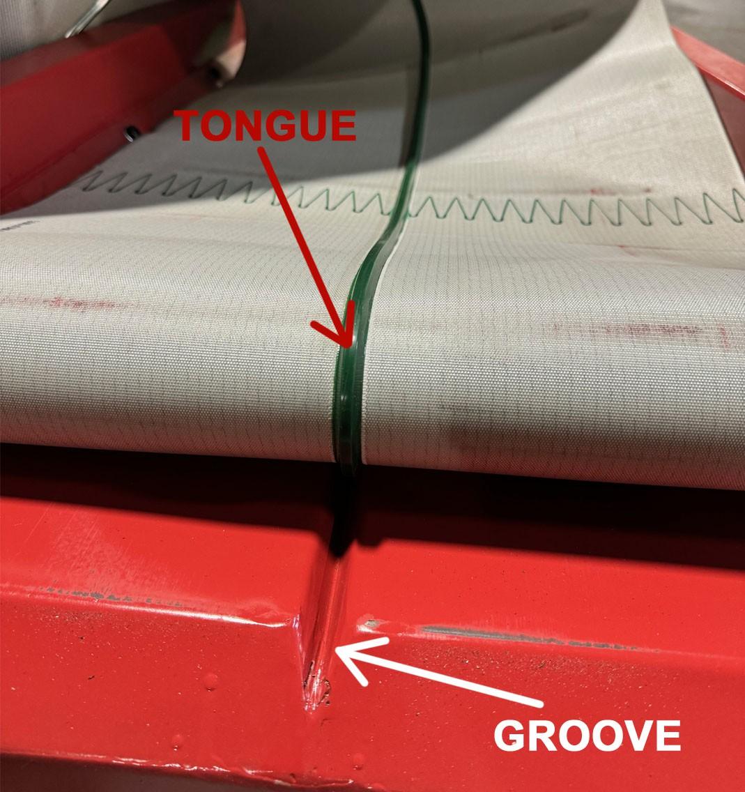
The self tracking conveyor belt uses a tongue and groove tracking system. This design makes aligning the conveyor belt easier for the customer. It is IMPORTANT that the tongue on underneath the belt is sitting properly inside of the grooves on the conveyor frame and rollers. If not set properly this can cause the belt to wear quicker and not track properly. See images on the next page.
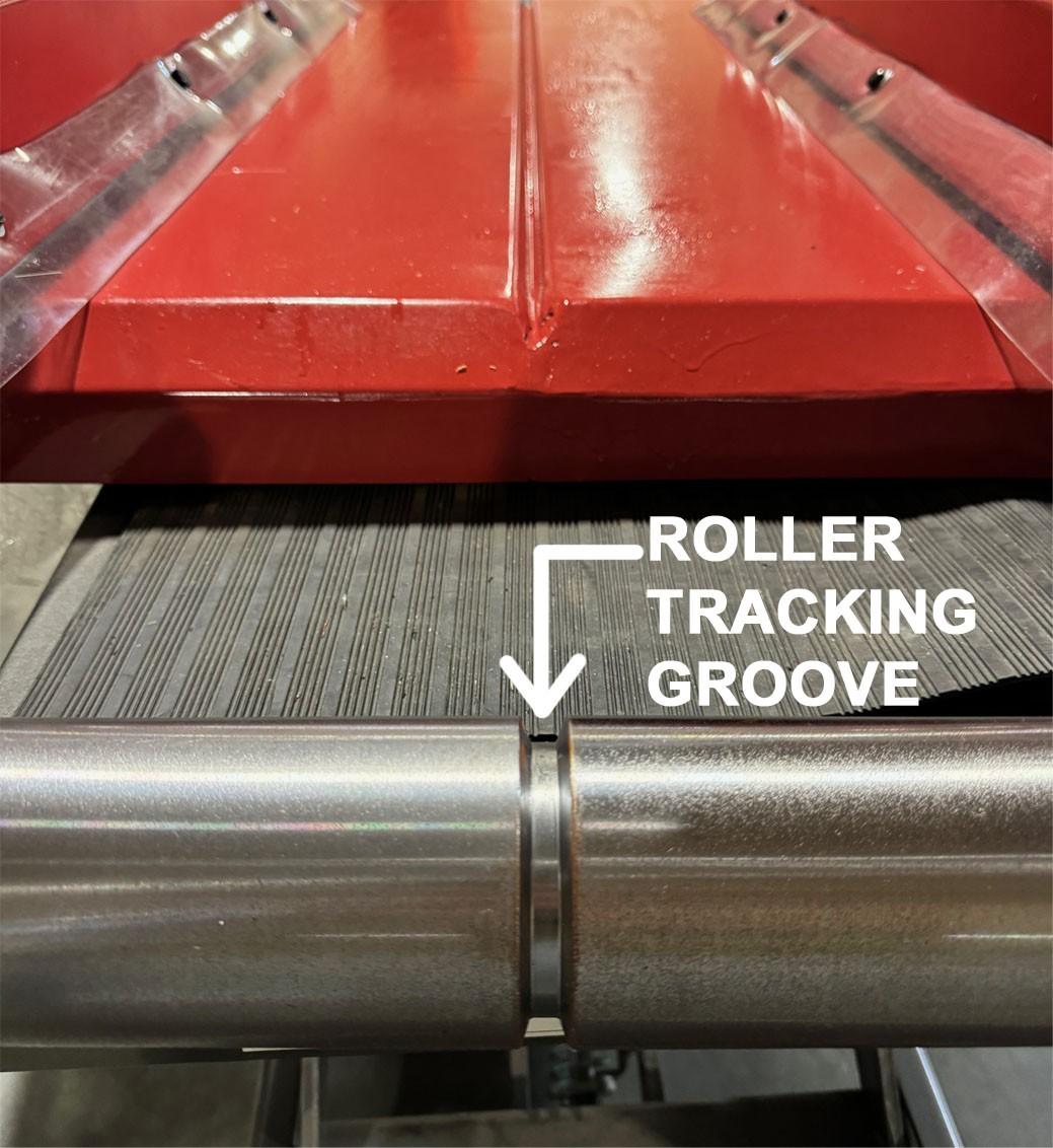
If the tension bolts are not evenly tightened, the belt is therefore unbalanced and can cause poor tracking. The adjustment of the tension bolts should always be conducted in small steps to avoid damage to the belts from over-adjustment.
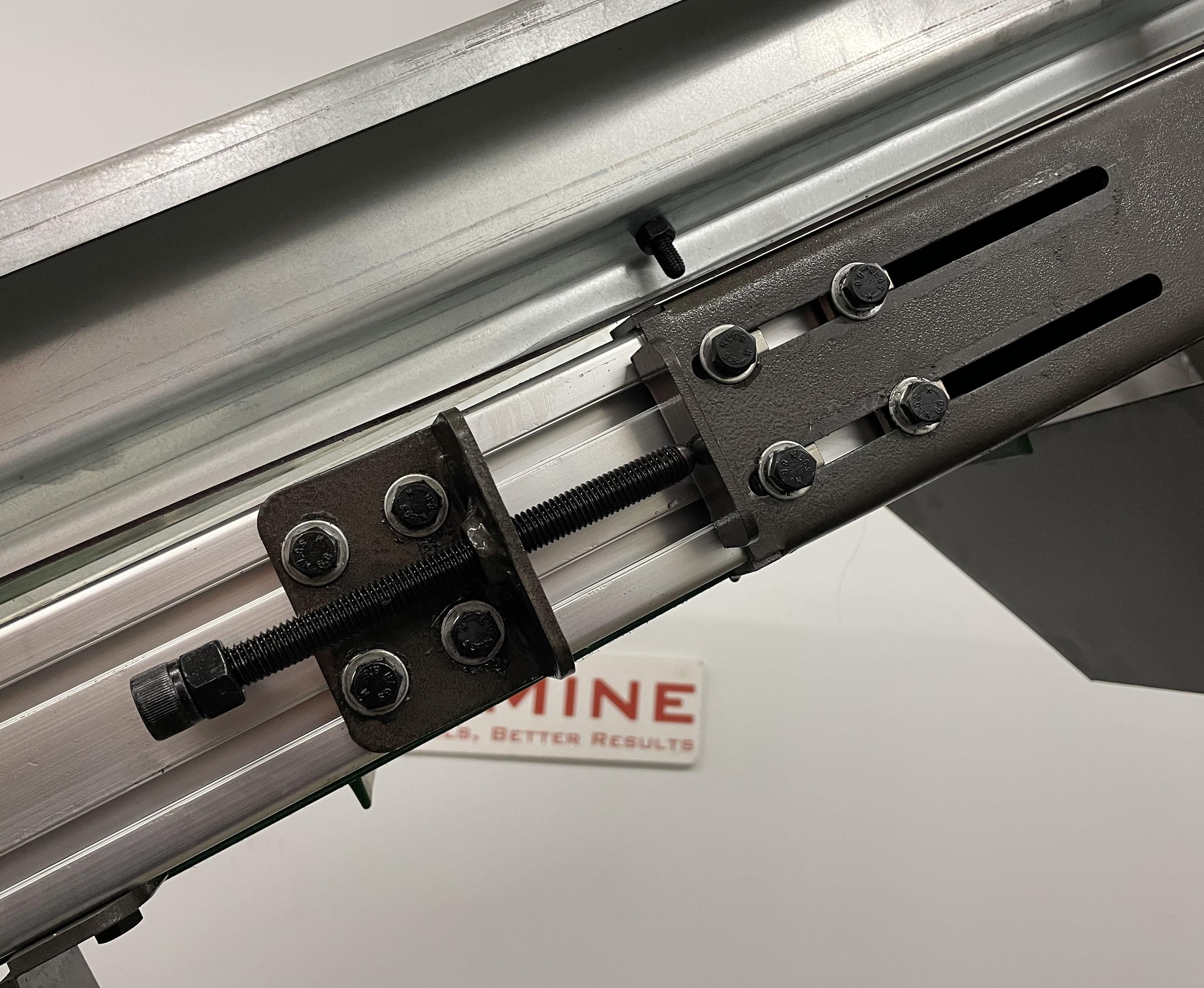
Power on the conveyor and verify the digital current meter reading is within range when both the main conveyor and magnet conveyor are running. (The current should not exceed 5A during operation.
Feeding
Feed the conveyor with materials of proper size and weight. Do not overload the conveyor.
Stop and examine the system immediately if any visual or audible signs of malfunction is found.
Turn off the main breaker in the electrical cabinet at the end of workday.
Emergency Stop
In case of an emergency, press ANY emergency button throughout the system to shut the machine down.
Maintenance
Safety Precautions
Any service or maintenance should only be performed by qualified personnel.
All power to the equipment should be disconnected and measures must be taken to prevent accidental re-connection to the power during maintenance.
Lubrication
Drive chain lubrication. The drive chains for the conveyor and the magnet should be lubricated using lubricant with grade SAE 30, such as Mobil 1™ 5W-30 motor oil. Lubricant may be applied with a brush to the slack portion of the chain periodically, preferably once every eight hours of operation. Lubrication volume and frequency should be just enough to allow oil to seep into the chain structure and keep the whole chain wet.
Bearing lubrication. All bearings should be lubricated with roller bearing grease of medium consistency, such as Mobilux EP2. Grease could be applied through the installed grease fittings using a manual grease gun.
Motor speed reducers have been pre-filled with long-lasting lubricant. No extra lubrication is required for these reducers under normal conditions. Contact CopperMine for further information if any leak is found or the motor is malfunctioning.
Conveyor Belts
It is normal for conveyor belts to stretch during use, which may cause them to track poorly (shifting to one side as they ride, instead of staying in the center along of the conveyor). Check the belt visually on a regular basis, stop the conveyor immediately if the belt does not track properly. Proper belt slack. The return belt must have appropriate slack under proper belt tension. Do not run an over or undertightened belt. If the belt is too loose to function properly, adjust the tension bolts on both sides of the end pulley evenly to tighten the belt, and vice versa. It is normal for chains to gradually stretch due to normal wear. As this causes extra slack, adjustment of slack is required. All drive chains should be visually inspected, on a regular basis, to monitor the slack change. Adjust the location of the motor or replace the chain to remove excessive slack and prevent possible damage from a jumping chain. However, over-tensioning the drive chains should be avoided. Push up and down the chain in the middle of its span and notice its free movement “A”, as shown in the diagram below. For the drive chain of the conveyor, A = 1 inch; for the drive chain of the cross-belt magnet, A =0.4 inch.

Conveyor Belts
It is normal for conveyor belts to stretch during use, which may cause them to track poorly (shifting to one side as they ride, instead of staying in the center along of the conveyor). Check the belt visually on a regular basis, stop the conveyor immediately if the belt does not track properly.
Proper belt slack. The return belt must have appropriate slack under proper belt tension. Do not run an over or under-tightened belt. If the belt is too loose to function properly, adjust the tension bolts on both sides of the end pulley evenly to tighten the belt, and vice versa.
Make yourself familiar with the equipment structure, the installation, operation and maintenance procedures before installing and operating this equipment.
• A: Chopper Opening; B: Chopper Bearing; C: Chopper Lock; D: Chopper Opening Handles; E: Vacuum Duct; F: Vibration Table; G: Blower Duct; H: Take Two Copper Outlet; I: Main Chopper Motor; J: Clean Copper Outlet; K: Leveling Foot; L: Vibration Spring; M: Blower Tube/ Access Door; N: Chopper Quick Access Door; O: Vibration Table Quick-Clamps; P: Vacuum Damper; Q: Vibration Motor; R: Vibration Table Screen; S: Insulation Outlet; T: Blower Motor
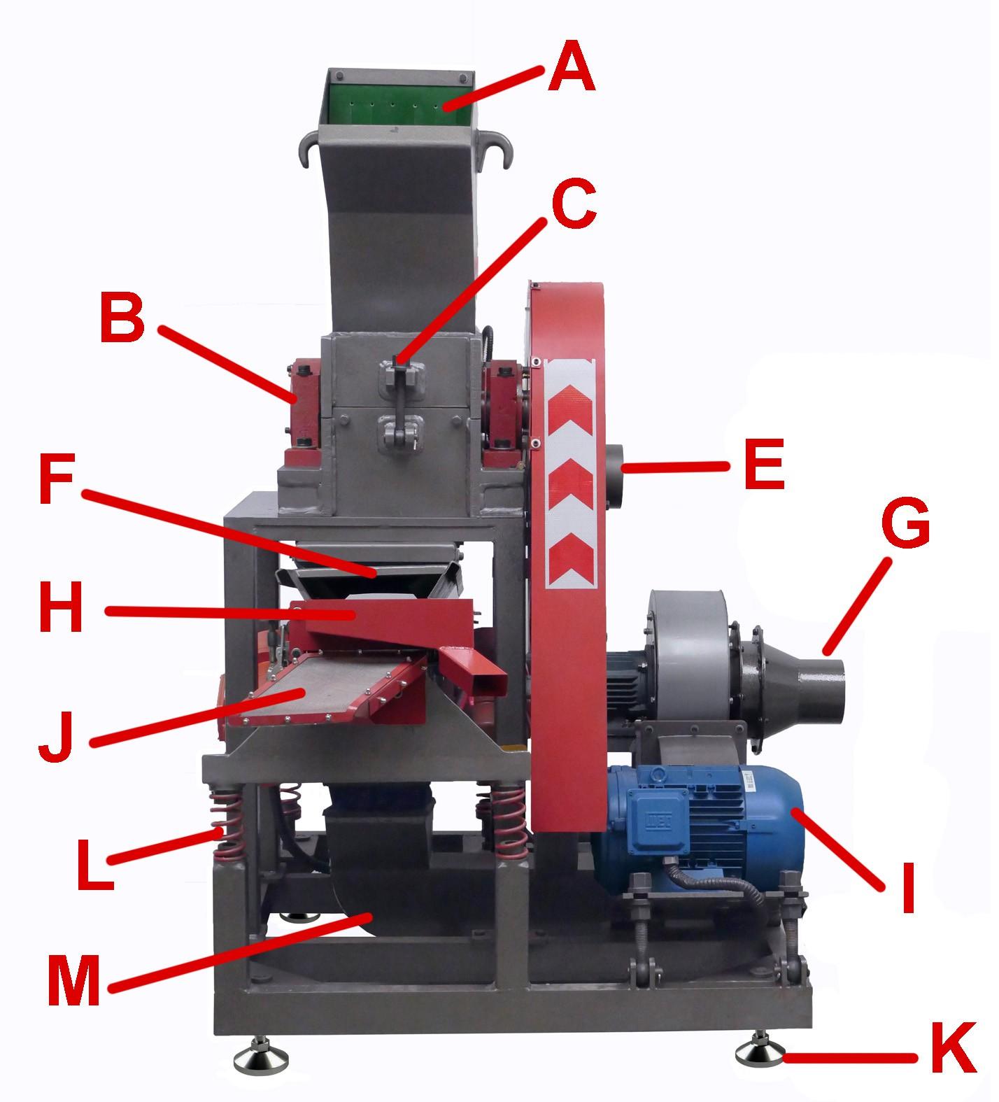
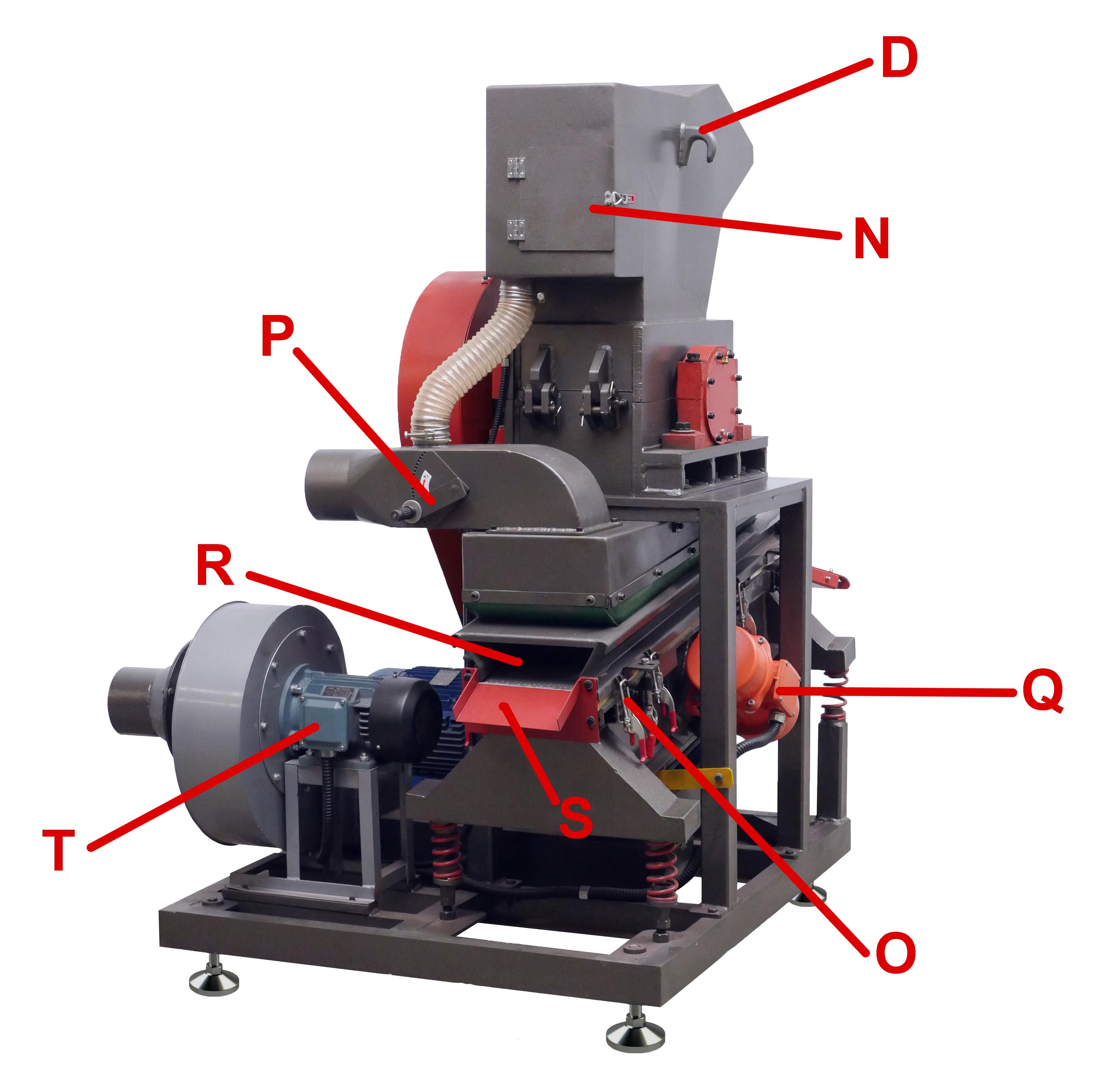
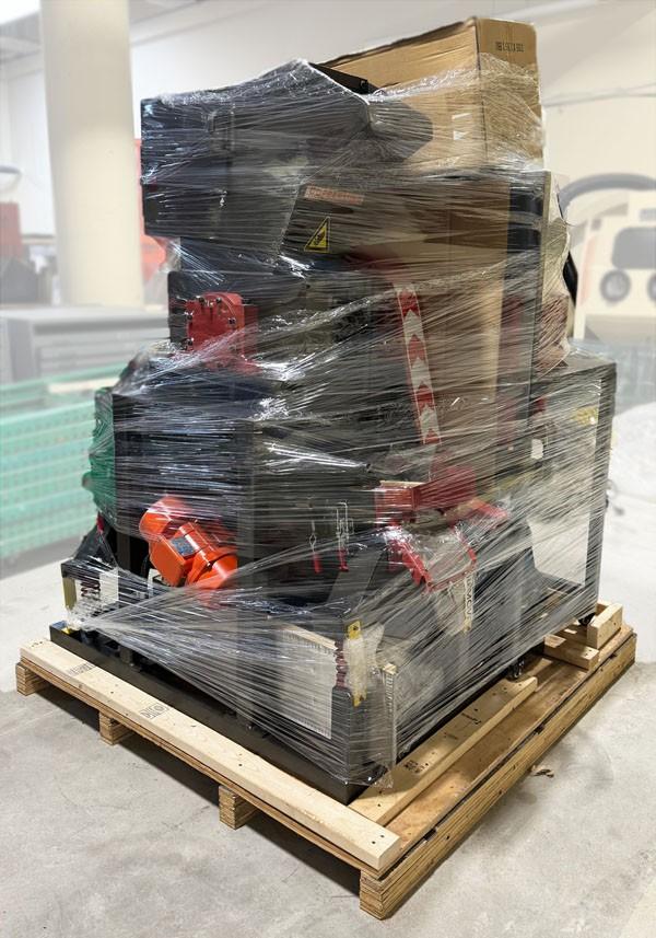
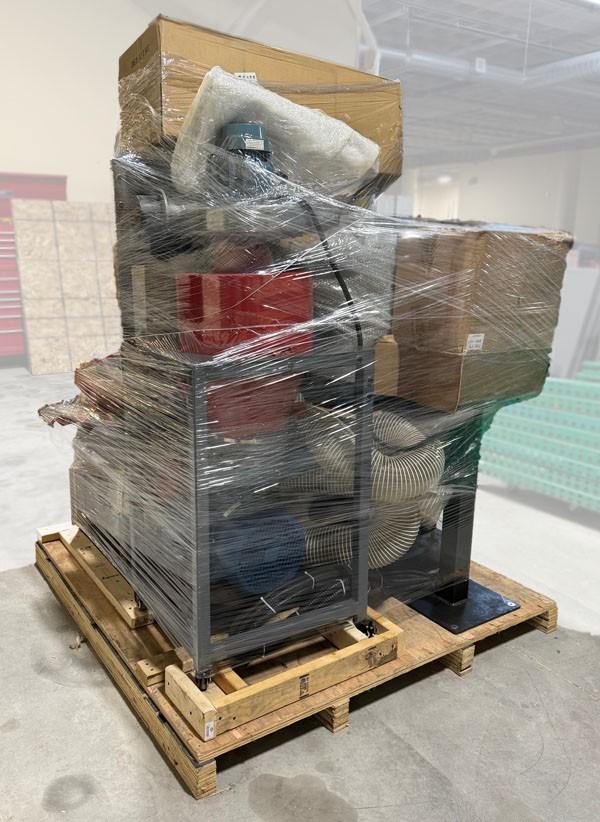
• The granulator is equipped with adjustable rigging jacks. They have built-in swivel pads that do not damage the floor.
• Use a wrench to turn a jack no more than four turns at a time, switching to the next jack to ensure a balanced rise or descent.
• The maximum rise is 3-1/2”.
• Roll in a pallet jack under the granulator. Make sure the center of gravity of the granulator is located directly above the center line between the forks.
• The granulator must be lowered to reduce its center of gravity before operation. Use the rigging jacks to level the granulator if the floor is slightly sloped.
• The granulator is designed to be used indoors.
• Choose a location that has a flat and sturdy floor, is close to electric power, and well lit.
• It is NOT necessary to bolt the granulator down the floor.
• The location should be dry and have a low level of dust.
• The location should allow noise level produced by the granulator.
• Shim the machine chassis with wood shims if copper is not evenly distributed on the vibrating table during operation (Refer to How to Operate the Granulator for details).
Check Settings
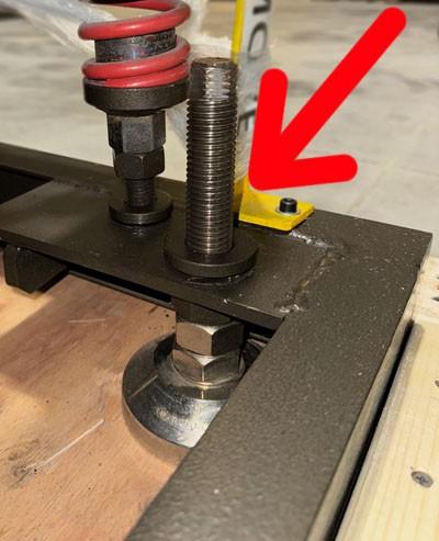
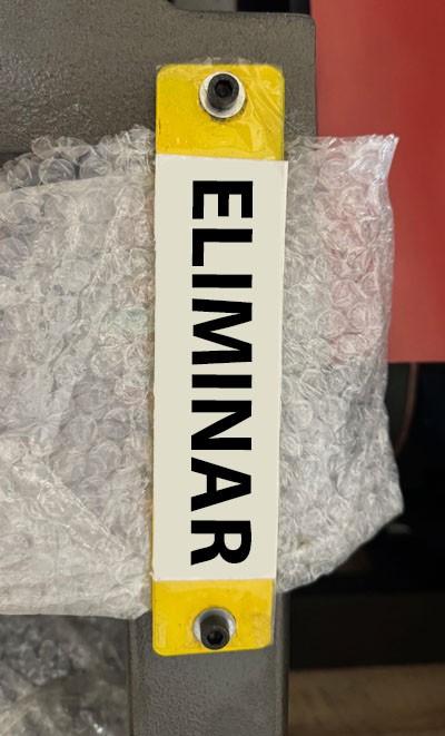
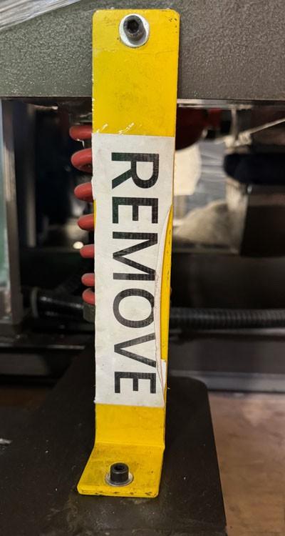
• Remove the two yellow 'L' pieces used to immobilized the vibration table.
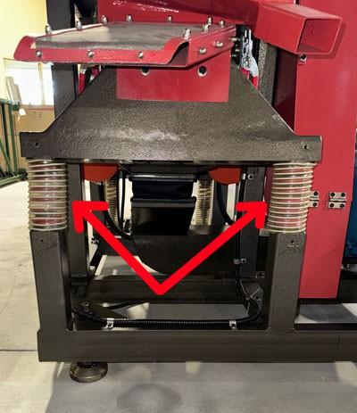
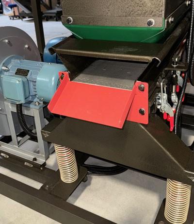
• Inspect the four supporting springs under the vibrating table for proper location and engagement. Some of them may have shifted in the shipping.
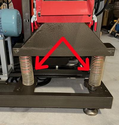
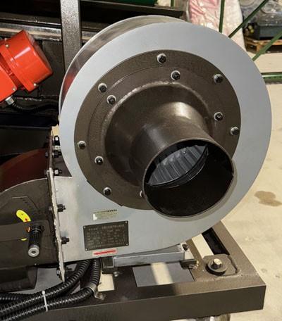
• In order to minimize shipping damage, some trays may have been removed from the granulator prior to shipping. Please make sure that the copper outlet, take two outlet, plastic outlet, blower inlet are all installed as shown.
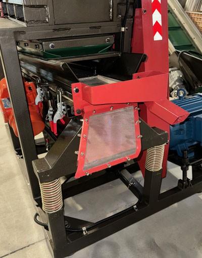
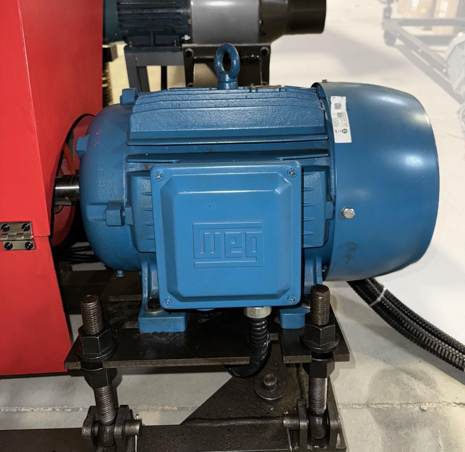
• Check the tension on the belts of the chopper motor. Adjust the bolts on the motor platform if necessary. DO NOT OVER TENSION THE BELTS. Over-tensioning may cause bearings to fail prematurely.
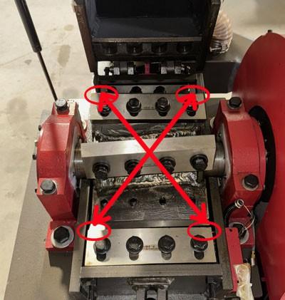
• It is now a good time to open the chopper and see how the blades are arranged, paying special attention to the clearance between stationary and rotating blades, when they are still new and sharp. This will help future blade installation. Refer to How to Operate the Granulator for details.
• A licensed electrician must be used to wire the granulator.
• The motors are prewired and have been pretested at our facility prior to shipping.
• The electrical panel needs to be mounted to the floor at a location that does not interfere with the movement of the operator. A dedicated ground wire, of 6 AWG or thicker, must be used to connect the electrical panel with the chassis.
• The chassis must be grounded to the ground using a wire that is 6 AWG or thicker.
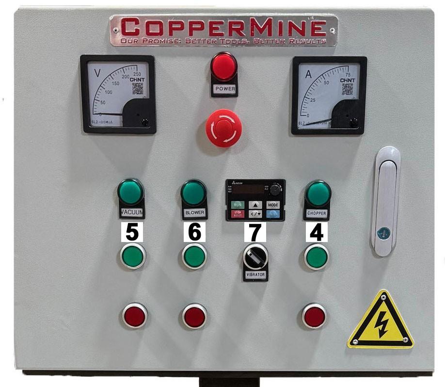
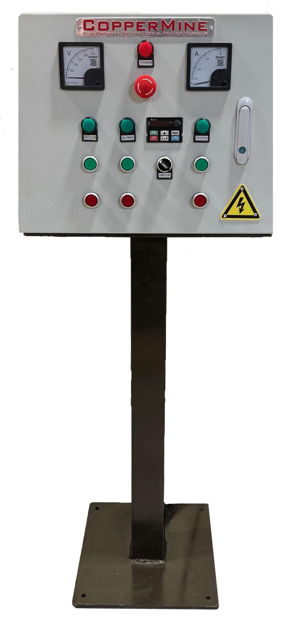
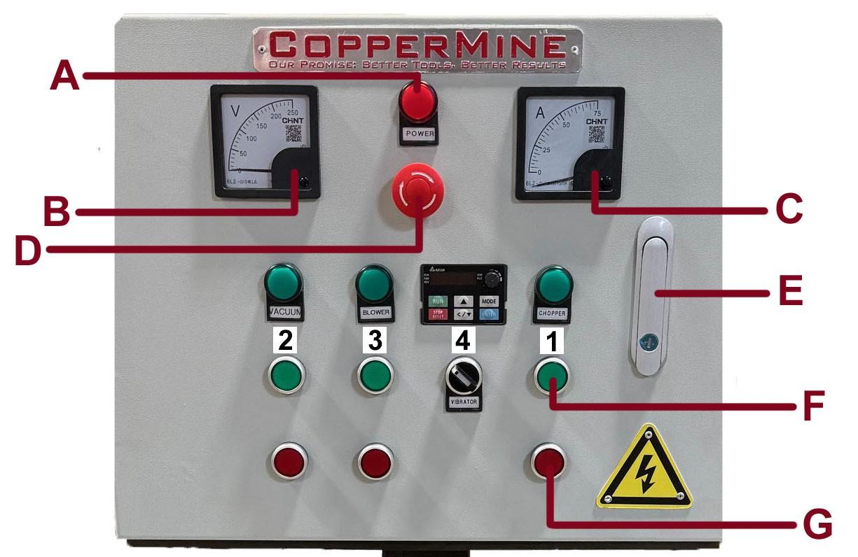
A: Panel power indicator light; B: Volt meter; C: Amp Meter; D: Emergency Stop; E: Door lever; F: ON button; OFF button; 1: Chopper; 2: Vacuum; 3: Blower; 4: Vibrator
(Caution tipping hazard)
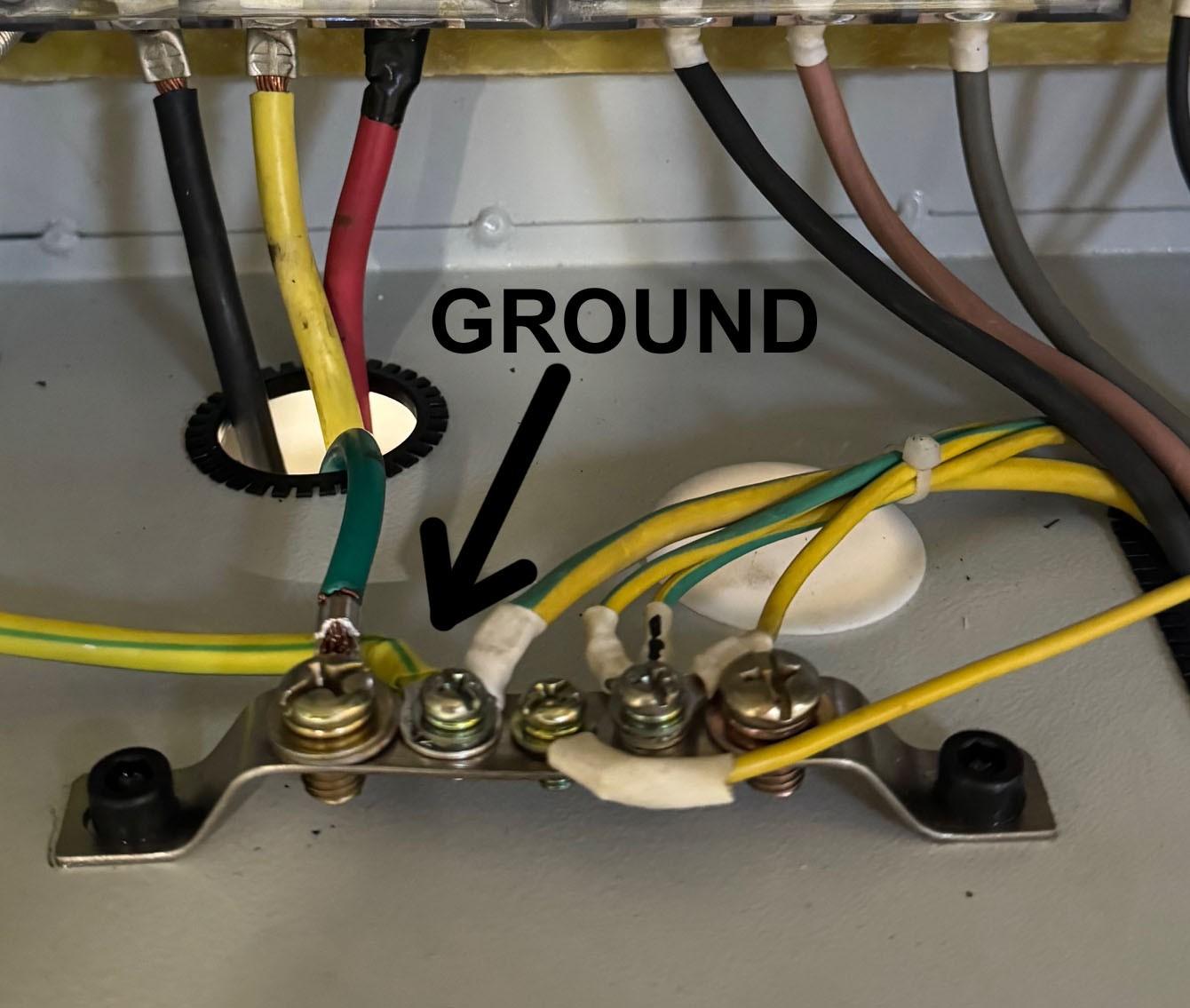
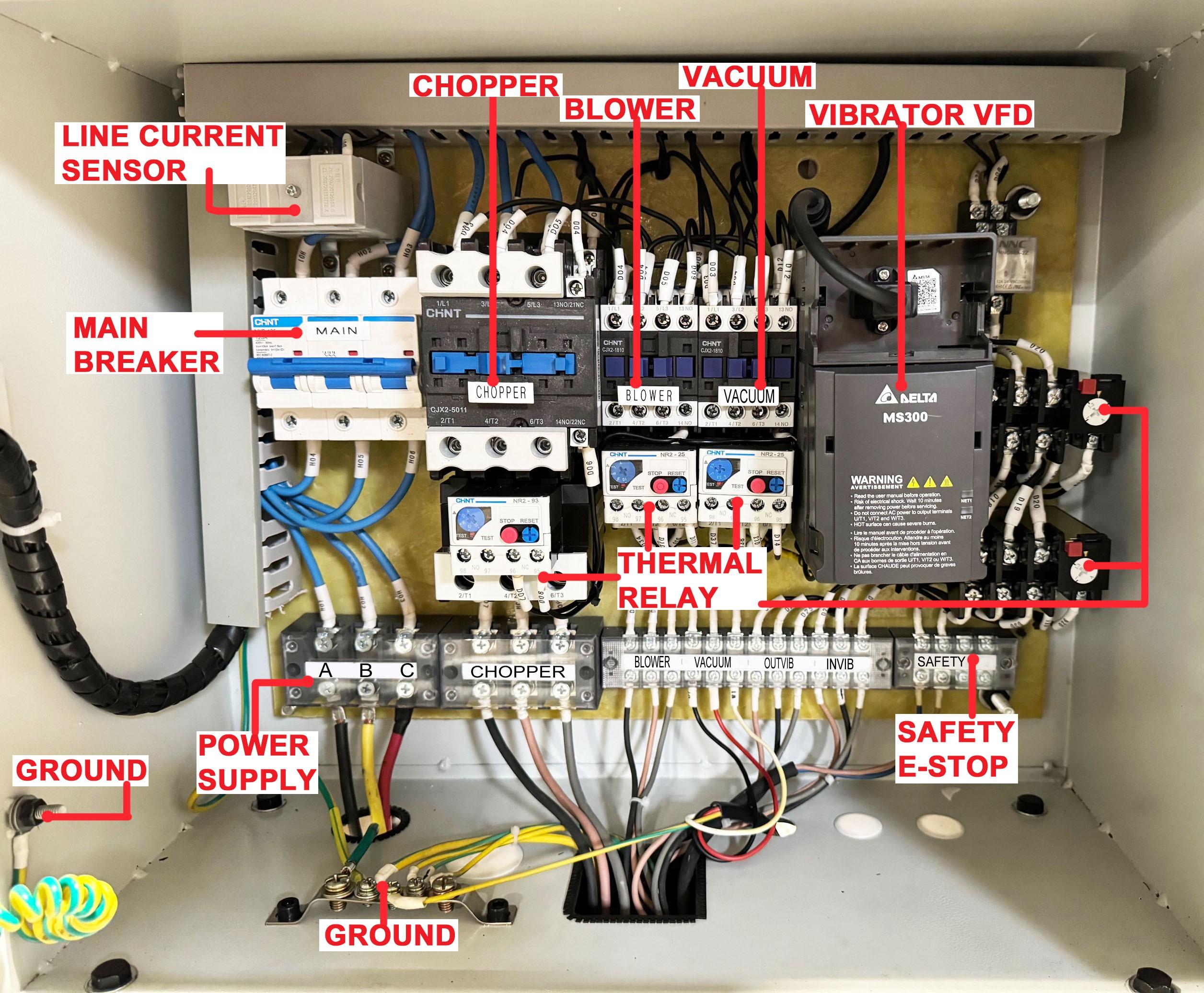
• Connect 4 AWG or thicker 3-phase power supply cable to the electrical panel. Twist the emergency stop button to disengage.
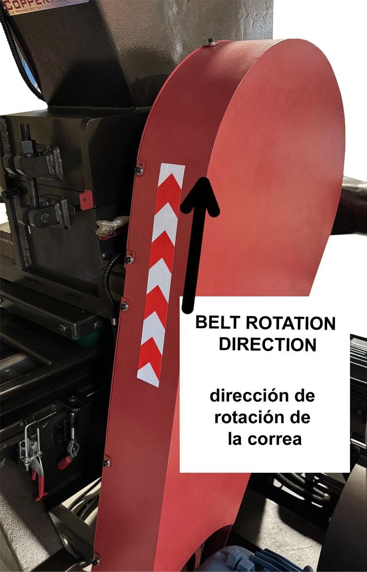
• Turn on the main breaker inside the electrical panel. Turn on the chopper motor briefly (refer to How to Operate the Granulator for turning on the machine). If the rotation direction is opposite to the indication on the belt cover, disconnect the machine from power at the power source and swap any two main power phases (seek electrician for assistance).
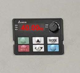
• Set the VFD (Variable Frequency Drive) to 40Hz. Turn on the vibrator briefly(refer to How to Operate the Granulator for turning on the machine). The vibrating table should vibrate smoothly with a low level of noise. If the vibrating table shakes significantly or produces loud noise, swap any two phases on any ONE of the vibrating motors.
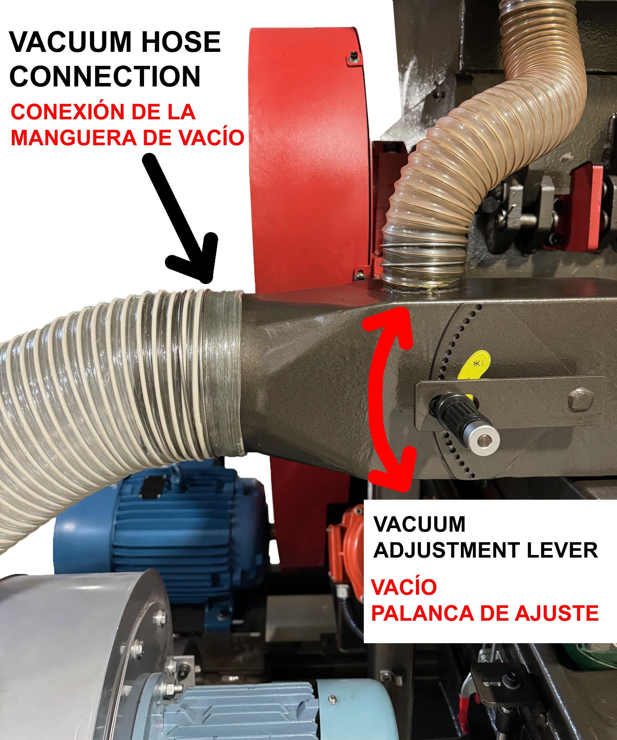
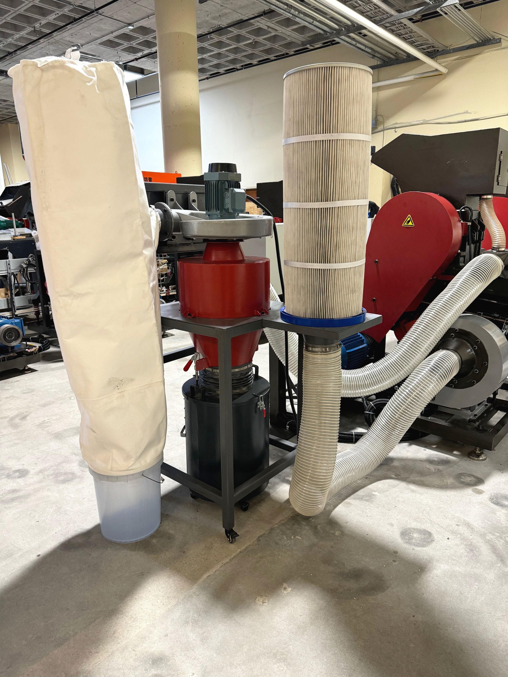
• Connect the dust collector to the vacuum outlet using a flexible duct. The dust collector removes any dust and lint from the chopper unit.
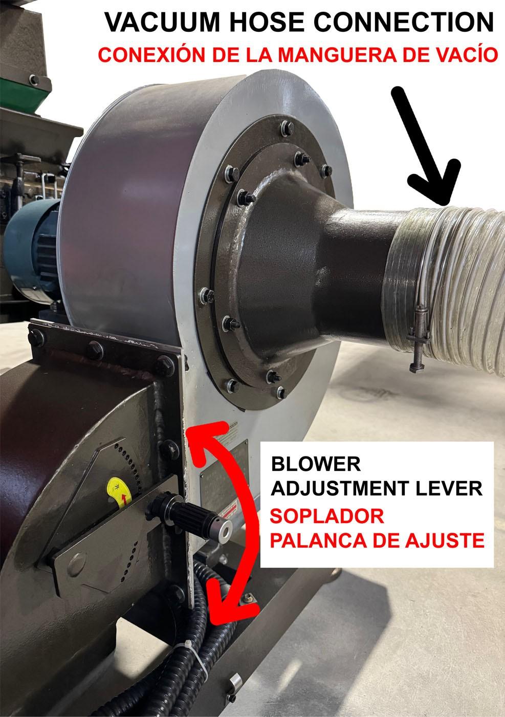
• Optional: use a duct (not included) to connect the blower inlet to an air filter or a location that is dust free. This is only necessary when the immediate surround area of the granulator has a higher level of dust, which overtime will clog the screen on the vibrating table, requiring a cleaning by compressed air.
Installing Your Cyclone Dust Collector Vacuum
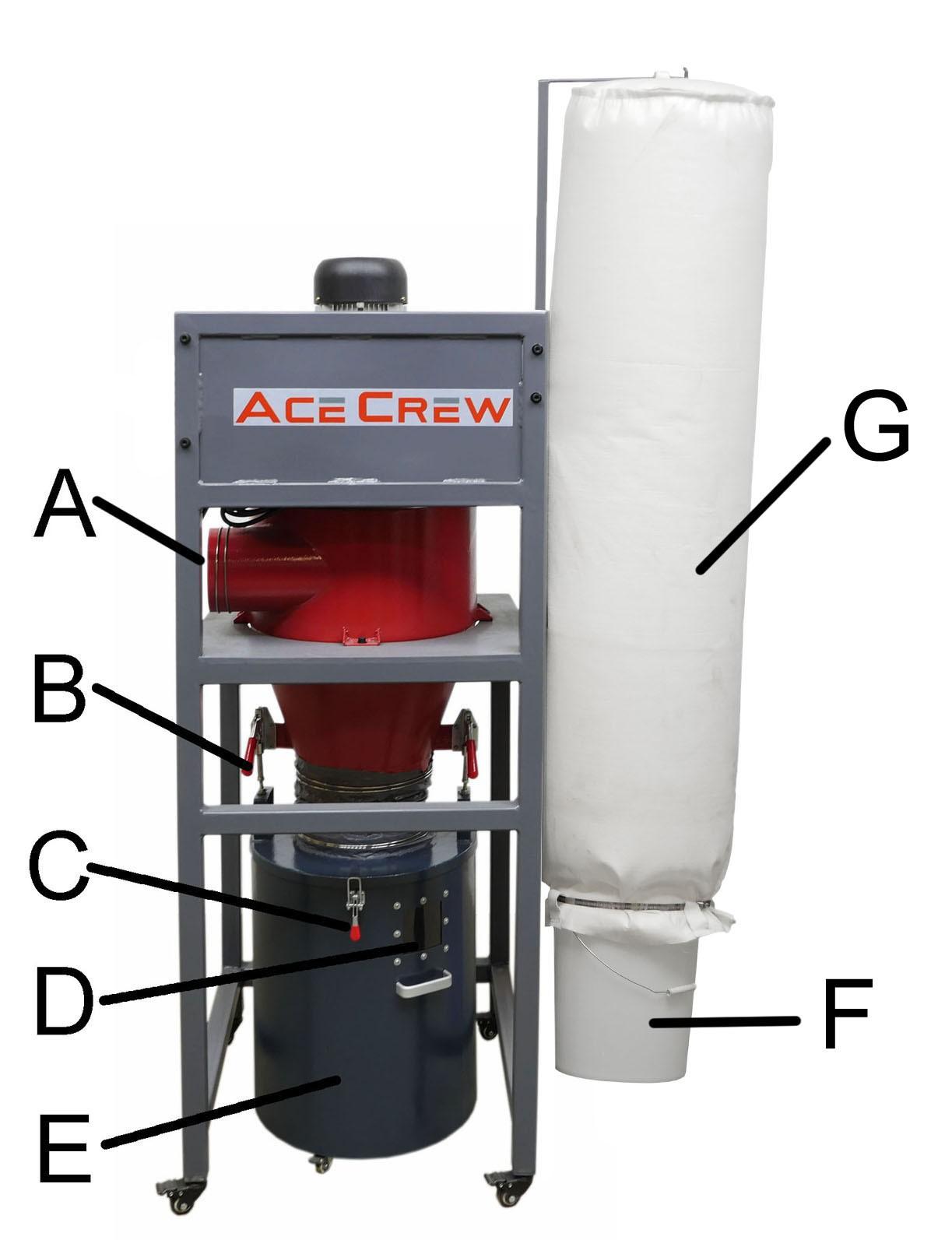
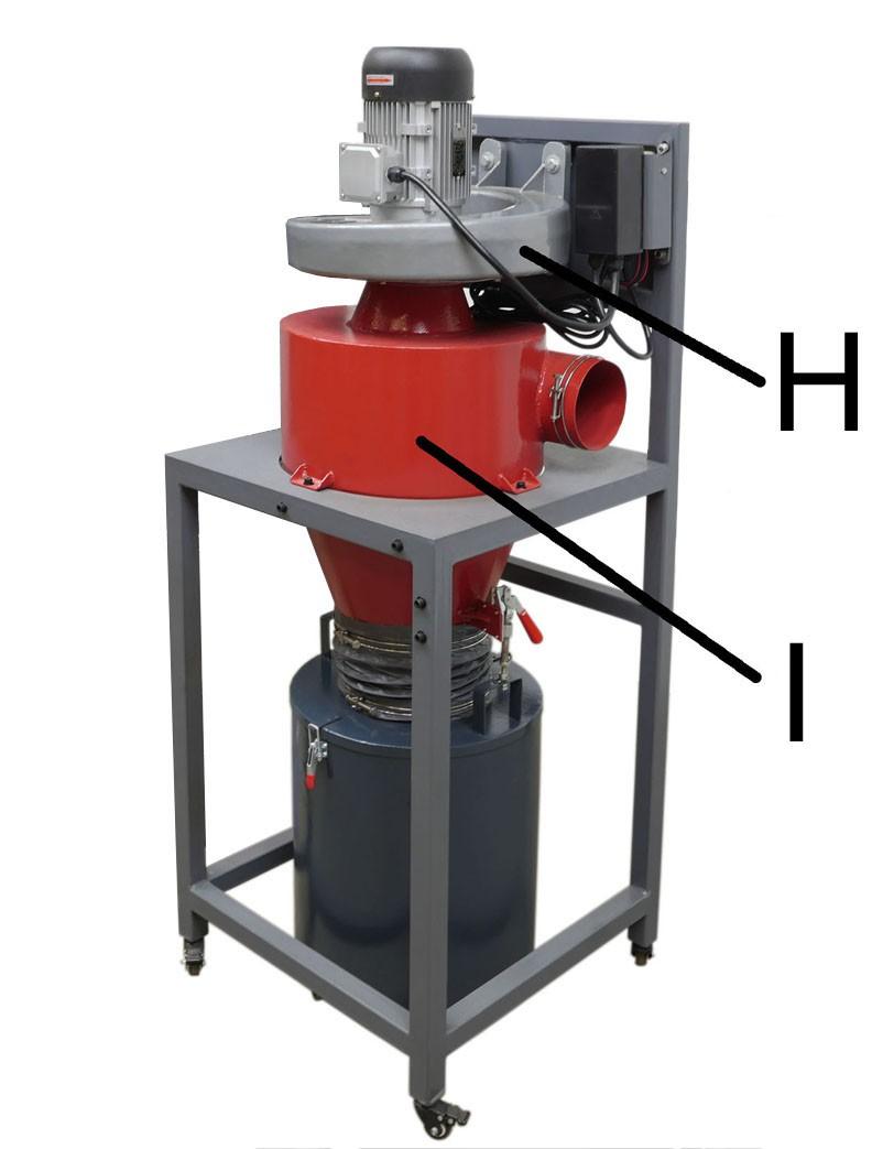
Know Your Vacuum
• A: Inlet; B: Quick Lever; C: Clamp; D: Sight Window; E: Drum; F: Bucket; G: Bag Filter H: Blower; I: Cyclone;
• Connect your vacuum hose from the granulator to the vacuum inlet.
• Optional: if an air filter was included with your purchase install the filter base onto the back of the vacuum frame.
• Connect the blower hose to the filter base as shown.
• The vacuum should already be pre-wired to your electrical panel.
• Refer to your (How to Operate Vacuum Instructions) for maintenance procedures.
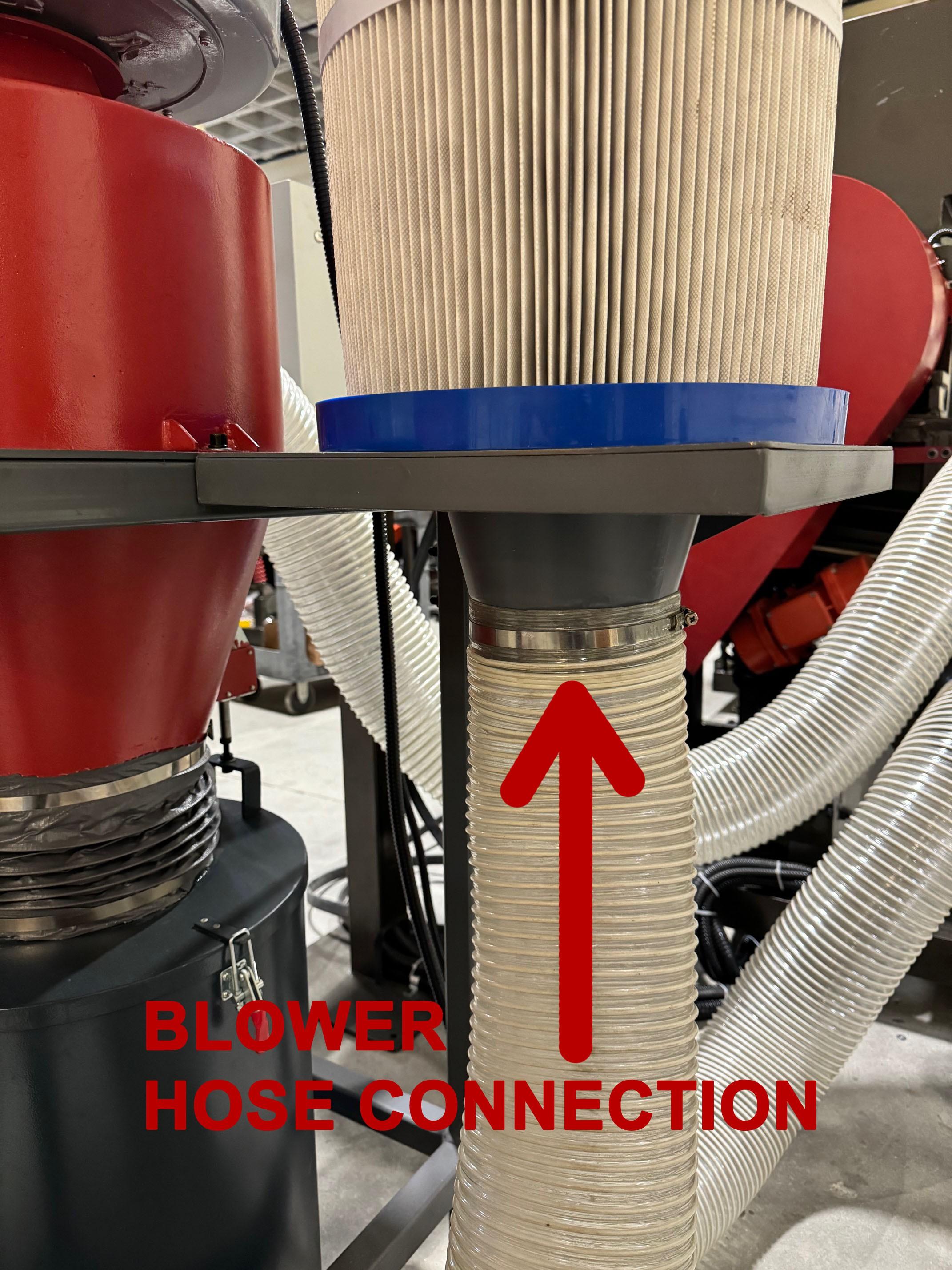
• SHUT OFF AND DISCONNECT POWER BEFORE PERFORMING ANY MAINTEANCE WORK
• Bag Filter(G) and Bucket(F)
The Bag Filter (G) and the Bucket (F) capture fine particles that escape the Cyclone (I). Frequent cleaning is recommend. Pat down the sides of the Filter Bag (G) to release particles that may be stuck to it. In extreme cases flip the Bag Filter (G) inside out and use a shop vac to vacuum it clean. Empty the Bucket (F) when it is full.
• Empty the Drum (E); WEEKLY OR IF FULL WHICHEVER COMES FIRST
• Empty the Bucket (F); WEEKLY OR IF FULL WHICHEVER COMES FIRST
The Drum (E) catches the majority of larger debris and particles. It needs to be emptied when debris reach the Sight Window (D)
• The machine shuts off by itself
The thermal relay inside the Motor Starter Box(A) shuts off the blower when it senses over current. Avoid the situations where the Inlet (L) is not connected to anything and/or the Canister Filter (G) is removed from the Cyclone (M), both of which will put stress on the Blower (K) and make it draw high current. Wait for a few minutes for the relay to cool down before pressing the blue rest button on the Motor Starter Box (A) and turning on the machine again.
• The machine is slowly losing its suction power. The Canister Filter(G) may need cleaning.
Operation
• Working Mechanism
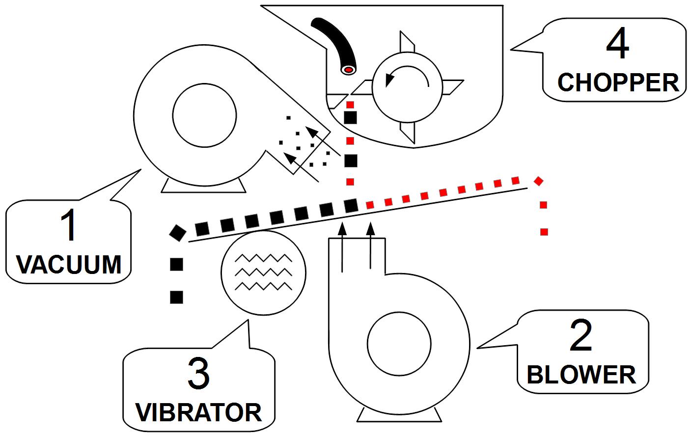
◦ The wire gets chopped so fine that the copper comes out of insulation automatically.
◦ On the slanted vibrating table, copper gets thrown uphill and plastic gets blown downhill.
◦ The vacuum collects any dust and lint.
• Refer to “Powering on the Machine” on Page 8
• Throw wires onto the input conveyor. The wires should run through the strip curtain by themselves. Thick wires should be broken into short sections and fed one at a time.
• It takes a great deal of power to chop the wires into fine pieces. So try to feed wires into the pre-shredder and granulator in a smooth and uniform fashion to reduce stress to the machine.
• Wires should be fed in small, loose handfuls. Always try to break big lump of wires into many small and frequent feedings. The current meter and sound of the chopper serve as a good indication of the chopping load.
• Hint: Because different types of wire may require different machine settings, presorting wires by type increases processing efficiency.
• DO NOT overfeed the machine. Overfeeding may lead to motor overload and may also overwhelm the vibrating table. If you notice an excessive amount of material coming out of the copper outlet this is a good indicator to stop feeding the machine. Wait until the vibration table outlet has cleared before continuing to feed the machine.
• NEVER STICK ANY BODY PARTS INTO THE CHOPPER OPENING.
Adjusting the VFD
• The VFD (Variable Frequency Drive) controls how many times the vibrating table vibrates per second. Faster speed lets copper to climb up the vibrating table faster but some plastic may also climb with the copper. Lower speed lets copper climb up slower resulting in longer separation time, which may be helpful for difficult-to-separate materials. However, too high or too low a frequency may cause the vibrating table to malfunction.
• 40 Hz is a good frequency for most wires, or starting point.
• You can adjust the frequency by turning the dial on the VFD located on the electrical panel.
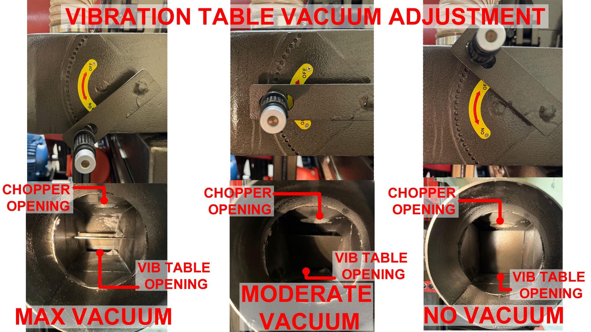
Adjusting the Vacuum (See page 28 for diagram)
• Adjust the damper such that all dust on the vibrating table is collected by the vacuum.
• Reduce the damper opening if fine copper strands come out with the vacuum exhaust.
• The granulator is typically quite forgiving towards the vacuum setting so no frequent adjustment is needed.
• It is typically recommended to set your damper opening to ON for optimal suction between the vibration table and the chopper.
Adjusting the Blower (See page 28 for diagram)
• The air flow of the blower plays a critical role in the copper and plastic separation.
• Higher flow results in cleaner copper but it takes longer time for the copper to climb uphill.
• Lower flow lets copper to climb up the vibrating table faster but some plastic may also climb with the copper.
• Adjust the damper for an optimum copper and plastic separation based on the nature of the wire being granulated.
• There should be a clear separation line on the vibrating table between the copper and plastic under the chopper area.
• Copper and plastic should exit the outlets smoothly without over-accumulation on the vibrating table.

• Copper should not exit the insulation outlet. Check your blower adjustment it may be too high and forcing the copper not to climb the vibration table properly.
• Insulation should not exit the copper outlet. If pure insulation pieces are exiting the copper outlet your blower adjustment may be too low.
• Check the outlets regularly to ensure good separation.
• Different wire types may require fine adjustments of the granulator, such as the blower damper and the VFD.
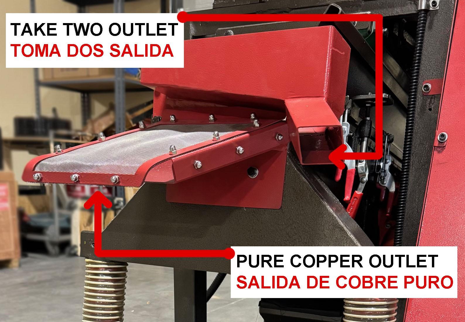
• The “Take Two” outlet is the right copper outlet when facing the front of the machine.
• Copper pieces that remain trapped in plastic, they will traveling along the top of the screen and come out through the Take Two outlet.
• It is recommended to simply feed them slowly (to avoid jam) back to the chopper for another round of chopping.
• The Take Two screen can be removed if the copper coming out of the vibrating table is clean enough. Machine Maintenance SHUT OFF THE MAIN
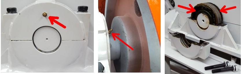
• The chopper bearings work under brutal conditions and should be lubricated once every 20 to 40 hours of use.
• As the lubricating grease runs through its life cycle, it becomes thinner and less effective. Therefore, the bearings require regular top off with grease.
• An abnormal temperature rise on the bearing indicates poor lubrication or over tensioned belts. Stop the granulator immediately and resolve the issue.
• Insufficient lubrication is the main reason for premature bearing failures, which is NOT covered by the warranty.
• Use high quality lithium-based high-temperature extreme-pressure grease, such as Mobil Delvac TM Extreme Grease, or equivalent.
• Connect a manual grease gun to the grease fitting. Apply 10 to 20 pumps while manually turning the shaft.
• DO NOT over-fill the bearings. Excessive amount of grease may lead to bearing seal damage and/or bearing over-heating.
• Repeat on the other bearing.
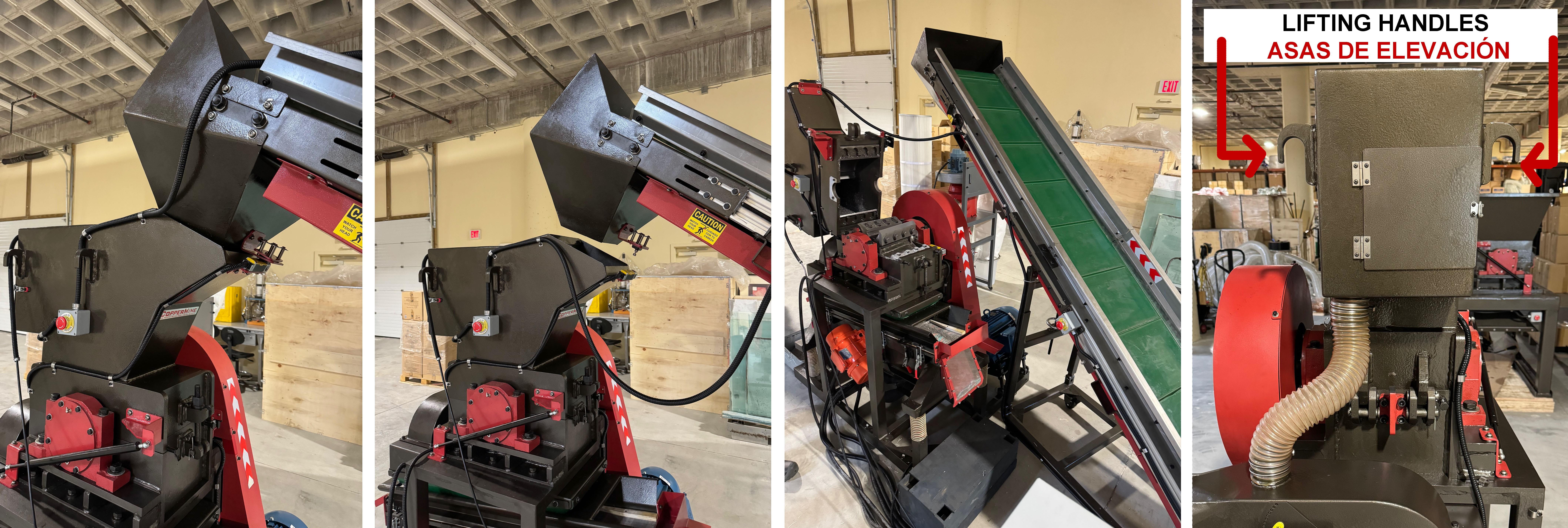
• Raise the output conveyor until the bottom of output hopper clears the top of the chopper opening. Move the conveyor to the left or right of the machine.
• Be careful to not pull or strain any of the power cords (if equipped).
• Loosen the chopper lock nut.
• CRUSHING HAZARD: DO NOT open the chopper lid from the front of the machine. Use the two handles located on the insulation outlet side of the machine to open and close the chopper lid. Failure to follow this procedure could result in severe injury.
• A torque wrench with a 24mm (15/16”) socket is required to loosen and tighten the blades.
• Use a piece of wood to stop the blades from rotating.
• It is recommended to remove and replace (1) blade at a time.
• It is strongly recommended, especially for new users, that a new set of blades is installed right after the old one is removed. This helps reduce possible confusion.
• When the blades get dull, copper pieces may become longer and begin to curl. More copper pieces may get trapped in plastic and exit through the Take Two Outlet.
• Sharpen the blade with a surface grinder. The angle of edge should be carefully maintained. Note: rotating blades have a different angle than stationary blades.
• Use coolant generously during the grinding process to prevent the blade from losing hardness.
• Newly sharpened blades may be so sharp that excessive amount of granulates come out at Take Two Outlet. This is temporary and will disappear shortly.
• CopperMine offers blade sharpening and blade exchange service. It is a cost-effective and faster alternative to getting blades sharpened by your local machine shop. Please contact us for details.
• Clear any copper or insulation debris around the blade area with a vacuum or air hose.
• It is now a good time to take out the chopper sieve for inspection and rotation (see next section for sieve rotation).
• Install two new stationary blades and hand tighten the bolts. Leave equal spaces from the side walls.
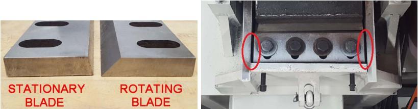
• Install one rotating blade and hand tighten the bolts.
• Carefully rotate the rotating blade near the stationary blade in the back of the chopper. Adjust both blades such that their cutting edges ALMOST touch each other when the rotating blade passes by the stationary blade. Although a gap that fits a single sheet of paper is typical, the cutting edges are allowed to SLIGHTLY touch each other, as well. The clearance between the two blades should be as small as possible and uniform along the length of the blade. Use a small hammer to knock on the blade slope to nudge it backward.
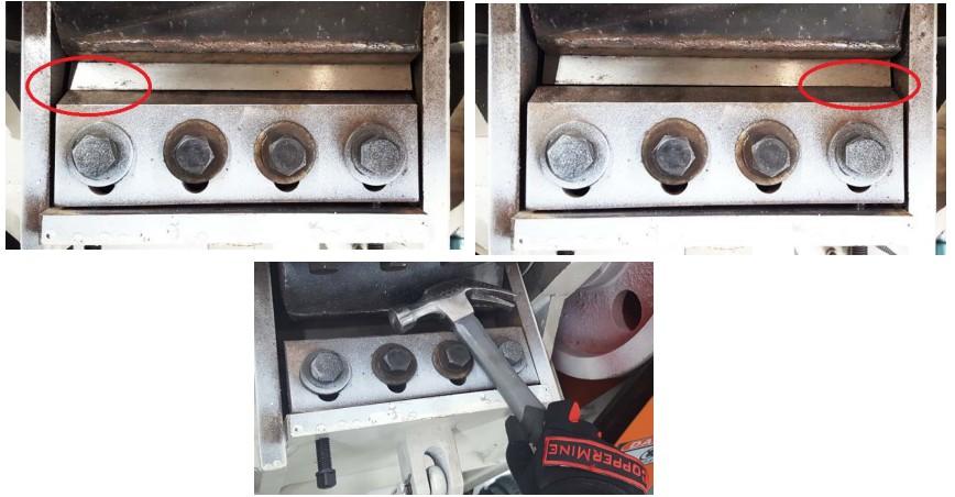
• Turn the bolts behind the stationary blade to push it forward. One can also use a screwdriver to pry the back of the blade to nudge it forward.
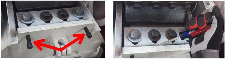
• Tighten bolts on both blades progressively using a torque wrench. Blade may shift when the bolts are tightened. Rotate the blade and check for clearance. Nudge the blade if necessary. The final torque on the bolt should reach 150 Lbs.
• Now the back stationary and one rotating blade are done. They should be kept tightened and used as reference to install the remaining blades.
• Carefully rotate the rotating blade near the stationary blade located in the front of the chopper. Adjust the stationary blade such that its cutting edge meets that on the rotating blade the same fashion as the back stationary blade does. Tighten the front stationary blade.
• Now all two stationary blades are done.
• Install a second rotating blade and fine tune its position relative to the two stationary blades and tighten its bolts.
• Repeat on the remaining three rotating blades.
• After all seven blades are installed, rotate and verify that each rotating blade passes either stationary blade with the same level of clearance.
• After extensive use, some holes on the chopper sieve may be blocked by copper pieces. The sieve can be taken out for cleaning after removing the front stationary
blade.
• Open the chopper and remove the front stationary blade.
• Pry up the sieve using a slot screwdriver and start pulling out the sieve.
• Hand turn the rotating blades may help scoop out the sieve.
• Clean the holes with compressed air.
• Use compressed air to blow off any debris that may have fallen on the bracket where the sieve sits on.
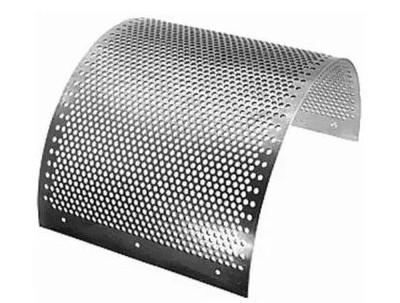
• It is recommended to rotate the sieve 180° every time a blade change or sieve cleaning is performed. This helps the sieve wear evenly.
• Gently drop the new sieve to the floor to open it up if it is curled up too much.
• Put the the sieve in place. At the bottom of the curve, the gap between the sieve surface and blade edge should be 1/8” to 3/16”.
• If the end of the sieve sticks out and doesn't allow the stationary blade to sit flat, grind off any excessive edge on the sieve.
• Fine dust may collect on the under side of the vibrating table screen. As a result, more blowing power (larger blower damper opening) is needed for separation.
• When even the highest blowing power (blower damper fully open) can not achieve a good separation, the vibrating table screen needs a cleaning.
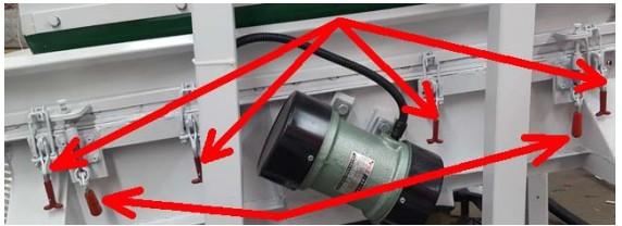
• Loosen the quick-clamps and push the quick-pushes to remove the screen and blow with it compressed air.
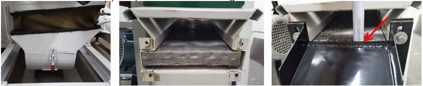
• Open the door at the bottom of blower duct and check for any fine copper pieces that may have collected(shown below). Use a Shop Vac to remove them.
• After re-installing the screen (as shown below), tighten the quick-clamps.
• Sometimes it is desired to keep the plastic on the vibrating table for a longer time in order to recover as much fine copper as possible. The edge of the Plastic Outlet can
be set 5mm (3/16”) taller than the vibrating table.
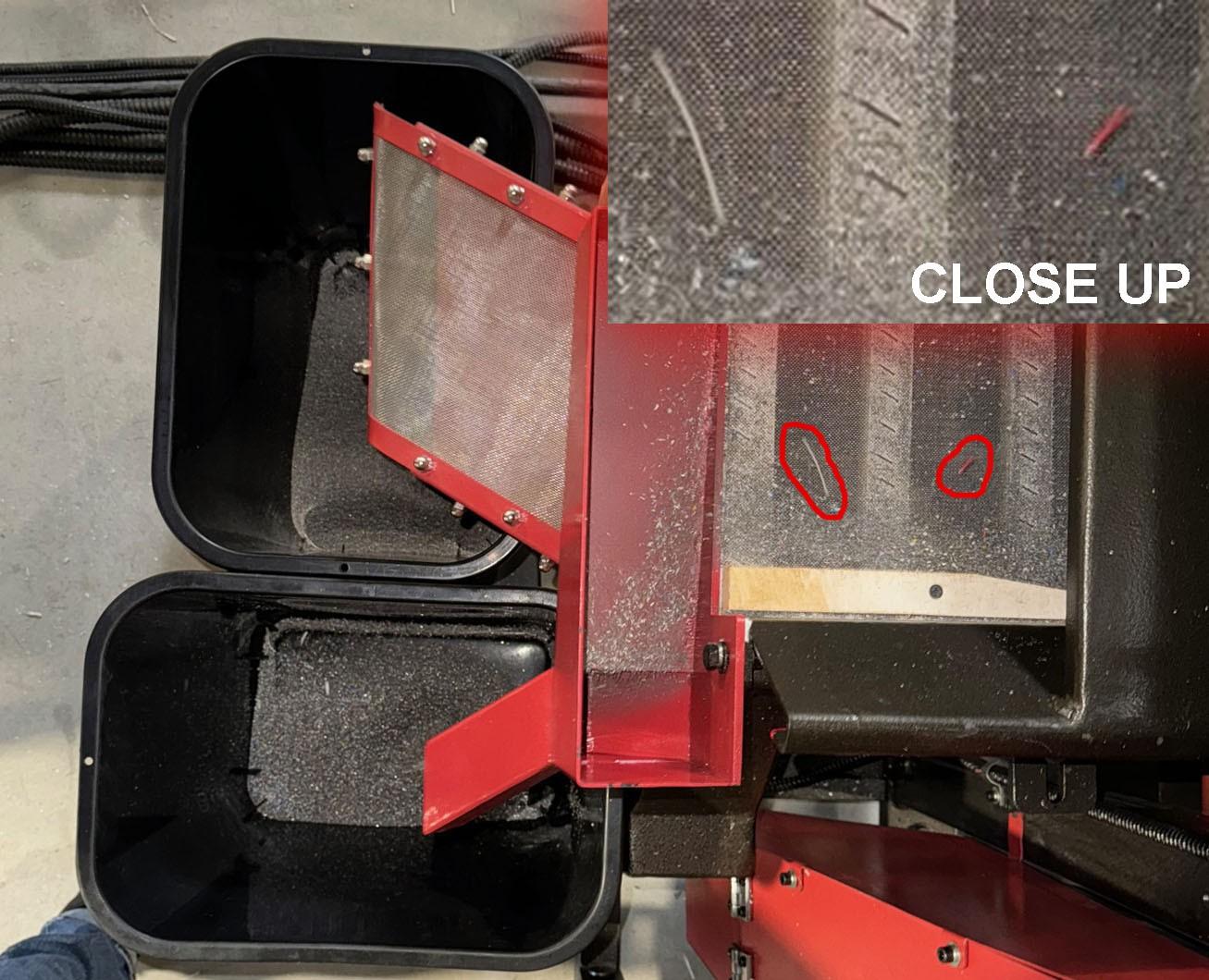
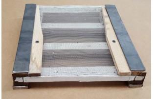
• The Take Two Screen allows copper to drop down while keeping any copper-plastic combo on it. Any objects (e.g. long strands of copper) that are stuck to the screen need to be removed.
• Use a Shop Vac and a brush to clear any debris.
• The Take Two Screen sits between two wooden brackets.
• Loosen the quick-clamps under the vibrating table and pull out the Take Two Screen.
• Remove the staples and old screen. Staple the new screen on the frame.
• Use foam tape, if necessary, to seal the gap on either end of the Take Two Screen to avoid cross contamination between Copper and Take Two.
• After extensive use, the flexible connection between the vibrating table and the blower duct may be torn. Replace it with any fabric that is strong and dense.
• Open the door on the back of the chopper at the end of work day to remove any lint that has been collected near the vacuum opening.
• Open the door at the bottom of the vibration table and vacuum out any decries that may have fallen into the pipe.
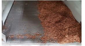
• When I first feed wires, the copper hovers on the vibrating table but won't come out?
◦ The vibrating table needs about 5-10lbs of copper and plastic on it to function properly. A few dozen of pounds of wire may have to be fed to the chopper before copper and plastic start coming off the vibrating table at a normal pace. Some quantities of copper and plastic may remain on the vibrating table after wire feeding is stopped, as well.
• The Copper does not spread evenly on the vibrating table?
◦ The granulator may need to be leveled if copper tends to gather on one side of the table as it climbs up. Use the feet on the granulator chassis to level the machine.
◦ Be sure to level the vibration table, and not the frame of the machine.
• I am finding that plastic pieces come out from the Copper Outlet during initial power-on?
◦ When the granulator is first turned on, the remnant plastic on the vibrating table may climb up and come out from the Copper Outlet. Vacuum or blow the vibrating table clean before power-on if necessary.
◦ You may also delay powering the blower and vibrator until enough material has built up on the vibration table.
• Plastic pieces come out from the Copper Outlet during power-off?
◦ When the chopper is gradually emptying itself during the power-off process, more plastic pieces may start to come out from the Copper Outlet. If the copper purity is a concern, switch to a different copper container to collect copper right before the power-off process.
• What happens if there is a power outage during operation?
◦ When the chopper loses power before all granulates have passed the chopper sieve, either because the power was turned off too early or an unexpected power outage, the chopper blades may not be able to start rotating again when the power is restored. The remaining granulates in the chopper has to be scooped out manually before the blades can rotate freely again. Please refer to Cleaning Chopper Sieve for more information.
• What happens if the machine Jams?
◦ The chopper may get jammed when too much Take Two granulates are fed too quickly. Shut off the chopper immediately to avoid permanent motor damage. Refer to Power Outage During Operation for clearing the jam.
• Why does the blower damper have to be opened wider and wider to achieve a good copper/plastic separation?
◦ The screen on the vibrating table may need a cleaning. Dust that enters the blower has collected on the under side of the screen, which limits the air flow. Remove the screen and use compressed air to blow in opposite direction at the screen to dislodge the dust. If the screen gets clogged frequently, a duct can be used to draw air from a dust-free area or from an air filter.
• Why does the vibrating table shakes wildly during power on and power off transition?
◦ It is normally for the vibrating table to shake briefly before it comes to steady vibration or rest. When the vibrating table is working properly, the vibrating is fast, in small movement range and stable. Prolonged shaking may indicate that one of the two vibrating motors is malfunctioning.
• Why am I finding very thin copper strands in the plastic outlet?
◦ The vibrating table can effectively separate copper as thin as 3 mil (1 mil is one thousandth of an inch) from plastic. For copper strands thinner than that size, some of them may start coming out through the plastic outlet. The thinner the copper, the more likely it may get blown downhill the vibrating table. Wires with such thin copper strands are rare and should be processed by other means.
• Why is there a large amount of a combination of copper and plastic coming out through the Take Two Outlet?
◦ Large amounts of copper-plastic combo, sometime together with longer than normal copper pieces, may indicate dull blades. Check the sharpness of the blades and re-sharpen them if necessary.
• There is fine copper powder in plastic outlet, why?
◦ The chopper does generate small amount of copper powder. Because of its light weight and small size, it is normal to have some copper powder at the plastic outlet. For processing thicker wires, Thick Wire Option should be used to avoid excessive chopping on the copper. Please contact us for technical advice.
• Why is there steel pieces in my copper?
◦ Any iron and steel debris should be picked out before wires are fed in the chopper. Otherwise, the blades may get damaged and the copper may be down-graded when magnetic debris are detected in the copper. To remove small amount of iron and steel from the copper outlet, permanent magnets (not supplied) may be lined on the copper outlet tray.
• CopperMine Tools warrants to the original purchaser that for a period of one year from date of purchase, all parts and components, excluding blades and belts, of the product are free from defects in materials an workmanship. To take advantage of this warranty, the defective part must be returned to our facility in Boston with shipping charges prepaid. We will repair or replace the part at our election and return it at our expense. Each product has a unique serial number and the original sales information is kept at our facility to serve as warranty record. Warranty registration is not required.
Spare & Replacement Parts
• Please use genuine CopperMine parts for best results
• Visit www.copperminetools.com or email sales@copperminetools.com for details
• If you have questions or need assistance please contact our technical support at 1-855-643-7491. We are available Monday through Friday 8 AM to 4:30 PM ET.
• Email: help@copperminetools.com Website: www.copperminetools.com
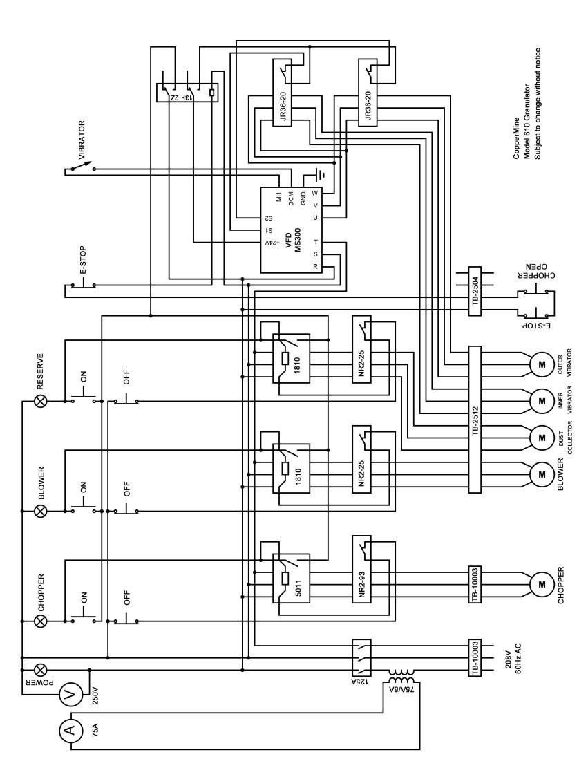
Electrical Schematics
Machine: CT-610 3-PHASE
Machine: CT-910/ 920 3-Phase