9 minute read
A Subaru Legacy with Redundant EFI. Ken Lehman does an out


Story and photos by Ken Lehman, Ontario, Canada
Advertisement
klehman@albedo.net
As of this writing, I have 140 hours on an internally stock 1997 Subaru EJ22 hanging from the nose of my Murphy Rebel experimental aircraft. Total time includes a meandering 5,000 mile trip I took this past summer that took me through the Canadian Rocky Mountains on my way to the EAA Regional Fly-in at Arlington, Washington. We were a flight of four Rebels, loaded with camping equipment during that 58 flight-hour adventure.
PERFORMANCE
The Lycoming O-320 plane burned $2,500 worth of leaded aviation fuel (100LL) while the Subaru and two Rotax 912 powered Rebels each burned $1,000 or less of automobile fuel (mogas). Interestingly, my Sube could match the Lycoming powered machine’s performance for takeoff and climb but, then at an average 17 liters per hour (4.5 gph), pretty much match the lighter 912 powered machines for economy cruise. My engine is set up to make a conservative 120-hp but that’s about all the fixed -pitch Lycoming does during takeoff and climb, although he definitely cruised faster.
DONOR ENGINE
The engine that we used was from a brand new (but damaged) vehicle, so I didn’t split the case. However, the first engine purchased had 40,000 km on it and although it had also been pulled from a wreck, opening it revealed a bad rear main bearing so we chose not to use it for that reason and others.
ELECTRICAL REDUNDANCY
Our installation features two electrical systems powered by two small 9 ampere-hour (AH) sealed batteries that are momentarily connected in parallel for starting even though one alone is capable of the cranking chore. A 20 amp John Deere permanent magnet dynamo (generator) and a 40 amp Nippondenso “one wire” alternator keep them charged.
EFI
The 1997 engine runs on a stock 1991 Subaru electronic fuel injection (EFI). However, believing that established automotive reliability can’t always be counted on with the transplanted engine and one-off wiring, I opted for a second (redundant) backup EFI system. The goal was that no single electrical failure could stop the engine. A second set of multi-point fuel injection (MPFI) injectors were installed into bungs welded to the intake manifold, operated by a MegaSquirt® EFI Controller kit. Two switches supply power to the respective set of injectors. Interestingly, if both switches are on the engine keeps running (although ridiculously rich). For more info on the MegaSquirt EFI system, please see the side piece at the end of this article.
The stock Sube EFI runs about 800° C (1,472° F) EGT at full throttle and about 820° C (1,508° F) in cruise. Initially those temps seemed high but by running on the backup EFI and manually adjusting the mixture I have confirmed that the stock system is always running at peak EGT in the 4,000 to 4,400 RPM range in which I cruise. It’s no surprise when you realize that the stock (automotive) system is targeting 14.7:1 stoichiometric mixture to keep a catalytic converter happy. It seems that I can reduce fuel consumption about 5% (and lower EGT a bit) by running lean of peak on the backup EFI in cruise, but that requires fiddling with the manual mixture
Alternator
Dynamo
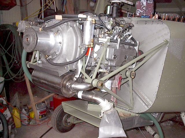
This end of the engine fits neatly against the firewall and clearly shows the location of the redundant charging systems, the cam-driven vacuum pump and the crank position sensor.
knob on the backup computer. Once you get used to not playing with mixture and carb heat or closely watching engine temps for peaks and shock cooling, it is more enjoyable to just fly on the OEM system and ignore the engine unless the engine information system (EIS) monitor calls attention to something.
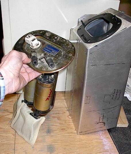
A high pressure fuel valve allows for feeding one or both fuel rails. While I have two submerged fuel pumps in a two-gallon, gravity-fed header tank, they each have external check-valves as well. The pumps also have internal check valves but a rubber hose failure between the pump and the tank outlet could cause loss of fuel pressure without external check valves.
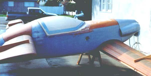
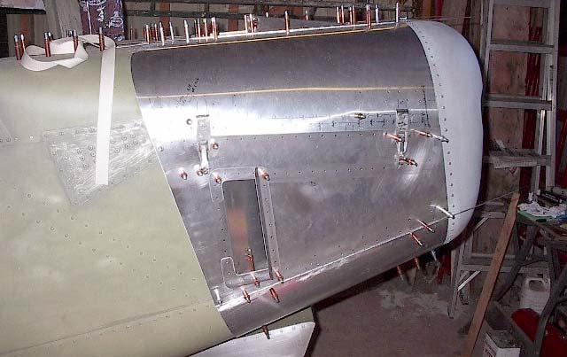
INDUCTION and COWL
Combustion air is taken from inside the cowl and unfortunately runs about 30° C above OAT. I’d like to get that cooler but haven’t been able to get cooler air up there without cutting a hole in the cowling door, which I’m reluctant to do. The cowl is fairly tight to minimize drag. Air enters through two, 3-inch dia. holes (roughly) and exits through side ramped vents. You may notice a reverse air scoop on the top of the cowl. That was to let hot air out after shutdown and to give a bit more clearance to the TBI while avoiding rain ingestion. A tuft confirms that air flows out of it on the ground but into it during flight due to pressure build-up ahead of the windscreen.
When it came to aluminum manifold modifications, I found that TIG welding was a joy to learn and use and cheaper than expected. Some have claimed very high weight for the cast aluminum manifold but I recall it being only 4 or 5 pounds when stripped and I estimated the runner length to be tuned about right for me.
REDUNDANT IGNITION
The primary ignition utilizes the stock Sube system, but the secondary system is from a mid-80s Chevrolet Cavalier. Interestingly, despite being a distributorless system (like the primary Sube ignition), when one coil failed in ground testing the backup ignition would still run the engine on three cylinders with the primary ignition off. The H.V. (high voltage) system is a bit complex as dual polarity, high voltage coil joiners are used to feed either or both ignition systems to one spark plug per cylinder. Two MSD joiners are used for normal polarity and high voltage diodes have been potted into a 6-cylinder distributor cap for the other polarity.
The Chevy crankshaft position sensor (seen in the photo to the right, opposite page) overhangs the stock crankshaft harmonic damper. It is set for 10° BTDC static. The Chevrolet Distributorless Ignition System (DIS) module advances with RPM to about 25° before TDC in cruise. That is not as much advance as the OEM system but it is adequate for starting and maintaining flight. It is also in the ballpark for running a 40-hp shot of nitrous in the future for operating on floats out of small lakes.
The Chevy DIS runs all the time and there is a switch to provide +12 volts to the Chevy coils when their output is desired. The engine does not miss a beat when switching between EFI systems or ignition systems on the fly.
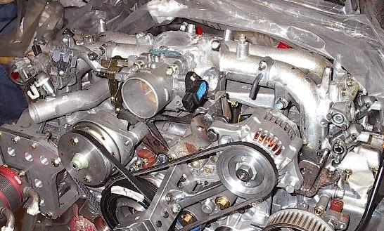
Two-gallon aluminum header tank with redundant submerged electric fuel pumps plumbed in parallel. The image above shows the modified manifold, including the addition of injector bungs. Note too the oversized pulleys on the alternator and dynamo, designed to prolong life while fitted to a relatively highrevving engine.
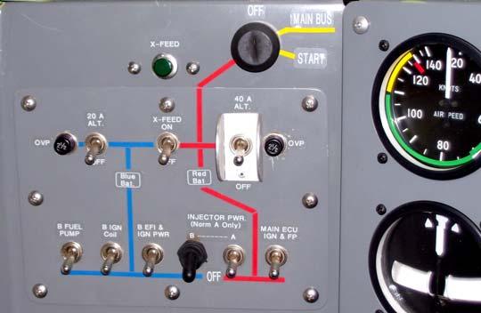
The description of the redundant nature of the systems seem complicated at first, especially once paired with the switchology involved, but it takes only a few seconds of viewing the panel and the way the switches are laid out to understand the simplicity it actually carries. COOLING SYSTEM
Keeping the engine cool has been a problem-free experience. Even in 37° C (98.6° F) OAT weather, the water temperature will not go above the thermostat setting while on the ground. Normally the water temp is controlled by the thermostat and for awhile I was sure I had overbuilt the cooling system. However, in heavy, extended climbs to 8,500 ASL (12,500 density) such as coming out of Golden, B.C., in very hot weather, the water will climb to 100° C (212° F) so it looks like we’ve got it nailed. I always climb at full throttle but I can see why a 3" thick radiator or a bit larger one might be appropriate for those with a modified cam or who cruise at full throttle in warm air temps. The radiator sits under the fuselage and is two inches thick with a face area of 22" wide by 6” tall. I had to consult Kuchemann’s book The Aerodynamic Design of Aircraft before I felt that I was even beginning to understand a liquid-cooled system for aircraft engines. I believe the cooling chapter is available on the Web. I recommend Kuchemann because the last serious research was probably done during WWII and little has been learned since outside of the experimental-aviation community. There are just too many conflicting examples of modern theories and installations that sometimes work and sometimes don’t. My radiator intake scoop is far enough from the propeller to accept a lot of air during ground operation. It’s also far enough behind the prop to avoid blade interference if indeed there were any. The bottom of the intake duct goes straight to the bottom of the radiator but the top of the duct conforms to streamline flow as described by Kuchemann. That means it curves up to the top of the radiator fairly suddenly as it meets up with the radiator, much like the bell of a musical instrument such as a tuba. The goal was good cooling with no more parasite drag than an air cooled engine.
There is a cockpit-adjustable exit damper (the equivalent of a cowl flap) about two feet behind the radiator but it doesn’t do much as the thermostat controls the water temperature nicely. The cockpit-adjustable feature is probably not worth the effort for a 100 MPH airplane. One-inch silicone hoses are routed to and from the radiator. There have been reports of problems using smaller hoses for remotely located radiators so I opted to not take chances. A small steam vent has been fitted to the top water manifold exiting the engine and it continuously flows back to a pressure sensor through 5/16 coolant hose and to a translucent plastic sealed reservoir from a Volvo. Originally it also flowed through the throttle body to keep it warm but I have since bypassed it. No swirl pot was needed in the car or the airplane and there have been no issues with trapped air.
I have a Modine oil to water heat exchanger which helps warm the oil after cold weather starts. I have seen 120° C (248° F) crankcase oil temperatures during the aforementioned hot weather climbs but that’s fine for 5W50 synthetic oil. The water output from the Modine goes to a large cabin heater on the forward side of the firewall. It turned out to be ridiculously oversized for cabin heating but I have the option of rearranging to vent air from it overboard if further cooling is needed after retrofitting floats to the Rebel.
Few pilots fly in the winter here but I find they are still preheating while I’m warm and airborne. I ended up fitting a fan to the cabin heater but with the fresh air intake located below the spinner the fan is simply not needed, even on the ground. Occasionally a small defrost fan blowing air up through the glare-shield and onto the windscreen is useful though. The plan was to have the floats finished for next summer but we are having so much fun flying to little grass strips that I think we’ll keep the plane on wheels for another year.