
193 minute read
Contents

from MDT BMP manual
by ClearH2o

2. Acronyms .................................................................................................. 3 3. Introduction .............................................................................................. 5 4. MDT Contract Responsibilities................................................................... 7 5. Storm Water Regulations .......................................................................... 9 6. Erosion & Sediment Control Principles .................................................... 11 7. BMPs by Application................................................................................ 15 8. BMPs by Category.................................................................................... 17 Construction Site Planning (CP)............................................................................19
CP-1 Scheduling ................................................................................................... 19
Advertisement
Temporary Soil Stabilization (SS)..........................................................................23
SS-1 Preservation of Existing Vegetation/Vegetated Buffers............................... 23 SS-2 Mulch Cover................................................................................................. 27 SS-3 Temporary Seeding ...................................................................................... 31 SS-4 Erosion Seeding............................................................................................ 33 SS-5 Soil Binders................................................................................................... 35 SS-6 Rolled Erosion Control Products .................................................................. 39 SS-7 Surface Roughening ..................................................................................... 45 SS-8 Wind Erosion Control................................................................................... 49
Run-on and Runoff Control (RC)...........................................................................53
RC-1 Earth Dikes/Drainage Swales/Lined Ditches................................................ 53 RC-2 Outlet Velocity Dissipation Devices............................................................. 57 RC-3 Temporary Slope Drains .............................................................................. 61
Temporary Sediment Control (SC)........................................................................67
SC-1 Silt Fence...................................................................................................... 67 SC-2 Desilting Basin.............................................................................................. 73 SC-3 Sediment Trap ............................................................................................. 77 SC-4 Check Dams ................................................................................................. 81 SC-5 Dugout Ditch Basin ...................................................................................... 87 SC-6 Fiber Rolls .................................................................................................... 91 SC-7 Compost Socks............................................................................................. 97 SC-8 Brush Barrier.............................................................................................. 103 SC-9 Sandbag Barrier ......................................................................................... 107 SC-10 Gravel Bag Berm ...................................................................................... 111 SC-11 Rock Filter Berm....................................................................................... 115 SC-12 Inlet/Outlet Protection ............................................................................ 119 SC-13 Stabilized Construction Entrance/Exit ..................................................... 127 SC-14 Stabilized Construction Roadway ............................................................ 131 SC-15 Entrance/Outlet Tire Wash...................................................................... 133
Snow Management (SM) ...................................................................................137
SM-1 Snow Management .................................................................................. 137 SM-2 Snow Accumulation Management ........................................................... 139 SM-3 Freeze Reduction...................................................................................... 141
Good Housekeeping (GH)...................................................................................145
GH-1 Vehicle and Equipment Cleaning .............................................................. 145 GH-2 Vehicle and Equipment Fueling ................................................................ 147 GH-3 Vehicle and Equipment Maintenance....................................................... 149 GH-4 Street Sweeping and Vacuuming.............................................................. 153 GH-5 Material Delivery and Storage .................................................................. 155 GH-6 Material Use ............................................................................................. 159 GH-7 Stockpile Management............................................................................. 163 GH-8 Spill Prevention and Control..................................................................... 167 GH-9 Water Conservation Practices .................................................................. 171 GH-10 Paving, Saw Cutting, and Grinding Operations ....................................... 173 GH-11 Illicit Connection/Illegal Discharge Detection and Reporting ................. 177 GH-12 Potable Water/Irrigation ........................................................................ 181
Waste Management (WM) ................................................................................183
WM-1 Solid Waste Management....................................................................... 183 WM-2 Hazardous Waste Management ............................................................. 187 WM-3 Contaminated Soil Management ............................................................ 191 WM-4 Concrete Waste Management................................................................ 195 WM-5 Portable Toilet/Sanitary/Septic Waste Management............................. 201 WM-6 Liquid Waste Management..................................................................... 203
9. Contacts ................................................................................................ 207 10. Glossary............................................................................................... 209 11. Additional Information ........................................................................ 215
AC.................................................................................. Asphalt Concrete ADL......................................................................Aerially-deposited Lead BMP................................................................Best Management Practice CFR ...............................................................Code of Federal Regulations CFS......................................................................... Cubic Feet Per Second CWA.................................................................................Clean Water Act CY .............................................................................................Cubic Yard DEQ .............................. Montana Department of Environmental Quality Dia .............................................................................................. diameter EPA ............................... United States Environmental Protection Agency ESB.................................................. MDT Environmental Services Bureau FHWA .................................................... Federal Highway Administration ft................................................................................................ Foot/Feet HDPE................................................................High-density Polyethylene in ............................................................................................ Inch/Inches lb ....................................................................................... Pound/Pounds MDT.......................................... Montana Department of Transportation min .............................................................................................minimum MPDES........................Montana Pollutant Discharge Elimination System MS4 ......................................... Municipal Separate Storm Sewer System MSDS............................................................ Material Safety Data Sheets NPDES.......................... National Pollutant Discharge Elimination System OSHA ............................. Occupational Safety and Health Administration PCCP ................................................... Portland Cement Concrete Paving PCC ................................................................Portland Cement Concrete PLS......................................................................................Pure Live Seed PMS ............................................................................Plant Mix Surfacing PSI........................................................................Pounds Per Square Inch sec ................................................................................................Seconds SWPPP........................................ Storm Water Pollution Prevention Plan TMECC................ Test Methods of Evaluating Compost and Composting USDOT............................... United States Department of Transportation UV............................................................................................Ultra Violet
Highway construction activities often modify natural slopes and disturb vegetative cover. These activities can lead to increased storm water runoff and soil erosion. Appropriate planning and responsible construction practices are important to minimize these effects and protect surface waters.
The primary purpose of this Erosion and Sediment Control BMP Manual is to serve as a contract document to aid in contract administration during construction activities on MDT projects. This manual will also assist Contractors in identifying appropriate pollution prevention and temporary erosion and sediment control measures (or BMPs) for use during construction activities for projects administered by MDT. A third objective is to assist MDT personnel in inspecting, maintaining, replacing, and removing BMPs on MDT projects following completion of Contractor responsibilities. Ultimately, these efforts are intended to prevent release of pollutants from construction sites into water resources.
This manual is organized into 11 sections. Lists of contents and acronyms are provided in Sections 1 and 2 at the beginning of the manual. Section 3 provides background information on the purpose of the manual. Subsequent sections outline FHWA regulations and MDT contract responsibilities (Section 4); state, federal, and local storm water regulations (Section 5); and erosion and sediment control principles (Section 6).
Section 7 provides a list of BMPs by application and includes a series of quick reference charts which can be used to identify an appropriate BMP according to the application where it is most effective. This chart is a good place to start if you are unsure which BMP to select for your project site. Section 8 organizes BMPs according to category, with detailed information including intended function, installation, maintenance, and removal guidelines and requirements. This section may be used to browse BMPs within a category, or to obtain detailed information for a specific BMP.
The three final sections of the manual provide contact information (Section 9), definitions of key terms used in this manual (Section 10), and additional sources of information (Section 11).
The Code of Federal Regulations, specifically 23 CFR 650, requires highway projects funded by the FHWA to minimize erosion and sedimentation on project sites and protect water quality in surface and ground water resources. These regulations are intended to protect adjacent properties, water resources, and public/private infrastructure. The CFR outlines the following key points relating to construction activities:
Implementation of temporary erosion and sediment control measures must be coordinated with permanent measures to assure economical, effective, and continuous control through construction. • Erosion and sediment control measures and practices must be monitored and maintained or revised to ensure they are fulfilling their intended function during construction. • Federal-aid funds may not be used in erosion and sediment control actions made necessary because of Contractor oversight, carelessness, or failure to implement sufficient control measures. • Pollutants used during highway construction or operation and material from sediment traps may not be stockpiled or disposed of in a manner which makes them susceptible to being washed into any watercourse by runoff or high water. Do not allow pollutants to be deposited or disposed of in watercourses.
Federally-funded projects administered by MDT must comply with these regulations. MDT must ensure that the provisions of 23 CFR 650 are met before authorizing payment for contracted services and products. This manual is intended to aid MDT in meeting these obligations.
Contractors on MDT projects must identify BMPs needed to comply with all federal, state, tribal, and local storm water regulations to control erosion and sedimentation, and prevent unauthorized releases of storm water and pollutants from the project site. Ensure BMPs selected for use on MDT projects comply with design, installation, maintenance, inspection, and removal guidelines outlined in Section 7 of this manual. The use of BMPs not included in this manual (including new technologies and new materials) is allowed subject to MDT acceptance.
The CWA was enacted in 1972 to “restore and maintain the chemical, physical, and biological integrity of the Nation’s waters” through regulation of surface water quality standards and discharges into waters of the United States. Section 402 of the CWA requires permit coverage under the NPDES program for construction activities disturbing one or more acres of land. The EPA administers the NPDES storm water permitting program for Indian Country within the State of Montana, and provides coverage for storm water discharges through the NPDES General Permit for Discharges from Construction Activities.
For all other areas, the State of Montana administers its own permitting program (called MPDES) through the DEQ. This state permitting program is authorized under the Montana Water Quality Act. The goal of the Montana permit program is to protect water quality in state waters, including streams, irrigation systems, drainage systems, lakes, and ponds.
The MPDES General Permit for Storm Water Discharges Associated with Construction Activity authorizes permittees to discharge storm water in accordance with permit requirements. One of these requirements is to develop and implement a SWPPP. The SWPPP must identify pollutant sources and identify site-specific BMPs to reduce potential pollutants in storm water discharges.
Under the MPDES program, counties, public universities, military bases, and transportation agencies located in urban areas with storm sewer systems serving a population of at least 10,000 people are required to permit their systems and implement MS4 programs to manage storm water pollution. MS4 permit requirements apply in Billings, Missoula, Great Falls, Butte, Helena, Kalispell, and Bozeman. As part of these MS4 programs, additional permitting requirements may be required by local entities.
This manual can be used to identify appropriate temporary erosion and sediment control measures to comply with applicable storm water permit requirements. Remember to verify specific requirements associated with each required permit. Additional information is listed at the end of this manual.
Erosion and Sedimentation Overview
During erosion, soil particles are detached from the ground surface by the forces of wind, water, ice, and gravity. The specific types of erosion associated with flowing water and blowing wind are listed in the glossary.
Sediment is sand, silt, clay, or gravel that is detached from the ground surface during erosion and transported by wind and water. Sedimentation occurs when water picks up sediment and transports it down gradient. Sediment is deposited when the water slows. The amount of sediment that can be carried is dependent on the velocity and volume of water. Sedimentation can also occur through wind. Windblown particles are deposited as wind speed slows.
Erosion and sedimentation are natural processes that help to shape rivers and valleys. However, land-disturbing activities, such as construction, can speed up this process. Construction activities can compact soil and increase paving and other impermeable surfaces, preventing rain and snowmelt from entering the soil. This can increase the quantity and velocity of storm water runoff, which then increases the potential for additional erosion. Construction activities can also temporarily increase the risk of erosion by removing vegetation that holds the soil in place. Sediment is transported in storm water runoff, which may eventually make its way to a waterway or a storm sewer system which discharges into a waterway. During a short period of time, construction activities can contribute more sediment to waterways than is naturally deposited over several decades.
Suspended sediment in storm water runoff is a leading cause of water quality impairment in Montana. Excess suspended sediment can degrade the quality of aquatic habitat by increasing water
Erosion & Sediment Control Principles
temperatures and decreasing habitat quality for cold water species like trout. When sediment settles on the bottom of water bodies, it harms fish spawning habitats. Excess sediment can fill rivers, lakes, and water storage facilities, and clog catch basins and storm drains, causing flooding and resulting in higher maintenance costs. In addition, sediments can transport other pollutants that can be toxic or harmful to humans and aquatic or other wildlife.
Water Pollution Control Strategies
Erosion control practices protect the soil surface against erosion mechanisms such as wind and water using soil stabilization BMPs. The goal of erosion control is to keep the soil in its original location.
Sediment control practices trap soil particles after they have been dislodged and prevent or minimize their movement off site through storm water discharge. Sediment control BMPs are generally not as effective as erosion control BMPs and are typically considered secondary practices installed after all opportunities for erosion control have been implemented.

Erosion control practices are preferred over sediment control practices because they are a preventative measure focusing on the cause of sedimentation.
Good housekeeping and waste management practices prevent pollutant runoff from sources such as vehicles and stockpiles from entering storm water and discharging into waterways. These practices establish appropriate procedures for vehicle/equipment cleaning and fueling; material and stockpile management and handling; paving and grinding operations; and solid, hazardous, concrete waste, and liquid management.
1. Minimize Construction Disturbance.
Exposed soils are vulnerable to the erosive influences of wind and water. One of the most effective methods to prevent erosion and sedimentation on the construction site is to minimize the amount of land disturbance. Preserving existing vegetation is critical to this effort. Vegetation shields the soil surface from the effect of falling rain, physically restrains soil particles, and improves soil structure and porosity through root development.
2. Plan Appropriately.
Properly sequence each construction project to minimize construction disturbance. These methods can limit the area and duration of land exposure, leading to reduced potential for erosion and sedimentation. Rather than exposing the entire site at the onset of the project, consider disturbing only the areas necessary for active construction in the immediate term through a defined staging process. By planning ahead, the need for more costly erosion and sediment controls can be reduced or eliminated.
3. Consider Site-specific Conditions.
Each construction site is unique. Consider characteristics such as intensity, duration, and frequency of rainfall events; slopes and topography; and soil types when determining the most effective erosion and sediment controls for the project. For example, a site with highly erodible soils and very steep slopes might require a higher level of control compared to other sites.
4. Protect Exposed Areas.
For areas that must be exposed during construction activities, it is important to stabilize soils and protect slopes as soon as practicable. Final stabilization should be implemented in areas where construction activities are complete (within the appropriate seeding window). Temporary stabilization measures should be used in areas that will be disturbed again in the future.
5. Control Storm Water.
Reducing the volume and velocity of storm water can substantially prevent or reduce erosion and sedimentation on the construction site. It is important to consider controls for storm water running onto the site from adjacent lands, as well as storm water runoff leaving the site.
Erosion & Sediment Control Principles 6. Prevent Sediment from Leaving the Site.
As a last resort after all erosion control practices have been implemented, sediment control practices can be used to prevent sediment-laden storm water from exiting the construction site. Sediment controls should be considered along the site perimeter, at inlets/outlets, at construction exits/entrances, and other locations where storm water discharges may occur.
7. Ensure Proper Material, Equipment, and Waste Handling.
Effective good housekeeping practices are important to prevent or reduce storm water pollution from material, equipment, and waste sources. These practices should be defined at the outset of the project and updated as changes occur in order to properly handle, store, dispose, maintain, and clean potential sources of pollutants.
8. Properly Maintain Controls.
Regular maintenance of erosion and sediment controls are necessary in order to ensure they are performing as intended. Without appropriate maintenance, BMPs may become ineffective and require costly improvements and/or replacement. BMP descriptions outline typical maintenance needs, although site-specific conditions will dictate the type and frequency of maintenance needs for each BMP.
Page Number Site Perimeter Exposed Areas Slopes Toe of Slopes Fill Transitions to Cut Ditches Inlets and Outlets Sediment Traps/Basins Near Water/Wetlands Pollution/Material Sources
CP-1 Scheduling
SS-1
Preservation of Existing Vegetation/Vegetated Buffers SS-2 Mulch Cover 19 23 27
SS-3 Temporary Seeding
SS-4 Erosion Seeding
SS-5 Soil Binders 31 33 35
SS-6 Rolled Erosion Control Products 39 SS-7 Surface Roughening
SS-8 Wind Erosion Control
RC-1
RC-2
Earth Dikes/Drainage Swales/Lined Ditches Outlet Velocity Dissipation Devices RC-3 Temporary Slope Drains
SC-1 Silt Fence
SC-2 Desilting Basin
SC-3 Sediment Trap
SC-4 Check Dams 45 49 53
57
61
67
73
77
81
SC-5 Dugout Ditch Basin
SC-6 Fiber Rolls
SC-7 Compost Socks
SC-8 Brush Barrier
SC-9 Sandbag Barrier
SC-10 Gravel Bag Berm
SC-11 Rock Filter Berm 87
91 97 103 107 111 115
SC-12 Inlet/Outlet Protection 119
SC-13
Stabilized Construction Entrance/Exit 127
SC-14 Stabilized Construction Roadway 131 SC-15 Entrance/Outlet Tire Wash 133
Page Number Site Perimeter Exposed Areas Slopes Toe of Slopes Fill Transitions to Cut Ditches Inlets and Outlets Sediment Traps/Basins Near Water/Wetlands Pollution/Material Sources
SM-1 Snow Management 137
SM-2 Snow Accumulation Management 139 SM-3 Freeze Reduction 141
GH-1 Vehicle and Equipment Cleaning 145
GH-2 Vehicle and Equipment Fueling 147
GH-3
Vehicle and Equipment Maintenance 149
GH-4 Street Sweeping and Vacuuming 153
GH-5 Material Delivery and Storage 155
GH-6 Material Use 159
GH-7 Stockpile Management 163
GH-8 Spill Prevention and Control 167
GH-9 Water Conservation Practices 171
GH-10
GH-11
Paving, Saw Cutting, and Grinding Operations Illicit Connection/Illegal Discharge Detection and Reporting GH-12 Potable Water/Irrigation 173
177
181
WM-1 Solid Waste Management 183
WM-2 Hazardous Waste Management 187
WM-3 Contaminated Soil Management 191
WM-4 Concrete Waste Management 195
WM-5
Portable Toilet/Sanitary/Septic Waste Management 201
WM-6 Liquid Waste Management 203
Construction Site Planning
Temporary Soil Stabilization
Run-on and Runoff Control
Temporary Sediment Control
Snow Management
Good Housekeeping
Waste Management
CP-1 Scheduling
SS-1 Preservation of Existing Vegetation/Vegetated Buffers SS-2 Mulch Cover SS-3 Temporary Seeding SS-4 Erosion Seeding SS-5 Soil Binders SS-6 Rolled Erosion Control Products SS-7 Surface Roughening SS-8 Wind Erosion Control RC-1 Earth Dikes/Drainage Swales/Lined Ditches RC-2 Outlet Velocity Dissipation Devices RC-3 Temporary Slope Drains SC-1 Silt Fence SC-2 Desilting Basin SC-3 Sediment Trap SC-4 Check Dams SC-5 Dugout Ditch Basin SC-6 Fiber Rolls SC-7 Compost Socks SC-8 Brush Barrier SC-9 Sandbag Barrier SC-10 Gravel Bag Berm SC-11 Rock Filter Berm SC-12 Inlet/Outlet Protection SC-13 Stabilized Construction Entrance/Exit SC-14 Stabilized Construction Roadway SC-15 Entrance/Outlet Tire Wash SM-1 Snow Management SM-2 Snow Accumulation Management SM-3 Freeze Reduction GH-1 Vehicle and Equipment Cleaning GH-2 Vehicle and Equipment Fueling GH-3 Vehicle and Equipment Maintenance GH-4 Street Sweeping and Vacuuming GH-5 Material Delivery and Storage GH-6 Material Use GH-7 Stockpile Management GH-8 Spill Prevention and Control GH-9 Water Conservation Practices GH-10 Paving, Saw Cutting, and Grinding Operations GH-11 Illicit Connection/Illegal Discharge Detection and Reporting GH-12 Potable Water/Irrigation WM-1 Solid Waste Management WM-2 Hazardous Waste Management WM-3 Contaminated Soil Management WM-4 Concrete Waste Management WM-5 Portable Toilet/Sanitary/Septic Waste Management WM-6 Liquid Waste Management
Definition and Purpose
Objectives
Involves developing a schedule for all ☒ Construction Site Planning construction projects that includes sequencing ☒ Temporary Soil Stabilization of construction and land disturbing activities in ☒ Run-on and Runoff Control conjunction with the implementation of ☒ Temporary Sediment Control construction site BMPs such as temporary soil ☒ Snow Managementstabilization (erosion control) and temporary sediment controls measures. The purpose is to ☒ Good Housekeeping reduce the amount and duration of soil ☒ Waste Management exposed to erosion by wind, rain, runoff, and vehicle tracking, and prevent additional disturbance when temporary BMPs are removed.
AT A GLANCE
Applications
☒ Site Perimeter ☒ Inlets and Outlets ☒ Exposed Areas ☒ Sediment Traps/Basins ☒ Slopes ☒ Near Water/Wetlands ☒ Toe of Slopes ☒ Pollution/Material ☒ Ditches Sources ☒ Cut/Fill Transitions
Alternative BMPs to Consider
• Not applicable
Use In Conjunction With • Project-specific BMPs
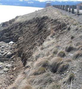
Source: Tom Gore
Verify schedule and adjust as needed.
Sequence activities to reduce the amount and duration of exposed soil.
Limitations
• Seasonal limitations are not always possible to incorporate due to bidding, letting, and administration of contracts. • Work scheduling may be affected by weather. • Other environmental permits or mitigation measures may contain restrictions on scheduling or sequencing of certain work activities.
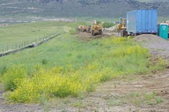
Source: Tom Gore
Effectiveness
• Most effective if the schedule is followed closely and modified/updated as required throughout the construction project. • Least effective when not carefully thought out, when not coordinated with subcontractors, when no guidance to construction staff is provided, or when the schedule/sequencing is not implemented or followed.
Materials
• Not applicable.
Design and Installation
• Develop a project construction schedule, indicating sequencing activities. • Evaluate erosion potential and maximum area that can be exposed at any time.
Consider site-specified criteria such as terrain, soil type, season of work, permit requirements, as well as current and forecasted weather conditions. • Develop a BMP schedule that includes details on the sequencing/implementation and deployment of: - Temporary erosion and soil stabilization BMPs, - temporary run-on and runoff control BMPs, - temporary sediment control BMPs, - snow management BMPs, and - permanent BMPs. • Incorporate good housekeeping and waste management BMPs into the schedule. • Clearly define within the schedule where and when BMPs are to be installed. • Coordinate sequencing and create a timetable for the start and completion of each item, such as site clearing and grubbing, grading, excavation, paving, pouring foundations, and installing utilities to minimize the active construction area during peak storm seasons. • Plan and schedule construction activities to minimize the amount of disturbed land exposed to erosive conditions. • Schedule clearing and grubbing activities to allow existing vegetation to remain in place as long as possible. • Minimize the length of time between bare ground exposure and the installation of soil stabilization and sediment control measures. • Stabilize non-active areas or construction-delayed areas as soon as practical. • Incorporate staged seeding and re-vegetation of graded slopes as work progresses. • Monitor the weather forecast and adjust the construction schedule to allow for the implementation of soil stabilization and sediment controls on all disturbed areas prior to the onset of rain. • Be prepared year round to deploy soil stabilization and sediment control practices.
Erosion may be caused during dry seasons by unseasonable rainfall, wind, and vehicle tracking. Keep the site stabilized year round, and retain and maintain sediment trapping devices in operational condition. • Include dates for significant long-term operations or activities that may have planned non-storm water discharges such as dewatering, saw cutting, grinding, drilling, boring, crushing, blasting, painting, hydro-demolition, mortar mixing, and bridge cleaning. • Sequence utility trenching and excavation activities so that most open portions are closed before new trenching or excavations begin. • Schedule BMP maintenance and inspection per the applicable MPDES/NPDES permit and contract requirements. • Schedule the removal of all temporary BMPs when no longer needed.
Inspection and Maintenance
• Verify that work is progressing in accordance with the schedule. If progress deviates, take corrective actions. • Amend the schedule when changes are warranted.
Removal
• Include anticipated BMP removal information on the schedule. • Anticipate how the viability of removal may be impacted by season of work, construction sequencing, soil type, etc. For example, frozen ground conditions can make removal of temporary BMPs difficult.
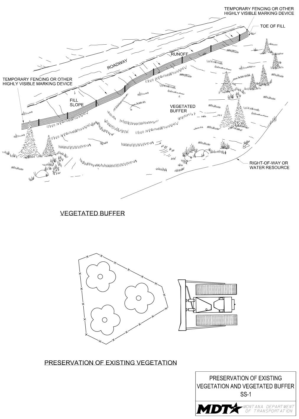
Definition and Purpose
Objectives
The identification and carefully-planned ☐ Construction Site Planning protection of existing natural vegetation (e.g., ☒ Temporary Soil Stabilization trees, shrubs, grasses, and forbs) within the ☒ Run-on and Runoff Control construction area. The purpose of this BMP is ☒ Temporary Sediment Control to minimize the amount of bare soil exposed to ☐ Snow Managementerosive factors; reduce the velocity of storm water runoff; reduce erosion, sediment ☐ Good Housekeeping transport, and tracking; provide an area for ☐ Waste Management runoff to permeate the soil; provide buffers, screens, and aesthetics values; provide biofiltration (capture/process of pollutants); and provide fully-developed habitat for wildlife. It is the most inexpensive form of erosion control.
AT A GLANCE
Applications
☒ Site Perimeter ☐ Inlets and Outlets ☐ Exposed Areas ☐ Sediment Traps/Basins ☒ Slopes ☒ Near Water/Wetlands ☒ Toe of Slopes ☐ Pollution/Material ☐ Ditches Sources ☐ Cut/Fill Transitions

Alternative BMPs to Consider
• Not applicable
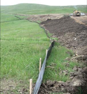
Source: Tom Gore
Mark areas to be preserved with high visibility, temporary fencing.
Vegetated buffer width will depend on site characteristics, right-of-way limits, and slope.
Use In Conjunction With
• CP-1 Scheduling • Secondary soil stabilization BMPs • Secondary run-on and runoff control BMPs • Secondary sediment control BMPs
Limitations
• Vegetated buffer must be within right-of-way. • Protection of existing vegetation requires planning and may limit the area available for construction activities. • Difficult to implement on sites with restricted access. • If vegetative buffer zones are not wide enough, additional erosion and sediment control BMPs may be required when slopes have significant lengths or steepness.
Source: Tom Gore
Effectiveness
• Preserving existing vegetation is the most effective BMP for soil stabilization and erosion control.
Materials
• Highly-visible fencing.
Design and Installation
• Review project plans, as existing vegetation and/or wetland areas may already be designated as ’do not disturb’. • Identify existing vegetation to preserve and vegetative buffers to maintain during project scheduling and sequencing. • Preserve vegetation in clumps, blocks, or buffer strips. • The vegetated buffer width to preserve should be determined after careful consideration of right-of-way limits, equipment access, slope, vegetation, soils, depth to impermeable layers, runoff sediment characteristics, type and quantity of storm water pollutants, and annual rainfall. • The buffer width to preserve should increase as slope increases. • Do not begin clearing and grubbing, grading, and other soil-disturbing construction activities prior to marking and fencing existing vegetation. • Mark all areas to be preserved with highly-visible, temporary fencing to prevent construction traffic and equipment from disturbing designated vegetated areas. • Wherever practicable, install temporary fencing around vegetation so all ground disturbance occurs outside the drip line of preserved trees and shrubs. • Keep all construction equipment, construction materials, parking areas, and waste out of designated fenced areas. • Keep equipment away from trees to prevent trunk and root damage. • Do not allow removed trees to be felled, pushed, or pulled into any retained trees.
Inspection and Maintenance
• Provide regular inspections at the frequency required by the NPDES/MPDES storm water permit. If no storm water permit is required for the project, conduct inspections as specified in the contract. • Ensure all project personnel are aware of areas to be preserved. • Maintain or replace all fencing, as needed, for the duration of the work or until no longer needed. • Ensure that existing vegetation remains healthy and undamaged. • Evaluate the preserve-in-place vegetation for signs of stress and any damage from foot or vehicular traffic and address as necessary. • Remove and replace trees or shrubs if they are damaged seriously enough to affect their survival. • Remove any sediment that has encroached onto the vegetative buffer. Minimize disturbance to vegetation during sediment removal.
Removal
• Remove all temporary fencing and marking devices when no longer needed, or upon completion of the work.
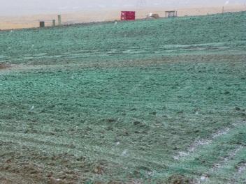
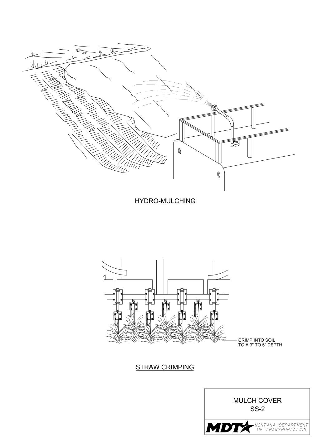
Definition and Purpose
Objectives
Involves the application of a layer of suitable ☐ Construction Site Planning organic material to the soil surface through ☒ Temporary Soil Stabilization mechanical means (drill or studded roller) or ☒ Run-on and Runoff Control hydraulic spraying. Hydraulic applications use ☐ Temporary Sediment Control water and a tackifier to adhere the material to ☐ Snow Managementthe soil surface. Mulching can be used alone to temporarily stabilize areas not ready to be ☐ Good Housekeeping seeded, or as part of the final prepared grade ☐ Waste Management to protect the surface during seed germination. Mulching provides immediate temporary protection of bare soil from raindrop impact or wind erosion. It also enhances plant establishment by conserving moisture and moderating soil temperatures. The roughened surface created through mulching also reduces runoff velocity.
AT A GLANCE
Applications
☐ Site Perimeter ☐ Inlets and Outlets ☒ Exposed Areas ☐ Sediment Traps/Basins ☒ Slopes ☐ Near Water/Wetlands ☒ Toe of Slopes ☐ Pollution/Material ☐ Ditches Sources ☒ Cut/Fill Transitions
Alternative BMPs to Consider
• SS-5 Soil Binders • SS-7 Surface Roughening • SS-6 Rolled Erosion
Control Products
Use In Conjunction With
• CP-1 Scheduling • SS-3 Temporary
Seeding • SS-7 Surface
Roughening • RC-1 Earth Dikes,
Drainage Swales and
Lined Ditches
Limitations
• Surface mulch should not be applied on slopes to be broadcast seeded, because the mulch will prevent soil/seed contact. • Cannot be applied in areas of concentrated flows. • Can be blown or washed away if not adequately crimped or tackified. • Potential for accidental introduction of undesirable weed species.
Source: Tom Gore
Apply hydraulic mulch uniformly on a roughened surface.
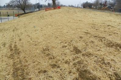
Do not just scatter straw mulch on the exposed surface. Straw must be applied uniformly and secured through crimping or tacking.
Source: Tom Gore
Limitations Straw Mulch
• Availability of straw may be limited due to high demand or time of year. • When straw blowers are used, application areas are typically limited to within 150 feet of equipment. • Crimping or punching of straw does not work as well in sandy soils.
Hydraulic Mulch
• Wood fiber hydraulic mulches are generally short-lived (only last a part of a growing season). • Hydraulic tackifiers need 24 hours to dry to be effective; therefore, they should not be applied immediately prior to a storm event.
Effectiveness
• Most effective when appropriate mulch product is matched to the appropriate slope conditions. • Least effective when applied during rain or wind events and not secured to the soil surface.
Materials Vegetative (Straw) Mulch
• Vegetative mulch is dried cereal grain or oilseed crop straw, cornfield residue, or grass hay with majority of stems and leaves at least 4 inches in length. Ensure straw is certified weed free.
Tackifier and Dyes
• Ensure tackifiers contain either plant-derived hydrocolloid or polymeric materials.
This may include an organic, soluble powder adhesive, a derivative of plant material
Psyllium or Guar.
Hydraulic Mulch
• Wood Fiber. Wood fiber hydraulic mulch is specifically prepared wood fibers free of growth or germination inhibiting materials that forms a homogeneous slurry when combined with water, tackifiers, fertilizer, and other specified additives and remains uniformly suspended under agitation. The mulch may be colored with a water-soluble, non-toxic dye to aide visual metering during application. • Straw Fiber. Straw fiber hydraulic mulch is specially manufactured and prepared straw stems that are packaged and commercially sold specifically as hydraulic mulch. Straw hydraulic mulch can be formulated as 100% straw or combined with other types of mulch and tackifier products during the manufacturing process. • Multi-fiber. Multi-fiber hydraulic mulches are composed of various types and percentages of natural fibers. They can be combined with tackifier products during the manufacturing process.
Design and Installation
• Do not apply mulch to ground having free surface water or if wind prevents uniform distribution. • Do not apply mulch on areas covered with snow.
Vegetative (Straw) Mulch
• Apply straw mulch under low wind conditions. • Evenly distribute straw mulch at a minimum rate of 4000 lbs/acre. • Apply straw mulch with a mulch spreader/straw blower. • Secure straw mulch to the slopes with a non-asphalt based tackifier containing either plant derived hydrocolloid or polymeric materials. Select tackifier based on longevity and ability to hold the fibers in place. • If a tackifier is used, do not apply during or immediately before rainfall. • For slopes 3:1 or flatter, tuck (punch or crimp) straw mulch into the soil to a 3- to 5inch depth with notched disk blades. • If temporary erosion controls are needed, straw tucking followed by seeding within the seeding season are acceptable measures.
Hydraulic Mulch
• Prior to application, roughen slope areas (refer to SS-7 Surface Roughening). • Apply hydraulic mulch a minimum of 24 hours prior to a storm event to allow for adequate drying. • Apply the mulch to produce a uniform mat-like cover. • Start mulching at the top of the slope and work downward. Use extension hoses to reach the slope extremities. • Apply in accordance with submitted manufacturer's recommended application rates and methods for mulch and stabilizing emulsion to achieve complete coverage of target area. General application rates are as follows:
Product Material Minimum Application Rate
Wood-based hydraulic mulch Wood 2000 Lbs./Acre
Inspection and Maintenance
• Provide regular inspections at the frequency required by the NPDES/MPDES storm water permit to ensure mulch cover is maintained and functions properly. If no storm water permit is required for the project, conduct inspections as specified in the contract. • Maintain unbroken, temporary mulched ground cover throughout the period of construction when soils are not being reworked.
Removal
• Not applicable.
Definition and Purpose
Objectives
Temporary seeding is the establishment of a ☐ Construction Site Planning temporary vegetative cover on disturbed areas ☒ Temporary Soil Stabilization with a slope of 3:1 or flatter that will be ☒ Run-on and Runoff Control exposed for longer than 14 days and that will ☒ Temporary Sediment Control undergo further disturbance. Temporary ☐ Snow Managementseeding is not the same as erosion seeding. Once established, temporary seeding also ☐ Good Housekeeping reduces flow velocity, traps sediments, ☐ Waste Management promotes infiltration, and improves the appearance of the site.
AT A GLANCE
Applications
☐ Site Perimeter ☐ Inlets and Outlets ☒ Exposed Areas ☒ Sediment Traps/Basins ☒ Slopes ☒ Near Water/Wetlands ☒ Toe of Slopes ☐ Pollution/Material ☒ Ditches Sources ☐ Cut/Fill Transitions
Alternative BMPs to Consider
• SS-2 Mulch Cover • SS-6 Rolled Erosion • SS-5 Soil Binders Control Products • SS-7 Surface Roughening
Use In Conjunction With
• CP-1 Scheduling • SS-2 Mulch Cover • SS-7 Slope
Roughening • SC-6 Fiber Rolls • SC-7 Compost Socks
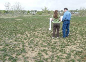
Source: Tom Gore
Temporary seeding should provide adequate cover to prevent erosion and reduce sediment loss.
Limitations
• Rock slopes that cannot be excavated by ripping are not temporarily seeded. • May not be appropriate in dry areas or periods without supplemental irrigation. • Requires time for seed to establish; no immediate results. • Areas impacted by construction traffic will not have successful vegetative growth. • Temporary seeding should only be utilized when there is sufficient time and conditions are favorable for the vegetation to become established. • Steep slopes are not to be seeded with the temporary seeding mix. • It Can compete with permanent seeding/re-vegetation efforts. • Use erosion seeding instead of temporary seeding when slopes are steeper than 3:1.
Effectiveness
• Most effective when drill seeded during those seasons most conducive to growth. • Least effective when seeding occurs on smooth, compacted surfaces.
Materials
• Temporary seeding utilizes cereal barley.
Design and Installation
• Drill seed slopes of 3:1 or flatter. Refer to SS-4 Erosion Seeding for slopes steeper than 3:1. • Provide temporary seeding in accordance with the following recommendations:
April 1— June 30 Cereal Barley —12.0 lbs/acre July 1 — August 31 Temporary Seeding Not Recommended Sept. 1— Nov. 1 Cereal Barley —12.0 lbs/acre*
* Do not temporary seed in this timeframe if the area is to be permanently seeded that fall.
Inspection and Maintenance
• Provide regular inspections at the frequency required by the NPDES/MPDES storm water permit. If no storm water permit is required for the project, conduct inspections as specified in the contract. • Consider an alternate soil stabilization method if temporary seeding does not provide adequate cover and/or is found to be ineffective.
Removal
• Temporary seeding is removed when the area undergoes further disturbance.
Definition and Purpose
Objectives
Well-established vegetative cover is one of the ☐ Construction Site Planning best erosion control measures available. ☒ Temporary Soil Stabilization Erosion seeding is the immediate seeding of ☒ Run-on and Runoff Control freshly exposed slopes. Erosion seeding is not ☒ Temporary Sediment Control the same as temporary seeding. It is used ☐ Snow Managementstrictly on cut and fill slopes steeper than 3:1 that will not undergo further disturbance. The ☐ Good Housekeeping intent of erosion seeding is to apply seed to the ☐ Waste Management soil surface at a time when the surface is rough and receptive to seed coverage. Once established, erosion seeding reduces erosion and flow velocity, traps sediment, promotes infiltration, and improves the appearance of the site.
AT A GLANCE
Applications
☐ Site Perimeter ☐ Inlets and Outlets ☒ Exposed Areas ☐ Sediment Traps/Basins ☒ Slopes ☒ Near Water/Wetlands ☐ Toe of Slopes ☐ Pollution/Material ☐ Ditches Sources ☒ Cut/Fill Transitions
Alternative BMPs to Consider
• SS-2 Mulch Cover • SS-5 Soil Binders • SS-6 Rolled Erosion Control Products
Use In Conjunction With
• CP-1 Scheduling • SS-7 Slope Roughening • SC-6 Fiber Rolls • SC-7 Compost Socks • RC-1 Earth Dikes,
Drainage Swales and
Lined Ditches
Limitations
• Rock slopes that cannot be excavated by ripping are not seeded. • Requires time for seeds to establish; no immediate results. • Erosion seeding does not replace final seeding specified in the contract.
Source: Tom Gore
Apply seeding uniformly to exposed slopes by manual broadcasting.
Effectiveness
• Most effective when the seed is broadcast on a newly roughened surface. • Not effective when seeding occurs on smooth, compacted surfaces.
Materials
• Erosion seeding utilizes Cereal barley, Pryor slender wheatgrass, and/or MT origin
Canada wildrye.
Design and Installation
• Excessively rocky slopes that cannot be excavated by ripping are exempt from erosion seeding. • Conduct erosion seeding on freshly exposed slopes steeper than 3:1 that will not be top soiled or re-disturbed. • Prepare the seedbed by roughening the slopes with furrows trending along the contours. • Accomplish erosion seeding by manual broadcasting with a shoulder-harnessed spreader seeder or its equivalent. • Do not apply during windy conditions. • Use the following mixture and rates of PLS for manual broadcast.
Species
Cereal barley Pryor slender wheatgrass MT origin Canada wildrye Lodorm green needlegrass 10.0 5.0 10.0 5.0
• Erosion seeding does not replace or serve as a substitute for final seeding activities specified in the contract.
Inspection and Maintenance
• Provide regular inspections at the frequency required by the NPDES/MPDES storm water permit. If no storm water permit is required for the project, conduct inspections as specified in the contract. • Consider an alternate soil stabilization method if erosion seeding does not provide adequate cover and/or is found to be ineffective.
Lbs PLS per acre
Removal
• Not applicable.
Definition and Purpose
The application and maintenance of a soil stabilizer to exposed soil surfaces. Soil binders are applied to the soil surface to temporarily prevent water-induced erosion of exposed soils on construction sites. Soil binders also provide temporary dust, wind, and soil stabilization (erosion control) benefits.
AT A GLANCE
Objectives
☐ Construction Site Planning ☒ Temporary Soil Stabilization ☐ Run-on and Runoff Control ☐ Temporary Sediment Control ☐ Snow Management ☐ Good Housekeeping ☐ Waste Management
Applications
☐ Site Perimeter ☐ Inlets and Outlets ☒ Exposed Areas ☐ Sediment Traps/Basins ☒ Slopes ☐ Near Water/Wetlands ☐ Toe of Slopes ☒ Pollution/Material ☐ Ditches Sources ☒ Cut/Fill Transitions
Alternative BMPs to Consider
• SS-2 Mulch Cover • SS-6 Rolled Erosion Control Products
Source: Tom Gore
Soil binders can provide temporary dust, wind, and soil stabilization benefits.
Use In Conjunction With
• CP-1 Scheduling • SS-1 Preservation of
Existing Vegetation/
Vegetative Buffers • SS-3 Temporary
Seeding • SS-4 Erosion Seeding • SS-7 Surface Roughening • SC-6 Fiber Rolls • SC-7 Compost Socks
Limitations
• Soil binders are temporary in nature and may need reapplication, especially after a storm event. • Soil binders require a minimum curing time until fully effective, which may be 24 hours or longer. • Soil binders will generally experience spot failures during heavy rainfall events. Soil binders do not hold up well to pedestrian or vehicular traffic.
Effectiveness
• Most effective when applied during dry, still conditions. • Least effective when applied to areas primarily made up of silt and clay.
Materials Selecting a Soil Binder
• Consider where the soil binder will be applied, if it needs a high resistance to leaching or abrasion, and whether it needs to be compatible with any existing vegetation. Determine the length of time soil stabilization will be needed, and if the soil binder will be placed in an area where it will degrade rapidly. • Soil binders are generally appropriate as follows. 1. Copolymer: Appropriate for long-term soil stabilization in areas where crosstraffic might occur, or where stabilization needs to be achieved in conjunction with preserving existing vegetation. Longevity can be up to 2 years. It has a high resistance to abrasion and is compatible with existing vegetation. However, it is also relatively costly which makes it less desirable for shortterm or frequent applications. 2. Lignin sulfonate: A byproduct of the kraft paper-making process, it is a natural adhesive that holds plant fibers together. Appropriate for short- or mediumterm soil stabilization applications in low traffic areas. The moderate relative cost makes it less desirable to reapply frequently, though it typically lasts longer than psyllium or guar. With only moderate penetration and a low resistance to abrasion, it would be more suited to areas which will not be disturbed frequently by construction activities. Lignin sulfonate can have an unpleasant odor when applied. 3. Psyllium/Guar: Guar is a non-toxic, biodegradable, natural galactomannanbased hydrocolloid. Psyllium is composed of the finely ground muciloid coating of plantago seeds that is applied as a dry powder or in a wet slurry to the surface of the soil. Appropriate for typical soil stabilizing situations or short-term applications. Because of the relatively low cost, they can be applied more frequently. Longevity is up to 6 months. Their high penetration provides good stabilization, but their moderate resistance to abrasion limits their longevity. They are not very compatible with vegetation.
Design and Installation General Considerations
• Site-specific soil types will dictate which soil binders are appropriate for use.
Applying Soil Binders
• After selecting an appropriate soil binder, the untreated soil surface must be prepared before application. The untreated soil surface must contain sufficient moisture to assist the agent in achieving uniform distribution. Apply in accordance with submitted manufacturer’s recommendations for application rates and methods. • Do not apply soil binders to frozen soil, areas with standing water, or under freezing or raining conditions.
Inspection and Maintenance
• Provide regular inspections at the frequency required by the NPDES/MPDES storm water permit. If no storm water permit is required for the project, conduct inspections as specified in the contract.
Inspection and Maintenance
• Reapply the selected soil binder if needed for proper maintenance and after repairing erosion, if present. • Reapply if surface area has been disturbed.
Removal
• Not applicable.
Definition and Purpose
Objectives
Involves the placement of erosion control ☐ Construction Site Planning blankets and mats, plastic covers, and ☒ Temporary Soil Stabilization geotextiles that are used to temporarily ☒ Run-on and Runoff Control stabilize disturbed soil areas and protect soils ☐ Temporary Sediment Control from erosion by wind or water. Rolled erosion ☐ Snow Managementcontrol products are used when disturbed soils may be particularly difficult to stabilize. They ☐ Good Housekeeping reduce rainfall impact and improve infiltration; ☐ Waste Management provide a microclimate to promote seed establishment; reduce erosion caused by concentrated flows; and hold mulch, seed, fertilizer, and topsoil in place.
AT A GLANCE
Applications
☐ Site Perimeter ☒ Inlets and Outlets ☒ Exposed Areas ☒ Sediment Traps/Basins ☒ Slopes ☒ Near Water/Wetlands ☒ Toe of Slopes ☒ Pollution/Material ☒ Ditches Sources ☒ Cut/Fill Transitions
Alternative BMPs to Consider
• SS-1 Preservation of • SS-4 Erosion Seeding
Existing Vegetation/ • SS-5 Soil Binders
Vegetative Buffers • SS-7 Surface Roughening • SS-2 Mulch Cover
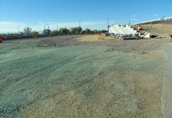
Source: MDT
Install erosion control blankets running in the direction of flow and adequately secure down.
Properly anchor erosion control blankets to the ground using anchor trenches to prevent blanket pullout and undermining.
Use In Conjunction With
• CP-1 Scheduling • RC-1 Earth
Dike/Drainage
Swales/Lined Ditches • RC-2 Outlet Velocity
Dissipation Devices • RC-3 Temporary Slope
Drains • SC-1 Silt Fence • SC-3 Sediment Trap • SC-6 Fiber Rolls • SC-7 Compost Socks
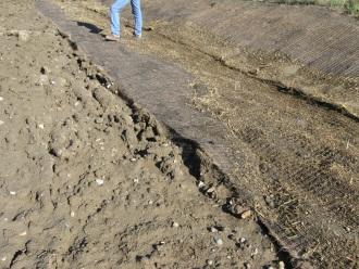
Source: MDT
Limitations
• More expensive than other erosion control measures, due to labor and material costs. • Some products have the potential to trap wildlife. • Not suitable on slopes where vegetation is present and already established. • Are generally not suitable for excessively rocky sites. • Non-degradable fabrics must generally be removed when permanent stabilization measures are ready to be installed. • Must be properly anchored; some geotextiles may increase runoff or blow away. • Plastic covers are limited to covering stockpiles or very small graded areas for short periods of time. • Plastic sheeting is easily vandalized or torn and is susceptible to photodegradation and must be disposed of properly.
Limitations
• The use of plastic sheeting provides an impermeable surface which can increase runoff and risk of erosion problems in the areas subject to increased flow.
Effectiveness
• Most effective when proper fabric is selected for the site conditions and the product is installed correctly. • Least effective when the rolled erosion control product does not have complete contact with the soil and is not properly anchored to the ground.
Materials Material Selection
• There are many types of erosion control blankets and mats, plastic covers, and permanent erosion control geotextiles. Selection of the appropriate product should be based on the specific type of application and site conditions.
Plastic Covers
• Provide plastic cover material used for temporary soil stabilization consisting of polyethylene sheeting. A minimum thickness of 6 mil is recommended.
Erosion Control Blankets/Mats
• Designed to stabilize and hold previously-applied mulch or compost on slopes as well as to stabilize newly constructed channels, ditches, stream banks and slopes. • Natural fiber netting is available in various fiber types, strengths, weights and mesh-opening sizes and are described in the contract.
Geotextiles
Permeable woven and non-woven, permeable polymeric fabric. There are a wide variety of geotextiles available.
Design and Installation General
• Proper selection, design, and installation of the appropriate rolled erosion control product are critical to its effectiveness. • Proper site preparation is essential for complete contact of the blanket or matting with the soil. • Remove all rocks, clods, vegetation, or other obstructions so that the installed blankets or mats will have complete, direct contact with the soil. • Must be properly anchored to reduce the potential for undermining.
Geotextiles
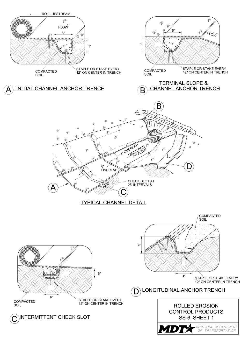
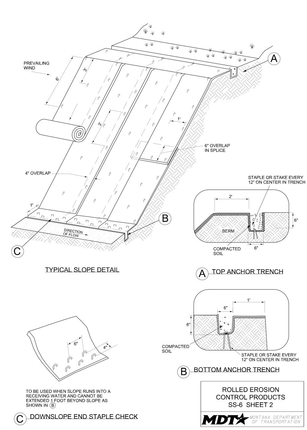
• Install in accordance with the requirements shown on drawing SS-6 unless
Contractor submits alternate manufacturer specifications to MDT.
Design and Installation Plastic Covers
• Limit the use of plastic to covering stockpiles, or very small graded areas for short periods of time (such as through one damaging storm event), until alternative measures, such as seeding and mulching, are installed. • Anchor plastic covers using sandbags or other materials capable of preventing infiltration of surface waters under the plastic. Provide overlap of all seams and either tape all seams, or weight down entire length of seam.
Erosion Control Blankets/Mats
• Install in accordance with the requirements shown on drawing SS-6 unless
Contractor submits alternative manufacturer specifications to MDT. • Seed the area before eroson control blanket installation. All trenches and other areas disturbed during installation of the blanket or mat must be re-seeded. • For slopes, unroll the blanket vertically downslope. Overlap end of blanket 6 inches over downslope blanket. Overlap blanket 4 inches over the adjacent blanket. • For channels and ditches, unroll the blanket parallel to the channel or ditch. Overlap end of blanket 6 inches over downstream blanket. Overlap blanket 4 inches over adjacent blanket.
Inspection and Maintenance
• Provide regular inspections at the frequency required by the NPDES/MPDES storm water permit to ensure rolled erosion control products are functioning properly. If no storm water permit is required for the project, conduct inspections as specified in the contract. • Inspect and maintain all areas treated with temporary geotextiles, mats, blankets, and other covers to provide adequate erosion control. • Inspect for cracks, tears, pullout, sagging, or undermining. • Maintain contact between rolled erosion product and the ground at all times. • Maintain all slopes to prevent erosion.
Removal
• Remove non-degradable temporary fabrics from the site when no longer needed or at the completion of the work, and dispose of them in accordance with all laws, rules, and applicable regulations.
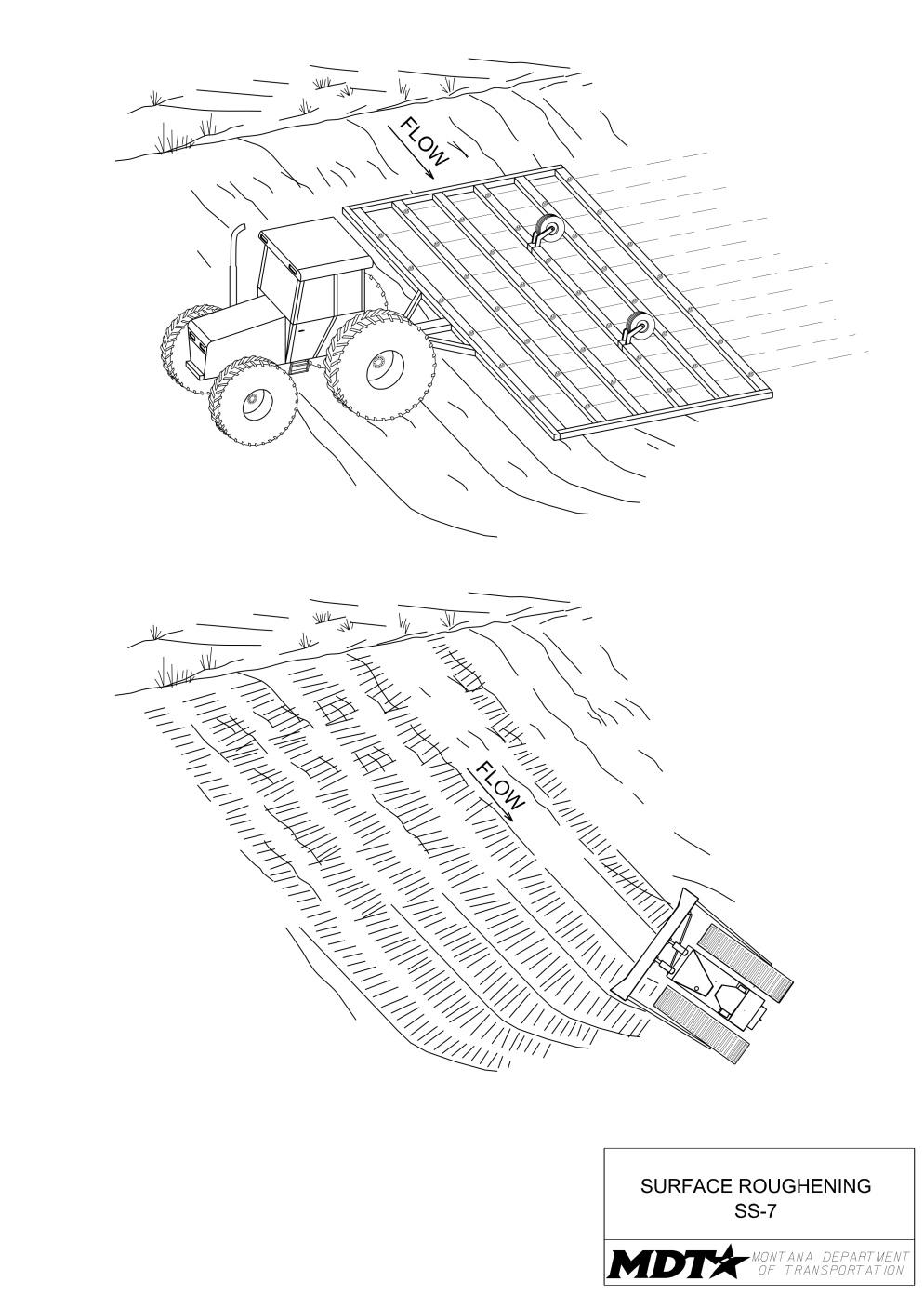
Definition and Purpose
A temporary erosion control practice often used in conjunction with grading. It involves increasing the roughness of a bare soil surface using construction equipment. A rough soil surface allows surface ponding and slows storm water runoff and velocities. Surface roughening increases infiltration, reduces erosion, and traps sediment.
AT A GLANCE
Objectives
☐ Construction Site Planning ☒ Temporary Soil Stabilization ☒ Run-on and Runoff Control ☒ Temporary Sediment Control ☐ Snow Management ☐ Good Housekeeping ☐ Waste Management
Applications
☐ Site Perimeter ☐ Inlets and Outlets ☒ Exposed Areas ☐ Sediment Traps/Basins ☒ Slopes ☐ Near Water/Wetlands ☒ Toe of Slopes ☒ Pollution/Material ☐ Ditches Sources ☒ Cut/Fill Transitions
Alternative BMPs to Consider
• SC-6 Fiber Rolls • SC-7 Compost Socks
Use In Conjunction With
• CP-1 Scheduling • SS-2 Mulch Cover • SS-3 Temporary Seeding • SS-4 Erosion Seeding
Limitations
• Surface roughening may not be practical for very sandy or rocky slopes. • Surface compaction might occur when roughening with wheeled machinery. • If roughening is adversely impacted by a heavy storm, the surface will need to be re-roughened.
Source: MDT
Use machinery to create a series of ridges and depressions that run horizontal across the slope and parallel to the contour.
Do not create ridges vertical down the slope. This facilitates channeling and erosion.
Source: Tom Gore
Effectiveness
• Most effective when installed across the horizontal plane of the slope (parallel to slope contour). • Least effective in very sandy or rocky soils.
Materials
• Not applicable.
Design and Installation
• Surface roughening can be applied to large soil stockpiles, gradual/flatter slopes and to steeper slopes. However, all slopes steeper than 3:1 and greater than 5 vertical feet require surface roughening, excluding rock slopes that cannot be excavated by ripping. • To slow erosion, complete surface roughening as soon as possible after the vegetation has been removed. • Surface roughening should be used in conjunction with erosion seeding. • Roughening methods include disking, chisel plowing, grooving and tracking. Factors to consider when choosing an appropriate method include slope steepness, whether the slope is formed by cutting or filling, and available equipment. • The use of rakes and hand tools is not an acceptable or allowed method for providing surface roughening. • The following methods may be used for surface roughening. - Grooving. This technique uses machinery to create a series of ridges and depressions that run horizontal across the slope parallel to the contour. Grooves should be made using an appropriate implement that can be safely operated on the slope, such as disks, tillers, spring harrows, or the teeth on a motor patrol or bulldozer. The surface roughness should resemble a freshly plowed field. - Tracked. Tracked machinery should be operated perpendicular to the slope to leave horizontal depressions in the soil. Tracking is generally not as effective as other roughening methods.
Inspection and Maintenance
• Provide regular inspections at the frequency required by the NPDES/MPDES storm water permit to ensure roughened slopes are functioning properly. If no storm water permit is required for the project, conduct inspections as specified in the contract. • Inspect roughened areas after storms for erosion and failure. • Regular inspection of roughened slopes will indicate where additional erosion and sediment control measures are needed. • If erosion occurs, fill, regrade, and/or reseed (if applicable) the eroded area immediately. • Maintain all slopes to prevent erosion and reduce sediment loss.
Removal
• Not applicable.
Definition and Purpose
Consists of applying water, soil binders, or installing wind barriers or protective covers as necessary to prevent soil erosion. Several soil stabilization BMPs can be applied for wind erosion control.
AT A GLANCE
Objectives
☐ Construction Site Planning ☒ Temporary Soil Stabilization ☐ Run-on and Runoff Control ☐ Temporary Sediment Control ☐ Snow Management ☐ Good Housekeeping ☐ Waste Management
Applications
☒ Site Perimeter ☐ Inlets and Outlets ☒ Exposed Areas ☐ Sediment Traps/Basins ☒ Slopes ☐ Near Water/Wetlands ☐ Toe of Slopes ☒ Pollution/Material ☐ Ditches Sources ☐ Cut/Fill Transitions
Alternative BMPs to Consider
• Not applicable.
Use In Conjunction With
• CP-1 Scheduling • SS-2 Mulch Cover • SS-3 Temporary Seeding • SS-4 Erosion Seeding • SS-5 Soil Binders • SS-6 Rolled Erosion Control Products
Limitations
• Effectiveness depends on soil, temperature, humidity, wind velocity, and wind direction.
Source: Tom Gore
Dust should be suppressed through the application of water or soil binders.
Effectiveness
• Most effective when appropriate BMPs are selected based on site conditions like soil, temperature, humidity, wind velocity, and wind direction.
Materials
• Refer to SS-5 Soil Binders, SS-6 Rolled Erosion Control Products, and any other applicable BMPs for specified materials. • Wind fencing consists of a prefabricated commercial product made of woven polyethylene and ultraviolet resistant material with a porosity of 50% minimum.
Design and Installation Water Spraying
• Apply water using pressure-type distributors or pipelines equipped with a spray system or hoses and nozzles capable of uniformly distributing the water over the application area. • Do not use excessive amounts of water that may cause soils to be saturated and create other problems such as excess runoff, mud/dirt tracking, or icing in winter months. • Unless water is applied by means of pipelines, make at least one mobile unit available at all times to apply water or dust suppressants. • If reclaimed wastewater is used, comply with DEQ water reclamation criteria for sources and discharges. Do not convey non-potable water in tanks or drain pipes that may be used to convey potable water. Do not connect between potable and non-potable water supplies. Mark non-potable tanks, pipes, and other conveyances as “Non-Potable Water – Do Not Drink.”
Dust Suppressants
• Apply in accordance with submitted manufacturer’s recommended application rates and methods for soil stabilizers and soil binders. • Apply materials in accordance with all local, state, tribal, and federal regulations.
Wind Barriers
• Provide wind fencing consisting of a prefabricated commercial product made of woven polyethylene and ultraviolet resistant material with a minimum porosity of 50%. • Wind fencing is most protective when installed in an orientation perpendicular to the prevailing wind direction. • Wind fencing should be a minimum height of 45 inches, with the bottom gap between the fencing and the ground at 15 inches minimum. • For wind protection of stockpiles, place wind fencing upwind of the stockpile a distance of approximately 3 times the height of the stockpile.
Covers
• Refer to SS-6, Rolled Erosion Control Products for installation guidelines for slopes and stockpiles.
Inspection and Maintenance
• Provide regular inspections at the frequency required by the NPDES/MPDES storm water permit to ensure BMPs installed for wind erosion are functioning properly. If no storm water permit is required for the project, conduct inspections as specified in the contract. • Check areas protected to ensure coverage. • Continue to disperse water as needed for dust suppression.
Removal
• Remove wind fencing and other non-degradable devices used for wind erosion control when soils are stabilized or upon completion of the work.
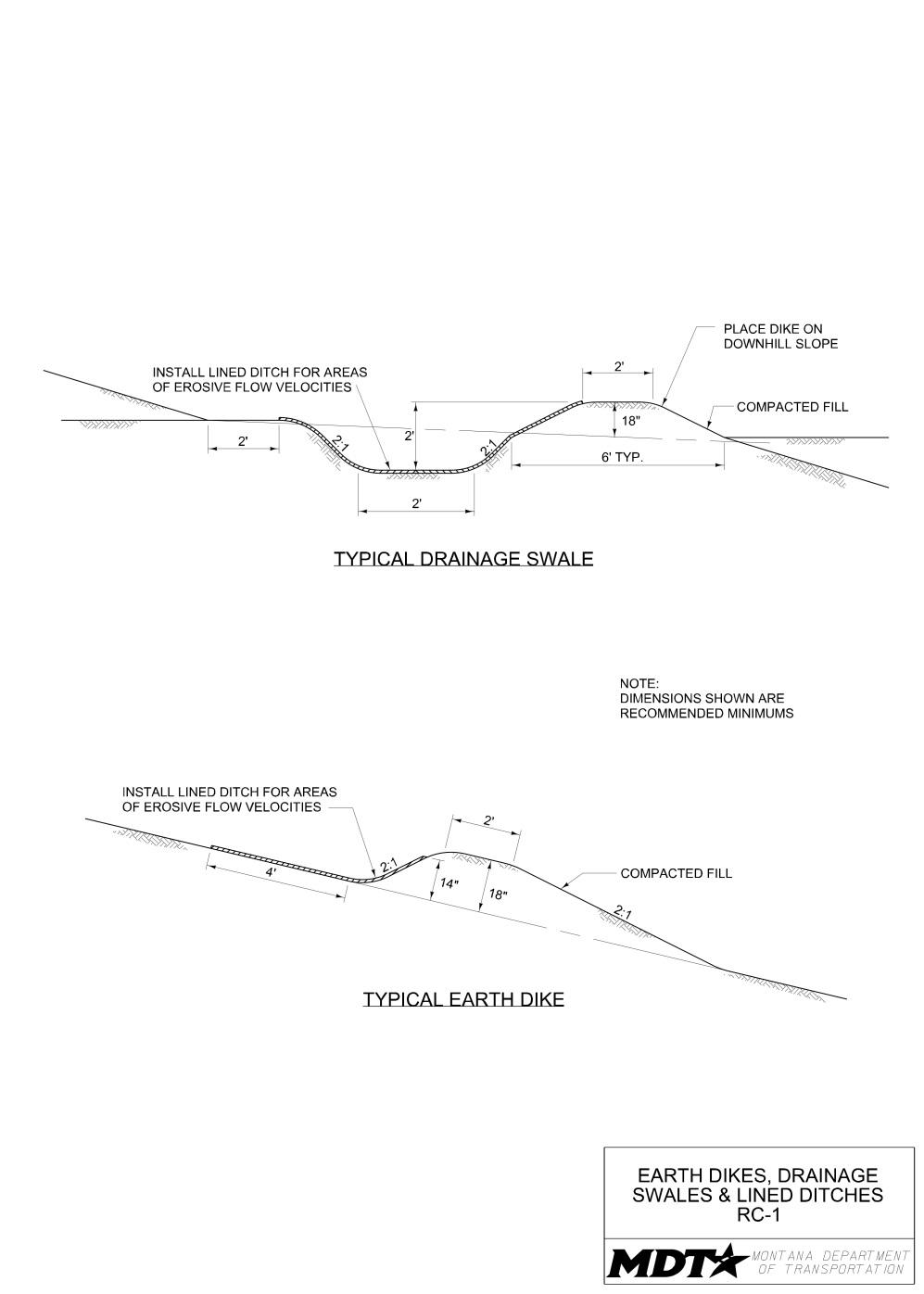
RC-1 Earth Dikes/Drainage Swales/Lined Ditches
Definition and Purpose
Structures and grading techniques that intercept, divert, and convey surface run-on and runoff, generally sheet flow, to a desired location to prevent erosion.
Objectives
☐ Construction Site Planning ☒ Temporary Soil Stabilization ☒ Run-on and Runoff Control ☒ Temporary Sediment Control ☐ Snow Management ☐ Good Housekeeping ☐ Waste Management
AT A GLANCE
Applications
☒ Site Perimeter ☒ Inlets and Outlets ☐ Exposed Areas ☒ Sediment Traps/Basins ☒ Slopes ☐ Near Water/Wetlands ☒ Toe of Slopes ☒ Pollution/Material ☒ Ditches Sources ☐ Cut/Fill Transitions
Source: Tom Gore
Alternative BMPs to Consider
• RC-3 Slope Drains
Use In Conjunction With
• CP-1 Scheduling • SS-3 Temporary
Seeding • SS-6 Rolled Erosion
Control Blankets • RC-2 Outlet Velocity
Dissipation Devices • RC-3 Slope Drains • SC-2 Desilting Basin • SC-3 Sediment Trap • SC-4 Check Dams • SC-5 Dugout Ditch
Basin
Limitations
• Run-on and runoff must be diverted into existing or
Dikes and ditches can be used at toe of slope to divert and convey storm water. Diversions should not include loose fill.
Use compacted dikes to intercept and divert storm water.
Source: Tom Gore
stabilized drainages or desilting basins or sediment traps. • High runoff velocities may scour and erode dikes and swales. It may be necessary to combine with other soil stabilization and sediment control BMPs such as SS-6 Rolled
Erosion Control Products, or SC-4 Check Dams. • Earth dikes/drainage swales and lined ditches are not suitable as sediment trapping devices.
Effectiveness
• Most effective when ditches, swales, and dikes are correctly sized for expected flows and located where run-on and runoff can be adequately intercepted. • Least effective when swales and ditches do not have positive drainage. Ditches and swales without positive drainage are easily bypassed, overwhelmed, or filled in with sediment.
Materials
• Construct dikes and drainage swales using compacted soil. • Utilize rolled erosion control products or other appropriate stabilization measures (e.g. outlet velocity dissipation devices, slope drains, and desilting basins) in conjunction with lined ditches.
Design and Installation
• Earth dikes, drainage swales and lined ditches can be constructed at the top and bottom of slopes, constructed to convey flows from an undisturbed area into a stabilized area or sediment trap, and constructed to convey run-on and runoff around stockpiles and other storage areas. • For unlined ditches and swales, provide a gradual positive drainage grade, as excessively steep grades are subject to erosion and gully formation. • Construct diversion ditches and swales with rounded or flat bottoms to avoid concentrating flows at the bottom of the channel, which could lead to ditch erosion. • Do not construct diversion ditches and swales using loose or uncompacted fill. • Provide a lined ditch for high flow velocities, following the guidelines for SS-6 Rolled
Erosion Control Products and/or RC-3 Slope Drains. • A minimum height of 18 inches is recommended for earthen dikes. • Compact earthen material used in dikes. • Do not divert runoff from the project site onto adjacent property. • When possible, install and utilize dikes, swales, and ditches early in the construction process. • Provide stabilized outlets to divert sediment-laden flow into sediment traps.
Inspection and Maintenance
• Provide regular inspections at the frequency required by the NPDES/MPDES storm water permit to ensure dikes, drainage swales, and ditches are maintained and function properly. If no storm water permit is required for the project, conduct inspections as specified in the contract. • Inspect channel linings, embankments, and beds of ditches and berms for washout/erosion. Repair or replace as needed to remedy observed deficiencies. • Inspect beds of ditches for debris and sediment accumulation and remove.
Incorporate removed sediment into the project or dispose of it in accordance with all laws, rules, and applicable regulations.
Removal
• Completely remove temporary dikes, ditches, and swales as soon as the surrounding drainage area has been stabilized, or upon completion of the work.
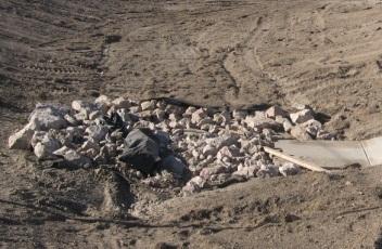
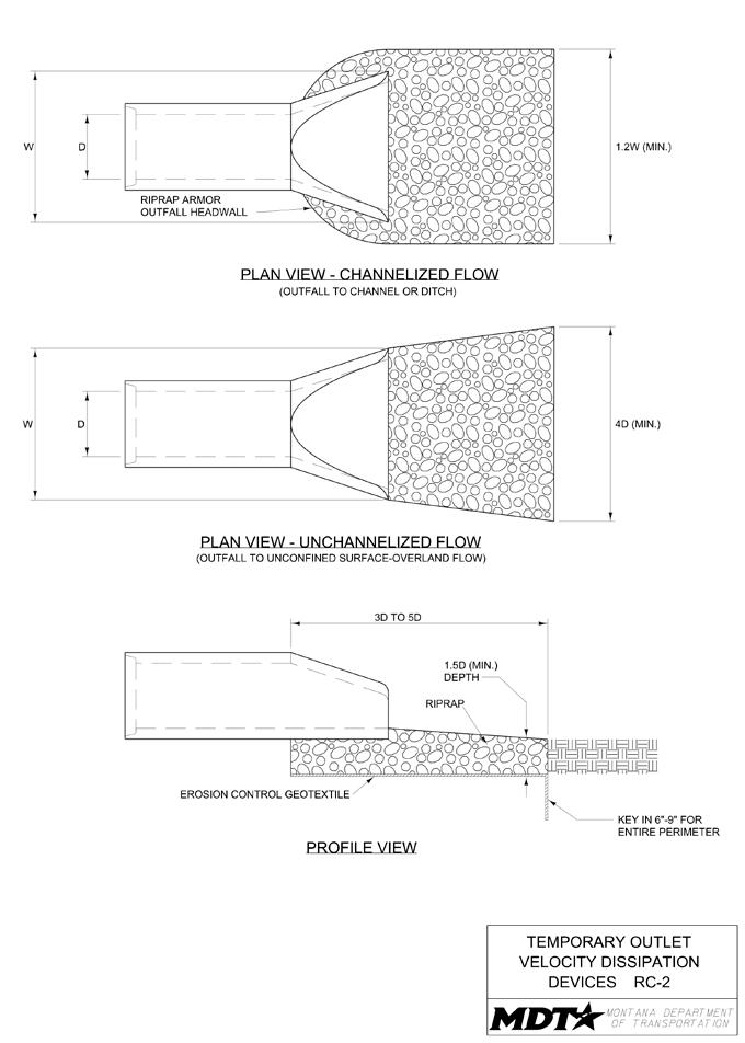
Definition and Purpose
Temporary devices placed at conveyance outlets to prevent scour and reduce the velocity and/or energy of storm water flows and discharges. The devices described here are temporary and are not to be confused with permanent outlet protection and velocity dissipation devices that may be included in the contract.
Objectives
☐ Construction Site Planning ☒ Temporary Soil Stabilization ☒ Run-on and Runoff Control ☒ Temporary Sediment Control ☐ Snow Management ☐ Good Housekeeping ☐ Waste Management
AT A GLANCE
Applications
☐ Site Perimeter ☒ Inlets and Outlets ☐ Exposed Areas ☒ Sediment Traps/Basins ☐ Slopes ☒ Near Water/Wetlands ☐ Toe of Slopes ☐ Pollution/Material ☒ Ditches Sources ☐ Cut/Fill Transitions
Alternative BMPs to Consider
• SC-10 Gravel Bag Berm
Use In Conjunction With
• CP-1 Scheduling • SS-6 Rolled Erosion Control Products • RC-1 Earth Dikes/Drainage Swales/Lined Ditches • RC-3 Temporary Slope Drains • SC-2 Desilting Basin • SC-3 Sediment Trap • SC-6 Fiber Rolls • SC-7 Compost Socks
Limitations
• Loose rock may be washed away during high flows. • Can increase erosion if installed improperly.
Source: MDT
Size dissipation devices appropriately. Maintain to prevent pullout of underlying fabric.
Install temporary velocity dissipation devices to prevent erosion at outlets
Source: Tom Gore
Effectiveness
• Most effective when sized properly based on expected flow volumes and velocities. • Least effective when the dissipation device is not embedded below the ground surface and does not include a geotextile fabric underlayment.
Materials
• There are many types of energy dissipaters, with rock represented in the RC-2 drawing. • Type 1 or Type 2 rock bank protection (18- to 24-inch nominal thickness). • Erosion control geotextile.
Design and Installation
• Temporary outlet velocity dissipation devices may be placed at the outlets of pipes, drains, culverts, slope drains, diversion ditches, swales, sediment traps, desilting basins, conduits or channels. • Place Type 1 or Type 2 rock bank protection (18- to 24-inch nominal thickness) at outlet. • Before the rock is installed, place an erosion control geotextile at the outlet between the underlying soil and the rock. Install in accordance with the requirements shown on drawing SS-6 unless Contractor submits alternative manufacturer specifications to MDT. • Carefully place rock to avoid punching, cutting, tearing, or damaging the geotextile fabric. • Embed rock 6 to 9 inches below the ground surface for the entire perimeter. • If velocity dissipater will be constructed as an apron: - Align apron with receiving stream such that a straight line is created. If a curve is needed to fit site conditions, place it in upper section of apron. - Follow guidelines on the RC-2 drawing for sizing. - If size of apron is large, protect underlying filter fabric with a gravel blanket. - Provide additional protection for outlets on slopes steeper than 10%.
Inspection and Maintenance
• Provide regular inspections at the frequency required by the NPDES/MPDES storm water permit to ensure dissipation devices are functioning properly. If no storm water permit is required for the project, conduct inspections as specified in the contract. • Inspect temporary measures prior to anticipated storm events, and as soon as possible after storm events. • Inspect after high flows, for displacement of dissipation devices and/or damage to the underlying fabric and repair as needed. • Inspect for scour beneath and around the dissipation devices and around the outlet. • Replace rock and repair damage to dissipation devices, to slopes, or underlying filter fabric immediately. • Consider adding additional rock/protection if scour is occurring downstream of dissipation device.
Removal
• Completely remove temporary dissipation devices as soon as the surrounding drainage area has been stabilized, or upon completion of the work.
Definition and Purpose
Objectives
A temporary pipe or lined chute used to ☐ Construction Site Planning intercept run-on/runoff and carry those ☒ Temporary Soil Stabilization concentrated flows from the top of a slope and ☒ Run-on and Runoff Control into a stabilized ditch or channel, sediment ☐ Temporary Sediment Control trapping device, or large stabilized area at the ☐ Snow Managementtoe of the slope. Slope drains are often used with dikes and lined ditches to intercept and ☐ Good Housekeeping direct surface flow. Their primary purpose is to ☐ Waste Management prevent run-on/runoff from flowing over slopes that are at high risk of erosion or slope failure.
AT A GLANCE
Applications
☐ Site Perimeter ☐ Inlets and Outlets ☐ Exposed Areas ☐ Sediment Traps/Basins ☒ Slopes ☒ Near Water/Wetlands ☐ Toe of Slopes ☐ Pollution/Material ☒ Ditches Sources ☒ Cut/Fill Transitions
Alternative BMPs to Consider
• RC-1 Earth Dikes/ Drainage Swales/ Lined Ditches
Use In Conjunction With
• CP-1 Scheduling • RC-1 Earth Dikes/
Drainage Swales/
Lined Ditches • RC-2 Outlet Velocity Dissipation Devices • SC-2 Desilting Basin • SC-3 Sediment Trap
Limitations
• Volume of surface flow to be conveyed must not exceed capacity of structure. • The area to be drained through a temporary slope drain should not exceed 10 acres. • May become clogged or overcharge during large storms forcing water around the pipe or lined channel. • Severe erosion may result when slope drains fail by over topping or pipe separation.
Source: Tom Gore
Properly-installed slope drains are designed for the drainage area, anchored to the slope, and include outlet velocity dissipation devices.
Inspect slope drains for damage caused by construction activity and to address any outlet erosion.
Source: MDT
Effectiveness
• Most effective when designed to handle the peak runoff for an appropriate design storm event for the project location and include interceptor dikes to direct flow. • Least effective when inlet and outlets are not properly reinforced, drains are not properly secured to slope, and interceptor dikes are not properly compacted.
Materials
• Temporary slope drain materials can include rigid pipes or flexible pipes (full or half rounded), riprap, geotextiles, turf reinforcement mats, and erosion control blankets. • See SS-6 Rolled Erosion Control Products for materials. • See RC-2 Outlet Velocity Dissipation Devices for materials.
Design and Installation
• When using temporary slope drains, limit drainage area to 10 acres per pipe. For larger areas, use a rock-lined channel or a series of pipes. • Design temporary slope drains (piping/channel size and spacing) to handle the peak runoff for an appropriate design storm event for the project location. • Direct surface runoff to and from slope drains with interceptor dikes. See RC-1
Earth Dikes/Drainage Swales/Lined Ditches. • Slope drains may be placed above or buried underneath the slope surface. • When installing slope drains: - Install slope drains perpendicular to slope contours. - Compact soil around and under the inlet section to the top of the dike or berm to prevent piping failure or undercutting around the inlet. - Height of berm at the inlet of the pipe should be at least two pipe diameters. - Place erosion control geotextile under the inlet. - Use standard flared end sections at inlets and exits for pipes 12 inches and larger in diameter. - For slope drain chutes, provide a minimum freeboard of 6 inches. - Place the slope drain on firm, well compacted soil. - Install erosion control geotextile under riprapped slope drain chutes. - Securely anchor all drains to the slope using anchors or stakes to prevent disruption by water or other forces. - Fasten the slope drain sections securely together and use watertight fittings. - Extend slope drain pipes beyond the toe of slope and install outlet velocity dissipation devices per RC-2. - Immediately stabilize the areas disturbed by installation of the slope drain.
Inspection and Maintenance
• Provide regular inspections at the frequency required by the NPDES/MPDES storm water permit to ensure temporary slope drains are maintained and function properly. If no storm water permit is required for the project, conduct inspections as specified in the contract. • Inspect slope drains regularly, particularly before and after rainstorm events.
Inspect for structural integrity, accumulations of debris and sediment, and stability at the inlet and outlet. • Flush slope drains if necessary; capture and settle out sediment from discharge. • Reinforce inlet with compacted soil or sandbags if undercutting or bypass occurs. • Inspect outlet for erosion and downstream scour. If erosion and downstream scour occurs, repair damage and install additional energy dissipation measures.
Inspection and Maintenance
• If downstream scour continues to occur, it may be necessary to reduce flows being discharged into the channel from the slope drain, unless other preventative measures are implemented. • If outlet flow is directed to a sediment trapping device, remove sediment as required for that device. • Maintain all slopes to prevent erosion and reduce sediment loss.
Removal
• Remove temporary slope drains when permanent drains are complete, when the slope has been stabilized, or upon completion of the work.
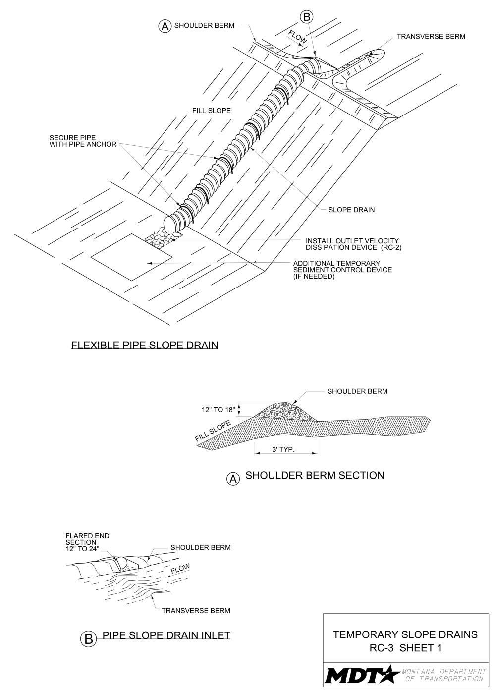
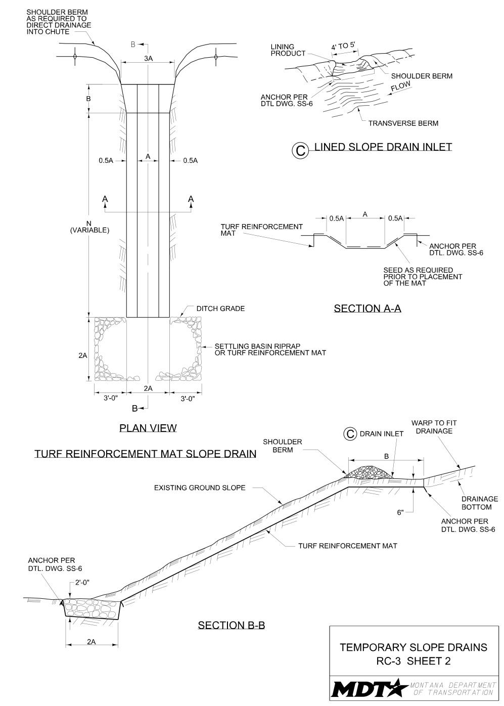
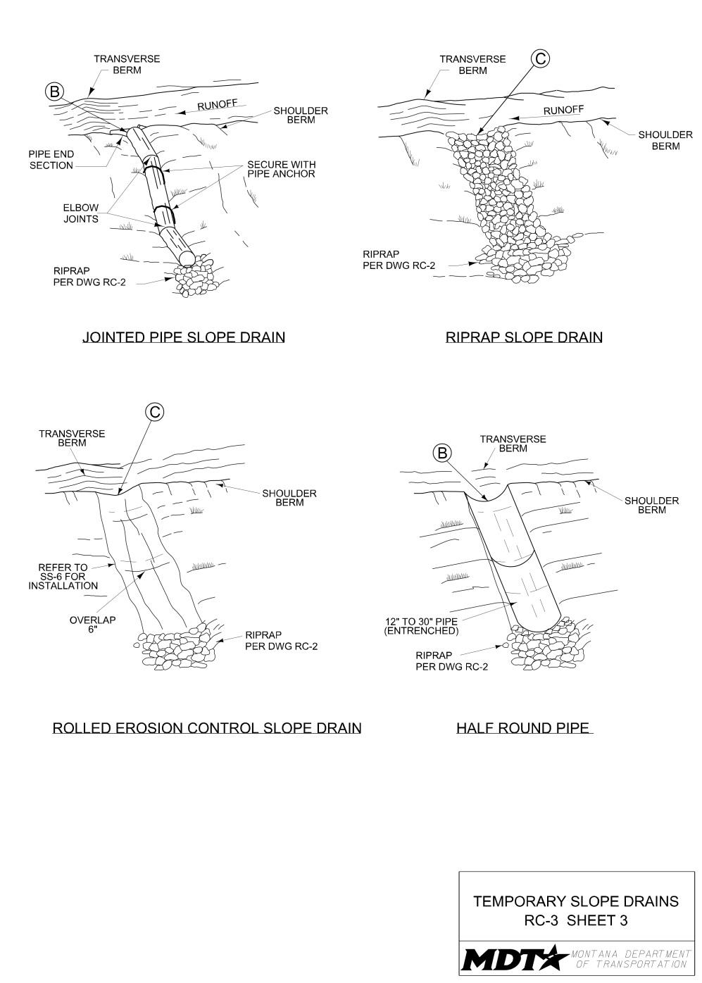
Definition and Purpose
A temporary linear sediment barrier of permeable fabric designed to intercept and slow the flow of sediment-laden sheet flow runoff. Silt fences allow sediment to settle from runoff before water leaves the construction site. Use silt fence between the edge of construction disturbance and a critical resource or right-of-way line that is adjacent to the construction activity.
AT A GLANCE
Objectives
☐ Construction Site Planning ☒ Temporary Soil Stabilization ☒ Run-on and Runoff Control ☒ Temporary Sediment Control ☐ Snow Management ☐ Good Housekeeping ☒ Waste Management
Applications
☒ Site Perimeter ☐ Inlets and Outlets ☐ Exposed Areas ☐ Sediment Traps/Basins ☐ Slopes ☒ Near Water/Wetlands ☒ Toe of Slopes ☒ Pollution/Material ☐ Ditches Sources ☐ Cut/Fill Transitions
Source: MDT
Alternative BMPs to Consider
• SC-9 Sandbag Barrier • SC-11 Rock Filter Berm • SC-10 Gravel Bag
Berm
Use In Conjunction With
• CP-1 Scheduling • SS-1 Preservation of
Existing Vegetation/
Vegetated Buffers • SS-4 Erosion Seeding • SS-7 Surface Roughening • SC-6 Fiber Rolls • SC-7 Compost Sock • SC-8 Brush Barrier
Limitations
• Not effective unless trenched and keyed in. • Must be maintained to remain effective. • Not intended for use in streams, channels, or anywhere flow is concentrated.
Install silt fence parallel to contours with space for sediment storage.
Do not install silt fence in areas of concentrated flow.
Source: MDT
• Fabric life span is generally limited, often ranging from five to eight months. Longer periods of use may require fabric replacement. • Do not use silt fences to divert flow. • Do not use below slopes subject to creep, slumping, or landslides. • Difficult to install and maintain in windy areas. • Must be removed and disposed of properly.
Effectiveness
• Most effective when used in combination with upgradient BMPs that control erosion and stabilize soils. • Least effective when not maintained and sediment is allowed to accumulate.
Materials
• Use fence posts at least 48 inches in length having a sufficient strength to resist damage during installation and to support the applied loads due to material build up behind the silt fence. For clear zone applications, use a maximum post length of 60 inches in length. • For stabilized silt fence, use woven wire having a maximum of 6-inch mesh spacing and a minimum of 14.5 gauge wire. • Furnish temporary silt fence geotextile in accordance with the contract.
Design and Installation
• Silt fence is a single or series of filter fabric sediment barriers stretched and attached to supporting posts. The fence bottom is entrenched. There are two types of silt fence installations. 1. Unstabilized. Silt fence supported with either wood or metal fence posts. 2. Stabilized. Silt fence supported with metal posts and with woven wire backing. • Position the silt fence barrier to prevent sediment from entering drainages. Do not place the barrier across live steams or where concentrated flows may occur.
Woven wire backing is required for heavier flow velocities and sediment. • Distances between silt fence when used for sediment retention are as follows. - For slopes of 2% to 3%, place silt fence at 500-foot spacing. - For slopes of 3% to 4%, place silt fence at 300-foot spacing. - For slopes greater than 4%, place silt fence at 150-foot spacing. • Install silt fences prior to disturbing areas requiring this BMP or as slope grades are achieved. • Place silt fence continuous and transverse to the flow. Follow the contours of the site as closely as possible. Place the fence so that water cannot run off and around the end of the fence. • Slope of areas draining to fence should generally be no steeper than 2:1 H:V (horizontal:vertical). For slopes steeper than 2:1, consider alternative soil stabilization BMPs. • The slope upgradient of the silt fence should generally be a maximum of 200 feet in length to minimize flow volumes and velocities and increase the effectiveness of the silt fence. • Limit to locations suitable for temporary ponding or deposition of sediment. Do not use where rocky or hard soils will prevent uniform installation of posts and entrenching of fabric. • For slopes adjacent to water bodies, use additional soil stabilization BMPs. • Use silt fence in conjunction with soil stabilization source controls up slope to provide effective control. • Do not excavate trenches wider and deeper than necessary for proper installation. • Excavate trenches immediately before installation of the temporary linear sediment barriers. • Construct the silt fence with a setback from the toe of a slope, where practicable, to allow for storm water ponding and sediment storage.
Design and Installation
• Construct the length of each silt fence section so that the change in base elevation along the section does not exceed 1/3 the height of the barrier. This will minimize the chance of storm water from higher elevation areas traveling along the silt fence from overtopping the silt fence in lower elevation areas. Each silt fence reach should generally be limited to 500 feet in order to minimize the amount of water that may accumulate in lower elevation areas. • Excavate a trench at least 6 inches wide by 6 inches deep at the base of the silt fence. Utilizing a J configuration, bury the silt fence in the trench a minimum of 6 inches below the ground surface and a minimum of 6 inches horizontally along the bottom of the trench. If the fence requires replacement due to failure from pullout or undercutting, the subsequent entrenchment must include both vertical and horizontal entrenchment components in a J configuration. Backfill the trench with the excavated material and compact. • Securely fasten the silt fence geotextile to the upslope side of the fence post. • For silt fence joints, join posts as shown in the drawing, rotate 180° counterclockwise, and drive into the ground. Overlap posts so no gaps exist in silt fence. • Install cross barriers (barriers that limit water movement laterally along the length of the silt fence) with a minimum height of 1/3 and a maximum height of 1/2 the height of the silt fence. Cross barrier placement is illustrated in the drawing.
Inspection and Maintenance
• Provide regular inspections at the frequency required by the NPDES/MPDES storm water permit to ensure silt fence is maintained and functions properly. If no storm water permit is required for the project, conduct inspections as specified in the contract. • Remove sediment from behind the fence when it accumulates to 1/3 the original height. • Dispose of removed sediment in accordance with all laws, rules, and applicable regulations. • Repair or replace damaged silt fence immediately. Typical silt fence damage includes, but is not limited to: undercutting, splits, tears, slumping/sagging, and weathered fabric. • Inspect all temporary silt fences immediately after each rainfall. Immediately correct any deficiencies. • Review silt fences in areas where construction activities have altered the natural contour and drainage runoff to ensure that the silt fences are properly located for effectiveness. Install additional silt fences or other appropriate BMPs where deficiencies exist.
Removal
• Either grade and seed, or remove sediment deposits behind silt fence prior to removal. • Remove silt fence when up-slope area has been stabilized, when replaced with an alternate BMP, or upon completion of the work. • Dispose of removed sediment and waste materials in accordance with all laws,
Removal
rules, and applicable regulations. • Fill and compact postholes and anchorage trench and grade fence alignment to blend with adjacent ground.
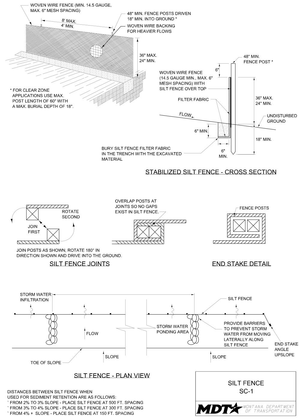
Definition and Purpose
A temporary basin formed by excavation and/or constructing an embankment so that sediment-laden runoff is temporarily detained under slow flowing conditions, allowing sediment to settle out before the runoff is discharged.
AT A GLANCE
Objectives
☐ Construction Site Planning ☐ Temporary Soil Stabilization ☒ Run-on and Runoff Control ☒ Temporary Sediment Control ☐ Snow Management ☐ Good Housekeeping ☐ Waste Management
Applications
☐ Site Perimeter ☐ Inlets and Outlets ☐ Exposed Areas ☒ Sediment Traps/Basins ☐ Slopes ☐ Near Water/Wetlands ☐ Toe of Slopes ☐ Pollution/Material ☐ Ditches Sources ☐ Cut/Fill Transitions
Alternative BMPs to Consider
• SC-3 Sediment Trap
Use In Conjunction With
• CP-1 Scheduling • RC-1 Earth Dikes/
Drainage Swales/
Lined Ditches • RC-2 Outlet Velocity
Dissipation Devices • RC-3 Temporary Slope
Drains • SC-1 Silt Fence
Limitations
• Alternative BMPs must be thoroughly investigated for erosion control before selecting temporary desilting basins. • Large surface areas may be needed to allow sediment to settle. • Generally not appropriate for drainage areas greater than 75 acres. • Size may be limited by availability of right-of-way.
Source: Tom Gore
Typical desiliting basin with perforated riser pipe. Size basin in relation to the drainage area conveying to the feature.
Effectiveness
• Most effective to address contributing areas between 5 acres and 10 acres. • Least effective when sediment removal is not performed to maintain the required sediment storage capacity.
Materials
• Principal outlet typically consists of a corrugated metal, HDPE, or reinforced concrete riser pipe with dewatering holes and an anti-vortex device and trash rack attached to the top of the riser. • Turf reinforcement mats and crushed stone or 3/4-inch gravel for inlet, outlet, emergency spillway, and riser protection.
Design and Installation
• Limit the contributing area of the desilting basin to only the runoff from the disturbed soil areas. Use temporary concentrated flow conveyance controls to divert runoff from undisturbed areas away from the desilting basin. • Use desilting basins for disturbed areas between 5 acres and 10 acres where sediment-laden water may enter the drainage system or watercourse. • Do not use desilting basins for drainage areas greater than 75 acres and do not locate basins within live streams. • Design and locate desilting basins so that they can be maintained. Construct desilting basins prior to construction activities. • Regardless of size and storage volume, include features in desilting basins to accommodate overflow or bypass flows that exceed the design storm event. • Design basins to drain within 72 hours following storm events. • Provided adequate outlet protection to prevent erosion and scouring of the embankment and channel (see RC-2). • Locate basins (1) by excavating a suitable area or where a low embankment can be constructed across a swale, (2) where post-construction (permanent) detention basins will be constructed, (3) where failure would not cause loss of life or property damage, and (4) to provide access for maintenance on a year-round basis, including sediment removal, sediment stockpiling in a protected area, and to maintain the basin to provide the required capacity. • Clear and strip areas where embankments, structural works, and desilting basin will be constructed. • Locate basin inlets to maximize travel distance to the basin outlet. Generally, a basin length equal to twice the basin width provides adequate travel distance. • Use rock or vegetation to protect the basin inlet and slopes against erosion. • A forebay (a reservoir or channel constructed upstream of the basin) may be provided to remove debris and larger particles. • Securely anchor the outlet pipe to prevent floatation. • Mark the maximum allowed sediment level on the outlet riser pipe. • Avoid dewatering of groundwater to the desilting basin during the rainy season.
Insignificant quantities of accumulated precipitation may be dewatered to the desilting basin unless precipitation is forecasted within 24 hours. • Chain link fencing around each desilting basin may be installed to prevent unauthorized entry to the basin or if safety is a concern. • Provide an outlet designed to handle peak flows.
Design and Installation Outlet #1, See Drawing SC-2
- Perforate the top 2/3 of the riser. Typically, perforations consisting of 1/2-inch diameter holes spaced 8 inches vertically and 10 to 12 inches horizontally are sufficient. - Place 3/4-inch gravel over perforated holes to approximately 2 inches minimum thickness to help prevent clogging of dewatering holes.
Outlet #2, See Drawing SC-2
- Provide two 1 inch diameter holes above the sediment storage volume on opposite sides of the non-perforated riser pipe. This will generally provide sufficient detention time for basins to drain approximately 10 acres. - Construct an emergency spillway to accommodate flows not carried by the principal spillway. Provide an open-channel spillway (earthen or vegetated) over undisturbed material (not fill) or armored with riprap.
Outlet #3, See Drawing SC-2
- Perforate the lower 1/2 of the riser pipe. Typically, perforations consisting of 1/2-inch diameter holes spaced approximately 3 inches apart, in each outside corrugation (for corrugated metal pipe), are sufficient. - Place 3/4-inch gravel over perforated holes to approximately 2 inches minimum thickness to help prevent clogging of dewatering holes.
Inspection and Maintenance
• Provide regular inspections at the frequency required by the NPDES/MPDES storm water permit to ensure desilting basins are functioning properly. If no storm water permit is required for the project, conduct inspections as specified in the contract. • Inspect temporary desilting basins before and after rainfall events. • Examine basin banks for seepage and structural soundness. • Check inlet and outlet structures and spillway for any damage or obstructions.
Repair damage and remove obstructions as needed. • Check inlet and outlet area for erosion and stabilize if required. • Remove sediments when storage zone is 1/3 full. • Check fencing for damage and repair as needed.
Removal
• Remove desilting basins when no longer needed, or upon completion of the work. • When removed, fill in, regrade, and stabilize basins. Incorporate removed sediment into the project or dispose of it in accordance with all laws, rules, and applicable regulations.

Definition and Purpose
A temporary basin with a controlled release structure, formed by excavating or constructing an earthen embankment across a waterway or low drainage area.
AT A GLANCE
Objectives
☐ Construction Site Planning ☐ Temporary Soil Stabilization ☒ Run-on and Runoff Control ☒ Temporary Sediment Control ☐ Snow Management ☐ Good Housekeeping ☐ Waste Management
Applications
☐ Site Perimeter ☐ Inlets and Outlets ☐ Exposed Areas ☒ Sediment Traps/Basins ☐ Slopes ☐ Near Water/Wetlands ☐ Toe of Slopes ☐ Pollution/Material ☐ Ditches Sources ☐ Cut/Fill Transitions
Alternative BMPs to Consider
• SC-2 Desilting Basin
Use In Conjunction With
• CP-1 Scheduling • RC-1 Earth
Dikes/Drainage
Swales/Lined Ditches • RC-2 Outlet Velocity
Dissipation Devices • RC-3 Temporary Slope
Drains • SC-10 Gravel Bag Berm
Limitations
• Requires large surface areas to allow sediment to settle. • Not appropriate for drainage areas greater than 5 acres. • Only removes large and medium-sized particles and requires up-gradient erosion control. • Not to be located in live streams. • Size may be limited by availability of right-of-way.
Source: Tom Gore
Properly-installed sediment traps will include an armored wier with a low point for discharge.
Lack of an armored weir will lead to failure/erosion at the discharge location.
Source: Tom Gore
Effectiveness
• Most effective when used in combination with up-gradient erosion control measures. • Least effective when sediment removal is not performed to maintain the required sediment storage capacity.
Materials
• Crushed stone/gravel outlet weir section.
Design and Installation
• Construct sediment traps prior to rainy season and construction activities. • Located traps where (1) a low embankment can be constructed across a swale, (2) failure would not cause loss of life or property damage, and (3) access for maintenance is convenient. • Size traps to accommodate both a settling zone and sediment storage zone with recommended minimum volumes of 70 CY/acre and 35 CY/acre of contributing drainage area, respectively, based on 1/2 inch of runoff volume over a 24-hour period. Multiple traps and/or additional volume may be required to accommodate site-specific rainfall and soil conditions. • Provide a design which accommodates maintenance requirements, such as sediment and vegetation removal, to ensure continuous function of the trap outlet. • Clear and strip areas where embankments, structural works, and sediment traps will be constructed. • Locate trap inlets to maximize travel distance to the trap outlet. Generally, a trap length equal to three times the trap width provides adequate travel distance. • Use rock or vegetation to protect the trap outlets against erosion. • Chain link fencing around large sediment traps may be installed to prevent unauthorized entry to the trap or if safety is a concern. • To dewater the trap, construct a crushed stone outlet section of the embankment at the low point of the trap. The stone section serves as a non-erosive spillway outlet for flood flows and the bottom section provides a means of dewatering the trap between rainfall events.
Inspection and Maintenance
• Provide regular inspections at the frequency required by the NPDES/MPDES storm water permit to ensure sediment traps are functioning properly. If no storm water permit is required for the project, conduct inspections as specified in the contract. • Inspect sediment traps before and after rainfall events. • Check trap banks for seepage and structural soundness. • Check outlet structure and spillway for any damage or obstructions. Repair damage and remove obstructions as needed. • Check outlet area for erosion and stabilize if required. • Remove accumulated sediment when the volume has reached 1/3 the original trap volume. • Check fencing for damage and repair as needed.
Removal
• Remove the trap when no longer needed or upon completion of the work. • When removed, fill in, regrade, and stabilize sediment trap locations. Incorporate any remaining captured sediment into the project, or dispose of it in accordance with all laws, rules, and applicable regulations.
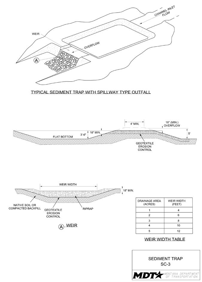
Definition and Purpose
A small dam constructed across a natural or man-made channel or drainage ditch. Check dams reduce scour and channel erosion by reducing velocity of concentrated flows and encouraging sediment dropout.
AT A GLANCE
Objectives
☐ Construction Site Planning ☒ Temporary Soil Stabilization ☒ Run-on and Runoff Control ☒ Temporary Sediment Control ☐ Snow Management ☐ Good Housekeeping ☐ Waste Management
Applications
☐ Site Perimeter ☐ Inlets and Outlets ☐ Exposed Areas ☐ Sediment Traps/Basins ☐ Slopes ☐ Near Water/Wetlands ☐ Toe of Slopes ☐ Pollution/Material ☒ Ditches Sources ☐ Cut/Fill Transitions
Alternative BMPs to Consider
• Not Applicable.
Source: Tom Gore
Place check dams at a distance and height to allow small pools to form behind them.
Curve compost socks upstream to prevent runoff from flowing around the sock.
Use In Conjunction With
• CP-1 Scheduling • SS-6 Rolled Erosion
Control Products • RC-1 Earth Dikes/
Drainage Swales/
Lined Ditches • RC-2 Outlet Velocity
Dissipation Devices • SC-7 Compost Socks • SC-9 Sandbag Barrier
Limitations
• Do not use in live, flowing streams. • Not appropriate in channels which drain areas greater than 10 acres.
Source: Tom Gore
• Should not be placed in channels, which are already vegetated unless erosion is expected, as installation may damage vegetation. • Require extensive maintenance following high velocity flows and may have to be replaced. • Promotes sediment trapping which can be re-suspended during subsequent storms or removal of the check dam. • Can be difficult to seed around. • Type of Installation may be affected if installed within clear zone. • Cannot be constructed from silt fence.
Effectiveness
• Most effective when constructed with a lowpoint/spillway, properly secured, and keyed in to the bottom and sides of the channel. • Least effective if not maintained and allowed to fill up with sediment.
Materials
• A check dam is a small dam that can be constructed of gravel, sandbags, compost socks, or an appropriate manufactured product. • Check dams constructed from gravel must be 100% passing the 2-inch screen and 10% maximum passing the No. 4 sieve. Dam material may be pit run or crushed aggregate. • Refer to SS-7 Compost Socks and SS-9 Sandbag Barrier for material requirements.
Design and Installation
• Check dams may be installed in small channels with drainage areas of 10 acres or less and/or channels with steep profile grades (greater than 5%). • Check dams cannot be used in live streams. • Check dams cannot be constructed from silt fence or fiber rolls. • Construct check dams wide enough to reach from bank to bank of the channel or swale. • Construct check dams to include a spillway at the center of the dam that is at least 6 inches lower than the existing ground at the outer edges of the check dam. • Secure check dam in place. With the exception of compost socks, trench check dam below grade, and key check dam back into the adjoining grade. • Key rock check dams into the sides and bottom of the channel, minimum 4 inches. • Install manufactured check dams in accordance with submitted manufacturer’s specifications. • If placing the check dams after an outfall device, install the first check dam approximately 15 feet from the outfall device and at regular intervals after that. • Place check dams at a distance and height to allow small pools to form behind them. • The maximum height for check dams within the clear zone is 6 inches. • As a general rule, the maximum spacing between dams should be such that the toe of the upstream dam is at the same elevation as the top of the downstream dam. • Based on the criteria above, distances between check dams for a 2-foot-high dam, given the various ditch slopes, are as follows. - 1% ditch slope: place check dams at 200-foot spacing - 2% ditch slope: place check dams at 100-foot spacing - 3% ditch slope: place check dams at 67-foot spacing - 4% ditch slope: place check dams at 50-foot spacing - 5% ditch slope: place check dams at 40-foot spacing - 6% ditch slope: place check dams at 33-foot spacing • A second criterion can be used to determine spacing.
D= Check Dam Height (feet) % Channel Slope X 100
• Design check dams so high flows (typically a 2-year storm or larger) safely flow over the check dam without an increase in upstream flooding or damage to the check dam.
Inspection and Maintenance
• Provide regular inspections at the frequency required by the NPDES/MPDES storm water permit to ensure check dams are maintained and function properly. If no storm water permit is required for the project, conduct inspections as specified in the contract. • Inspect check dams routinely, particularly after each storm event. • Inspect for erosion along the edges, washouts, undermining, and clogging. • Repair damage as needed. • Remove sediments when depth reaches 1/2 of the check dam height. • Incorporate removed sediment into the project or dispose of it in accordance with all laws, rules, and applicable regulations.
Removal
• Remove check dams and accumulated sediment when no longer needed or upon completion of the work. • Where grass is used to line ditches, remove check dams when grass has matured sufficiently to protect the ditch or swale. Seed and mulch the area beneath the check dam immediately after removal.
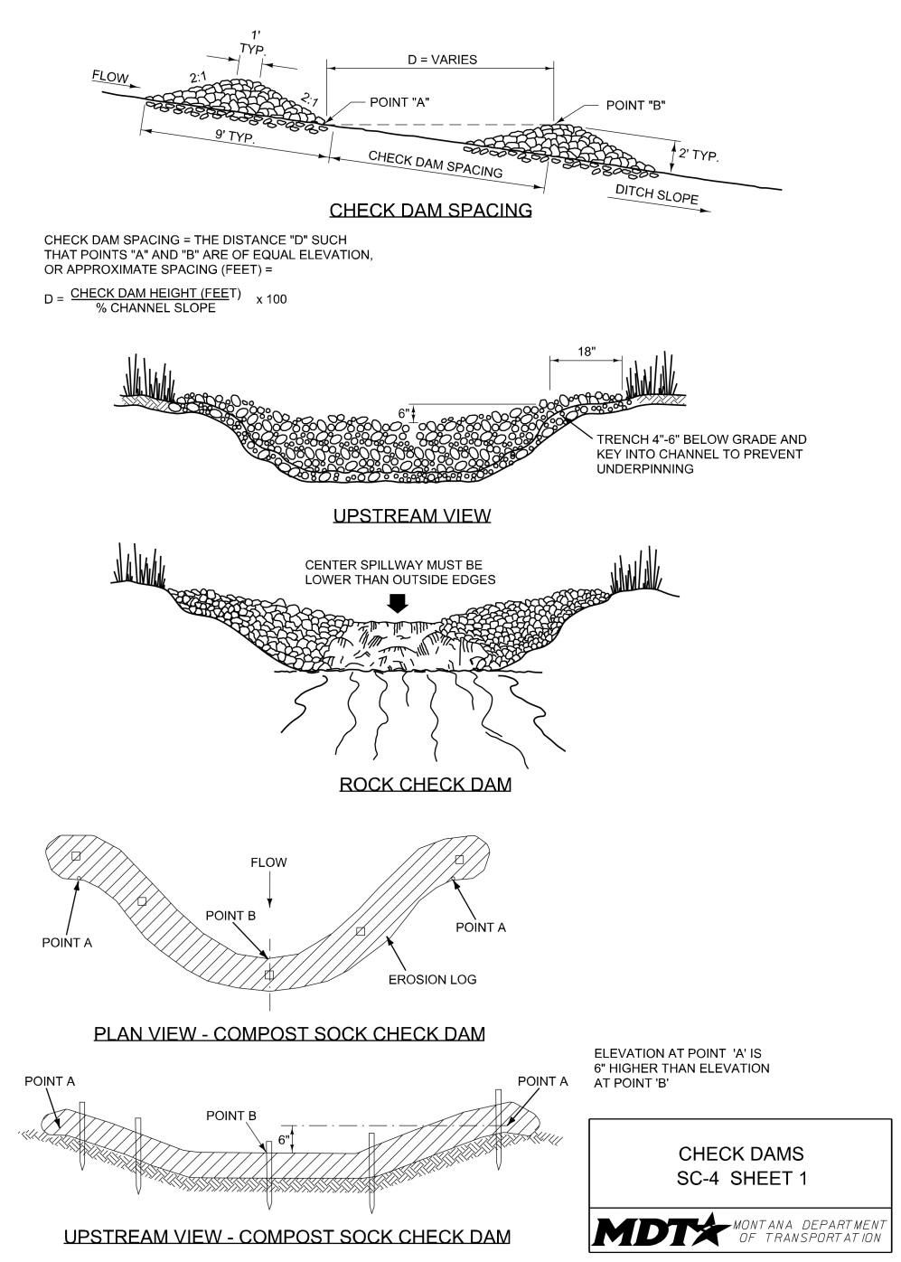

Definition and Purpose
Consist of one or a series of small dugout basins located within a flow channel. Sometimes referred to as “scraper dips,” dugout ditch basins are used to reduce runoff velocity, promote sediment retention and allow settling within longitudinal roadside ditches in a cut section or as longitudinal sediment retention basins at the toe of fills.
AT A GLANCE
Objectives
☐ Construction Site Planning ☐ Temporary Soil Stabilization ☒ Run-on and Runoff Control ☒ Temporary Sediment Control ☐ Snow Management ☐ Good Housekeeping ☐ Waste Management
Applications
☐ Site Perimeter ☐ Inlets and Outlets ☐ Exposed Areas ☐ Sediment Traps/Basins ☐ Slopes ☐ Near Water/Wetlands ☒ Toe of Slopes ☐ Pollution/Material ☒ Ditches Sources ☐ Cut/Fill Transitions
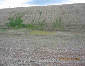
Alternative BMPs to Consider
• SC-4 Check Dams
Use In Conjunction With
• CP-1 Scheduling • RC-1 Earth Dikes/Drainage Swales/Lined Ditches
Limitations
• Cannot be used in live streams. • Cannot be placed in channels which are already grass lined unless erosion is expected, as installation may damage vegetation. • Requires maintenance following high velocity flows. • Promotes sediment trapping which can be resuspended during subsequent storms if not maintained. • May create difficult conditions to seed in and around.
Source: MDT
Properly-installed dugout ditch basins are placed at a depth that allows small pools to form in them.
Effectiveness
• Most effective when sized and spaced based on anticipated flow and degree of ditch slope. • Least effective in very sandy soils where the structure of the basin could be relatively unstable.
Materials
• Not applicable.
Design and Installation
• Place dugout ditch basins at a depth that allows small pools to form in them. • Basins should be 6 to 12 inches deep and a minimum 10 to 12 feet long. Sizing depends on the amount of flow expected and anticipated sediment storage requirements. • The maximum height for dugout ditch basins if used inside the clear zone is 6 inches. • The distance between dugout ditch basins is dependent on the length of ditch section relating to the grade that needs sediment retention. Utilize the following interval spacing.
Ditch Slope Dugout Ditch Basin Spacing
2% to 3% Slopes 300 feet 3% to 4% Slopes 150 feet 4% + Slopes 50 feet
• The dugout ditch basin spacing values are empirical and are the maximal interval distances for a 2-year, 24-hour rain event. Intervals may be shortened if dictated by soil conditions and/or precipitation.
Inspection and Maintenance
• Provide regular inspections at the frequency required by the NPDES/MPDES storm water permit to ensure dugout ditch basins are maintained and function properly. If no storm water permit is required for the project, conduct inspections as specified in the contract. • Inspect basins regularly, prior to predicted storm events, and as soon as possible after each storm event. • Repair damage to basins as needed to maintain functionality. If dugout ditch basins are required for the duration of the project, sediment may need to be removed when depth reaches 1/2 of the basin height.
Removal
• With MDT approval, dugout ditch basins may remain in place and be seeded during permanent seeding of the ditch. • If ditch basins are removed, fill in, regrade, and stabilize basin locations. Incorporate removed sediment into the project or dispose of it in accordance with all laws, rules, and applicable regulations.
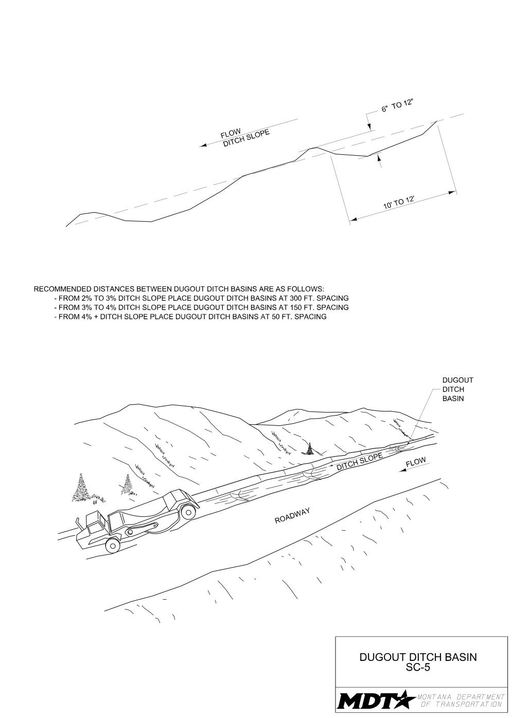
Definition and Purpose
Weed–free straw, flax, coconut, or other similar fiber materials bound into tight tubular rolls encased in natural fiber or UV-degradable polypropylene netting. They are used to intercept runoff, reduce flow velocities, capture sediment, and promote infiltration.
AT A GLANCE
Objectives
☐ Construction Site Planning ☒ Temporary Soil Stabilization ☒ Run-on and Runoff Control ☒ Temporary Sediment Control ☐ Snow Management ☐ Good Housekeeping ☐ Waste Management
Applications
☒ Site Perimeter ☒ Inlets and Outlets ☒ Exposed Areas ☐ Sediment Traps/Basins ☒ Slopes ☒ Near Water/Wetlands ☒ Toe of Slopes ☒ Pollution/Material ☐ Ditches Sources ☒ Cut/Fill Transitions
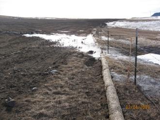
Alternative BMPs to Consider
• SS-7 Surface • SC-7 Compost Sock
Roughening • SC-8 Brush Barrier • SC-1 Silt Fence • SC-10 Gravel Bag Berm
Source: MDT
Properly-installed fiber rolls are trenched in and run parallel to slope contours.
Fiber rolls must be overlapped and tightly abutted to prevent storm water flows and sediment from passing between rolls.
Use In Conjunction With
• SS-2 Mulch Cover • SS-3 Temporary
Seeding • SS-4 Erosion Seeding • SS-5 Soil Binders • SS-6 Rolled Erosion
Control Products • SS-7 Surface Roughening • SC-4 Check Dams • SC-12 Inlet/Outlet
Protection
Limitations
• Not for use in live streams. • Erosion may occur if fiber rolls are not adequately trenched in. • Fiber rolls are difficult to move once saturated. • Fiber rolls can be removed by unexpected high flows if not properly staked and trenched in. • Fiber rolls have a limited sediment capture zone, and more effective sediment barriers may need to be considered. • Do not use fiber rolls on slopes subject to creep, slumping, or landslide.
Source: MDT
Effectiveness
• Most effective when sized for appropriate application and anticipated runoff flows and when trenched in and properly staked. • Least effective when flattened by traffic or overwhelmed with sediment.
Materials
• Provide fiber rolls consisting of either prefabricated rolls (wattles) or rolled tubes of erosion control blanket. • Prefabricated rolls (wattles) should be manufactured from natural straw, coir (coconut), flax, wood fibers, or a combination thereof, and wrapped in netting made of UV-degradable polypropylene or natural fiber such as jute, cotton, hemp, sisal, or burlap. • Refer to SS-6 Rolled Erosion Control Products for erosion control blanket material guidelines for rolled tubes. Secure the ends tightly with jute-type twine.
Design and Installation Assembly of Field-rolled Fiber Roll
• Roll length of erosion control blanket into a tube of minimum 8-inch diameter. • Bind roll at each end and every 4 feet along length of roll with jute-type twine.
Perimeter Control
• Size fiber rolls appropriately depending on use. Factors influencing diameter of roll to be used include slope ratio, anticipated flow volumes, and soil characteristics.
Provide fiber rolls with a minimum diameter of 8 inches or according to submitted manufacturer’s specifications for appropriate design diameter. • Install fiber rolls parallel to the contour line and perpendicular to the direction of flow. • Trench fiber rolls a minimum 2 inches below the ground surface. • Use the following staking method, unless Contractor submits alternative manufacturer staking specifications to MDT. - Stake fiber roll to the ground using a minimum 3/4-inch by 3/4- inch wood stake. Extend stake 12 inches below the ground surface. Space stakes 4 feet apart along entire length of roll. • If more than one roll is placed in a row, overlap the fiber rolls and butt them tightly together. Provide a minimum of 12 inches of overlap. • Turn terminal ends of roll upslope 24 to 48 degrees to prevent flow around ends of roll.
Slope Protection/Toe of Slope
• Do not use fiber rolls where creeping, slumping, or sliding of the slope may occur. • Roll diameter is dependent on the gradient of the slope, anticipated flow volumes, and soil characteristics. Spacing of the roll is dependent on gradient of the slope and diameter of roll.
Provide fiber rolls with a minimum diameter of 8 inches on the slope and 12 inches in diameter at toe of slope, or according to submitted manufacturer’s specifications for appropriate design diameter. Use the following spacing guidelines unless
Contractor submits alternate manufacturer specifications to MDT.
Spacing Intervals Roll Diameter Slope
8 inch 12 inch
1:1 10 feet 15 feet 2:1 20 feet 30 feet 3:1 30 feet 45 feet 4:1 or flatter 40 feet 60 feet
• Install fiber rolls parallel to the contour line and perpendicular to the direction of flow. • For toe of slope application, install the fiber roll with a setback from toe of slope, where practicable, to allow for storm water ponding and sediment storage. • Trench fiber rolls a minimum of 2 inches below the ground surface. • Use the following staking method, unless Contractor submits alternative manufacturer staking specifications to MDT. - Stake fiber roll to the ground using a minimum 3/4-inch by 3/4-inch wood stake. Extend stake 12 inches below the ground surface. Space stakes 4 feet apart along entire length of roll. • If more than one roll is placed in a row, overlap fiber rolls and butt them tightly together. Provide a minimum of 12 inches of overlap. • Turn terminal ends of roll upslope 24 to 48 degrees to prevent flow around ends of roll. • Fiber rolls should extend sufficiently from either side of the flow line to ensure that water flows through the roll rather than around it.
Inlet/Outlet Protection
• Refer to SC-12 Inlet/Outlet Protection for design and installation guidelines. • Fiber rolls must be trenched in a minimum of 2 inches below the ground surface.
Inspection and Maintenance
• Provide regular inspections at the frequency required by the NPDES/MPDES storm water permit to ensure fiber rolls are functioning properly. If no storm water permit is required for the project, conduct inspections as specified in the contract. • Inspect fiber rolls regularly, particularly before forecast storm events and as soon as possible after storm events. • Inspect to ensure rolls remain firmly anchored and trenched. • Inspect for undermining, tears, splits, unraveling, or slumping. • Repair any rills or gullies promptly. Repair or replace fiber rolls as needed. • For all applications except slope protection, remove sediment from the upslope side of the fiber roll when accumulation reaches 1/3 of the effective height of the roll. • Incorporate removed sediment into the project or dispose of it in accordance with all laws, rules, and applicable regulations.
Inspection and Maintenance
• For inlet protection, check all storm drain inlets after each storm event, remove any sediment or debris clogging inlet, and repair the inlet protection to prevent sediment clogging in the future.
Removal
• When fiber rolls are removed, collect and dispose of sediment accumulation and fill, compact, and seed holes, trenches, depressions or any other ground disturbance to blend with adjacent ground. • Dispose of waste materials in accordance with all laws, rules, and applicable regulations.
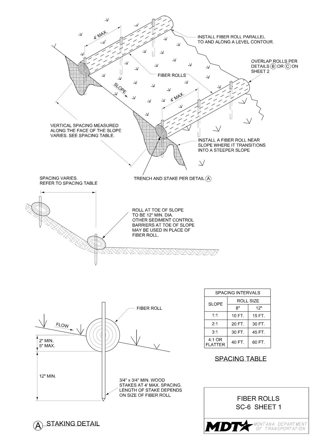
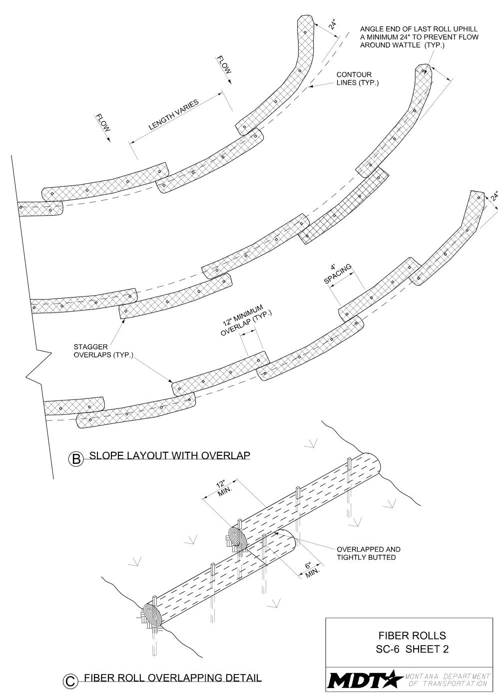
Definition and Purpose
A mesh sock filled with composted material that is placed perpendicular to sheet-flow runoff to control erosion and retain sediment in disturbed areas. The compost socks intercept runoff, reduce flow velocities, promote infiltration, and act as a filter that traps sediment and other pollutants (e.g., heavy metals, hydrocarbons, nutrients) as runoff passes through it.
AT A GLANCE
Objectives
☐ Construction Site Planning ☒ Temporary Soil Stabilization ☒ Run-on and Runoff Control ☒ Temporary Sediment Control ☐ Snow Management ☐ Good Housekeeping ☐ Waste Management
Applications
☒ Site Perimeter ☒ Inlets and Outlets ☒ Exposed Areas ☐ Sediment Traps/Basins ☒ Slopes ☐ Near Water/Wetlands ☒ Toe of Slopes ☒ Pollution/Material ☒ Ditches Sources ☒ Cut/Fill Transitions
Source: MDT
Alternative BMPs to Consider
• SS-7 Surface • SC-6 Fiber Rolls
Roughening • SC-8 Brush Barrier • SC-1 Silt Fence • SC-10 Gravel Bag Berm
Compost socks can be stacked to effectively trap sediment.
Anchor sock by staking through the center, not on one side.
Use In Conjunction With
• CP-1 Scheduling • SS-2 Mulch Cover • SS-3 Temporary
Seeding • SS-4 Erosion Seeding • SS-5 Soil Binders • SS-6 Rolled Erosion
Control Products • SS-7 Surface Roughening • SC-4 Check Dams • SC-12 Inlet/Outlet
Protection
Source: Tom Gore
Limitations
• Socks must have uniform contact with the ground. • Proper staking/anchoring is critical to sock effectiveness and to reduce potential movement of sock by high velocity flows. • Not for use in live streams. • May be cost prohibitive in the absence of local certified compost supplier. • Not as effective in very sandy soils. • Not for use directly upstream from nutrient-impaired water bodies.
Effectiveness
• Most effective when sized correctly for the appropriate application and installed with continuous contact between the soil surface and the compost sock. • Least effective when used in very sandy soils, since compost socks are not trenched in.
Materials
• Select the material and color of the compost sock based on required longevity and site conditions. Provide compost sock material which is photodegradable or biodegradable and of a thickness, strength, and material appropriate to the selected use and project duration. • Provide compost material which is seed free (with the exception of pre-seeded compost socks) and weed free. • Acceptable compost materials consist of agricultural vegetative residuals, leaf/yard trimmings, manure, domestic livestock carcasses, wood residue, or food waste.
Design and Installation
• Compost socks do not have to be trenched in, thereby reducing soil surface disturbance. • Compost socks have greater surface area in contact with the ground than silt fence and fiber rolls. Surface contact improves as the socks become heavy when wetted. • Because they do not have to be trenched, compost socks can be used where other
BMPs are not feasible, such as laid directly on pavement and on frozen ground. • Soil surface must be uniform to ensure continuous contact between the ground and compost sock. Prior to installation, prepare locations by removing brush and rocks to facilitate contact with the ground surface.
Perimeter Control
• Compost socks should be sized appropriately depending on use. Factors influencing diameter of sock to be used include slope ratio, anticipated flow volumes, and soil characteristics. Provide compost socks with a minimum diameter of 8 inches or according to submitted manufacturer’s specifications for appropriate design diameter. • Install compost sock parallel to the contour line and perpendicular to the direction of flow. • Use the following staking method, unless Contractor submits alternative manufacturer staking specifications to MDT. - Stake compost sock to the ground using a minimum 3/4-inch by 3/4-inch wood stake. Extend stake 12 inches below the ground surface. Space stakes 4 feet apart along entire length of sock. • If more than one sock is placed in a row, overlap compost socks and butt them tightly together. Provide a minimum of 12 inches of overlap. • Turn terminal ends of sock upslope 24 to 48 degrees to prevent flow around ends of sock.
Slope Protection/Toe of Slope
• Do not use compost socks where creeping, slumping, or sliding of the slope may occur. • Sock diameter is dependent on the gradient of the slope, anticipated flow volumes, and soil characteristics. Spacing of the socks is dependent on gradient of the slope and diameter of sock.
Design and Installation
• Provide compost socks with a minimum diameter of 8 inches on the slope and 12 inches in diameter at toe of slope, or according to submitted manufacturer’s specifications for appropriate design diameter. Use the following spacing guidelines unless Contractor submits alternate manufacturer specifications to MDT.
Spacing Intervals Sock Diameter Slope
8 inch 12 inch
1:1 10 feet 15 feet 2:1 20 feet 30 feet 3:1 30 feet 45 feet 4:1 or flatter 40 feet 60 feet
• Install compost sock parallel to the contour line and perpendicular to the direction of flow. • For toe of slope application, install the compost sock with a setback from toe of slope, where practicable, to allow for storm water ponding and sediment storage. • Use the following staking method, unless Contractor submits alternative manufacturer staking specifications to MDT. - Stake compost sock to the ground using a minimum 3/4-inch by 3/4-inch wood stake. Extend stake 12 inches below the ground surface. Space stakes 4 feet apart along entire length of sock. • If more than one sock is placed in a row, overlap compost socks and butt them tightly together. Provide a minimum of 12 inches of overlap. • Turn terminal ends of sock upslope 24 to 48 degrees to prevent flow around ends of sock. • Compost socks should extend sufficiently from either side of the flow line to ensure that water flows through the sock rather than around it.
Inlet/Outlet Protection and Check Dams
• Refer to SC-4 Check Dams and SC-12 Inlet/Outlet Protection for design and installation guidelines. • Compost socks do not have to be trenched in for either application.
Inspection and Maintenance
• Provide regular inspections at the frequency required by the NPDES/MPDES storm water permit to ensure compost socks are functioning properly. If no storm water permit is required for the project, conduct inspections as specified in the contract. • Inspect compost socks regularly, particularly before forecast storm events and as soon as possible after storm events. • Inspect to ensure socks remain firmly anchored and have not been damaged. • Inspect for tears or splits in socks or slumping. • Repair rills or gullies promptly, reposition and/or re-anchor socks as necessary.
Inspection and Maintenance
• For all applications except slope protection, remove sediment from the upslope side of the compost sock when accumulation reaches 1/3 of the effective height of the sock. • Incorporate removed sediment into the project or dispose of it in accordance with all laws, rules, and applicable regulations. • For inlet protection, check all storm drain inlets after each storm event, remove any sediment or debris clogging inlet, and repair the inlet protection to prevent sediment clogging in the future.
Removal
• Remove all compost socks once the adjacent area or slope has been stabilized, when no longer required, or upon completion of the work. • For slope applications, compost socks can remain to degrade in place provided netting is bio-degradable. The netting on the compost sock can be cut the length of the sock, allowing the compost material to spread. Do not disturb the adjacent soil during this process.
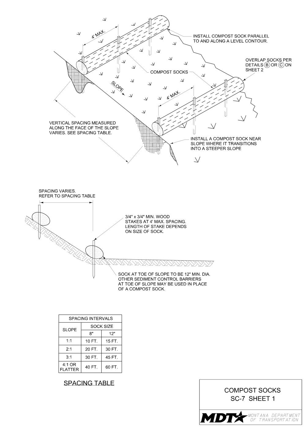

Definition and Purpose
Objectives
A sediment control barrier constructed of ☐ Construction Site Planning material such as small tree branches, root ☒ Temporary Soil Stabilization mats, stone, or other materials left over from ☒ Run-on and Runoff Control site clearing and grubbing. For improved ☐ Temporary Sediment Control efficiency, brush barriers can be covered with a ☐ Snow Managementfilter cloth to stabilize the structure. It is used for the purpose of intercepting sediment laden ☐ Good Housekeeping runoff, allowing runoff to infiltrate and ☐ Waste Management sediment to drop out of suspension. It also provides temporary storage for large amounts of cleared material.
AT A GLANCE
Applications
☒ Site Perimeter ☐ Inlets and Outlets ☒ Exposed Areas ☐ Sediment Traps/Basins ☐ Slopes ☐ Near Water/Wetlands ☒ Toe of Slopes ☐ Pollution/Material ☐ Ditches Sources ☐ Cut/Fill Transitions
Alternative BMPs to Consider
• SC-1 Silt Fence • SC-10 Gravel Bag Berm • SC-9 Sandbag Barrier • SC-11 Rock Filter Berm
Use In Conjunction With
• CP-1 Scheduling • SS-7 Surface Roughening • SC-1 Silt Fence
Limitations
• Brush barriers are not appropriate for high-velocity flow areas. They should only be used in areas of sheet or very low flow. • A large amount of material is needed to construct an effective brush barrier; therefore, alternative sediment controls such as a silt fence may be more appropriate for sites with little material from site clearing. • Can be a visual problem if used in a developed area.
Effectiveness
• Most effective when covered with filter fabric. • Least effective when used in drainage areas that are greater than 0.25 acre per 100 feet of barrier length.
Materials
• On-site material from clearing and grubbing activities that typically includes brush, small limbs, root mats, weeds, vines, soil, rock, and unmarketable timber. • Filter fabric geotextile, wooden stakes, and twine or rope.
Design and Installation
• Limit the drainage area for brush barriers to less than or equal to 0.25 acre per 100 feet of barrier length. Ensure drainage slopes leading down to the barrier do not exceed 2:1 (horizontal:vertical) and are no greater than 100 feet in length. • If a brush barrier is proposed as a stand-alone sediment barrier, cover the barrier with a filter fabric to hold the material in place and increase sediment barrier efficiency. • Provide a brush barrier mound which is a minimum of 3 feet tall and 5 feet wide at its base. Greater dimensions may be appropriate depending on the amount of material available and/or the anticipated runoff flows. • Do not use material with a diameter larger than 6 inches, as this material may be too bulky and create void spaces where sediment and runoff will flow through this barrier. • Construct the brush barrier by piling brush, stone, root mat, and other material from the clearing and grubbing process into a mounded row parallel to the contour line. • Construct the brush barrier with a setback from the toe of a slope, where practicable, to allow for storm water ponding and sediment storage. • Cut filter fabric into lengths sufficient to place across the barrier from its upslope base to just beyond its peak. • Bury the edge of the filter fabric with compacted soil in a trench 4 inches deep and 6 inches wide on the upslope side of the barrier. • Where joints are necessary, overlap the fabric a minimum 6 inches. • Secure filter fabric by fastening it to twine or small-diameter rope that is staked securely on the down-slope side of the barrier. • Unwrapped brush barriers are more successful when used in conjunction with other
BMPs such as silt fence. When used in combination with other BMPs, place brush barriers on the uphill side of the more effective BMP, slowing run-off velocity before contact with the primary sediment-removing BMP.
Inspection and Maintenance
• Provide regular inspections at the frequency required by the NPDES/MPDES storm water permit to ensure brush barriers are maintained and function properly. If no storm water permit is required for the project, conduct inspections as specified in the contract. • Inspect barriers regularly, particularly prior to predicted storm events and as soon as possible after each storm event, to ensure continued effectiveness. • Inspect for breaks, undermining, and channels forming through void spaces. • Inspect the filter fabric for tears and rips and proper anchoring. • Adjust/reconstruct the barrier to repair breaks and undermining and eliminate the channels.
Inspection and Maintenance
• Repair/replace damaged filter fabric and resecure. • Remove accumulated sediments when depth reaches 1/3 of the barrier height. • Incorporate removed sediment into the project or dispose of it in accordance with all laws, rules, and applicable regulations.
Removal
• Remove the brush barrier (and fabric, if applicable) when the adjacent area or slope has been permanently stabilized , when no longer required, or upon completion of the work. • Fill in, compact, and stabilize trenches used to anchor the filter fabric. • Dispose of waste materials in accordance with all laws, rules, and applicable regulations.
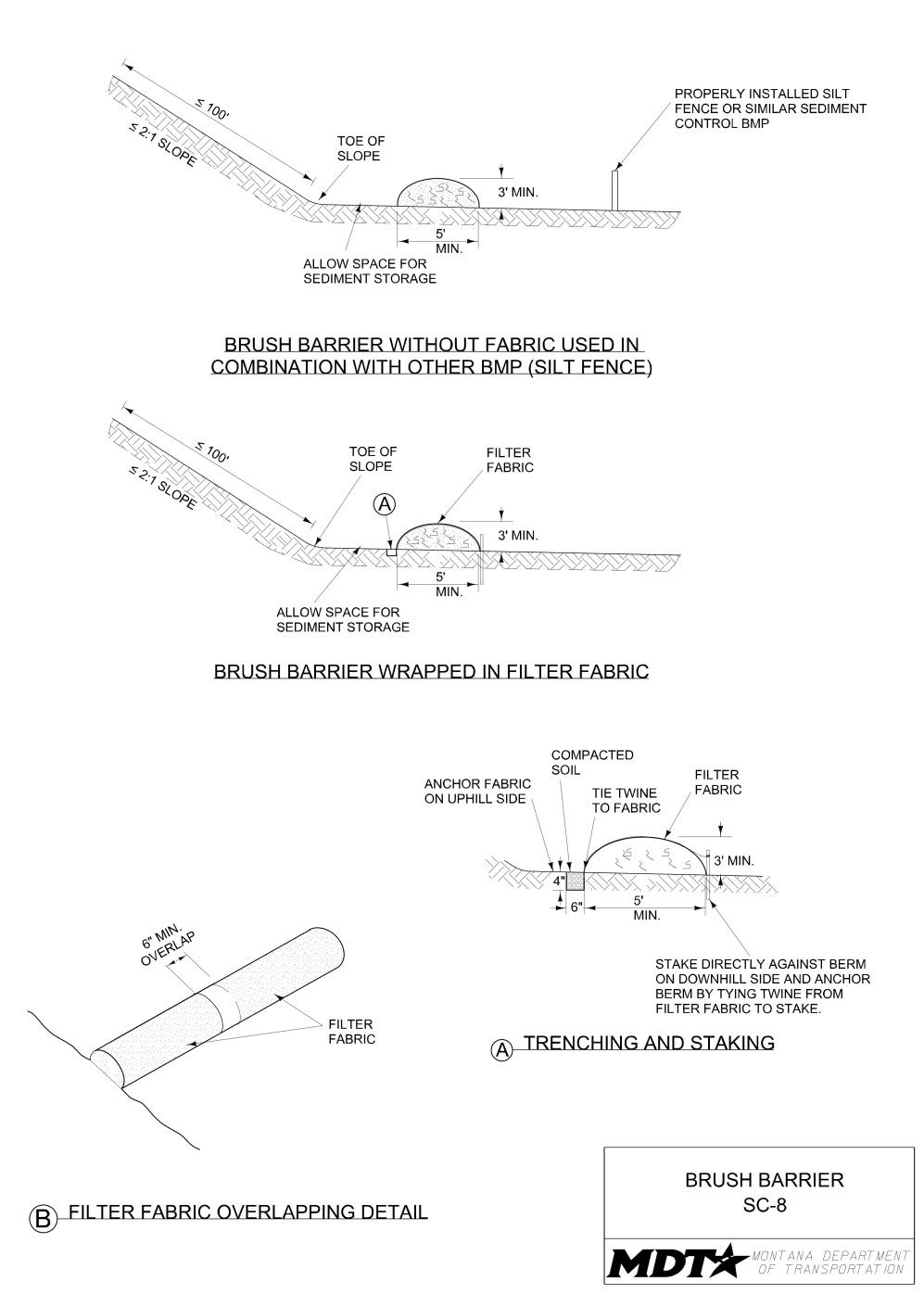
Definition and Purpose
Objectives
A temporary linear sediment barrier consisting ☐ Construction Site Planning of stacked sandbags, designed to intercept and ☒ Temporary Soil Stabilization slow the flow of sediment-laden sheet flow ☒ Run-on and Runoff Control runoff. Sandbag barriers allow sediment to ☒ Temporary Sediment Control settle from runoff before water leaves the ☐ Snow Managementconstruction site. Sandbags can also be used where flows are moderately concentrated, ☐ Good Housekeeping such as ditches, swales, and storm drain inlets ☐ Waste Management (see SC-12 Inlet/Outlet Protection) to divert and/or detain flows.
AT A GLANCE
Applications
☒ Site Perimeter ☒ Inlets and Outlets ☐ Exposed Areas ☐ Sediment Traps/Basins ☒ Slopes ☒ Near Water/Wetlands ☒ Toe of Slopes ☒ Pollution/Material ☒ Ditches Sources ☐ Cut/Fill Transitions
Alternative BMPs to Consider
• SC-1 Silt Fence • SC-8 Brush Barrier • SC-6 Fiber Rolls • SC-10 Gravel Bag Berm • SC-7 Compost Socks • SC-11 Rock Filter Berm
Use In Conjunction With
• CP-1 Scheduling • SS-1 Preservation of
Existing Vegetation/
Vegetated Buffers • SS-2 Mulch Cover • SS-5 Soil Binders SS-6
Rolled Erosion Control
Products • SS-7 Surface
Roughening • SC-1 Silt Fence
Limitations
• Limit upstream drainage area to 5 acres. • Degraded sandbags may rupture when removed, spilling sand. • Installation can be labor intensive. • Limited durability for long-term projects. • When used to detain concentrated flows, maintenance requirements increase.
Effectiveness
• Most effective when used in combination with up-gradient controls. • Least effective when used in highly concentrated flows.
Materials
• Use woven polypropylene, polyethylene, or polyamide fabric or burlap material for bags. • Recommended gravel bag dimensions are as follows: length of 18 inches, width of 12 inches, thickness of 3 inches, and a weight of approximately 35 lb. • Recommended fill material gradation is 100% passing the No. 4 sieve, 50% passing the No. 10 sieve, and 20% maximum passing the No. 200 sieve.
Design and Installation
• When used as a linear control for sediment removal: - Install along a level contour. - Turn ends of sandbag row up slope to prevent flow around the ends. - Size the barrier for the storm water runoff anticipated. A pyramid stacking approach is recommended for greater flows. - Generally, sandbag barriers are used in conjunction with temporary soil stabilization controls up slope to provide effective control. • When used for concentrated flows: - Stack sandbags to required height using a pyramid approach as shown in the drawing. - Install upper rows of sandbags so that they overlap joints in lower rows. - Trench sandbags into ground surface to prevent undermining. • Construct sandbag barriers with a setback from the toe of a slope,where practicable, to allow for storm water ponding and sediment storage.
Inspection and Maintenance
• Provide regular inspections at the frequency required by the NPDES/MPDES storm water permit to ensure sandbag barrier is maintained and functions properly. If no storm water permit is required for the project, conduct inspections as specified in the contract. • Inspect sandbag barriers before and as soon as possible after each storm event. • Reshape or replace sandbags as needed. • Repair washouts or other damages as needed. • Inspect sandbag barriers for sediment accumulations and remove sediments when accumulation reaches 1/3 the barrier height. Incorporate removed sediment into the project or dispose of it in accordance with all laws, rules, and applicable regulations.
Removal
• Remove sandbags when no longer needed. Remove sediment accumulation, and clean, re-grade, and stabilize the area.

Definition and Purpose
A temporary berm consisting of a series of gravel bags that are placed on a level contour to form a barrier across a slope to intercept runoff, reduce runoff velocity, release runoff as sheet flow, and provide some sediment removal.
AT A GLANCE
Objectives
☐ Construction Site Planning ☒ Temporary Soil Stabilization ☒ Run-on and Runoff Control ☒ Temporary Sediment Control ☐ Snow Management ☐ Good Housekeeping ☐ Waste Management
Applications
☒ Site Perimeter ☒ Inlets and Outlets ☐ Exposed Areas ☐ Sediment Traps/Basins ☒ Slopes ☒ Near Water/Wetlands ☒ Toe of Slopes ☒ Pollution/Material ☒ Ditches Sources ☒ Cut/Fill Transitions
Alternative BMPs to Consider
• SC-1 Silt Fence • SC-8 Brush Barrier • SC-6 Fiber Rolls • SC-9 Sandbag Barrier • SC-7 Compost Socks • SC-11 Rock Filter Berm
Source: Tom Gore
Turn ends of gravel bags berms up slope to prevent flow around the ends.
If used as a linear control, tightly abut or overlap. Do not allow gaps between bags.
Use In Conjunction With
• CP-1 Scheduling • SS-1 Preservation of
Existing Vegetation/
Vegetated Buffers • SS-2 Mulch Cover • SS-5 Soil Binders • SS-6 Rolled Erosion
Control Products • SS-7 Surface Roughening • SC-1 Silt Fence
Limitations
• Degraded gravel bags may rupture when removed, spilling contents. • Installation can be labor intensive. • Limited durability for long-term projects. • Can freeze and pose a safety hazard.
Source: Tom Gore
Effectiveness
• Most effective when used in combination with up-gradient controls. • Least effective when used in highly-concentrated flows.
Materials
• Use woven polypropylene, polyethylene, or polyamide fabric or burlap material for bags. • Recommended gravel bag dimensions are as follows: length of 18 inches, width of 12 inches, thickness of 3 inches, and a weight of approximately 35 lbs. • Fill gravel bags approximately 75% full. Recommended fill material gradation is 100% passing the 3/4-inch screen and 10% maximum passing the No. 4 sieve. Fill material may be pit run or crushed aggregate.
Design and Installation
• When used as a linear control for sediment removal: - Install along a level contour. - Turn ends of gravel bags berms up slope to prevent flow around the ends. - Size the berm for the storm water runoff anticipated. A pyramid stacking approach is recommended for greater flows. - Generally, gravel bag berms are used in conjunction with temporary soil stabilization controls up slope to provide effective control. • When used for concentrated flows: - Stack gravel bags to required height using a pyramid approach as shown in the drawing. - Install upper rows of gravel bags so that they overlap joints in lower rows. - Trench gravel bags into ground surface to prevent undermining. • Tightly place gravel bags to minimize gaps between bags. • Place gravel bag berms at 8-foot to 20-foot spacing along slopes. • Construct gravel bag berms with a setback from the toe of a slope,where practicable, to allow for storm water ponding and sediment storage. • Do not use gravel bags within the clear-zone if freezing may occur.
Inspection and Maintenance
• Provide regular inspections at the frequency required by the NPDES/MPDES storm water permit to ensure gravel bag berms are maintained and function properly. If no storm water permit is required for the project, conduct inspections as specified in the contract. • Inspect gravel bag berms before predicted storm events, and as soon as possible after storm events. • Reshape or replace gravel bags as needed. • Inspect gravel bag berms for sediment accumulation and remove sediments when accumulation reaches 1/3 the berm height. Incorporate removed sediment into the project or dispose of it in accordance with all laws, rules, and applicable regulations.
Removal
• Remove gravel bag berms when no longer needed or upon completion of the work. • Remove sediment accumulation, clean, re-grade, and stabilize the area.
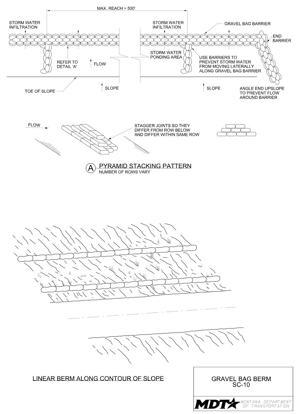
Definition and Purpose
A temporary berm made of aggregate rock material. It is used for the purpose of slowing sediment-laden runoff velocities, allowing runoff to infiltrate and sediment to drop out of suspension.
AT A GLANCE
Objectives
☐ Construction Site Planning ☒ Temporary Soil Stabilization ☒ Run-on and Runoff Control ☒ Temporary Sediment Control ☐ Snow Management ☐ Good Housekeeping ☐ Waste Management
Applications
☒ Site Perimeter ☒ Inlets and Outlets ☐ Exposed Areas ☐ Sediment Traps/Basins ☐ Slopes ☒ Near Water/Wetlands ☒ Toe of Slopes ☒ Pollution/Material ☐ Ditches Sources ☐ Cut/Fill Transitions
Alternative BMPs to Consider
• SC-1 Silt Fence • SC-9 Sandbag Barrier • SC-8 Brush Barrier • SC-10 Gravel Bag Berm
Use In Conjunction With
• CP-1 Scheduling • SS-7 Surface Roughening
Limitations
• Limited life span due to clogging from sediment. • Clogging from mud and soil may make maintenance difficult. • Not intended for use in live streams. • Requires sufficient space for water to pond upslope of berm. • Intended to be used only in gently sloping areas (slopes 10% or less). • More expensive than some other measures because it requires clean gravel or crushed rock rather than materials found onsite.
Effectiveness
• Most effective when berm is properly sized for the anticipated flows and is trenched in. • Least effective if berm becomes clogged with sediment and is not maintained.
Materials
• Construct berms out of angular rock. If angular rock is not available, rounded material may be allowed. • Recommended rock size is 3/4-inch to 3-inch washed, well-graded gravel or crushed rock with less than 5% fines. • Filter fabric geotextile can be used to improve sediment retention and discourage clogging.
Design and Installation
• Locate filter berms on level contours and perpendicular to sheet flow runoff. • For toe of slope application, construct rock filter berms with a setback from toe of slope, where practicable, to allow for storm water ponding and sediment storage. • Size filter berms with a maximum height of 1 foot for installation within the clearzone, and a maximum height of 2 feet elsewhere. • Provide a berm which is a minimum of 2 feet wide at the peak, with 3:1 (horizontal:vertical) or flatter side slopes. • Embed rock filter berm a minimum of 4 inches into the existing ground. • If filter fabric will be used, cut filter fabric into lengths sufficient to place across the berm from its upslope base to just beyond its peak. • Bury the edge of the filter fabric cover with compacted soil in a trench 4 inches deep and 6 inches wide on the upslope side of the berm (see SC-8 Brush Barrier). • Where joints are necessary, overlap the fabric a minimum of 6 inches. • Secure the filter fabric by fastening it to twine or small-diameter rope that is staked securely on the down-slope side of the barrier (see SC-8 Brush Barrier).
Inspection and Maintenance
• Provide regular inspections at the frequency required by the NPDES/MPDES storm water permit to ensure rock filter berms are functioning properly. If no storm water permit is required for the project, conduct inspections as specified in the contract. • Inspect barriers regularly, particularly prior to predicted storm events and as soon as possible after each storm event, to ensure continued effectiveness. • Inspect for washouts, undermining, and clogging. • Reshape or replace rock as needed. • Remove sediment from upslope side when accumulation reaches 1/3 of the berm height. • Incorporate removed sediment into the project or dispose of it in accordance with all laws, rules, and applicable regulations.
Removal
• Remove rock filter berms after adjacent areas and slopes have been stabilized or once construction is complete. • Consider the timing of rock filter berm removal, as removal can cause additional ground disturbance at the berm location.
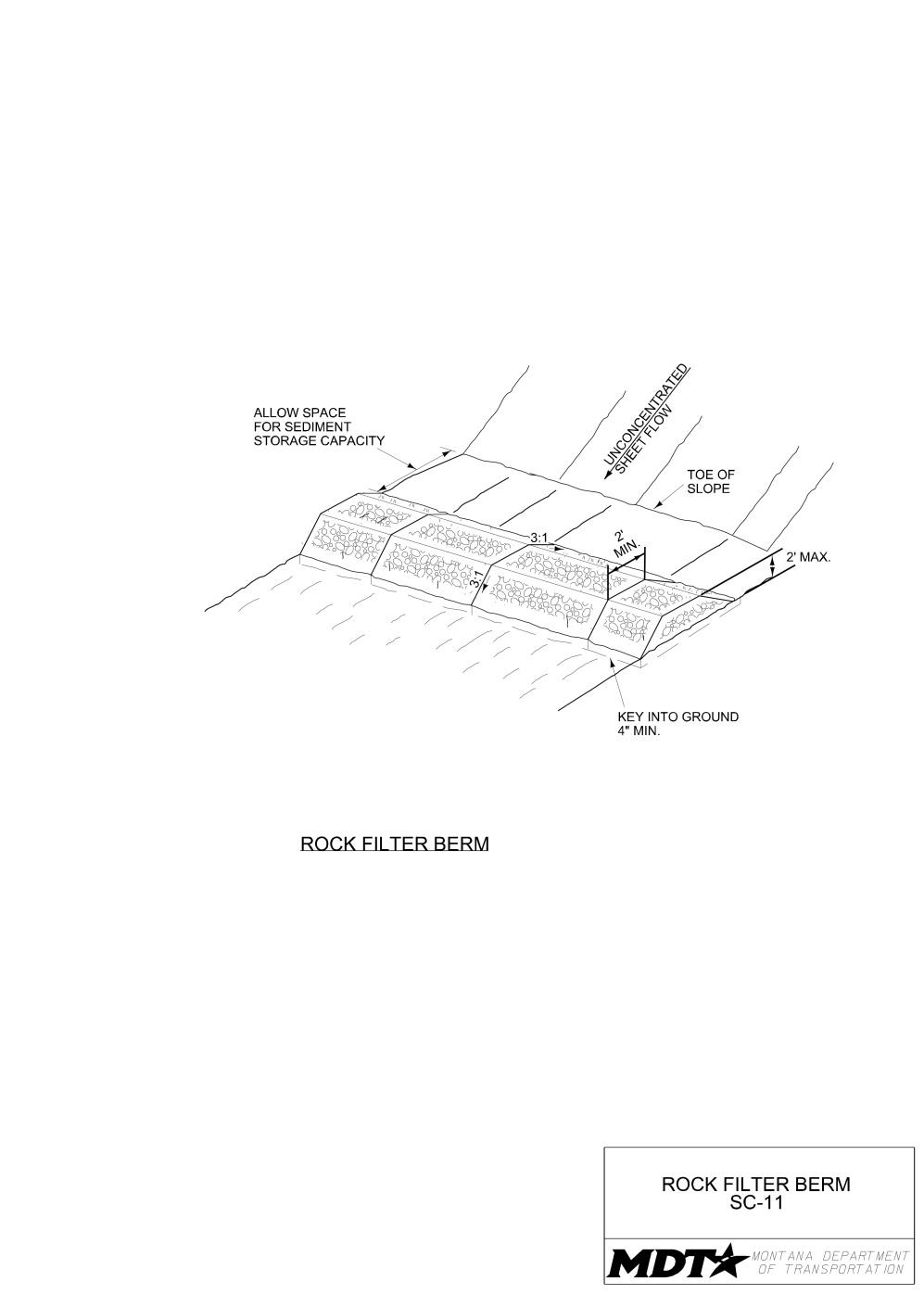
Definition and Purpose
Protection used at storm drain drop and curb inlets and culvert inlets and outlets that are subject to runoff from construction activities. The purpose is to detain sediment-laden runoff and allow sediment to settle/filter out prior to discharge of storm water into storm water drainage systems or watercourses.
AT A GLANCE
Objectives
☐ Construction Site Planning ☐ Temporary Soil Stabilization ☒ Run-on and Runoff Control ☒ Temporary Sediment Control ☐ Snow Management ☐ Good Housekeeping ☐ Waste Management
Applications
☐ Site Perimeter ☒ Inlets and Outlets ☐ Exposed Areas ☐ Sediment Traps/Basins ☐ Slopes ☒ Near Water/Wetlands ☐ Toe of Slopes ☐ Pollution/Material ☐ Ditches Sources ☐ Cut/Fill Transitions
Alternative BMPs to Consider
• Not applicable
Use In Conjunction With
• SC-1 Silt Fence • SC-2 Desilting Basin • SC-3 Sediment Trap • SC-6 Fiber Rolls • SC-7 Compost Socks • SC-9 Sandbag Barrier
Limitations
• Ponding can occur at the inlet with possible shortterm flooding. Use only when ponding will not encroach into highway traffic or onto erodible surfaces and slopes. • Can create obstacles along roadways, particularly in urban areas. • Sediment removal may be difficult in high-flow conditions or if runoff is heavily sediment laden. If high-flow conditions are expected, use other on-site sediment trapping techniques in conjunction with inlet protection. • Frequent maintenance is required.
Source: Tom Gore
Good example of properlyinstalled inlet protection. Rock wattle has a long interface with the curb.
Inlet protection cannot be allowed to become overwhelmed with sediment.
Source: Tom Gore
Effectiveness
• Most effective when appropriate material and method are chosen for the inlet/outlet location and the flow velocity anticipated. • Least effective when not maintained.
Materials
• Refer to SC-6 Fiber Rolls, SC-7 Compost Socks, and SC-9 Sandbag Barrier for materials. Refer to SC-1 Silt Fence for fabric and wire mesh requirements. Use 2inch by 4-inch wood framing with filter fabric at drop inlets. • Additional materials include wire wrapped rock wattles, masonry blocks, 1/2-inch wire mesh, washed 3/4-inch aggregate, straw bales, and prefabricated below inlet grate devices.
Design and Installation
• For drainage areas larger than 1 acre, route runoff to a sediment trapping device designed for larger flows. See SC-2 Desilting Basin and SC-3 Sediment Traps. • Identify existing and/or planned inlets and outlets that have the potential to receive sediment-laden surface runoff. Determine if protection is needed, and which method to use. Paved surfaces will require materials with good surface contact.
Trenched materials are appropriate for unpaved surfaces. • Calculate anticipated flow volumes and velocities to determine method. Straw bale barriers and silt fence are best for flows less than 0.5 cfs. Sandbag barriers can be used for flows greater than 0.5 cfs. • Do not place filter fabric directly underneath the inlet grate since the collected sediment may fall into the drain inlet when the fabric is removed or replaced. • Ensure that ponding will not encroach into roadway traffic. • If working in a MS4, verify applicable ordinances and product requirements. • Wire-wrapped Rock Wattles can be used at drop inlets and curb inlets with paved surfaces, or at drop inlets with unpaved surfaces if trenched. When using around drop inlets: - Butt wattles tightly together with no gaps. - Masonry blocks can be used in conjunction with rock wattles as a secondary sediment control. • Rock Curb Socks are effective at slowing flow velocities and trapping sediment when spaced along gutter and tightly abutted against the curb. This method can be used in conjunction with additional sediment control protection at the drop or curb inlet. The number of socks to use depends on the length of curb/gutter upstream of the inlet. In general, the number to use is as follows.
Length of Curb/Gutter Before Inlet Number of Socks Upstream of Inlet
0 to 5 feet 1 5 to 10 feet 2 Longer than 10 feet 3
• Aggregate may only be used at drop inlets and curb inlets with paved surfaces if used in conjunction with wire mesh and masonry blocks. The aggregate provides an effective filter, while the mesh and blocks keep the aggregate from falling in the inlet. - Use a minimum 3/4-inch washed aggregate and 1/2-inch wire mesh for this application. - Masonry blocks are placed holes on the side, allowing water to flow into the inlet.
Design and Installation
- The wire mesh is placed under the aggregate and folded up and over the masonry block. • Sandbag Barrier may be used at drop inlets and curb inlets with paved or unpaved surfaces. - Install sandbags in a pyramid stacking pattern with alternating joints. - Because sandbags have the potential to rip and discharge sand into the inlet, use this method in areas with minimal construction activity. • Below-inlet Grate Devices, such as witch hats, may be used. Install in accordance with submitted manufacturer’s specifications. • Straw Bale Barriers may be used at drop inlets with unpaved surfaces. - Butt straw bales tightly together with no gaps. - Entrench bales a minimum of 4 inches into the ground and staked in place. • Silt Fence fabric may be used at drop inlets with unpaved surfaces if used in conjunction wire mesh backing and fence posts or wood framing capable of withstanding higher flow velocities. - Use 14 gauge wire mesh as backing for the filter fabric. - Wood framing that consists of 2-inch by 4-inch dimensional lumber that is driven into the ground can be used as the support structure. - Entrench the filter fabric and wire mesh a minimum 12 inches below the ground surface. • Compost Socks may be used at drop inlets, curb inlets, and culvert inlets and outlets that are paved or unpaved and are not located directly upstream from impaired water bodies. - They do not need to be entrenched. - For unpaved surfaces, stake compost socks in place (refer to SC-7 for staking detail) and abut them tightly together with no gaps. - On paved surfaces, compost socks need not be staked. Their weight, when wetted, holds them in place and provides continuous surface contact. Because they are not staked, only use compost socks on paved surfaces with minimal flow. • Fiber Rolls may be used at drop inlets and culvert inlets and outlets that are unpaved. - Abutt fiber rolls at drop inlets tightly together with no gaps, entrench a minimum of 2 inches below the ground surface, and properly staked (refer to SC-6 for staking detail). - At culvert inlet and outlets, entrench fiber rolls a minimum of 2 inches below the ground surface and secure them with stakes. Turn ends of fiber rolls upslope to prevent runoff from flowing around the roll.
Inspection and Maintenance
• Provide regular inspections at the frequency required by the NPDES/MPDES storm water permit to ensure inlet and outlet protection is maintained and functioning properly. If no storm water permit is required for the project, conduct inspections as specified in the contract.
Inspection and Maintenance
• Inspect inlets and outlets after severe storms to check for bypassed material. • Repair washouts or other damage as needed. • Clean the inside of the storm drain inlets as needed to remove sediment and debris. • Inspect fiber rolls, compost socks, silt fence, and sandbag barriers for tears, gashes, or holes. Repair or replace as needed. • Check sandbags for proper arrangement and displacement. • Replace or repair damaged bales as needed. • Make sure stakes are securely driven in the ground and are in good shape. Replace damaged stakes. • Replace or clean any filter fabric when the fabric becomes clogged with sediment. • Remove sediments when depth reaches 1/3 of the barrier height. Incorporate removed sediment into the project or dispose of it in accordance with all laws, rules, and applicable regulations.
Removal
• Remove all inlet/outlet protection devices once adjacent areas have been stabilized, when protection is no longer needed, or upon completion of the work. • Bring the disturbed area to final grade and smooth and compact it. Appropriately stabilize all bare areas around the inlet or outlet. • Clean any remaining sediment around inlets and outlets and clean the inside of storm drain inlets, as they must be free of sediment and debris. • Straw bales, fiber rolls, and compost socks may be scattered when their function as a storm water barrier is completed. • Incorporate removed sediment into the project or dispose of it in accordance with all laws, rules, and applicable regulations.
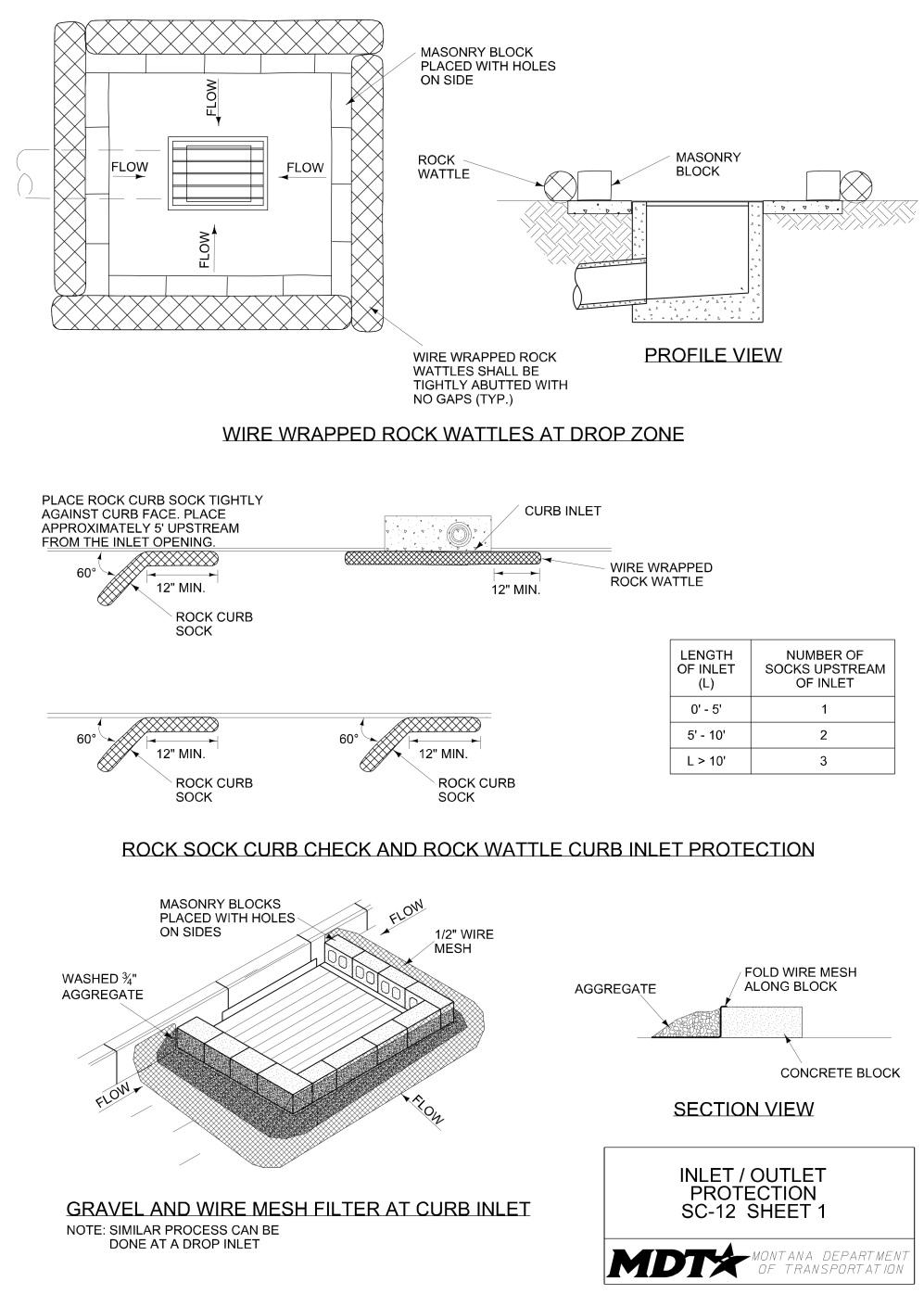
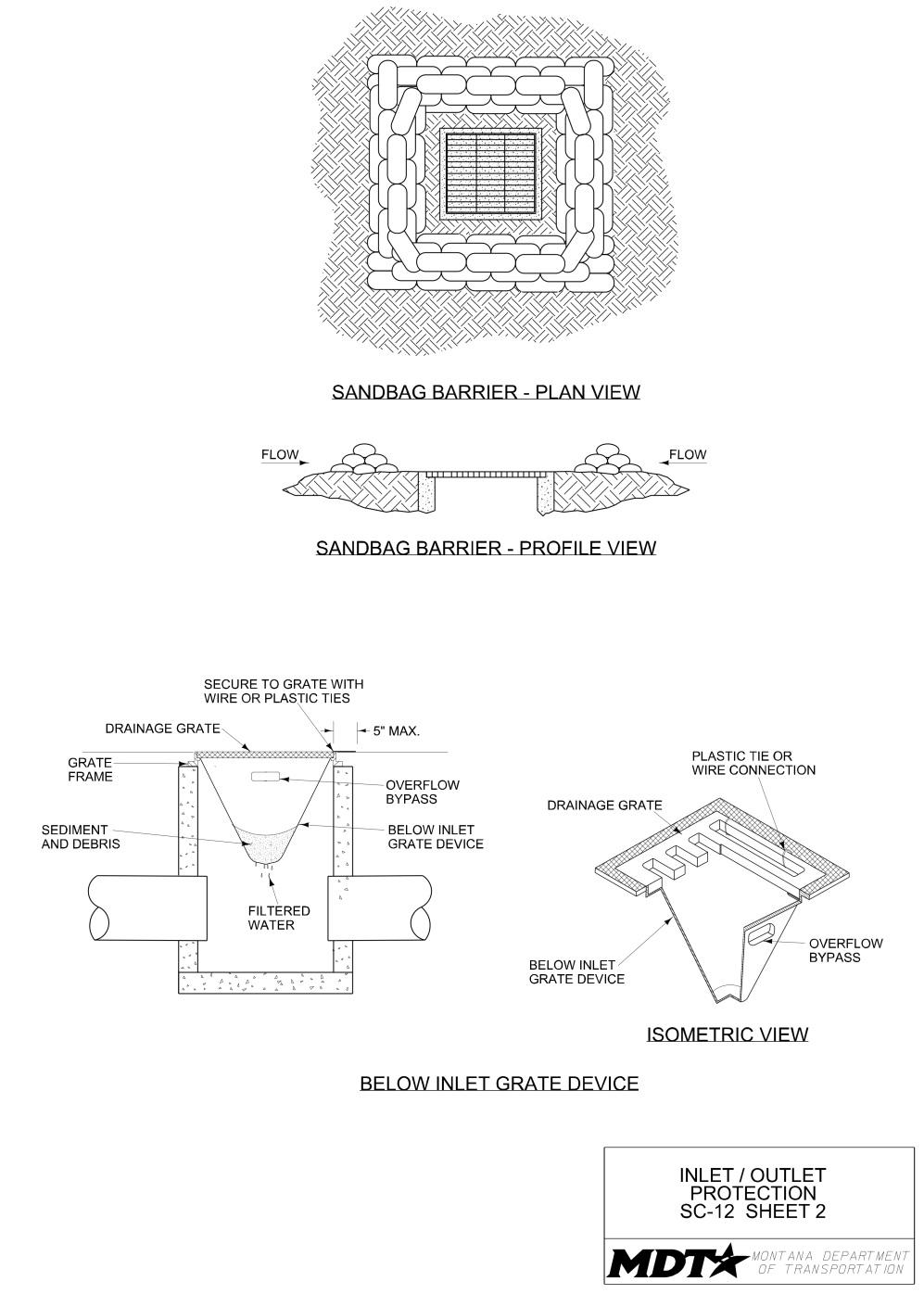
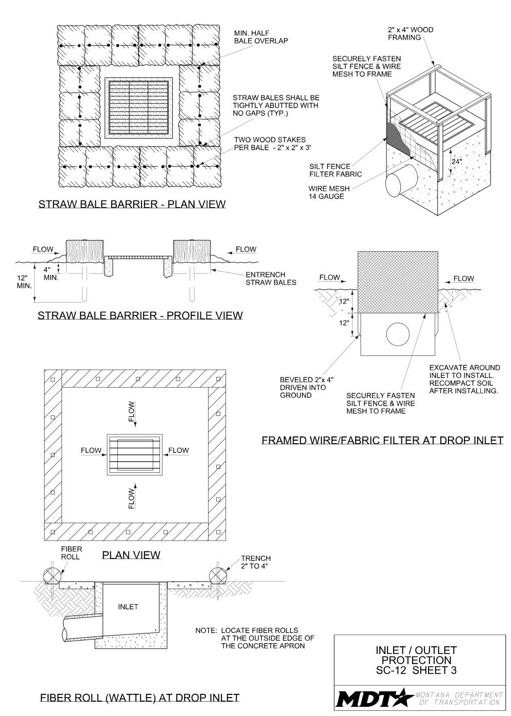
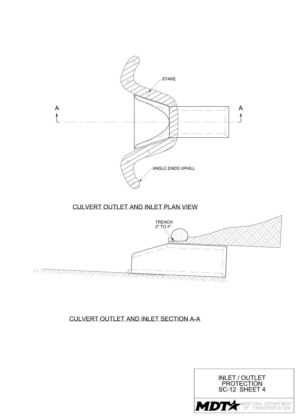
Definition and Purpose
A defined point of entrance/exit to a construction site that is stabilized to reduce the tracking of mud and dirt onto public roads by construction vehicles.
Objectives
☐ Construction Site Planning ☐ Temporary Soil Stabilization ☐ Run-on and Runoff Control ☒ Temporary Sediment Control ☐ Snow Management ☒ Good Housekeeping ☐ Waste Management
AT A GLANCE
Applications
☒ Site Perimeter ☐ Inlets and Outlets ☐ Exposed Areas ☐ Sediment Traps/Basins ☐ Slopes ☐ Near Water/Wetlands ☐ Toe of Slopes ☐ Pollution/Material ☐ Ditches Sources ☐ Cut/Fill Transitions
Alternative BMPs to Consider
• GH-1 Vehicle and Equipment Cleaning
Use In Conjunction With
• CP-1 Scheduling • GH-1 Vehicle and Equipment Cleaning • GH-4 Street Sweeping and Vacuuming • SC-14 Stabilized Construction Roadway • SC-15 Entrance/Outlet Tire Wash
Limitations
• Site conditions will dictate design, location, and number of stabilized access points. • May not remove all soil from vehicle tires; street sweeping and vacuuming may be required.
Source: Tom Gore
Properly-installed features will include an underlayment of geotextile and placement of aggregate. A rumble strip can be added.
Unstabilized construction access can lead to excessive sediment tracking onto adjacent roads.
Source: Tom Gore
Effectiveness
• Most effective when used in combination with tire wash area, rumble pad, and fencing. • Least effective when improperly maintained and allowed to fill with sediment.
Materials
• Construct stabilized construction entrances/exits using material consisting of gravel with 100% passing the 3-inch screen and a maximum of 10% passing the 3/8-inch sieve. • Select construction access stabilization material (e.g., aggregate, asphaltic concrete, concrete) based on longevity, required performance, and site conditions. Do not use asphalt millings for stabilized construction access/roadway.
Design and Installation
• Use stabilized construction accesses where dirt and mud may be tracked onto public roads, adjacent to water bodies, where poor soils are encountered, and where dust may be a problem. • Limit the points of entrance/exit to the construction site through use of fencing. • Limit speed of vehicles to control dust. • Design stabilized entrance/exit to support heaviest vehicles and equipment that will use it. Size the stabilized access pad area to accommodate all vehicles entering/exiting the site. Provide a minimum pad width of 12 feet, and a minimum pad length of 50 feet. Place stabilization material to a minimum thickness of 12 inches. • Install nonwoven, high-strength geotextile fabric between stabilization material and the existing ground surface. • Consider use of constructed/manufactured steel plates with ribs or cattle guard to serve as rumble pad at entrance/exit access points in combination with stabilized access pads. • Properly grade entrances/exits to prevent runoff from leaving the site. Place a mounded berm of material if required to prevent storm water run-on/runoff and/or provide cover for drain pipe. Route storm water runoff to a sediment control device before runoff exits the site. Install drainage pipe to convey flow underneath access pad as needed.
Inspection and Maintenance
• Provide regular inspections at the frequency required by the NPDES/MPDES storm water permit to ensure stabilized construction entrances/exits are maintained and function properly. If no storm water permit is required for the project, conduct inspections as specified in the contract. • Inspect routinely for damage and assess effectiveness of the BMP. Repair/replace if access is clogged with sediment. • Keep all temporary roadway ditches clear. • Maintain stabilized construction entrances to prevent tracking of sediment off of the site. Remove and replace aggregate when voids are filled. • Sweep and remove soil tracked onto paved surfaces.
Removal
• Remove after completion of project.
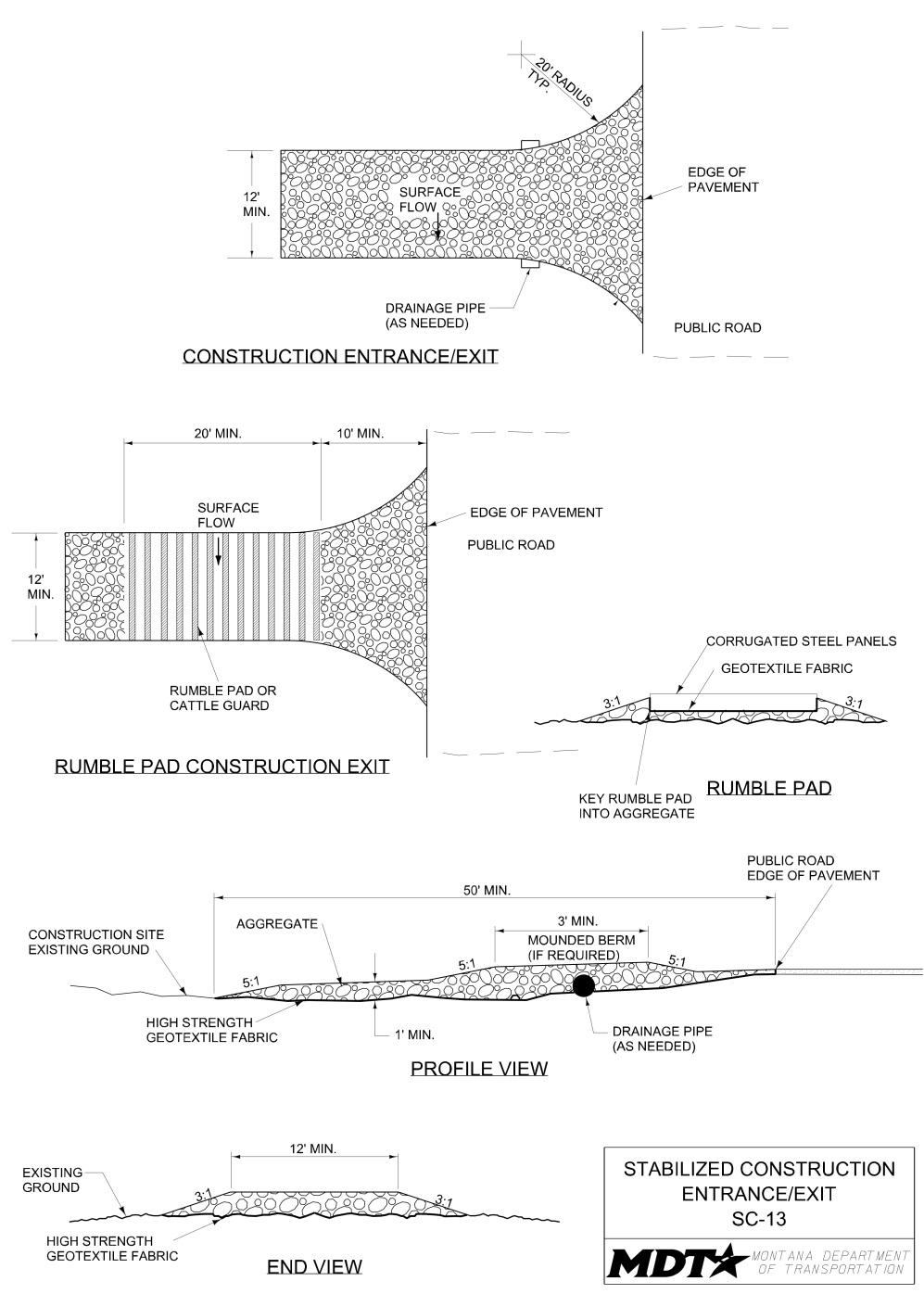
Definition and Purpose
A temporary access road connecting existing public roads to a remote construction area. It is designed for the control of dust and erosion created by vehicular tracking.
Objectives
☐ Construction Site Planning ☐ Temporary Soil Stabilization ☐ Run-on and Runoff Control ☒ Temporary Sediment Control ☐ Snow Management ☒ Good Housekeeping ☐ Waste Management
AT A GLANCE
Applications
☒ Site Perimeter ☐ Inlets and Outlets ☒ Exposed Areas ☐ Sediment Traps/Basins ☐ Slopes ☐ Near Water/Wetlands ☐ Toe of Slopes ☐ Pollution/Material ☐ Ditches Sources ☐ Cut/Fill Transitions
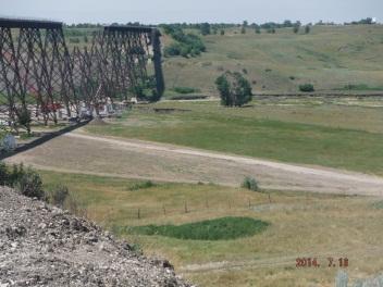
Alternative BMPs to Consider
• Not applicable.
Use In Conjunction With
• CP-1 Scheduling • GH-4 Street Sweeping and Vacuuming • SC-13 Stabilized Construction Entrance/Exit
Source: MDT
Provide a designated access road to control dust and erosion.
Limitations
• Materials will likely need to be removed prior to final project grading and stabilization. • Site conditions will dictate design and need. • May not be appropriate for short-duration projects. • Vehicle speeds must be limited to control dust.
Effectiveness
• Most effective when used in combination with stabilized construction entrance/exit points. • Least effective when improperly maintained.
Materials
• Stabilize roadway using aggregate, asphaltic concrete, or concrete based on longevity, required performance, and site conditions. Do not use AC millings for stabilized construction roadway. • Construct stabilized construction roadways with material consisting of 100% passing the 3-inch screen and a maximum of 10% passing the 3/8-inch sieve. • Coordinate materials with those used for stabilized construction entrance/exit points.
Design and Installation
• Properly grade roadway to prevent runoff from leaving the construction site. Install drainage pipe to convey flow underneath roadway as needed. • Design stabilized roadway to support the heaviest vehicles and equipment that will use it. Provide a minimum roadway width of 12 feet. Place stabilization material to a minimum thickness of 12 inches. • Install nonwoven, high-strength geotextile fabric between stabilization material and the existing ground surface.
Inspection and Maintenance
• Provide regular inspections at the frequency required by the NPDES/MPDES storm water permit to ensure stabilized construction roadways are maintained and function properly. If no storm water permit is required for the project, conduct inspections as specified in the contract. • Inspect routinely for damage and assess the effectiveness of the BMP. Repair as needed. • Keep all temporary roadway ditches clear. • Maintain stabilized construction roadways to prevent tracking of sediment off of the site. Sweep and remove soil tracked onto paved surfaces.
Removal
• When no longer required, remove stabilized construction roadway and re-grade and repair slopes.
Definition and Purpose
A stabilized construction access point to remove sediment from tires and under carriage, and to prevent sediment from being transported onto public roadways.
Objectives
☐ Construction Site Planning ☐ Temporary Soil Stabilization ☐ Run-on and Runoff Control ☒ Temporary Sediment Control ☐ Snow Management ☒ Good Housekeeping ☐ Waste Management
AT A GLANCE
Applications
☒ Site Perimeter ☐ Inlets and Outlets ☐ Exposed Areas ☐ Sediment Traps/Basins ☐ Slopes ☐ Near Water/Wetlands ☐ Toe of Slopes ☐ Pollution/Material ☐ Ditches Sources ☐ Cut/Fill Transitions
Alternative BMPs to Consider
• Not applicable.
Use In Conjunction With
• CP-1 Scheduling • GH-4 Street Sweeping and Vacuuming • SC-13 Stabilized Construction Entrance/Exit • SC-14 Stabilized Construction Roadway
Limitations
• Requires a supply of wash water; disposal options may be limited. • Requires a turnout or doublewide exit in order to keep entering vehicles from driving through the wash area. • No soaps or solvents may be used. • Wash water must be treated with an appropriate control prior to discharge.
Source: Tom Gore
Incorporate tire wash with a stabilized construction entrance and drainage ditch to convey wash runoff.
Effectiveness
• Most effective when used in combination with stabilized construction roadways and stabilized construction entrances/exits. • Least effective when improperly maintained.
Materials
• Use coarse aggregate, greater than 3 inches but smaller than 6 inches.
Design and Installation
• Incorporate with a stabilized construction entrance/exit (see SC-13). • Construct steel gate wash rack on level ground when possible, on a pad of coarse aggregate. Install a liner below the aggregate. • Provide wash racks designed and constructed/manufactured for anticipated traffic loads. • Provide a drainage ditch that will convey the runoff from the wash area to a sediment sump device. Provide a drainage ditch with sufficient grade, width, and depth to carry the wash runoff. Ensure washwater is disposed of in accordance with all laws, rules, and applicable regulations. • Require that all vehicles leaving the site with mud-caked tires and/or undercarriages use the wash facility. • Constructed/manufactured steel-ribbed plates (self-contained steel tire wash) may be used in lieu of rock.
Inspection and Maintenance
• Provide regular inspections at the frequency required by the NPDES/MPDES storm water permit to ensure entrance/outlet tire wash is maintained and functions properly. If no storm water permit is required for the project, conduct inspections as specified in the contract. • Remove accumulated sediment in wash rack and/or sediment sump to maintain system performance. • Inspect routinely for damage and repair as needed.
Removal
• Remove after project completion.
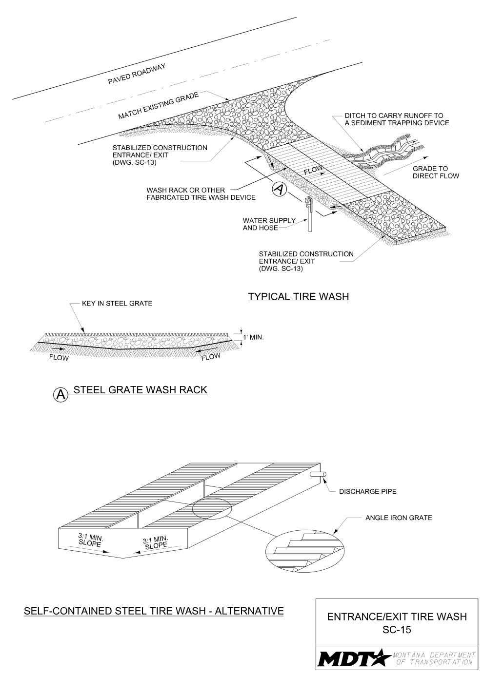
Definition and Purpose
Involves the relocation of snow by transporting, plowing, bulldozing and/or blowing snow to locations where erosion impacts are less likely to occur during melting. This BMP can be used in conjunction with snow fences. It is appropriate when construction projects extend through the winter months and at locations where snow accumulation can be significant.
AT A GLANCE
Objectives
☒ Construction Site Planning ☐ Temporary Soil Stabilization ☒ Run-on and Runoff Control ☒ Temporary Sediment Control ☒ Snow Management ☐ Good Housekeeping ☐ Waste Management
Applications
☒ Site Perimeter ☐ Inlets and Outlets ☐ Exposed Areas ☐ Sediment Traps/Basins ☐ Slopes ☐ Near Water/Wetlands ☐ Toe of Slopes ☐ Pollution/Material ☒ Ditches Sources ☐ Cut/Fill Transitions
Alternative BMPs to Consider
• Not applicable
Use In Conjunction With
• CP-1 Scheduling • SM-2 Snow Accumulation Management
Limitations
• This BMP may not be appropriate in areas with little snow accumulation and where access is limited.
Effectiveness
• Most effective when a snow management plan is in place, stabilized snow storage areas are identified, and appropriate controls are installed before the first snowfall.
Source: Tom Gore
Utilize equipment to move snow to less erosion-sensitive areas.
Place snow in areas where snowmelt will have less of an impact.
Source: Tom Gore
Materials
• Not applicable.
Design and Installation
• For projects with NPDES/MDPES coverage, account for snow management in the project SWPPP if the project will extend into or through winter months. • Utilize snow blowers, snowplows, or other equipment to remove snow or move snow to less erosion-sensitive areas with proper drainage. • Modify existing snowplow operations so snow is not piled in erosion-sensitive areas. • Remove heavy snow accumulation from around temporary structures such as culverts to minimize ice jamming and structure failure during freeze-thaw cycles. • Place snow in areas where soil/cover is temporarily or permanently stabilized and where snowmelt will have a less significant impact. Ensure appropriate controls are in place to handle snow-melt runoff.
Inspection and Maintenance
• Provide regular inspections at the frequency required by the NPDES/MPDES storm water permit to ensure proper snow management measures are being followed and implemented. If no storm water permit is required for the project, conduct inspections as specified in the contract. • Remove or move snow as needed to reduce melt impacts. • Inspect snow placement areas during the thaw cycle.
Removal
• Remove or move snow as needed to reduce melt impacts.
Definition and Purpose
Involves the installation of snow barriers to reduce the amount of erosion on disturbed areas. Temporary snow barriers are most commonly constructed from synthetic materials; however, boards, hay bales, rocks, and other similar materials can be used. ☐ Construction Site Planning ☒ Temporary Soil Stabilization ☐ Run-on and Runoff Control ☐ Temporary Sediment Control ☒ Snow Management ☐ Good Housekeeping ☐ Waste Management
Objectives
AT A GLANCE
Applications
☒ Site Perimeter ☐ Inlets and Outlets ☒ Exposed Areas ☐ Sediment Traps/Basins ☒ Slopes ☐ Near Water/Wetlands ☐ Toe of Slopes ☐ Pollution/Material ☐ Ditches Sources ☐ Cut/Fill Transitions
Alternative BMPs to Consider
• Not applicable
Use In Conjunction With
• SM-1 Snow Management
Limitations
• Snow fences are difficult to install on steep slopes and rocky surfaces. • Snow fences may not be cost effective when large areas need to be protected from snow accumulation. • Removal at the end of the project is labor-intensive.
Effectiveness
• Most effective when correctly placed in a direction that is perpendicular to the wind direction.
Materials
• Provide a prefabricated commercial snow fence made of woven polyethylene and ultraviolet resistant material with a porosity of 40% to 60%. • Boards, hay bales, rocks, and other similar materials can also be used, where applicable.
Design and Installation
• Install snow barriers adjacent to disturbed areas, perpendicular to the prevailing wind direction, and upwind of disturbance area. • Fences in moderate snow areas should be 4 to 6 feet in height. • Space fence posts no more than 8 feet apart. • The bottom gap between the fence and the ground should be 10% to 15% of the fence height; however, in rough terrain or snow covered areas the bottom gap should be higher. • Two or more parallel rows of snow fence may be used in areas of heavy snow accumulation or high wind conditions. • When practical, place fences at a distance of 15 to 20 times the fence height from the area to be protected. • Secure fencing to approved posts.
Inspection and Maintenance
• Provide regular inspections at the frequency required by the NPDES/MPDES storm water permit. If no storm water permit is required for the project, conduct inspections as specified in the contract. • Inspect snow barrier materials and installation throughout the winter to make sure they are functioning properly. • Remove snow accumulation from fencing once levels have reached the bottom of the fence.
Removal
• Remove all snow barriers when the areas to be protected have been stabilized.
Definition and Purpose
Objectives
Involves the use of oversized culverts, dual ☐ Construction Site Planning culverts, elevated culvert outlets, and heat ☐ Temporary Soil Stabilization trace to reduce the impacts of freezing ☒ Run-on and Runoff Control weather on culvert effectiveness. Snow and ice ☐ Temporary Sediment Control accumulations in structures, such as ditches ☒ Snow Managementand culverts, can lead to plugging and subsequently to significant water flows across ☐ Good Housekeeping disturbed areas causing erosion. Frozen ☐ Waste Management culverts can cause water to flow over roadways, resulting in destabilization. Ice blockage in channels can increase water levels in the channels causing flooding and potentially resulting in damage.
AT A GLANCE
Applications
☐ Site Perimeter ☒ Inlets and Outlets ☐ Exposed Areas ☐ Sediment Traps/Basins ☐ Slopes ☐ Near Water/Wetlands ☐ Toe of Slopes ☐ Pollution/Material ☒ Ditches Sources ☐ Cut/Fill Transitions
Alternative BMPs to Consider
• Not applicable
Use In Conjunction With
• SM-1 Snow Management
Limitations
• Areas with limited access and space to install oversized and/or dual hydraulic structures. • Elevated culvert outlets in streams should be avoided if fish migration is a concern. • Heat trace may not be appropriate for remote areas with limited access to electricity.
Effectiveness
• Most effective when culverts are sized and installed properly.
Materials
• Use heat trace in culverts to prevent freezing.
Design and Installation
• Install oversized culverts to allow for some freezing. • Install dual culverts with one culvert raised higher in elevation than the other culvert. This will allow water passage through the upper culvert if the lower culvert freezes. • A vertical drop of approximately 2 feet at a culvert outlet may reduce water freezing within the culvert. Consider other requirements (e.g., aquatic organisim passage) if a vertical drop from the culvert is provided. • Install channel freeze protective measures (heat trace) as shown in drawing SM-3. • Complete all electrical work using a licensed electrician and in accordance with the national electrical codes.
Inspection and Maintenance
• Inspect temporary structures during freezing conditions and prior to spring thaw to assure that they are properly functioning.
Removal
• Disconnect and remove any electrical components when no longer required for freeze reduction.

Definition and Purpose
Procedures and practices used to minimize or eliminate the discharge of pollutants from vehicle and equipment cleaning operations to storm drain systems or watercourses, and to reduce or eliminate spread of noxious weeds and invasive plant species from the project site. ☐ Construction Site Planning ☐ Temporary Soil Stabilization ☐ Run-on and Runoff Control ☐ Temporary Sediment Control ☐ Snow Management ☒ Good Housekeeping ☒ Waste Management
Objectives
AT A GLANCE
Applications
☐ Site Perimeter ☐ Inlets and Outlets ☐ Exposed Areas ☐ Sediment Traps/Basins ☐ Slopes ☐ Near Water/Wetlands ☐ Toe of Slopes ☒ Pollution/Material ☐ Ditches Sources ☐ Cut/Fill Transitions
Alternative BMPs to Consider
• Not applicable
Use In Conjunction With
• GH-8 Spill Prevention and Control • WM-1 Solid Waste Management • WM-2 Hazardous Waste Management • WM-3 Contaminated Soil Management • WM-6 Liquid Waste Management
Limitations
• On-site vehicle and equipment washing is discouraged. • Cleaning vehicles and equipment generates liquid, semi-solid and solid wastes, which must be contained on-site and/or treated to prevent pollution. • Construction of enclosed wash area and wash water disposal can be costly.
Effectiveness
• Most effective when proper containment and disposal plans are in place to ensure the effectiveness of vehicle and equipment washing on site. Off-site vehicle and equipment cleaning is encouraged.
Materials
• Not applicable.
Design and Installation
• On-site vehicle and equipment washing is discouraged. • All vehicles and equipment that regularly enter and leave the construction site must be cleaned off site. Clean all equipment and vehicles prior to their transport into the project area. • Do not allow equipment or vehicles with visible dirt or plant parts into the project area until they are cleaned. • If vehicle and equipment washing and cleaning must occur on site, designate on-site stations on impervious surfaces, if possible, and 50 feet away from storm drain inlets, drainage facilities, or watercourses. • If the operation cannot be located within a structure or building equipped with appropriate disposal facilities, provide an outside cleaning area meeting the following characteristics. - Located 50 feet away from storm drain inlets, drainage facilities, or watercourses. - Paved with concrete or asphalt and bermed with an impermeable material to contain wash waters and to prevent run-on and runoff. - Configured with a sump to allow collection and disposal of wash water. - Used only when necessary. • Contain vehicle and equipment wash water for percolation or evaporative drying away from storm drain inlets, drainage facilities, open ditches, and/or watercourses. Do not discharge wash water within the right-of-way, to storm drains, or watercourses. • Do not cleaning vehicles and equipment with soap, detergents, solvents, or steam on the project site unless the resulting wastes are fully contained and disposed of in accordance with all laws, rules, and applicable regulations. • The use of diesel fuel for vehicle and equipment cleaning is prohibited. • When cleaning vehicles/equipment with water: - Use as little water as possible. High-pressure sprayers may use less water than a hose, and should be considered. - Use positive shutoff valve to minimize water usage. • Provide facility wash racks which discharge to a sanitary sewer, recycle system, or other appropriate discharge system and which do not discharge to storm drains or watercourses.
Inspection and Maintenance
• Provide regular inspections of vehicle cleaning areas at the frequency required by the NPDES/MPDES storm water permit to ensure proper measures are being followed. If no storm water permit is required for the project, conduct inspections as specified in the contract. • Inspect sump regularly and remove liquids and sediment as needed to ensure intended use and function is maintained.
Removal
• Remove the vehicle and equipment cleaning station from the construction site following project completion. • All wash water must be disposed of in accordance with all laws, rules, and applicable regulations.
Definition and Purpose
Vehicle and equipment fueling procedures and practices to minimize or eliminate the discharge of fuel spills and leaks into the storm drain system or to watercourses. ☐ Construction Site Planning ☐ Temporary Soil Stabilization ☐ Run-on and Runoff Control ☐ Temporary Sediment Control ☐ Snow Management ☒ Good Housekeeping ☒ Waste Management
Objectives
AT A GLANCE
Applications
☐ Site Perimeter ☐ Inlets and Outlets ☐ Exposed Areas ☐ Sediment Traps/Basins ☐ Slopes ☐ Near Water/Wetlands ☐ Toe of Slopes ☒ Pollution/Material ☐ Ditches Sources ☐ Cut/Fill Transitions
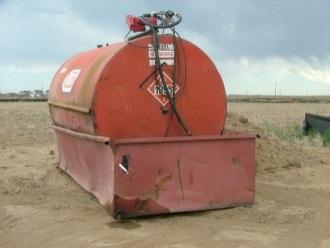
Alternative BMPs to Consider
• Not applicable
Use In Conjunction With
• GH-8 Spill Prevention and Control • WM-3 Contaminated Soil Management • WM-6 Liquid Waste Management
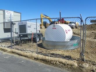
Source: Tom Gore
Check fuel containment for spills and leaks.
Fuel should be properly stored in leak-proof containers.
Limitations
• Only use on-site vehicle and equipment fueling when it is impractical to send vehicles and equipment off-site. • Some permit requirements may dictate whether on-site fueling is allowed.
Source: Tom Gore
Effectiveness
• Most effective when fueling areas are located away from downstream drainage facilities and watercourses, when fueling areas are properly contained, and when proper fueling and waste management guidelines are understood and followed by project personnel.
Materials
• Provide absorbent spill clean-up materials and spill kits in fueling areas and on fueling trucks and dispose of used materials in accordance with all laws, rules, and applicable regulations.
Design and Installation
• When fueling must occur on site, select and designate an area to be used. • Protect dedicated fueling areas from storm water run-on and runoff, and locate at least 50 feet from downstream drainage facilities and watercourses. • Fueling must be performed on level-grade areas. • Make absorbent spill clean-up materials and spill kits available and appropriately identified in fueling areas and on fueling trucks. • Use absorbent materials on small spills. Do not hose down or bury spills. Remove spent absorbent material promptly and dispose of all used materials in accordance with all laws, rules, and applicable regulations. • Use drip pans or absorbent pads during vehicle and equipment fueling. • In vehicle and equipment fueling areas, use only nozzles equipped with an automatic shut-off. Do not leave fueling operations unattended. • Size the containment area to provide sufficient freeboard. • Protect fueling areas with impermeable berms and/or dikes to prevent run-on, runoff, and to contain spills. • Do not top off fuel tanks. • Comply with all federal, state, tribal, and local requirements for any stationary above-ground storage tanks. • Whenever practical, transport equipment to the designated fueling area rather than using mobile fueling operations.
Inspection and Maintenance
• Provide regular inspections of fueling areas and storage tanks at the frequency required by the NPDES/MPDES storm water permit to ensure proper measures are being followed. If no storm water permit is required for the project, conduct inspections as specified in the contract. • Inspect vehicles and equipment daily for leaks. • Repair leaks immediately, or remove problem vehicles/equipment from the project site. • Keep an ample supply of spill clean-up material on the site. • Immediately clean up spills and dispose of contaminated soil and clean-up materials in accordance with all laws, rules, and applicable regulations.
Removal
• Remove the fueling area, berms/dikes, and fueling area equipment when no longer needed or at the completion of the work.
Definition and Purpose
Vehicle and equipment maintenance procedures and practices to minimize or eliminate the discharge of pollutants to the storm drain system or to watercourses from vehicle and equipment maintenance procedures. This BMP promotes the proper disposal of equipment and other vehicle maintenance waste or debris. ☐ Construction Site Planning ☐ Temporary Soil Stabilization ☐ Run-on and Runoff Control ☐ Temporary Sediment Control ☐ Snow Management ☒ Good Housekeeping ☒ Waste Management
Objectives
AT A GLANCE
Applications
☐ Site Perimeter ☐ Inlets and Outlets ☐ Exposed Areas ☐ Sediment Traps/Basins ☐ Slopes ☐ Near Water/Wetlands ☐ Toe of Slopes ☒ Pollution/Material ☐ Ditches Sources ☐ Cut/Fill Transitions
Alternative BMPs to Consider
• Not applicable
Use In Conjunction With
• GH-8 Spill Prevention and Control • WM-2 Hazardous Waste Management • WM-3 Contaminated Soil Management
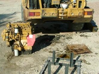
Source: Tom Gore
Use drip pans or spill pads during vehicle maintenance.
Minimize vehicle leaks to the soil surface.
Limitations
• Local codes and ordinances regarding the disposal of fluids and consumable goods, and the on-site maintenance of equipment.
Source: Tom Gore
Effectiveness
• Most effective when maintenance areas are designated and located away from downstream drainage facilities and watercourses, when fluid containers are properly stored, and when proper maintenance guidelines are understood and followed by project personnel.
Materials
• Do not use diesel fuel as a cleaning agent or as a release agent for any paving equipment or operations. Use a commercially-manufactured release agent. • Make drip pans, absorbent pads, spill clean-up materials, and spill kits available in maintenance areas. • Provide readily available MSDS for all materials used or stored on the project site.
Design and Installation
• Use off-site maintenance facilities whenever practical. • When vehicle and equipment maintenance must occur on site, select and designate an area to be used. • Protect dedicated maintenance areas from storm water run-on and runoff, and locate at least 50 feet from downstream drainage facilities and watercourses. • For long-term projects, consider using portable tents or covers over maintenance areas. • Use drip pans or absorbent pads during vehicle and equipment maintenance work that involves fluids. • All fueling trucks and fueling areas are required to have spill kits and/or use other spill protection devices. • Place drip pans or plastic sheeting under all vehicles and equipment located on docks, barges, or other structures over water bodies when the vehicle or equipment is planned to be idle for more than one hour. • Make absorbent spill clean-up materials available in maintenance areas and dispose of waste materials in accordance with all laws, rules, and applicable regulations. • Use non-toxic substances to coat asphalt transport trucks and asphalt-spreading equipment. Dispose of used oils, fluids, lubricants, and spill clean-up materials in accordance with all laws, rules, and applicable regulations. • Do not dump fuels and lubricants onto the ground. • Do not place used oil in a dumpster or pour into a storm drain or watercourse. • Recycle or dispose of used batteries in accordance with all laws, rules, and applicable regulations. • Do not bury used tires. • Provide spill containment dikes or secondary containment around stored oil and chemical drums.
Inspection and Maintenance
• Provide regular inspections of vehicle and equipment maintenance areas at the frequency required by the NPDES/MPDES storm water permit to ensure proper measures are being followed. If no storm water permit is required for the project, conduct inspections as specified in the contract. • Inspect vehicles and equipment on each day of use. • Repair leaks immediately or remove the problem vehicle/equipment from the project site. • Inspect equipment for damaged hoses and leaky gaskets routinely. Repair or replace as needed. • Inspect waste fluid containers for leaks and maintain them in a leak-proof condition. • Keep an ample supply of spill clean-up material on the site.
Removal
• Remove the vehicle and equipment maintenance station when no longer needed or at the completion of the work. • Dispose of all vehicle and equipment fluids in accordance with all laws, rules, and applicable regulations.
Definition and Purpose
Practices to remove tracked sediment from the project site onto public or private paved roads. The purpose is to prevent sediment from entering a storm drain or watercourse. ☐ Construction Site Planning ☐ Temporary Soil Stabilization ☐ Run-on and Runoff Control ☒ Temporary Sediment Control ☐ Snow Management ☒ Good Housekeeping ☒ Waste Management
Objectives
AT A GLANCE
Applications
☒ Site Perimeter ☐ Inlets and Outlets ☐ Exposed Areas ☐ Sediment Traps/Basins ☐ Slopes ☐ Near Water/Wetlands ☐ Toe of Slopes ☒ Pollution/Material ☐ Ditches Sources ☐ Cut/Fill Transitions
Alternative BMPs to Consider
• Not applicable
Use In Conjunction With
• SC-13 Stabilized Construction Entrance/Exit • SC-14 Stabilized Construction Roadway
Limitations
• Some jurisdictions only allow vacuum sweepers. • Sweeping and vacuuming may not be effective when soil is wet, sticky, compacted, or muddy.
Effectiveness
• Most effective when sweeping is conducted at the end of each work day and during dry conditions.
Source: Tom Gore
Sweep and/or vacuum visible sediment tracking by the end of the same work day.
Inspect ingress/egress access points daily for tracking from site.
Source: Tom Gore
Materials
• Not applicable.
Design and Installation
• If not mixed with debris or trash, consider incorporating the removed sediment back into the project. • Sweepers must meet all federal, state, tribal, and local air quality regulations.
Inspection and Maintenance
• Sweep and/or vacuum visible sediment tracking by the end of the same work day, or by the end of the next work day if track-out occurred on a non-work day. • Inspect ingress/egress access points daily and sweep tracked sediment as needed. • Be careful not to sweep up any unknown substance or any object that may be potentially hazardous. • Adjust brooms frequently to maintain proper contact with the ground and maximize efficiency of sweeping operations. • After sweeping is finished, dispose of waste materials in accordance with all laws, rules, and applicable regulations.
Removal
• Plan for proper disposal of wastes at an approved dumpsite or consider incorporating sediment back into project site if free of debris and trash.
Definition and Purpose
Objectives
Procedures and practices for the proper ☐ Construction Site Planning handling, delivery, and storage of all ☐ Temporary Soil Stabilization construction materials in a manner that ☐ Run-on and Runoff Control minimizes or eliminates the discharge of these ☐ Temporary Sediment Control materials to a storm drain system or to ☐ Snow Managementwatercourses. These procedures are implemented when the following materials are ☒ Good Housekeeping used or prepared on site: soil; pesticides and ☒ Waste Management herbicides; fertilizers; detergents; plaster; asphalt and concrete; petroleum products such as fuel, oil, lubricants, and grease; soil stabilizers and binders; hazardous chemicals such as acids, lime, glue, adhesives, paints, solvents, and curing compounds; and other materials that may be harmful to the environment.
AT A GLANCE
Applications
☐ Site Perimeter ☐ Inlets and Outlets ☐ Exposed Areas ☐ Sediment Traps/Basins ☐ Slopes ☐ Near Water/Wetlands ☐ Toe of Slopes ☒ Pollution/Material ☐ Ditches Sources ☐ Cut/Fill Transitions
Alternative BMPs to Consider
• Not applicable
Use In Conjunction With
• GH-6 Material Use • GH-8 Spill Prevention and Control • WM-2 Hazardous Waste Management
Limitations
• Space limitation may preclude indoor storage. • Storage sheds must meet building and fire code requirements.
Effectiveness
• Most effective when materials are properly contained and stored away from drainage facilities and watercourse, and when proper storage guidelines are understood and followed by project personnel.
Source: Tom Gore
Store liquids and petroleum products in approved containers and drums. Place them in temporary containment areas for storage.
When available, store materials indoors within existing structures or sheds.
Source: Tom Gore
Materials
• Provide readily available MSDS for all materials used or stored on the project site.
Design and Installation
• Train project personnel on proper material delivery and storage practices.
Material Storage Areas and Practices
• When available, store materials indoors within existing structures or sheds. • Storage sheds must meet building and fire code requirements. • Locate chemical and material storage areas away from low areas, drainages and stream banks, and outside the 100-year flood level. • Locate temporary storage areas away from vehicular traffic. • Store MSDS in a central location, which is accessible at all times and inform all personnel of that location. • Store liquids and petroleum products in approved containers and drums and place them in temporary containment areas for storage. Do not overfill drums. • Complete storage, preparation, and mixing within temporary containment facilities.
Provide each temporary containment facility with a spill containment volume equal to 1.5 times the volume of all containers therein and which is impervious to the materials contained therein for a minimum contact time of 72 hours. • Provide sufficient separation between stored containers to allow for spill clean up and emergency response access. • Do not store incompatible materials, such as chlorine and ammonia, in the same temporary containment facility. • To provide protection from wind and rain, cover temporary containment facilities during non-working days and prior to rain events. • Maintain temporary containment facilities in a condition which is free of accumulated rainwater and spills. • Store materials in their original containers and maintain the original product labels in place and in a legible condition. Replace damaged or otherwise illegible labels immediately. • Store bagged and boxed materials on pallets and do not allowed them to accumulate on the ground. • To provide protection from wind and rain, cover bagged and boxed materials during non-working days and prior to rain events. • Protect stockpiles in accordance with GH-7 Stockpile Management. • Minimize the material inventory stored on-site (e.g., only a few days’ supply). • Have proper storage instructions posted at all times in an open and conspicuous location. • Keep hazardous chemicals well labeled and in their original containers. • Keep ample supply of appropriate spill clean-up material near storage areas. • Also see WM-2 Hazardous Waste Management for storing of hazardous materials.
Material Delivery Practices
• Keep an accurate, up-to-date inventory of material delivered and stored on-site. • Have employees trained in emergency spill clean-up procedures present when dangerous materials or liquid chemicals are unloaded.
Design and Installation Spill Clean-up
• Contain and clean-up any spill immediately. • If significant residual materials remain on the ground after construction is complete, remove and dispose of any hazardous materials or contaminated soil in accordance with all laws, rules, and applicable regulations. • See GH-8 Spill Prevention and Control for spills of chemicals and/or hazardous materials.
Inspection and Maintenance
• Provide regular inspections of storage areas at the frequency required by the
NPDES/MPDES storm water permit to ensure proper measures are being followed.
If no storm water permit is required for the project, conduct inspections as specified in the contract. • Inspect containers and storage areas for spills and damage. • Inspect storage areas before and after rainfall events. • Maintain storage areas to prevent rainfall and runoff from coming in contact with chemicals or materials. • Keep storage areas clean, well-organized, and equipped with ample clean-up supplies as appropriate for the materials being stored. • Repaire or replace perimeter controls, containment structures, covers, and liners as needed to maintain proper function. • Clean areas where materials have been removed to insure that no dust or spillage remains to be washed into storm water.
Removal
• Remove all construction materials from the project site upon completion of the work.
Definition and Purpose
Objectives
Procedures and practices for use of ☐ Construction Site Planning construction material in a manner that ☐ Temporary Soil Stabilization minimizes or eliminates the discharge of these ☐ Run-on and Runoff Control materials to the storm drain system or to ☐ Temporary Sediment Control watercourses. These measures ensure the ☐ Snow Managementproper use of materials such as pesticides, herbicides, and fertilizers; detergent and ☒ Good Housekeeping cleaners; petroleum products such as fuel, oil, ☒ Waste Management and grease; asphalt and concrete compounds; plaster; hazardous materials; and any other materials that may pose a threat to environmental and human health.
AT A GLANCE
Applications
☐ Site Perimeter ☐ Inlets and Outlets ☐ Exposed Areas ☐ Sediment Traps/Basins ☐ Slopes ☐ Near Water/Wetlands ☐ Toe of Slopes ☒ Pollution/Material ☐ Ditches Sources ☐ Cut/Fill Transitions
Alternative BMPs to Consider
• Not applicable
Use In Conjunction With
• GH-5 Material Delivery and Storage • GH-8 Spill Prevention and Control
Limitations
• Safer alternative building and construction products may not be available or suitable in every instance.
Effectiveness
• Most effective when proper material handling guidelines are understood and followed by project personnel.
Materials
• Provide readily available MSDS for all materials used or stored on the project site. • Provide absorbent spill clean-up materials and spill kits and dispose of used materials in accordance with all laws, rules, and applicable regulations.
Design and Installation
• Store MSDS in a central location, which is accessible at all times, and inform all personnel of that location. • Latex paint and paint cans, used brushes, rags, absorbent materials, and drop cloths, when thoroughly dry and are no longer hazardous, may be disposed of with other construction debris. • Do not remove the original product label; it contains important safety and disposal information. Use the entire product before disposing of the container. • Mix paint indoors or in a containment area. Do not clean paint brushes or rinse paint containers into a street, gutter, storm drain, or watercourse. Dispose of any paint thinners, residue, and sludge(s) that cannot be recycled in accordance with all laws, rules, and applicable regulations. • For water-based paint, clean brushes to the extent practical and rinse to a drain leading to a sanitary sewer where permitted, or into a concrete washout pit or temporary sediment trap. For oil-based paints, clean brushes to the extent practical, and filter and reuse thinners and solvents. • Use recycled and less hazardous products when practical. Recycle residual paints, solvents, non-treated lumber, and other materials. • Use materials only where and when needed to complete the construction activity. • Use safer alternative materials as much as possible. Reduce or eliminate use of hazardous materials on-site when practical. • Do not over-apply fertilizers and pesticides. Prepare only the amount needed.
Strictly follow the recommended usage instructions. Apply surface dressings in smaller applications, as opposed to large applications, to allow time for it to work in and to avoid excess materials being carried off-site by runoff. • Provide a licensed applicator for the application of herbicides and pesticides. • Maintain logs for all pesticides and herbicides applied, including brand name, formulation, EPA registration number, amount and date applied, exact location of application, size of area treated, vehicle calibration, and name, address, and certification number of applicator. • Keep an ample supply of spill clean-up material near use areas. Train employees in spill clean-up procedures. • Avoid exposing applied materials to rainfall and runoff unless sufficient time has been allowed for them to dry. • Comply with all pertinent local, tribal, state and federal regulations.
Inspection and Maintenance
• Provide regular inspections at the frequency required by the NPDES/MPDES storm water permit to ensure proper measures are being followed. If no storm water permit is required for the project, conduct inspections as specified in the contract. • Maintain an ample supply of clean-up materials at all designated maintenance areas where leaks and spills are likely to occur. • Spot check project personnel monthly throughout the job to ensure appropriate practices are being employed.
Inspection and Maintenance
• Check material use areas regularly for non-labeled materials and spills. • Inspect perimeter controls, containment structures, covers, and liners regularly for spills or damage and repaired or replaced as needed to maintain proper function.
Removal
• Remove all material storage facilities upon the completion of the work. • Ensure hazardous materials are disposed of in accordance with all laws, rules, and applicable regulations.
Definition and Purpose
Procedures and practices to reduce or eliminate pollution of storm water from stockpiles of soil and paving materials such as PCCP rubble, asphalt concrete, asphalt concrete rubble, aggregate base, aggregate sub-base or pre-mixed aggregate, and asphalt binder (cold mix asphalt). ☒ Construction Site Planning ☐ Temporary Soil Stabilization ☐ Run-on and Runoff Control ☒ Temporary Sediment Control ☐ Snow Management ☒ Good Housekeeping ☒ Waste Management
AT A GLANCE
Objectives
Applications
☒ Site Perimeter ☐ Inlets and Outlets ☐ Exposed Areas ☐ Sediment Traps/Basins ☐ Slopes ☐ Near Water/Wetlands ☐ Toe of Slopes ☒ Pollution/Material ☐ Ditches Sources ☐ Cut/Fill Transitions
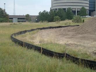
Alternative BMPs to Consider
• Not applicable
Use In Conjunction With
• SS-5 Soil Binders • SS-8 Wind Erosion Control • SC-1 Silt Fence • SC-6 Fiber Rolls • SC-7 Compost Socks • SC-9 Sandbag Barrier • WM-3 Contaminated Soil Management
Limitations
• Appropriate procedures for specific materials used may need to be adjusted to comply with federal, state, tribal, and local regulations.
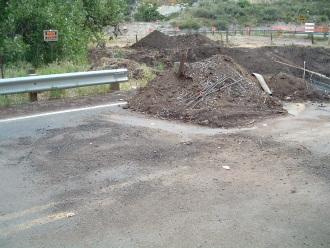
Source: Tom Gore
Protect stockpiles from storm water run-on using a temporary perimeter sediment barrier.
Stockpiles should be properly contained to reduce pollution of storm water.
Source: Tom Gore
Effectiveness
• Most effective when stockpiles are located away from concentrated flows of storm water, drainage courses, and inlets, and when properly protected with perimeter sediment barriers and covered.
Materials
• Not applicable.
Design and Installation
• Protection of stockpiles is a year-round requirement. • Locate stockpiles a minimum of 50 feet away from concentrated flows of storm water, drainage courses, and inlets. • Protect all stockpiles from storm water run-on using a temporary perimeter sediment barrier such as berms, dikes, silt fences, compost socks, or sandbag barriers. • Cover or protect with soil stabilization measures if rain is predicted. • Implement wind erosion control practices as appropriate on all stockpiled material.
For specific information, see SS-8, Wind Erosion Control. • Manage stockpiles of contaminated soil in accordance with WM-3 Contaminated
Soil Management. • Place all bagged materials on pallets and under cover. • Comply with local jurisdiction air quality requirements.
Protection of Non-active Stockpiles
• Protect non-active stockpiles as follows. - Soil stockpiles • Protect with temporary perimeter sediment barriers. • Keep stockpiles covered or protected with soil stabilization measures to avoid direct contact with precipitation and to minimize sediment discharge. • Contain and securely protect from wind, as appropriate. - Stockpiles of PCCP rubble, asphalt concrete, asphalt concrete rubble, aggregate base or sub-base. • Protect stockpiles with temporary perimeter sediment barriers at all times. • During the rainy season or prior to the onset of precipitation, cover stockpiles to minimize sediment discharge. • Place stockpiles of cold mix on, and covered with, durable plastic or comparable material at all times when not in use. • Cover treated wood with durable plastic or comparable material and keep it on pallets at all times when not in use.
Protection of Active Stockpiles
• Protect all stockpiles with a temporary sediment barrier prior to the onset of precipitation. • Place stockpiles of cold mix on, and covered with, durable plastic or comparable material prior to onset of precipitation.
Inspection and Maintenance
• Provide regular inspections at the frequency required by the NPDES/MPDES storm water permit to ensure proper measures are being followed. If no storm water permit is required for the project, conduct inspections as specified in the contract. • Inspect stockpiles for spills outside of the perimeter controls and clean up any discharge.
Inspection and Maintenance
• Repair and/or replace sediment perimeter controls and covers as needed to keep them functioning properly.
Removal
• Remove all stockpiled material, temporary sediment barriers, and covers from the project site once construction is complete.
Definition and Purpose
Objectives
Procedures and practices implemented to ☐ Construction Site Planning prevent and control spills in a manner that ☐ Temporary Soil Stabilization minimizes or prevents the discharge of spilled ☐ Run-on and Runoff Control material to the drainage system or ☐ Temporary Sediment Control watercourses. Spill pollution and prevention ☐ Snow Managementcontrol applies to, but is not limited to: soil stabilizers and binders; dust palliatives, ☒ Good Housekeeping pesticides and herbicides; fertilizers; deicing ☒ Waste Management chemicals; fuels, hydraulic fluids, lubricants, other petroleum distillates; blasting materials; and portable toilets.
AT A GLANCE
Applications
☐ Site Perimeter ☐ Inlets and Outlets ☐ Exposed Areas ☐ Sediment Traps/Basins ☐ Slopes ☐ Near Water/Wetlands ☐ Toe of Slopes ☒ Pollution/Material ☐ Ditches Sources ☐ Cut/Fill Transitions
Alternative BMPs to Consider
• Not applicable
Use In Conjunction With
• GH-5 Material Delivery and Storage • GH-6 Material Use • Waste Management WM-1 through WM-6
Source: Tom Gore
Provide spill kits on site for leak and spill clean-up.
Limitations
• Procedures and practices presented in this BMP are generalized. Identify appropriate practices for the specific materials used or stored on-site.
Effectiveness
• Most effective when a spill prevention control plan is prepared and implemented, and project personnel are educated on and follow the proper spill clean-up and notification procedures.
Materials
• Provide readily available MSDS for all materials used or stored on the project site. • Provide absorbent spill clean-up materials and spill kits and dispose of used materials in accordance with all laws, rules, and applicable regulations.
Design and Installation
• Prepare and implement a site-specific spill prevention and control plan. • Prevent chemicals, fuels, lubricants, bitumen, raw sewage, and other wastes from entering regulated water bodies. • Fulfill all state, tribal, local, or federal emergency spill notification requirements. • If spills are not cleaned up prior to a storm event, keep them covered and protected from storm water run-on and runoff. • Do not buried or wash spills with water. • Store and dispose of used clean-up materials, contaminated materials, and recovered spill material that is no longer suitable for the intended purpose in accordance with all laws, rules, and applicable regulations. • Do not allow water used for cleaning and decontamination to enter storm drains or watercourses; collect and dispose of it in accordance with WM-6, Liquid Waste
Management. • Contain water overflow or minor water spillage and do not be allow it to discharge into drainage facilities or watercourses. • At all times, post proper storage, clean-up, and spill reporting instructions for hazardous materials stored or used on the project site in an open, conspicuous and accessible location. • Keep waste storage areas clean, well organized, and equipped with ample clean-up supplies as appropriate for the materials being stored. • Dispose of wastes at a rate necessary to avoid excessive waste storage on site.
Education
• Educate project personnel on what constitutes a significant spill for each material used, and the appropriate response for significant and insignificant spills. • Educate project personnel on potential dangers to humans and the environment from spills and leaks. • Educate project personnel on appropriate spill notification procedures. • Hold regular safety meetings to discuss and reinforce appropriate disposal procedures. • Establish a continuing education program for new employees. • Oversee and enforce proper spill prevention and control measures.
Clean up and Storage Procedures
• Minor Spills - Minor spills typically involve small quantities of oil, gasoline, and paint which can be controlled by the first responder at the discovery of the spill. - Use absorbent materials on small spills. Never hose down or bury the spill. - Remove used absorbent materials promptly and dispose of them in accordance with all laws, rules, and applicable regulations. - The practice commonly followed for a minor spill is: 1. Contain the spread of the spill. 2. Recover spilled materials.
Design and Installation
3. Clean the contaminated area and dispose of waste materials in accordance with all laws, rules, and applicable regulations.
• Semi-significant Spills - Semi-significant spills still can be controlled by the first responder along with the aid of other personnel. This response may require the cessation of all other activities. - Clean up spills immediately. 1. Notify the project foreman immediately. 2. Contain spread of the spill. 3. If the spill occurs on paved or impermeable surfaces, contain the spill by encircling with absorbent materials and clean it up using dry methods (e.g., absorbent materials, cat litter, and/or rags). Do not let the spill spread widely. 4. If the spill occurs in unpaved/dirt areas, immediately contain the spill by constructing an earthen dike. Dig up and dispose of in accordance with all laws, rules, and applicable regulations. 5. If the spill occurs during rain, cover spill with tarps or other material to prevent contamination of runoff or run-on.
• Significant/Hazardous Spills - For significant or hazardous spills or releases, take the following steps. 1. Notify the local emergency response by dialing 911. In addition to 911, notify the proper county officials. Maintain a list of all emergency phone numbers at the construction site. 2. For spills of federal reportable quantities, notify the National Response Center. 3. Provide notification first by telephone and followed up with a written report. 4. Obtain the services of a spills Contractor or a hazardous materials team immediately. Do not allow project personnel to clean up the spill until the appropriate and qualified staff has arrived at the job site. 5. Other agencies which may need to be consulted include, but are not limited to, the local fire department, public works department, Highway Patrol, the city/county police department, Department of Toxic Substances, and OSHA.
Inspection and Maintenance
• Provide regular inspections at the frequency required by the NPDES/MPDES storm water permit to ensure proper measures are being followed. If no storm water permit is required for the project, conduct inspections as specified in the contract. • Verify routinely that spill control clean-up materials are located near material storage, unloading, and use areas. • Perform regular preventive maintenance on tanks and fuel lines. • Repair or replace perimeter controls, containment structures, covers, and liners as needed to maintain proper function. • Update spill prevention and control plans and stock appropriate clean-up materials whenever changes occur in the types of chemicals on site. • Notify applicable agencies of spills per the permit and all federal, state, tribal, and local requirements.
Removal
• Spilled materials, contaminated soils, and materials used in clean-up efforts must be properly removed from the construction site and disposed of in accordance with all laws, rules, and applicable regulations.
Definition and Purpose
Procedures and practices that use water during the construction of a project in a manner that minimizes erosion and/or the transport of pollutants off site. The purpose of this BMP is to conserve water and reduce or eliminate storm water discharges. ☒ Construction Site Planning ☐ Temporary Soil Stabilization ☒ Run-on and Runoff Control ☐ Temporary Sediment Control ☐ Snow Management ☒ Good Housekeeping ☐ Waste Management
Objectives
AT A GLANCE
Applications
☐ Site Perimeter ☐ Inlets and Outlets ☐ Exposed Areas ☐ Sediment Traps/Basins ☐ Slopes ☐ Near Water/Wetlands ☐ Toe of Slopes ☒ Pollution/Material ☐ Ditches Sources ☐ Cut/Fill Transitions
Alternative BMPs to Consider
• Not applicable
Use In Conjunction With
• Temporary Soil Stabilization BMPs • Temporary Sediment Control BMPs • Run-on and Runoff Control BMPs • Good Housekeeping BMPs
Limitations
• None Identified.
Effectiveness
• Most effective when water conservation practices are understood and followed by project personnel.
Materials
• Not applicable.
Design and Installation
• Washing of vehicles and equipment on the construction site is discouraged. If unavoidable, wash only on stabilized portions of the site per GH-1. • Avoid using water to clean construction areas. Sweep and vacuum paved areas. • Direct construction water runoff to areas where it can infiltrate into the ground or be collected or reused. • Furnish, haul, and apply water for dust control using tank trucks equipped with spray systems capable of uniformly distributing the water over the application area.
The control valves must be positive closing to prevent leakage.
Inspection and Maintenance
• Provide regular inspections at the frequency required by the NPDES/MPDES storm water permit to ensure proper measures are being followed. If no storm water permit is required for the project, conduct inspections as specified in the contract. • Inspect and repair water delivery equipment and systems regularly. • Repair water leaks promptly. • Verify that appropriate BMPs are in place to assist with water conservation.
Removal
• Remove all temporary BMPs installed to assist with water conservation once construction is complete.
Definition and Purpose
Procedures implemented during paving, surfacing, saw cutting, and grinding operations to prevent pollutants from entering storm water systems, drainage ways, and watercourses. ☐ Construction Site Planning ☐ Temporary Soil Stabilization ☐ Run-on and Runoff Control ☐ Temporary Sediment Control ☐ Snow Management ☒ Good Housekeeping ☒ Waste Management
Objectives
AT A GLANCE
Applications
☐ Site Perimeter ☐ Inlets and Outlets ☐ Exposed Areas ☐ Sediment Traps/Basins ☐ Slopes ☐ Near Water/Wetlands ☐ Toe of Slopes ☒ Pollution/Material ☐ Ditches Sources ☐ Cut/Fill Transitions
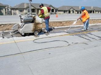
Alternative BMPs to Consider
• Not applicable
Use In Conjunction With
• SC-12 Inlet/Outlet Protection • GH-1 Vehicle and Equipment Cleaning • GH-8 Spill Prevention and Control • WM-1 Solid Waste Management • WM-6 Liquid Waste Management
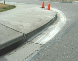
Limitations
• Finer solids are not effectively removed by filtration systems. • Chemicals and oils are difficult to capture. • Paving opportunities may be limited during wet weather to minimize discharge of pollutants.
Source: Tom Gore
Collect and contain residue from grinding/saw cutting operations by means of a vacuum.
Make sure inlets are protected before operations begin to avoid discharge into the storm drain system.
Source: Tom Gore
Effectiveness
• Most effective when paving and grinding materials are properly collected and contained and when proper procedures are understood and followed by project personnel.
Materials
• Provide material used to coat asphalt transport trucks and asphalt spreading equipment which does not contain soap, is non-foaming, and is non-toxic. • Reuse of saw-cutting water is permissible if settled and pH levels test in the normal range (6-9 pH) and water is not allowed to run off the project site.
Design and Installation Asphalt Concrete Paving
• When paving involves PMS, implement the following steps to prevent the discharge of grinding residue, un-compacted or loose asphalt concrete, tack coats, equipment cleaners, or other paving materials: - Place drip pans or absorbent materials under paving equipment while not in use, to catch and/or contain drips and leaks. - Prevent sand and gravel from new asphalt from entering storm drains or any surface water feature. Remove sand or gravel from new asphalt by sweeping, where practical. - Old or spilled asphalt must be disposed of in accordance with all laws, rules, and applicable regulations. - During chip seal application and sweeping operations, do not allow petroleum, petroleum-covered aggregate, or fine particulates to enter any storm drain or watercourse. Apply temporary perimeter control BMPs until all chip seal materials are completely cured and sweeping of excess is complete. - Use care during application of seal coat, tack coat, slurry seal, and/or fog seal near drainage inlet structures and manholes. Apply these materials by hand sprayer or brush when working adjacent to inlets, or cover drainage inlet structures and manholes with filter fabric. - Do not apply seal coat, tack coat, slurry seal, or fog seal if rainfall is predicted to occur during the application or curing period. - Asphalt millings, pieces, or chunks used in embankments or shoulder material must not be allowed to enter any storm drains or watercourses. Apply temporary perimeter control BMPs and inlet protection BMPs until structure is stabilized or permanent controls are in place. - Collect and remove all broken asphalt and recycle when practical; otherwise, dispose of in accordance with all laws, rules, and applicable regulations. - Do not wash sweepings or grindings from exposed aggregate concrete into a storm drain system. Collect and return to aggregate base stockpile or dispose of in accordance with all laws, rules, and applicable regulations. - Clean asphalt coated equipment off-site whenever possible. When cleaning dry, hardened asphalt from equipment, manage hardened asphalt debris as described in WM-1 Solid Waste Management. If needed, provide on-site cleaning operations which follow GH-1 Vehicle and Equipment Cleaning.
Portland Cement Concrete Paving
• Do not wash sweepings from exposed aggregate concrete into a storm drain system. Collect and return to aggregate base stockpile or dispose of in accordance with all laws, rules, and applicable regulations. • If aggregate is used, allow aggregate rinse to settle. Then, either allow rinse water to dry in a temporary pit as described in WM-4 Concrete Waste Management or
Design and Installation
dispose of in accordance with all laws, rules, and applicable regulations. • Do not allow saw-cut PCC slurry to enter storm drains or watercourses.
Pavement Grinding and Removal
• Collect and contain residue from grinding/saw cutting operations by means of a vacuum. Do not allow it to flow across the pavement, and do not leave it on the surface of the pavement. Also see WM-4 Concrete Waste Management, and WM-6
Liquid Waste Management. • Collect pavement dig-out material by mechanical or manual methods. This material may be recycled or, if allowed in the contract documents, used as shoulder backing or base material at locations. • If dig-out material cannot be recycled, transport the material back to a maintenance facility or approved storage site. • Do not conduct dig-out activities in the rain. • Stockpile material removed from roadways away from drain inlets, drainage ditches, and watercourses. See also GH-7 Stockpile Management. • Dispose of PCCP and PMS waste in conformance with local, tribal, state, and federal regulations. See also WM-8 Concrete Waste Management.
Thermoplastic Striping
• Inspect all thermoplastic striper and pre-heater equipment shutoff valves to ensure that they are working properly. Prevent thermoplastic from entering drain inlets, the storm water drainage system, or watercourses. • Fill the pre-heater carefully to prevent splashing or spilling of hot thermoplastic.
Leave 6 inches of space at the top of the pre-heater container when filling thermoplastic to allow room for material to move when the vehicle is deadheaded. • Do not pre-heat, transfer, or load thermoplastic near drain inlets or watercourses. • Clean truck beds daily of loose debris and melted thermoplastic. When possible recycle thermoplastic material. Dispose of thermoplastic waste in accordance with all laws, rules, and applicable regulations.
Raised/Recessed Pavement Marker Application and Removal
• Do not transfer or load bituminous material near drain inlets, the storm water drainage system or watercourses. • Load melting tanks with care and do not fill them to within 6 inches of the top to leave room for splashing when vehicle is deadheaded. • When servicing or filling melting tanks, ensure all pressure is released before removing lids to avoid spills. • On large-scale projects, use mechanical or manual methods to collect excess bituminous material from the roadway after removal of markers. • Dispose of waste material in accordance with all laws, rules, and applicable regulations.
Inspection and Maintenance
• Provide regular inspections at the frequency required by the NPDES/MPDES storm water permit to ensure proper measures are being followed. If no storm water permit is required for the project, conduct inspections as specified in the contract.
Inspection and Maintenance
• Inspect and maintain machinery regularly to minimize leaks and drips. • Ensure that project personnel are implementing appropriate measures during paving operations. • Keep ample supplies of drip pans and absorbent materials on-site.
Removal
• Dispose of wastes generated from paving and grinding operations in accordance with WM-1 through WM-6, where applicable
Definition and Purpose
Procedures and practices designed for project personnel to recognize illicit connections or illegally dumped or discharged materials on a construction site and report incidents to appropriate personnel. Illicit connections and illegal discharges or dumping, for the purposes of this BMP, refer to discharges and dumping caused by parties other than the Contractor. ☐ Construction Site Planning ☐ Temporary Soil Stabilization ☐ Run-on and Runoff Control ☐ Temporary Sediment Control ☐ Snow Management ☒ Good Housekeeping ☒ Waste Management
Objectives
AT A GLANCE
Applications
☒ Site Perimeter ☒ Inlets and Outlets ☐ Exposed Areas ☐ Sediment Traps/Basins ☐ Slopes ☒ Near Water/Wetlands ☐ Toe of Slopes ☒ Pollution/Material ☒ Ditches Sources ☐ Cut/Fill Transitions
Alternative BMPs to Consider
• Not applicable
Use In Conjunction With
• Not applicable
Limitations
• Assume that unlabeled or non-identifiable material is hazardous. • Procedures and practices presented in this BMP are generalized. Use extreme caution, immediately notify appropriate personnel when illicit connections or illegal dumping or discharges are discovered, and take no further action unless directed to do so.
Source: Tom Gore
Inspect site before beginning the job for evidence of illicit connections or illegal dumping or discharges.
Effectiveness
• Most effective when all on-site personnel are trained to recognize, understand their responsibility to report illegal or illicit discharges, and know the proper authority for reporting the activity.
Materials
• Not applicable.
Design and Installation
• Inspect site before beginning the job for evidence of illicit connections or illegal dumping or discharges.
Identification of Illicit Connections and Illegal Dumping or Discharges
• Solids - Look for debris or rubbish piles. Solid waste dumping often occurs on roadways with light traffic loads or in areas not easily visible from the traveled way. • Liquids - signs of illegal liquid dumping or discharge can include: - Visible signs of staining or unusual colors to the pavement or surrounding adjacent soils. - Pungent odors coming from the drainage systems. - Discoloration or oily substances in the water or stains and residues detained within ditches, channels or drain boxes. - Abnormal water flow during the dry weather season. • Urban Areas - Evidence of illicit connections or illegal discharges is typically detected at storm drain outfall locations or at manholes. Signs of an illicit connection or illegal discharge can include: - Abnormal water flow during the dry weather season. - Unusual flows in sub drain systems used for dewatering. - Pungent odors coming from the drainage systems. - Discoloration or oily substances in the water or stains and residues detained within ditches, channels, or drain boxes. - Excessive sediment deposits, particularly adjacent to or near active off-site construction projects. • Rural Areas - Illicit connections or illegal discharges involving irrigation drainage ditches are detected by visual inspections. Signs of an illicit discharge can include: - Abnormal water flow during the dry weather season. - Non-standard junction structures. - Broken concrete or other disturbances at or near junction structures.
Reporting
• If illicit connections and illegal dumping or discharge incidents are discovered, notify the proper authorities. This may include the Montana DEQ Enforcement Division, the city or county, local or state law enforcement, and the Department.
Cleanup and Removal
• The Contractor is not responsible for investigation and clean up of illicit or illegal dumping or discharges not generated by the Contractor; however, the Contractor can clean up nonhazardous dumped or discharged material on the construction site, if deemed appropriate to do so.
Inspection and Maintenance
• Provide regular inspections at the frequency required by the NPDES/MPDES storm water permit. If no storm water permit is required for the project, conduct inspections as specified in the contract. • Inspect site regularly during project execution for evidence of illicit connections or illegal dumping or discharges. • Observe site perimeter for evidence or potential of illicitly discharged or illegally dumped material, which may enter the job site. • Report illicit connections and illegal dumping or discharge to the proper authorities.
Removal
• The Contractor is not responsible for the clean up of illicit or illegal discharging or dumping activities, not generated by the Contractor.
Definition and Purpose
Practices and procedures to manage the discharges from irrigation water lines, landscape irrigation, lawn or garden watering, planned and unplanned discharges from potable water sources, water line flushing, and hydrant flushing. The intent is to reduce the possibility of a discharge of potential pollutants to the drainage system or watercourses. ☒ Construction Site Planning ☐ Temporary Soil Stabilization ☒ Run-on and Runoff Control ☐ Temporary Sediment Control ☐ Snow Management ☒ Good Housekeeping ☐ Waste Management
AT A GLANCE
Objectives
Applications
☐ Site Perimeter ☐ Inlets and Outlets ☐ Exposed Areas ☐ Sediment Traps/Basins ☐ Slopes ☐ Near Water/Wetlands ☐ Toe of Slopes ☒ Pollution/Material ☐ Ditches Sources ☐ Cut/Fill Transitions
Alternative BMPs to Consider
• Not applicable
Use In Conjunction With
• CP-1 Scheduling • GH-9 Water Conservation Practices • RC-1 Earth Dikes/Drainage Swales/Lined Ditches • RC-3 Temporary Slope Drains
Limitations
• None identified.
Effectiveness
• Most effective when irrigated areas are monitored regularly for leaks, saturation, and runoff.
Materials
• Not applicable.
Design and Installation
• Shut water off before cutting water pipes. • Consider factors such as soil structure, grade, type of plant material, and time of year in determining the proper amount of water for a specific area and adjust the water schedule accordingly. • Where possible, direct run-on water from off-site sources around or through a construction site in a way that minimizes contact with the construction site. • When possible, reuse discharges from water line flushing for landscaping purposes. • Shut off the water source to broken lines, sprinklers, or valves as soon as possible to prevent excess water flow. • Protect downstream storm water drainage systems and watercourses from water pumped or bailed from trenches excavated to repair water lines. • To avoid conflicts, coordinate the flushing of waterlines and hydrants prior to commencing construction.
Inspection and Maintenance
• Provide regular inspections at the frequency required by the NPDES/MPDES storm water permit. If no storm water permit is required for the project, conduct inspections as specified in the contract. • Inspect irrigated areas within the construction limits for excess watering. Adjust watering times and schedules to ensure that the appropriate amount of water is being used and to minimize runoff. • Repair broken water lines as soon as possible.
Removal
• If not required for final stabilization, remove temporary irrigation systems upon completion of the work.
Definition and Purpose
Procedures and practices implemented to minimize and prevent solid waste associated with construction activities from entering the storm drain system or watercourses. The purpose of this BMP is to control a major cause of pollution on construction sites, prevent the contamination of storm water from stockpiled waste materials, and prevent the clogging of storm drain systems. ☐ Construction Site Planning ☐ Temporary Soil Stabilization ☐ Run-on and Runoff Control ☐ Temporary Sediment Control ☐ Snow Management ☒ Good Housekeeping ☒ Waste Management
Objectives
AT A GLANCE
Applications
☐ Site Perimeter ☐ Inlets and Outlets ☐ Exposed Areas ☐ Sediment Traps/Basins ☐ Slopes ☐ Near Water/Wetlands ☐ Toe of Slopes ☒ Pollution/Material ☐ Ditches Sources ☐ Cut/Fill Transitions
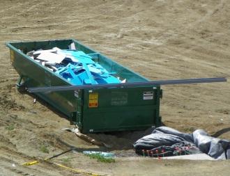
Alternative BMPs to Consider
• Not applicable
Use In Conjunction With
• RC-1 Earth Dikes/Drainage Swales/Lined Ditches • GH-5 Material Delivery and Storage • GH-6 Material Use • GH-7 Stockpile Management • WM-2 Hazardous Waste Management • WM-4 Concrete Waste Management • WM-6 Liquid Waste Management
Limitations
• It may be difficult to schedule waste disposal at projects located in remote areas.
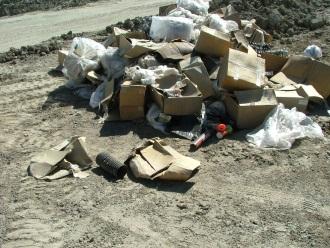
Source: Tom Gore
Designate waste storage areas and provide watertight dumpsters of sufficient size.
Do not store solid waste in uncontained locations.
Source: Tom Gore
Effectiveness
• Most effective when solid waste containers are placed in locations convenient to workers and timely disposal is provided.
Materials
• Not applicable
Design and Installation Education
• Instruct project personnel on identification of hazardous waste. • Educate project personnel on solid waste handling, storage, and disposal procedures, and require that project personnel follow appropriate procedures. • Hold regular meetings to discuss and reinforce disposal procedures (incorporate into regular safety meetings). • Prohibit littering by project personnel and visitors. • Wherever possible, minimize production of solid waste materials.
Collection, Storage, and Disposal
• Designate waste storage areas and provide watertight dumpsters of sufficient size and number to contain the solid waste generated by the project. In addition, provide trash receptacles in the yard, field trailer areas, and at locations where workers congregate for lunch and break periods. • Locate solid waste storage areas at least 50 feet from drainage facilities and watercourses and outside of areas prone to flooding or ponding. Prevent storm water run-on from contacting stored solid waste through the use of berms, dikes, or other temporary diversion structures, or through the use of measures to elevate waste form site surfaces. Regularly collect litter from work areas within the construction limits of the project site and placed it in watertight dumpsters regardless of whether the litter was generated by project personnel, the public, or others. • Handle and dispose of litter stored in collection areas and containers using trashhauling Contractors. Emptied or remove full dumpsters from the project site in a timely manner. • Maintain materials that are disposed of or temporarily stockpiled outside the rightof-way, but which are visible from the roadway, in a neat and orderly fashion. • Provide covers for dumpsters and waste containers to prevent entry of rainwater and/or loss of contents by high winds. Protect solid waste not stored in containers from wind and rain by securely covering the waste with tarps or plastic sheeting. • Dumpster washout on the project site is not allowed. • Plan for additional containers and/or more frequent pickup during the demolition phase of construction. • Segregate potentially hazardous waste and liquid waste from non-hazardous construction site solid waste. Additional handling and disposal requirements for hazardous materials and liquid waste are included in WM-2 and WM-6, respectively. • Salvage or recycle useful vegetation debris, packaging, and/or surplus building materials when practical. For example, trees and shrubs from land clearing can be used as a brush barrier, or converted into wood chips and used as mulch. Wood pallets, cardboard boxes, and construction scraps can be recycled. • Dispose of all non-salvageable materials in accordance with all laws, rules, and applicable regulations.
Inspection and Maintenance
• Provide regular inspections of the project site and solid waste receptacles at the frequency required by the NPDES/MPDES storm water permit to ensure proper solid waste management measures are being followed. If no storm water permit is required for the project, conduct inspections as specified in the contract. • Check for, and remove, litter and debris from drainage grates, trash racks, ditch lines, and other drainage structures. • Inspect waste receptacles for leaks, inadequate covers, or ineffectiveness and remedy deficiencies.
Removal
• At the conclusion of the project, clean up all affected areas and empty/remove all waste receptacles.
Definition and Purpose
Procedures and practices implemented to prevent hazardous waste associated with construction activities from entering the storm drain system or watercourses. The purpose of this BMP is to control the release of hazardous materials, prevent contamination of storm water, and prevent delay in the project schedule and additional costs and fees due to environmental investigations/enforcement actions. ☐ Construction Site Planning ☐ Temporary Soil Stabilization ☐ Run-on and Runoff Control ☐ Temporary Sediment Control ☐ Snow Management ☒ Good Housekeeping ☒ Waste Management
Objectives
AT A GLANCE
Applications
☐ Site Perimeter ☐ Inlets and Outlets ☐ Exposed Areas ☐ Sediment Traps/Basins ☐ Slopes ☐ Near Water/Wetlands ☐ Toe of Slopes ☒ Pollution/Material ☐ Ditches Sources ☐ Cut/Fill Transitions
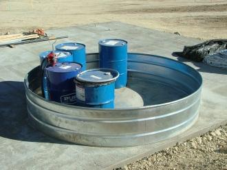
Alternative BMPs to Consider
• Not applicable
Use In Conjunction With
• GH-2 Vehicle and Equipment Fueling • GH-3 Vehicle and Equipment Maintenance • GH-5 Material Delivery and Storage • GH-6 Material Use • GH-8 Spill Prevention and Control • WM-1 Solid Waste Management • WM-3 Contaminated Soil Management
Limitations
• Nothing in this BMP relieves the Contractor from responsibility for compliance with federal, state, tribal, and local laws and regulations regarding storage, handling, transportation, and disposal of hazardous wastes. Coordinate storage, handling, transportation, and disposal of hazardous or deleterious materials through appropriate MDT,
DEQ, and/or tribal staff. • This BMP does not cover ADL soils. For ADL soils, refer to WM-3 Contaminated Soil Management.
Source: Tom Gore
Store hazardous waste in sealed containers with secondary containment.
Effectiveness
• Most effective when implemented in conjunction with a comprehensive spill prevention plan.
Materials
• Not applicable
Design and Installation
• Comply with all federal, state, tribal, and local laws regarding hazardous materials on a construction site.
Education
• Educate project personnel on the identification of hazardous wastes, storage and disposal procedures, and the potential dangers hazardous wastes pose to humans and the environment. • Instruct project personnel on safety procedures for common construction site hazardous wastes. • Hold regular safety meetings to discuss and reinforce hazardous waste management procedures. • Ensure that all hazardous waste is collected, removed, and disposed of in accordance with all laws, rules, and applicable regulations.
Storage Procedures
• Store, transport, and dispose of all hazardous waste in accordance with all laws, rules, and applicable regulations. • Designate hazardous waste storage areas on site away from storm drains or watercourses, moving vehicles and equipment, sensitive habitats, and areas prone to flooding or ponding. • Ensure that hazardous waste collection containers are conveniently located. • Minimize production or generation of hazardous materials and hazardous waste on the job site. • Do not allow potentially-hazardous waste materials to accumulate on the ground. • Segregate potentially hazardous waste from non-hazardous construction site debris. • Keep liquid or semi-liquid hazardous waste in appropriate containers (closed drums or similar) and under cover. • Store hazardous waste in sealed containers constructed of suitable material and clearly labeled with the waste being stored and the date of accumulation. Do not overfill containers or mix wastes. Unless watertight, store containers of dry waste on pallets. • Place hazardous waste containers in secondary containment. • Store waste containers in temporary containment facilities that comply with the following requirements. - Provide temporary containment facilities with a spill containment volume equal to 1.5 times the volume of all containers stored within the facility. - Provide temporary containment facilities which are impervious to the materials contained therein for a minimum contact time of 72 hours. - Maintained temporary containment facilities free of accumulated rainwater and spills. - Provide sufficient separation between stored containers to allow for spill clean up and emergency response access. - Do not store incompatible materials, such as chlorine and ammonia, in the same temporary containment facility.
Design and Installation
- Throughout the rainy season, cover temporary containment facilities during nonworking days, prior to rain events. • Clean paint brushes and equipment for water and oil based paints within a contained area and do not allow waste materials to contaminate site soils, watercourses, or drainage systems. Dispose of waste paints, thinners, solvents, residues, and sludges that cannot be recycled or reused as hazardous waste. When thoroughly dry, latex paint and paint cans, used brushes, rags, absorbent materials, and drop cloths may be disposed of as solid waste. Use containment berms in fueling and maintenance areas, and where the potential for spills is high.
Disposal Procedures
• Dispose of hazardous waste in accordance with all laws, rules, and applicable regulations. • To minimize on-site storage, dispose of full containers of waste in accordance with all laws, rules, and applicable regulations. • Dispose of hazardous waste using a licensed transporter at an authorized and licensed disposal facility or recycling facility utilizing properly completed Uniform
Waste Manifest forms. • Sample and test potentially hazardous wastes using an MDT-certified laboratory to determine the appropriate disposal facility. • Make sure that toxic liquid wastes (used oils, solvents, and paints) and chemicals (acids, pesticides, additives, curing compounds) are not disposed of in dumpsters designated for solid waste construction debris. • Dispose of rainwater in secondary containment that may have mixed with hazardous waste. Recycle any useful material, such as used oil or water-based paint when practical.
Inspection and Maintenance
• Provide regular inspections at the frequency required by the NPDES/MPDES storm water permit to ensure proper hazardous waste management measures are being followed. If no storm water permit is required for the project, conduct inspections as specified in the contract. • Keep hazardous waste storage areas clean, well organized, and equipped with ample clean up supplies appropriate for the materials being stored. • Repair or replace perimeter controls, containment structures, covers, and liners as needed to maintain proper function. • Clean up and report hazardous spills in conformance with the applicable MSDS and the instructions posted at the project site. • Notify the National Response Center, at (800) 424-8802, of spills of federal reportable quantities in conformance with Federal regulations • Provide a copy of Bill of Lading and disposal receipts to MDT.
Removal
• At the conclusion of the project, remove all hazardous materials from the project site.
Definition and Purpose
Procedures and practices implemented to minimize or prevent pollutants from contaminated soil associated with construction activities from entering the storm drain system or watercourses. ☐ Construction Site Planning ☐ Temporary Soil Stabilization ☐ Run-on and Runoff Control ☐ Temporary Sediment Control ☐ Snow Management ☒ Good Housekeeping ☒ Waste Management
Objectives
AT A GLANCE
Applications
☐ Site Perimeter ☐ Inlets and Outlets ☐ Exposed Areas ☐ Sediment Traps/Basins ☐ Slopes ☐ Near Water/Wetlands ☐ Toe of Slopes ☒ Pollution/Material ☐ Ditches Sources ☐ Cut/Fill Transitions
Alternative BMPs to Consider
• Not applicable
Use In Conjunction With
• GH-8 Spill Prevention and Control • WM-2 Hazardous Waste Management
Limitations
• The procedures and practices presented in this BMP are generalized. Identify appropriate practices and procedures for the specific contaminants known to exist or discovered on site.
Source: Tom Gore
Properly contain and label contaminated soils temporarily stored on site.
Effectiveness
• Most effective when project personnel are educated in the identification of contaminated soils as well as proper handling, storage, and disposal requirements.
Materials
• Not applicable.
Design and Installation Identifying Contaminated Areas
• Contaminated soils are often identified during project planning and development with known locations indicated in the plans and specifications. Review applicable reports and investigate appropriate call-outs in the plans and specifications. • Further identify contaminated soils by investigating: - past site uses and activities, - detected or undetected spills and leaks, and - acid or alkaline solutions from exposed soil or rock formations high in acid or alkaline forming elements. • Look for contaminated soil as evidenced by discoloration, odors, differences in soil properties, abandoned underground tanks or pipes, or buried debris. Test suspected soils at a certified laboratory.
Education
• Prior to performing any excavation work at the locations containing material classified as hazardous, ensure that project personnel complete a safety training program which meets federal regulations and covers the potential hazards as identified. • Educate project personnel in identification of contaminated soil and on contaminated soil handling and disposal procedures. • Hold regular safety meetings to discuss and reinforce disposal procedures.
Handling Procedures for Material with ADL
• Materials from areas designated as containing ADL may, if allowed by the contract special provisions, be excavated, transported, and used in the construction of embankments and/or backfill. • Ensure that excavation, transportation, and placement operations result in no visible dust. • Use caution to prevent spillage of lead-containing material during transport. • Monitor air quality during excavation of soils contaminated with lead.
Handling Procedures for Contaminated Soils
• Test suspected soils at an MDT-approved certified laboratory. • If the soil is contaminated, work with the local regulatory agencies to develop options for treatment and/or disposal. • Avoid temporary stockpiling of contaminated soils or hazardous material. • If temporary stockpiling is necessary: - cover the stockpile with plastic sheeting or tarps, - install a berm around the stockpile to prevent runoff from leaving the area, and - do not stockpile in or near storm drains or watercourses or areas prone to flooding or ponding. • Remove contaminated material and hazardous material from the exterior of transport vehicles and either place the material in the current transport vehicle or the excavation prior to the vehicle leaving the exclusion zone.
Design and Installation
• Monitor air quality continuously during excavation operations at all locations containing hazardous material. • Procure all permits and licenses, pay all charges and fees, and give all notices necessary and incidental to the due and lawful prosecution of the work, including registration for transporting vehicles carrying the contaminated material and the hazardous material. • Collect water from decontamination procedures, treat, and/or dispose of it in accordance with all laws, rules, and applicable regulations. • Collect non-reusable protective equipment, once used by any personnel, and dispose of it at an appropriate disposal facility. • Install temporary security fence to surround and secure the exclusion zone. Remove fencing when no longer needed. • Excavate, transport, and dispose of contaminated material and hazardous material in accordance with all laws, rules, and applicable regulations.
Procedures for Underground Storage Tank Removals
• Prior to commencing tank removal operations, obtain the required underground storage tank removal permits and approval from the federal, state, tribal, and local agencies, which have jurisdiction over such work. • Arrange to test any liquid or sludge found in the underground tank prior to its removal to determine if it contains hazardous substances. • Following the tank removal, take soil samples beneath the excavated tank and perform analysis as required by the local agency representative(s). • Transport the underground storage tank, any liquid and/or sludge found within the tank, and all contaminated substances and hazardous substances removed during the tank removal to disposal facilities permitted to accept such waste.
Water Control
• Take all necessary precautions and preventive measures to prevent the flow of water, including ground water, from mixing with hazardous substances or underground storage tank excavations. Such preventative measures may consist of, but are not limited to: berms, cofferdams, grout curtains, freeze walls, and seal course concrete or any combination thereof. • If water does enter an excavation and becomes contaminated, discharge such water, when necessary to proceed with the work, to clean, closed-top, water-tight holding tanks; treat; and dispose of in accordance with all laws, rules, and applicable regulations.
Inspection and Maintenance
• Provide regular inspections at the frequency required by the NPDES/MPDES storm water permit to ensure proper contaminated soil management measures are being followed. If no storm water permit is required for the project, conduct inspections as specified in the contract. • Monitor air quality continuously during excavation operations at all locations containing hazardous material. • Coordinate contaminated soils and hazardous substances/waste management with the appropriate federal, state, tribal, and local agencies. • Inspect hazardous waste receptacles and areas regularly.
Removal
• Analytical testing of the soil at an accredited laboratory will be necessary prior to disposal. • Disposal of the soil must be at a licensed disposal facility.
Definition and Purpose
Procedures and practices implemented to minimize or prevent pollutants from concrete waste materials associated with construction activities from entering the storm drain system or watercourses. ☐ Construction Site Planning ☐ Temporary Soil Stabilization ☐ Run-on and Runoff Control ☐ Temporary Sediment Control ☐ Snow Management ☒ Good Housekeeping ☒ Waste Management
Objectives
AT A GLANCE
Applications
☐ Site Perimeter ☐ Inlets and Outlets ☐ Exposed Areas ☐ Sediment Traps/Basins ☐ Slopes ☐ Near Water/Wetlands ☐ Toe of Slopes ☒ Pollution/Material ☐ Ditches Sources ☐ Cut/Fill Transitions
Alternative BMPs to Consider
• Not applicable
Use In Conjunction With
• SC-9 Sandbag Barrier • SC-12 Inlet/Outlet Protection • GH-10 Paving and Grinding Operations • WM-1 Solid Waste Management • WM-6 Liquid Waste Management
Limitations
• None identified.
Effectiveness
• Most effective when concrete washout facilities are placed at convenient locations near pour sites, and when facilities are monitored and cleaned to provide sufficient storage volume.
Source: Tom Gore
Provide properly-contained temporary washout facilities with areas of sufficient volume to completely contain all liquid.
Concrete washout and slurry cannot be wasted to the ground. It must be properly contained.
Source: Tom Gore
Materials
• Not applicable.
Design and Installation Education
• Educate project personnel and suppliers on the concrete waste management techniques described herein.
Concrete Slurry Wastes
• Do not allow PCC and PMS waste, including but not limited to, slurries generated from saw-cutting, coring, grinding, milling, grooving, and hydro demolition to enter storm drains or watercourses. • Collect and dispose of PCC and PMS waste in accordance with all laws, rules, and applicable regulations. • Do not allow slurry residue from wet coring or saw-cutting PMS or PCC to enter storm drains or receiving waters by: - placing temporary berms or sandbags around coring or saw-cutting locations to capture and contain slurry runoff; - placing sandbags or gravel dams around inlets to prevent slurry from entering storm drains; - vacuuming slurry waste or collecting it in a temporary pit and allowing it to dry; and - properly disposing of slurry residue. • Dispose of hardened PCC and PMS waste as solid waste in accordance with WM-1 unless the material is to be reused on site in embankments, as base course, as surfacing, or as traffic gravel. • Install a sign adjacent to each temporary concrete washout facility to inform concrete equipment operators to utilize the proper facilities. • Below-grade concrete washout facilities are typical. Above grade facilities are used if excavation is not practical. • Collect and dispose of slurry residue as well as residue from grooving and grinding operations in a temporary pit (as described in On-site Temporary Concrete Washout
Facility, Concrete Transit Truck Washout Procedures, below) and allow slurry to dry.
Dispose of dry slurry residue as solid waste in accordance with WM-1.
On-site Temporary Concrete Washout Facility & Transit Truck Washout Procedures
• Locate temporary concrete washout facilities a minimum of 50 feet from storm drain inlets, open drainage facilities, and watercourses and away from construction traffic or access areas to prevent disturbance or tracking. Locate concrete washout facilities near the pour site whenever practical for convenient truck access. • Provide multiple washout locations for sites with extensive concrete work or multiple, dispersed pour locations. • Install a sign adjacent to each washout facility to inform concrete equipment operators to utilize the proper facilities. • Temporary concrete washout facilities may be constructed above grade or below
Design and Installation
grade, but must be constructed and maintained in sufficient quantity and size to contain all liquid and concrete waste generated by washout operations. • Provide temporary washout facilities with a temporary pit or bermed areas of sufficient volume to completely contain all liquid and waste materials generated during washout procedures. • Perform washout of concrete trucks in designated areas only. • Once concrete wastes are washed into the designated area and allowed to harden, break up the concrete, remove, and disposed of as solid waste in accordance with
WM-1. Dispose of hardened concrete on a regular basis. • Temporary Concrete Washout Facility (Type Above Grade) - Construct temporary concrete washout facilities (type above grade) with a recommended minimum length and minimum width of 10 feet. Provide a quantity and volume sufficient to contain all liquid and concrete waste generated by washout operations. - Provide polyethylene lining material with a minimum of 60 mils and which is free of holes, tears, or other defects that could compromise the impermeability of the material. - Provide flexible delineators which conform to the provisions of the contract. Adhere the delineator bases to the pavement. Apply delineators only to a clean, dry surface. • Temporary Concrete Washout Facility (Type Below Grade) - Construct temporary concrete washout facilities (type below grade) with a recommended minimum length and minimum width of 10 feet. Provide a quantity and volume sufficient to contain all liquid and concrete waste generated by washout operations. - Provide polyethylene lining material with a minimum of 60 mils and which is free of holes, tears, or other defects that could compromise the impermeability of the material.
Inspection and Maintenance
• Provide regular inspections at the frequency required by the NPDES/MPDES storm water permit to ensure proper concrete waste management measures are being followed. If no storm water permit is required for the project, conduct inspections as specified in the contract. • Maintain temporary concrete washout facilities to provide adequate holding capacity with a minimum freeboard of 4 inches, for above grade facilities, and 12 inches, for below grade facilities. Maintaining temporary concrete washout facilities includes removing and disposing of hardened concrete and returning the facilities to a functional condition. • Clean or provide new temporary washout facilities once the washout is 75% full.
Removal
• When temporary concrete washout facilities are no longer required for the work, remove the hardened concrete and disposed of it as solid waste in accordance with
WM-1. Remove materials used to construct temporary concrete washout facilities from the work site, and dispose of them in accordance with all laws, rules, and
Removal
applicable regulations. • Backfill and repair holes, depressions, or other ground disturbance caused by the removal of the temporary concrete washout facilities.
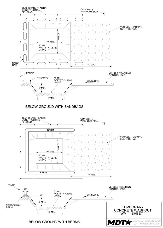
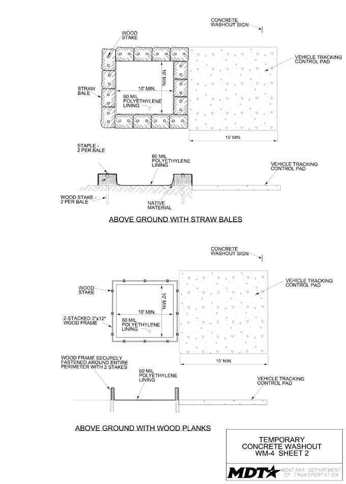
Definition and Purpose
Procedures and practices implemented to minimize or prevent the discharge of construction site sanitary/septic waste materials to the storm drain system or watercourses. ☐ Construction Site Planning ☐ Temporary Soil Stabilization ☐ Run-on and Runoff Control ☐ Temporary Sediment Control ☐ Snow Management ☒ Good Housekeeping ☒ Waste Management
Objectives
AT A GLANCE
Applications
☐ Site Perimeter ☐ Inlets and Outlets ☐ Exposed Areas ☐ Sediment Traps/Basins ☐ Slopes ☐ Near Water/Wetlands ☐ Toe of Slopes ☒ Pollution/Material ☐ Ditches Sources ☐ Cut/Fill Transitions
Alternative BMPs to Consider
• Not applicable
Use In Conjunction With
• GH-11 Illicit Discharge Detection and Reporting • WM-1 Solid Waste Management • WM-5 Liquid Waste Management
Limitations
• None identified.
Effectiveness
• Most effective when sanitary facilities are placed away from drainage facilities, watercourses, and traffic circulation; when portable toilets are properly secured; and when project personnel and suppliers understand and follow sanitary/septic waste storage and disposal procedures.
Source: Tom Gore
Station portable toilets in designated staging areas.
Provide appropriate containment for leaking facilities.
Source: Tom Gore
Materials
• Not applicable.
Design and Installation Education
• Educate project personnel and suppliers on sanitary/septic waste storage and disposal procedures and on the potential dangers sanitary/septic waste poses to humans and the environment. • Instruct project personnel and suppliers in identification of sanitary/septic waste. • Hold regular safety meetings to discuss and reinforce disposal procedures.
Storage and Disposal Procedures
• Locate temporary sanitary facilities away from drainage facilities, watercourses, and from traffic circulation. • Do not locate temporary sanitary facilities in areas that will collect water. • Provide containment for spill or leak protection. • Stake portable toilets or secure to a sturdy object (such as a fence or post) to create a stable environment and prevent overturning. • Do not discharge or bury wastewater within the right-of-way. • Ensure that sanitary and septic systems that discharge directly into sanitary sewer systems, where permissible, comply with the local health agency, city, county, and sewer district requirements. • Properly connect temporary sanitary facilities that discharge to the sanitary sewer system to avoid illicit discharges. • Ensure that sanitary/septic facilities are maintained in good working order by a licensed service. • Use only reputable, licensed sanitary/septic waste-haulers.
Inspection and Maintenance
• Provide regular inspections at the frequency required by the NPDES/MPDES storm water permit to ensure proper sanitary/septic waste management measures are being followed. If no storm water permit is required for the project, conduct inspections as specified in the contract. • Inspect facilities for leaks or spills and repair leaks or replace facility immediately. • Arrange for regular waste collection.
Removal
• Remove all temporary sanitary facilities once construction is complete. • Conduct the removal of sanitary waste using reputable, licensed sanitary/septic waste-haulers.
Definition and Purpose
Procedures and practices to prevent discharge of pollutants to the storm drain system or to watercourses as a result of the creation, collection, and disposal of non-hazardous liquid wastes. Example sources of liquid waste include drilling slurries and drilling fluids, grease/oil-free wastewater and rinse water, dredgings, and curing compounds. Compliance with all appropriate local, state, tribal, and federal regulations is required. ☐ Construction Site Planning ☐ Temporary Soil Stabilization ☐ Run-on and Runoff Control ☐ Temporary Sediment Control ☐ Snow Management ☒ Good Housekeeping ☒ Waste Management
Objectives
AT A GLANCE
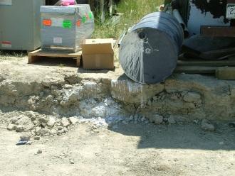
Applications
☐ Site Perimeter ☐ Inlets and Outlets ☐ Exposed Areas ☐ Sediment Traps/Basins ☐ Slopes ☐ Near Water/Wetlands ☐ Toe of Slopes ☒ Pollution/Material ☐ Ditches Sources ☐ Cut/Fill Transitions
Alternative BMPs to Consider
• Not applicable
Use In Conjunction With
• RC-1 Earth Dikes/Drainage Swales/Lined Ditches • SC-3 Sediment Trap • GH-1 Vehicle and Equipment Cleaning • GH-8 Spill Prevention and Control • WM-2 Hazardous Waste Management • WM-4 Concrete Waste Management
Limitations
• Disposal of some liquid wastes may be subject to specific laws and regulations, or to requirements of other permits secured for the project.
Source: Tom Gore
Containment devices must be of sufficient size to completely contain the liquid wastes generated.
Containment devices must be structurally sound and leak free.
Source: Tom Gore
• Does not apply to solid waste management (see WM-1), hazardous wastes (see
WM-2), or concrete slurry residue (see WM-4).
Effectiveness
• Most effective when project personnel are educated in the identification of potential, or known, hazardous liquid waste as well as proper handling, storage, and disposal requirements.
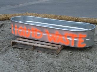
Materials
• Not applicable.
Design and Installation General Practices
• Adhere to all permit requirements and federal, state, tribal, and local regulations for properly disposing of liquid waste. Instruct project personnel how to safely differentiate between non-hazardous liquid waste and potential, or known, hazardous liquid waste. • Instruct project personnel and suppliers that it is unacceptable for any liquid waste to enter any storm drainage device, waterway, or receiving water. • Educate project personnel on liquid-waste-generating activities, and liquid waste storage and disposal procedures. • Hold regular safety meetings to discuss and reinforce proper disposal procedures. • Apply GH-1 Vehicle and Equipment Cleaning for managing wash water and rinse water from vehicle and equipment cleaning operations.
Containing Liquid Wastes
• Do not allow drilling residue and drilling fluids to enter storm drains and watercourses, and dispose of it in accordance with all laws, rules, and applicable regulations. • If an appropriate location is available, drilling residue and drilling fluids may be dried by infiltration and evaporation in a containment facility constructed in conformance with the provisions concerning the temporary concrete washout facilities detailed in WM-4 Concrete Waste Management. • Contain liquid wastes generated as part of an operational procedure, such as waterladen dredged material and drilling mud, and do not allow it to flow into drainage channels or receiving waters prior to treatment. • Contain liquid wastes in a controlled area, such as a holding pit, sediment basin, or portable tank. • Containment devices must be structurally sound and leak free. • Containment devices must be of sufficient quantity or volume to completely contain the liquid wastes generated. • Take precautions to avoid spills or accidental releases of contained liquid wastes.
Apply the education measures and spill response procedures outlined in GH-8 Spill
Prevention and Control. • Do not locate containment areas or devices where accidental release of the contained liquid can threaten health or safety, or discharge to water bodies, channels, or storm drains.
Capturing Liquid Wastes
• Capture all liquid wastes which have the potential to affect the storm drainage system, such as wash water and rinse water. • Do not allow liquid wastes to flow or discharge uncontrolled. Use temporary dikes or berms to intercept flows and direct them to a containment area or device for capture.
Design and Installation
• If the liquid waste is sediment laden, use a sediment trap (see SC-3 Sediment Trap) for capturing and treating the liquid waste stream, or capture in a containment device and allow sediment to settle.
Disposing of Liquid Wastes
• Typical method is to dewater the contained liquid waste using procedures such as described in SC-2 Desilting Basin, and dispose of resulting solids per WM-1 Solid
Waste Management. • Method of disposal for some liquid wastes is prescribed in the contract and applicable regulations. • Liquid wastes, such as from dredged material, may require testing and certification whether it is hazardous or not before a disposal method can be determined. • For disposal of hazardous waste, see WM-2 Hazardous Waste Management. • If necessary, further treat liquid wastes prior to disposal. Treatment may include, but not necessarily be limited to, sedimentation, filtration, and chemical neutralization.
Inspection and Maintenance
• Provide regular inspections at the frequency required by the NPDES/MPDES storm water permit to ensure proper liquid waste management measures are being followed. If no storm water permit is required for the project, conduct inspections as specified in the contract. • Spot check project personnel at least monthly throughout the job to ensure appropriate practices are being employed. • Remove deposited solids in containment areas and capturing devices as needed, and upon completion of the task. Dispose of any solids as described in WM-1 Solid
Waste Management. • Inspect containment areas and capturing devices frequently for damage, and repair as needed.
Removal
• When containment facilities such as holding pits, sediment basins, or portable tanks are no longer required for the work, remove deposited sediments and disposed of as solid waste in accordance with WM-1. Remove materials used to construct containment facilities when no longer required or upon completion of the work, and dispose of materials in accordance with all laws, rules, and applicable regulations. • Backfill and repair holes, depressions, or other ground disturbance caused by the removal of the containment facilities.
