10 minute read
Design Study of a Slip-In Tube Propeller Shaft


Chapter 1 – Introduction (Background of study
A Drive Shaft is a mechanical component which delivers torque and rotational energy by connecting through the powertrain and differential. Drive shafts are subjected to high torsionalandshearstressfromtheinputtorqueandload(S.KShoaib Nadeem,G.Giridhara, H.KRangavittal2018).Therefore,itiscrucialthat theyarestrongenoughto bearthestress, avoiding too much weight which can then cause an increase of inertia. The problem of drive shafts is common and causes of deformation after a long period of stress and load on them may subject to flexion on theshaft. This document proposes a literature review of improving a drive shaft design. The proposedreview discusses on improvement of the design aspects for economic reasons and reliability of thecomponent. The drive shaft connects the transmission to the rear axle input, it also acts as a torsional damper between the transmission and rear axle. This protects both transmission from rearaxle stall and protects the rear axle from harmful transmission accelerations. Therefore, this in return can help by improving the life span of the vehicle’s drive train.
Advertisement
1.2 Problem Statement: Drive shafts of most rear wheel drive and 4WD are very durable, but thisdoes not mean they cannot wear and fail. A vehicle’s drive shaft is the rotating part located betweenthe gearbox and differential, it helps by switching from idle to drive and without it, the vehicle would not move. A drive shaft problem can be known when putting the vehicle in gear as power is transmitted from the gearbox to the rear axle, the worn or damagedcomponentgivewayand resultinginsuddencrunchorpopsound.Therearemany reasonsastotheproblemofadriveshaftand various symptoms that indicateif the vehicle’s drive shaft is faulty. A common problem of drive shaft would be vibration when speed and torqueincreases, and thiscan causeharshdrivinginstabilityofthevehicle(itstillruns.com).
The cardan shaft’s universal joint is one of contributing reason and it will not only cause vibrationsbut have clicking and loud clunking sounds too. This is important as it may cause the driver and passengers of the vehicle to feel uncomfortable especially on long journey (yourmechanic.com).
Once a vehicle drive shaft is damaged caused by torsion and shear forces, it can give difficulty inmaking turns and in some instance the vehicle shudders during acceleration from starting or low speed, while a loose universal joint issue can also cause shuddering during acceleration (moogparts.com).
However, these can all be solved during the design process by having a better design structure andmaterials such as reducing the design of the shaft to be compact while using composite and epoxymaterials which can have high specific stiffness, strength, corrosion resistance, wear resistance, light weight properties and so on. The benefits of this will be in terms of reliability and at the sametime achieving an optimum design outcome which can benefit both the manufacturer as well as customers.
1.3 Objectives: The purpose to this literature review is about the use of good design practice of the drive shaft that can help enhance the value of the stated product. In this review, the followinggoals desire to be achieve are:
1. Improvements of the propeller drive shaft designs in terms of weight to durability ratio.
2. Analyzes the safe design of the drive shaft to be improved to help reduce wear on universaljoints through types of material use.
3. Study and analyzethe driveshaft inorder to improveefficiency and safety oftheshaft withbetter safety factors through optimized design.
1.4 Scope of the project: The scope of this project will encompass the Slip-In Tube drive shaft component design, the calculations of the parts, a design study through research, multiple testing of prototype design materials, results of analysis, selection of a design, selected design specifications and findings on the report.
1.5 Aim of the project: The aim as stated is to look for a better drive shaft design and therefore improving on the product to be strong, reliability and simplicity for ease of maintenance and aftersales value of the product.
2.1 Introduction
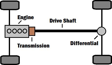
Drive shafts played an important role in the power transmission application, it is used as a powertransmission part in the automobile. A drive shaft’s purpose primarily is to deliver torque from the transmission to the differential, which then transmit this torque to the wheels in order to move the vehicle. The primary function is to allow torque transfer between components that are separated by a distance, since different type of components must be at different locations in the vehicle. For example, a front-engine rear wheel drive car requires to have a long drive shaft connecting the rear axle to the transmission since these parts are on opposite sides of the car.
The drive shaft is used to deliver the torque and rotation energy while is being subjected to a high torsional shear stress and strain from input torque and load. In addition, this raises the issue on torsion, buckling, natural bending frequency and the weight of the drive shaft. Drive shafts today are increasingly using materials which are made from composite material, replacing conventional metallic structure such as steel which are commonly used in vehicles and as well asaluminum materials.
In the automobile, a drive shaft allows for variations in the alignment and distance between the driving and driven components through the use of universal joints and spline joint. As with this, it connects at both ends to transmit power at angle which is crucial for a well working drive shaftpoint of view.
2.2 Types of drive shaft
There are three types of driveshaft configurations, one is a single cardan u-joint and the other will be a double cardan u-joint. They are also known as one-piece drive shaft and two-piece drive shaft; the third type however is the slip-in-tube drive shaft. The single piece is sometimes called a short drive shaft when a transfer box is centrally mounted. A longer drive shaft is neededin some vehicle as they are able to cover the distance, these drive shafts are the two-piece type drive shaft. Slip-in-tube are known as collapsible drive shaft because it can fold in the event of an accident which thus making it a safer shaft design. Although, there are single drive shaft that runs the length of the car to the rear axle, this is a favored design where the torque is biased to the front wheels to give car-like handling, or where the maker wishes to produce both four-wheeldrive and front-wheel drive cars with many shared components.

2.2.1 Different types of drive shaft
Driveshafts comes in several designs depending on the use of the vehicle, this meant for certaintypes of function it can perform. It has shaft design for passenger cars, lorry, trucks, buses and others. Each are designed differently for their specific task.
2.2.2 Single shaft drive
A conventional one-piece drive shaft is easier to manufacture and the cost of maintenance andbuying is also cheaper than other types. The friction welded joints enables improvement of strength of the shaft but what it lacks in is the amount of flex on the shaft angle.
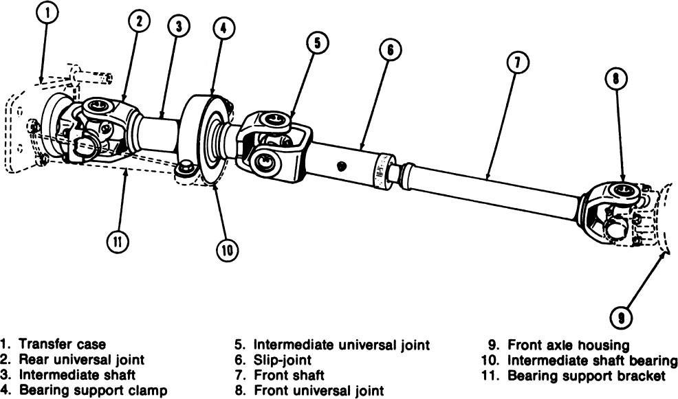
2.2.3 Two-piece shaft
Some long wheelbase vehicles use a two-piece drive shaft, a centre support bearing and slip joint is normally included at the centre of the shaft and some does not. Advantage for this is it allows for the critical number of revolutions to be lowered preventing vibration problems from occurring when the overall length of the shaft has increased. Disadvantage would be complexity and cost concern for this driveshaft.
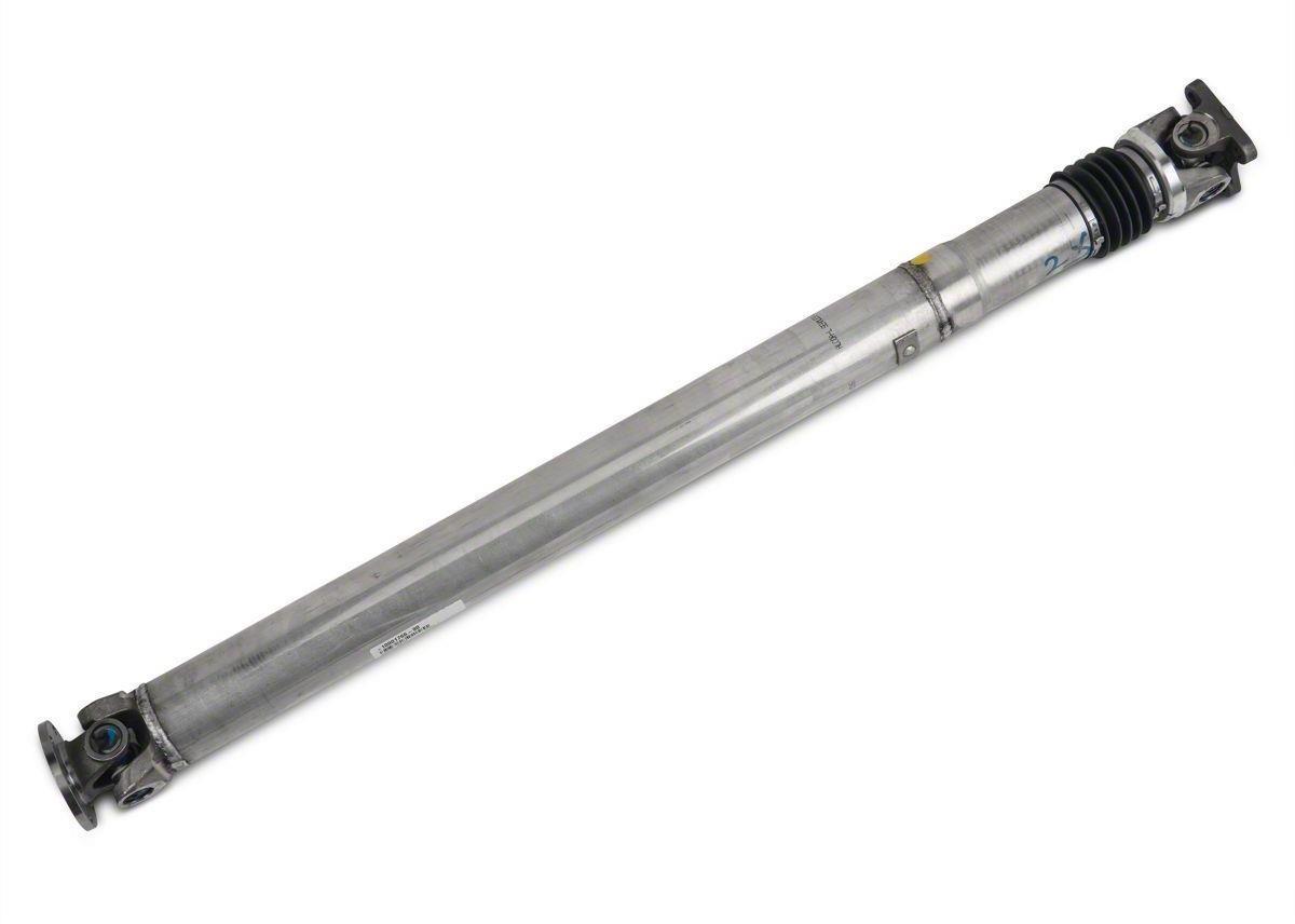
2.2.4 Slip-in tube shaft
A slip-in tube works like a two-piece shaft but with additional shaft movement from the spline it can have a greater degree of angle of motion. Furthermore, it can extend or contract in shaft length and this help in lessen the vibrations and load on the drive shaft components.
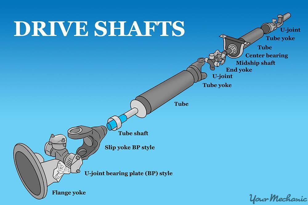
2.3 Components of a drive shaft
Stub Slip Yoke – connects the transmission output shaft to the front universal joint
Front Universal Joint – the swivel connection that fasten the slip yoke to the drive shaft
Drive Shaft – a hollow metal tube that transfer turning power from the front universal joint to the rear universal joint
Rear Universal Joint – a flex joint that connects the drive shaft to the differential yoke
Rear Yoke – holds the rear universal joint and transfers torque to the gears in the rear axle assembly
Centre Support Bearing – helps to support the longer drive shaft on mid-size and heavy-duty vehicles
(example of components in a drive shaft)
2.3.1 Sub-components
Universal-JointAssembly
Flange Yoke – part of universal joint assembly, it is a two joint fork halves, each comprise of a base component and bearing component. It is a hub that forms as a lock for the pilot receiver and joins with the companion flange.
Journal – As part of the assembly, journals are connected to the flange yoke and splined sliding yoke to allow pivot on the axis of the journal and also permits the transmission of rotary motion from one yoke to the other (Chris Johanson, 2004, Goodheart-Wilcox Publ.).
Roller Bearing – To allow a smooth rotation of the universal joint.
Snap Ring – To secure the bearing caps or yoke bores of universal joint.
Oil Seal – To secure the lubricating oil on the U-joint used for lubrication.
Splined Sliding Yoke – Connects the drive shaft, to serve the purpose of telescopic action as axle housing moves forward and backward while the slip yoke gives freedom of movement in horizontal direction and is capable of transmitting rotary motion.
2.4 Drive shaft working principles
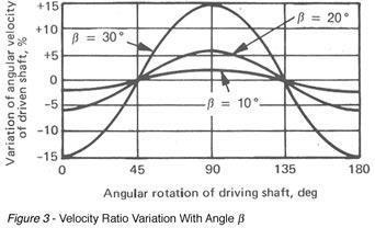
A drive shaft principle is a component of drive train in a vehicle, with the purpose of delivering torque from the transmission to the differential, which is then transmit this torque to the drive wheels in order to get the car to move. (J.M.K.C. Donev et al. (2018). Energy Education - Drive shaft). The u-joints speeds up and slow down twice per revolution and increased in operating angle means increased speed variation. The drive shaft has to have good alignment as well and same angle to cancel out vibrations. Input and output drive shaft angles equal but not excessive, which means it has to be at a small angle of not more than 4 degrees.

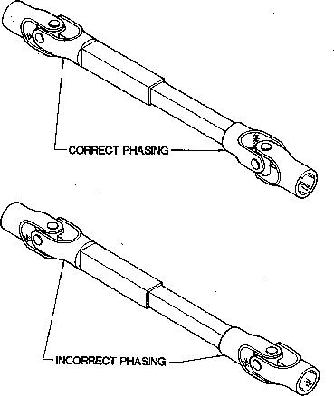
2.4.1 Principles of universal joints
The universal joints in drive shaft are required to be in phase or synchronise when they are fitted to the assembly, this is to ensure that there will be no vibration occur during driving. Universal joint also helps to realize the different direction of output shaft power as it is an important part of the car. In order for this phase to happen is that yokes of u-joints are on the same plane and the universal joint angle has to be parallel. It is also important to point out that when replacing of a u-joint from drive shaft, it is best to mark and index the components before disassembly. Dual universal joints are there for the elimination of Velocity Variation during transfer of power and is useful for vehicles which requires to improve performances (www.sdp-si.com/catalogs/D757Couplings-Universal-Joints3.php). Moreover, it allows the angle between the connected parts changes within a certain range for adaptation and meet the power generated by jumping up and down when the car running changes caused by the angle, front drive cars drive axle, axle shaft is connected to a common universal joint between wheel and axle. A single universal joint cannot make the output shaft and the shaft into the shaft of the instantaneous angular velocity equal and this can easily cause vibration, adding parts damaged, and generate a lot of noise, so hence it is widely used in a variety of patterned for constant speed universal joint (www.cnhws.com).

2.5 Common drive shaft’s component failure
Top components that may likely fail in the event of extensive usage:
Universal Joint (U-joint) – The universal joint is prone to damage can be reflected to long term usage as the part gradually worn, causing some vibrations and abnormal noise might occur in it, which may lessen safety while driving. U-joint is plays an important part in any vehicle, however according to Kang An and Weidan Wang (2017) ‘Transmission performance and fault analysis of a vehicle universal joint’, Advances in Mechanical Engineering, 9(5), pp.1-10, the rotation of the torque transmission is consistent, the direction of the applied stress in the joint is also consistent. After long-term usage, the joint’s shaft journal may have unilateral wear; this can eventually lead to grooves forming on the contact surface of the universal joint, which in turn causes looseness and noise.
Fractured Yoke – A fractured yoke is another common cause of drive shaft failure. Excessive torque and shock loads may cause it. On top of that, a U-joint failure may also cause this component to be worn and damaged quicker.
Fractured Spline – A fractured spline is cause by improper application when it takes in more torque loads that it can handle, the spline on the shaft may worn out quickly. Moreover, having excessive shock loads also causes it to fracture easily. Hence, proper application and periodic maintenance is required for it to operate in smooth working condition.
2.6 Material selection
In this project, it will cover various types of materials to select a material property that is strong and light weight in density. According to Karthikeyan, P. Gobinath, R. Ajith Kumar, L. Xavier Jenish, D (2017) the design and analysis of Kevlar/Epoxy and Glass/Epoxy as a composite material for the drive shaft and by comparing their result with conventional steel drive shaft to find the best replacement for it. The material Steel (SM45C) is a material mostly used for conventional drive shaft which steel material normally satisfy the requirements of torque capacity from transmission, bending natural frequency and capability of buckling torque.
In the case of this project, chosen Steel material which was used is Steel Alloy (SA) which is another common a material used in automotive applications. This material has a composition of Aluminum 0.95-1.30%, Boron, Nickel, Chromium, Vanadium and many others as well as consisting of Manganese of up to 0.4% which helps prevents brittleness in combination with Sulfur and the rest are steel content material (matmatch.com/learn/material/alloy-steel). Although the most appropriate material to use would be Medium Carbon Steel (MCS) for shaft related applications, however, going with what is available in the materials library in the selection process and taking time constraints into account. Hence, the choice was made and nonetheless managed to satisfy the requirements of the torque capacity from the transmission (reliance-foundry.com/blog/carbon-steel-mild-steel). This material has a good combination of other materials to enhance material properties and has shown that it has high fatigue strength, abrasion, impact resistance, toughness, and high torsional strength available (azom.com/article.aspx?ArticleID=6769). Therefore, after much researched the decision on this material can be a good alternative to MCS that is not readily available on the Inventor software.
Chapter 3 – Concept Designs and Selection
3.1 Introduction
The methodology aimed to design a power application drive shaft, it will be using to connect the transmission output to the rear axle differential input. In automotive terms by “propellar shaft” to apply the transfer of rotational torque from the powertrain to the driven wheels. To consolidate methodology aimed at the designing of propellar shaft defines the different stages in order to develop the propellar shaft. Each stages in developing the prop shaft requires a decision and/or method taken:
1. Fishbone Diagram
2. Concept Generation (Client’s Statement)
3. Functional Analysis (FAST Diagram)
4. Morphology Chart
5. Concept Design
6. Weighted Objective Method
3.2 Fishbone Diagram
People
Method
Technical
Unproven Technology Skills required
Fabrication
Miscommunication Automation
Hand build
Changes on the tech
Human error
Improper resource planning
Over budget
Cost cutting
Costs
Cheaper material
Non stainless
Improper material use
Unrealistic goals
Poor Quality Of Propeller Shaft
Material
