Project Portfolio + Resume
Christopher Lam
2024
Project Portfolio + Resume 2024 Christopher Lam
Contact Professional Experience
chris.lam.182@gmail.com
Apt 114
8 Dean Ryle St London SW1P 4DA 0787 339 2436
Software
Rhino 3D
Grasshopper
Adobe Suite
AutoCAD
Twinmotion
Sketchup
Other proficiencies
Physical modelling
CNC
Lasercutting
3D printing
Qualifications note
The University of Toronto M.Arch is a CACB/NCARB accredited professional mutually recognised by the ARB. I am a British citizen with the right to work in the UK.
OAA Intern Architect/Architectural Assistant
Works Office of Brian O’Brian Architect
Assisted in the design of single family dwellings and additions, from strategic definition to technical design
Produced architectural drawings, renders, and models
Researched, developed, and issued zoning and planning applications
Produced tender, budget, and construction drawing sets
Liaised with clients, engineers, contractors, and trades
Architectural Intern
large[medium]designoffice
Assisted in competition research and industrial design work
Produced architectural drawings, models, and videos
Teaching Assistant
University of Toronto
Assisted in graduate and undergraduate courses, including urban planning, site ecology, and technology studios
Led tutorials, critiques, rhino and grasshopper software help, and facilitated online learning spaces through Enscape
Publication Intern
Shim-Sutcliffe, Great Urban Rooms Publication
Conducted archival research of historic Toronto buildings
Curated and arranged architectural drawings and photos
Education
Master of Architecture, M.Arch
University of Toronto
MA Philosophy
University of Bristol
Bachelor of Laws, LLB
Durham University
2021 2015 2013 2019-2021 2021-2023 2019-2021 2018
lairtsudnignisilativeR dnal ot c etaer elcyc fniliarthgildnatsartcur eru c o n n e c t n g t he downtown coretocommunity centre s suburbs, andnational park s R ep urp osing heritagesites to create u rban green spaceand social val ue h u b s gnitaerC biv r a tn , s a fe r s treets t hrough pedestrian a n d cycle priorityzones SD CO SD CO SD CO SD CO SD CO SD CO SD CO 1 FIRST FLOOR PLAN 1/4"=1'-0" PLAN GRAPHICS LEGEND THERMAL INSULATION ACOUSTIC INSULATION LINE ABOVE LINE BELOW (EXCEPTIONS INCLUDE MILLWORK DOOR SWINGS, WHICH ARE SHOWN EXISTING SCHOOLHOUSE LENGTH 38'-1 3/4" FOYER WIDTH 6'-0" F.O. ADDITION TO EXG SCHOOLHOUSE 57'-9 1/8" EXTERIOR ATTACHED SHED 7'-8 3/4" TOTAL BUILDING LENGTH 103'-7 5/8" TOTAL ADDITION LENGTH 65'-5 7/8" OUTSIDE DIMENSION AT ADDITION. THIS DIMENSION INTENDED TO MATCH EXISTING OUTSIDE DIMENSION AT SCHOOLHOUSE 25'-0" CORRIDOR WIDTH 3'-6" EXTERIOR STAIR WIDTH 2'-10" EXTERIOR STAIR: 11" TREADS 10" RUNS MAX 7-3/4" RISE CORRIDOR WIDTH 3'-0" CORRIDOR WIDTH 3'-0" P2 2x4 STAGGERED P3 2x4 P4 2x4 STAGGERED P3 W1 2x6 T A400 2 A400 P2 2x6 2x4 STAGGERED P3 2x4 AS REQ'D PER BEAM MUDROOM WIDTH 3'-6" 2 A300 W1 2x6 D P24 2x6 2x4 STAGGERED UP R DN 1 PRINCIPAL BATHROOM 101A ABBY'S ROOM BEDROOM BATHROOM 104 PRINCIPAL BEDROOM 101 LAUNDRY 105 CORRIDOR 107 POWDER 108 MUDROOM LOUNGE 110 OFFICE OFFICE 111 STORAGE 113 BATHROOM 114 R DN 2 UP UP NEW 1 03 NEW 1 04 NEW 1 05 NEW 06 NEW 07 NEW 1 08 NEW 1 09 NEW 1 10 NEW 1 11 NEW 1 12 1 01 NEW - ABOVE NEW 1 01 NEW 1 02 1 02 NEW - ABOVE NEW 1 13 NEW 1 14 NEW 1 15 NEW 1 16 EXG 1 22 NEW 1 21 NEW 1 20 NEW 1 19 NEW 1 18 NEW 1 17 3 A300 EXTERIOR STAIR WIDTH 2'-10" STAIR WIDTH 3'-0" MECHANICAL ROOM BELOW FOYER R DN 11 1-1/2" DIA CONTINUOUS HANDRAIL AT 34" ABOVE NOSINGS 1-1/2" DIA CONTINUOUS HANDRAIL AT 34" ABOVE NOSINGS SHED 115 NEW 03 LAUNDRY 105: -MILLWORK COUNTER ABOVE APPLIANCES -WASHER AND DRYER -MILLWORK COUNTER W/ BASIN -FLOOR TILE -TILE WAINSCOTING TO 42" AFF -DRYWALL FROM 42" TO CEILING FIRST FLOOR FINISHES UNLESS OTHERWISE NOTED: -3/4" ENGINEERED WHITE OAK FLOORING OVER 4" SLAB W/ HYDRONIC RADIANT HEAT -FLOOR TO CEILING PAINTED DRYWALL -PAINTED DRYWALL CEILING PRINCIPAL BATHROOM 101A: -MILLWORK VANITY -FLOOR TILE -TILE WAINSCOTING TO 42" AFF -DRYWALL FROM 42" TO CEILING -FLOOR TO CEILING TILE AT SHOWER -PAINTED DRYWALL CEILING BATHROOM 104: -MILLWORK VANITY -FLOOR TILE -TILE WAINSCOTING TO 42" AFF -DRYWALL FROM 42" TO CEILING -FLOOR TO CEILING TILE AT SHOWER -PAINTED DRYWALL CEILING FOYER 100 AND MUDROOM 109: -STONE FLOORING OVER 4" SLAB W/ HYDRONIC RADIANT HEATING -FLOOR TO CEILING PAINTED DRYWALL AT NORTH AND SOUTH -FLOOR TO CEILING PAINTED DRYWALL AT STAIR -EXPOSED EXG SCHOOLHOUSE BRICK AT EAST -PAINTED DRYWALL CEILING -FULL HEIGHT MWK CABINETS. SPECIES TBD. BATHROOM 114: -MILLWORK VANITY -FLOOR TILE -TILE WAINSCOTING TO 42" AFF -DRYWALL FROM 42" TO CEILING -FLOOR TO CEILING TILE AT SHOWER -PAINTED DRYWALL CEILING WINE FRIDGE WINE FRIDGE WINE FRIDGE MWK GRAPHICS LEGEND FULL HEIGHT MWK COUNTER HEIGHT MWK SHED 115: -SLAB ON GRADE W/ TURNED DOWN FOOTING -FLOOR TO CEILING VERTICAL SIDING TO MATCH EXTERIOR SIDING -CEILING TO MATCH SOFFIT MATERIAL STAIR: -3/4" ENGINEERED WHITE OAK TREADS -11" TREADS -10" RUNS -MAX 7-3/4" RISE EXISTING ADDITION W1 2x6 D W1 2x6 D OPEN WOOD BURNING FIREPLACE USING RUMFORD PROPORTIONS, RUMFORD THROAT AND STARTER FLUE, AND TRANSITION TO SS CHIMNEY. PLASTER SURROUND AND CAST-IN-PLACE CONCRETE HEARTH FLUSH WITH FLOOR. P2 2x6 2x4 STAGGERED P3 2x4 P3 Contents 207: Cottage in the Shade The Lantern Natatorium Work Life Balance 189: Blue Mountain Schoolhouse Facing Reality Sunken Kindergarten 194: Acropolis Grey Sudbury 2050 Erosion Machines 175: Laneway Suite 4-9 24-31 36-39 10-13 32-35 40-41 20-23 44-45 46-47 14-19
Facing Reality
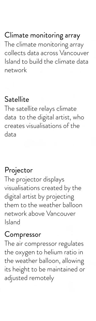
A mobile education and climate monitoring system on Vancouver Island
Site: Vancouver Island, Canada
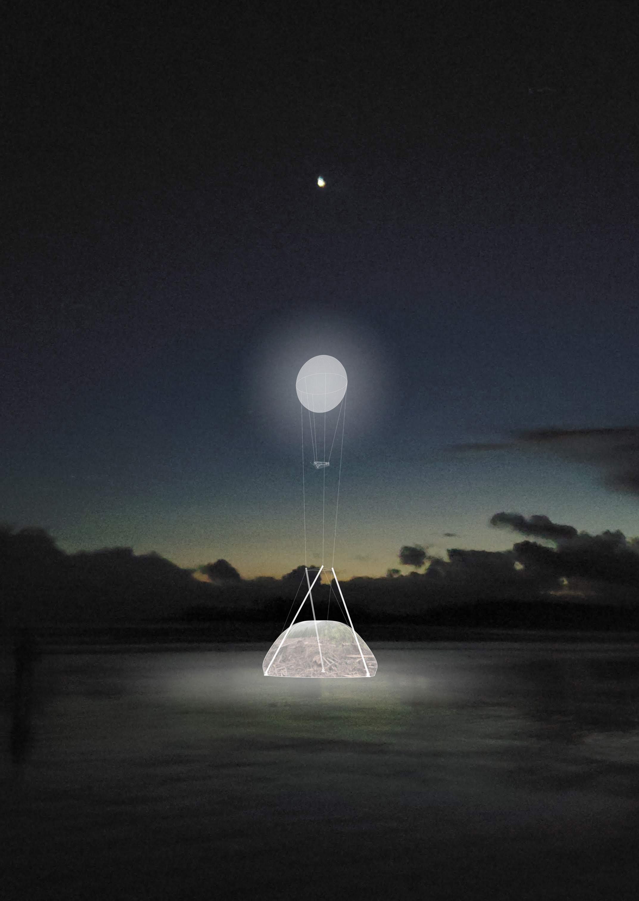
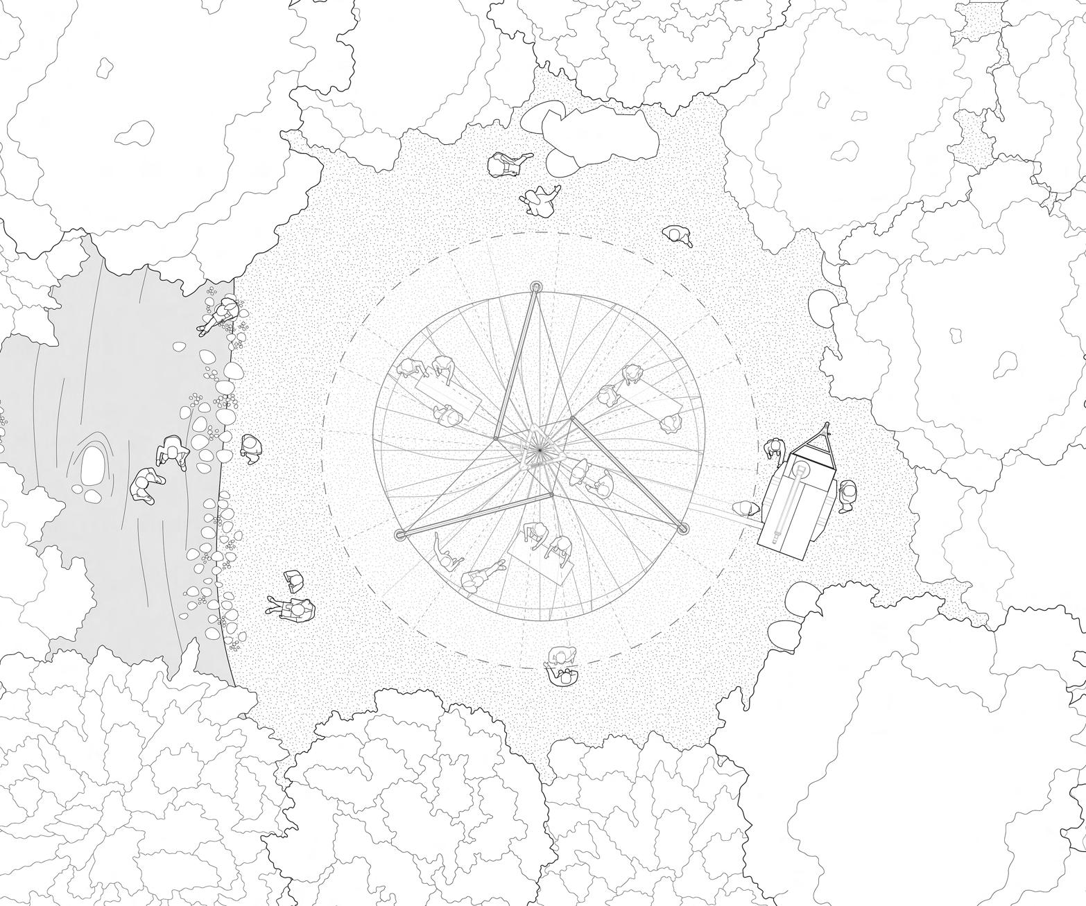
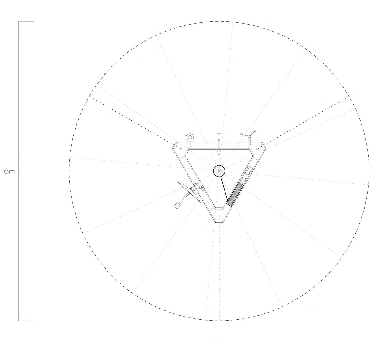
Facing Reality is a mobile climate education centre which attempts to subvert the existing architecture of Vancouver Island’s colonial past in order to address the current climate crisis and establish a network of climate data points. By redefining the architecture of the school in the context of Vancouver Island’s colonial past, the project confronts the colonial ideologies of division, isolation, and permanence. In response to the climate crisis, the mobile school engages with these practices and their effects on Vancouver Island to promote a community driven approach to data collection and to inform a climate education. Its curriculum confronts the reality of climate change in the environment in which we live, as well as reconnecting participants to ecological thought. It strives to create a dialogue between modern science and traditional knowledge, while engaging the public in environmental learning and consciousness.
5
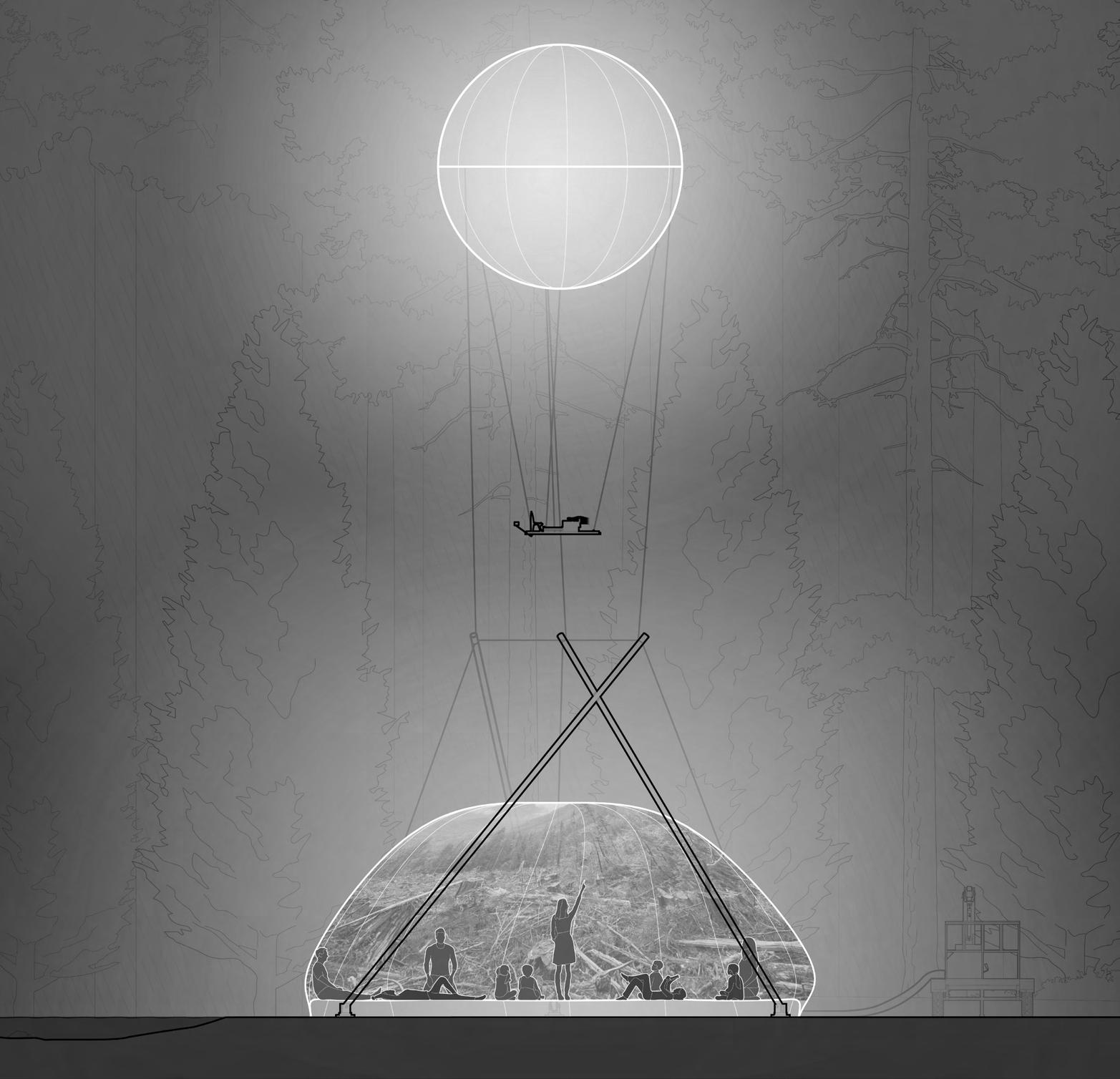
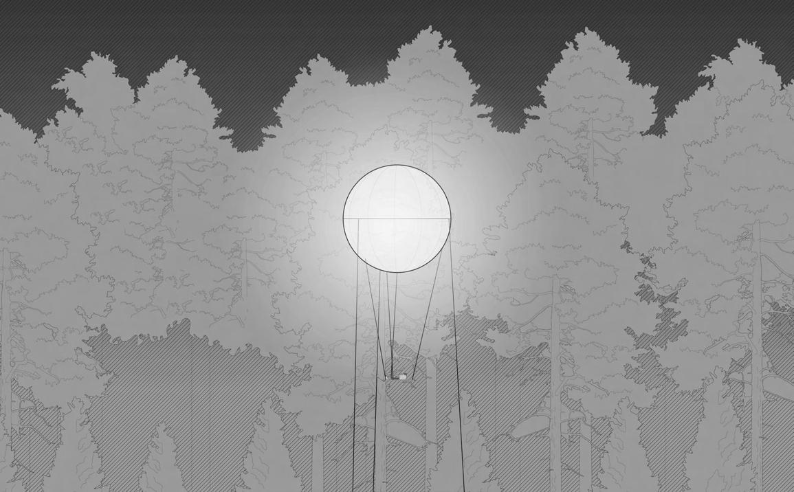
Upon arrival, the climate monitoring balloon is launched and the structure is assembled by the team
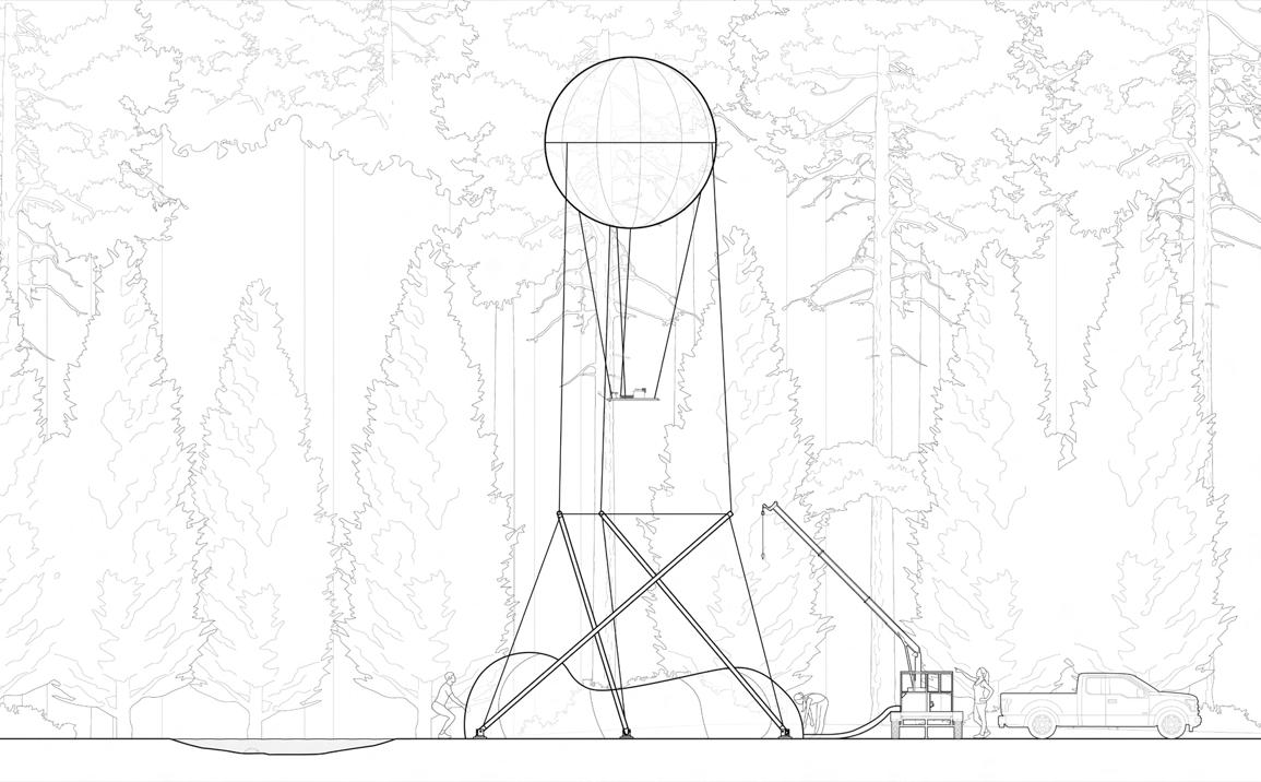
As participants begin to gather, the pneumatic structure is inflated. It will host field courses, lectures, and evening stories and films
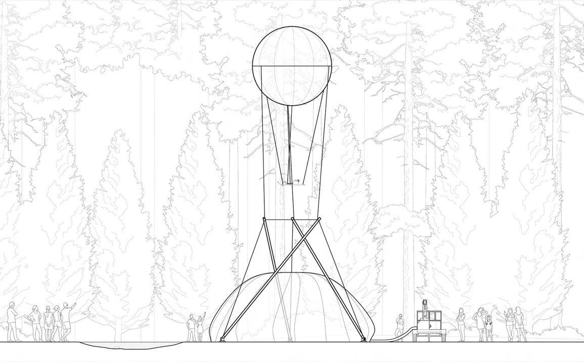
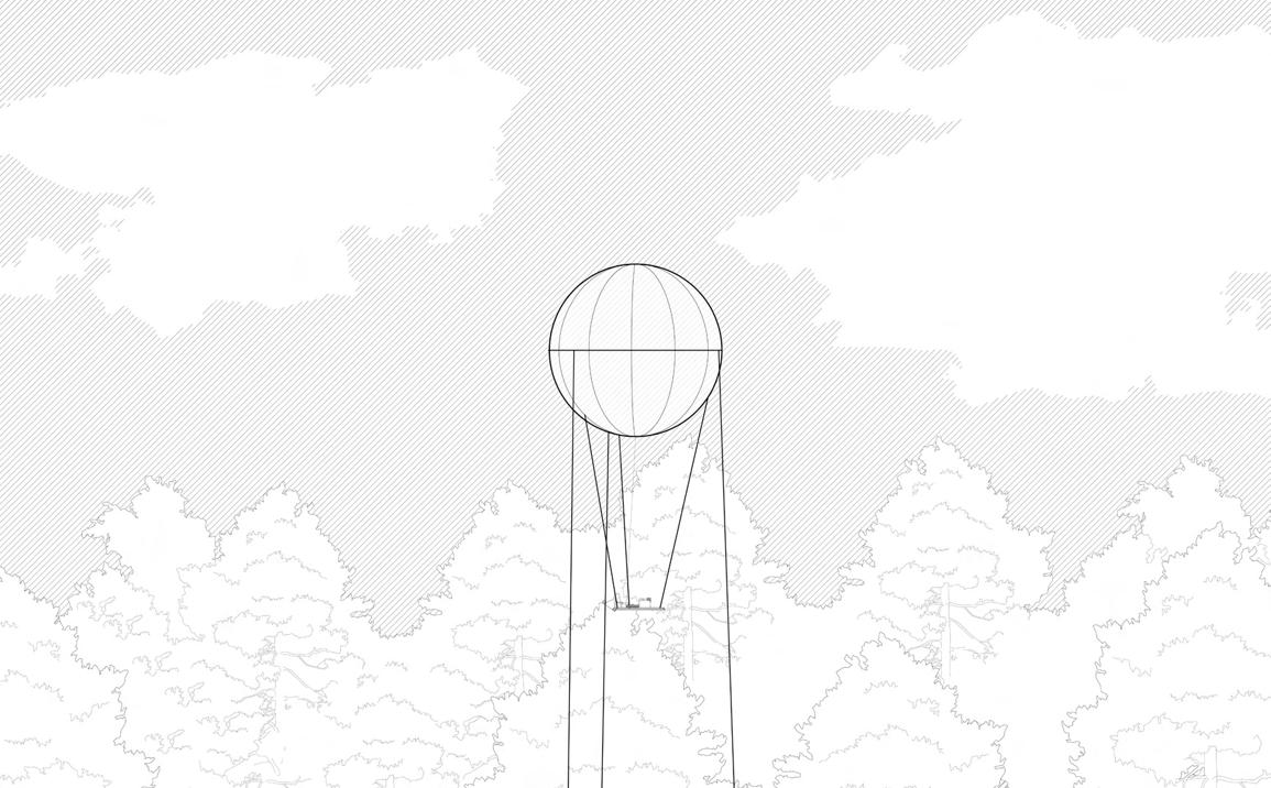
The climate monitoring balloon is raised above the tree line to collect data. After the event is finished, it will remain and be raised again to continue monitoring
6
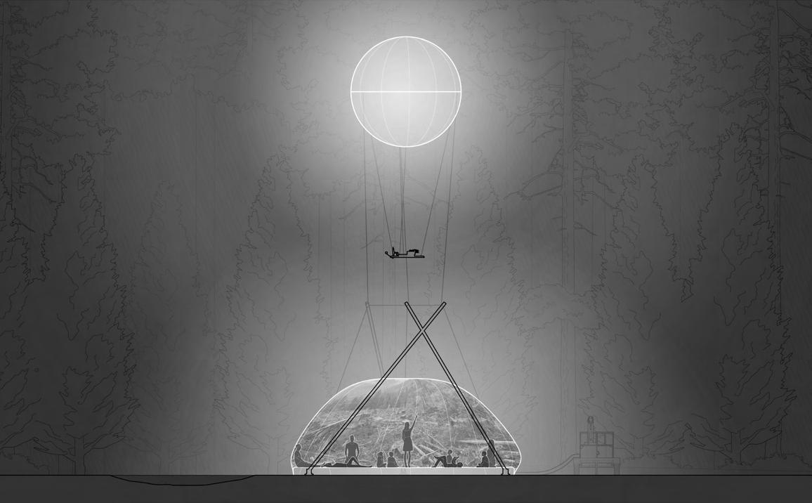
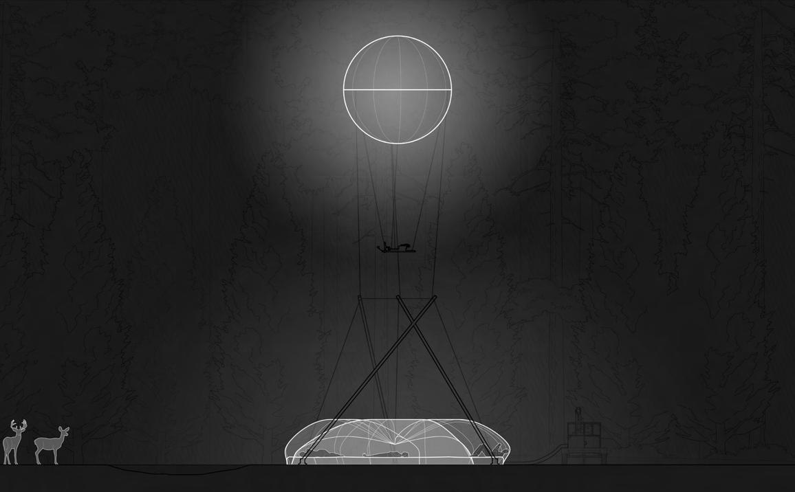
In the evenings, the climate monitoring balloon is lowered to signal the start of the evening activities and to provide light to the inflatable below
The inflatable structure can be used as the backdrop for films, lectures, and seminars, as well as traditional storytelling
At night, the structure is deformed with straps to create private spaces for the teachers and scientists to sleep
7
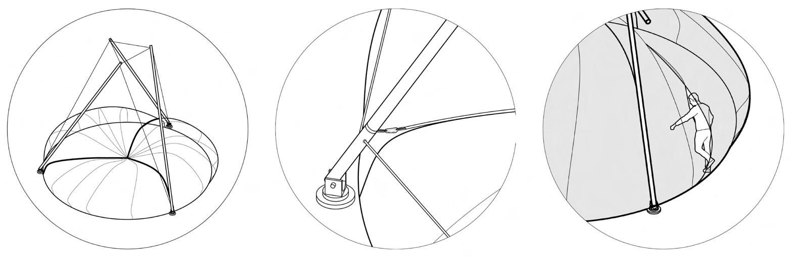
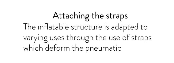
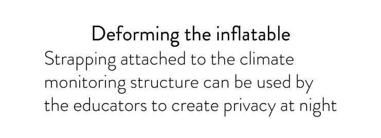
8
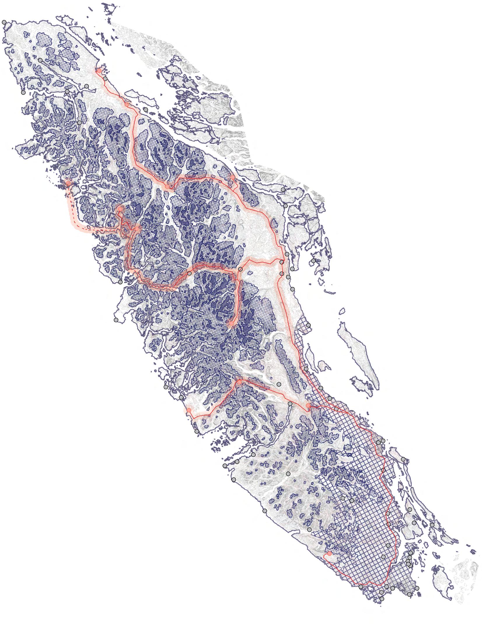
GIS data was compiled to identify climate zones, road and waterways, and settlements on Vancouver Island. This data, combined with an analysis of current gaps in the current climate monitoring network, was then used to plot a course for the mobile education and climate monitoring system.
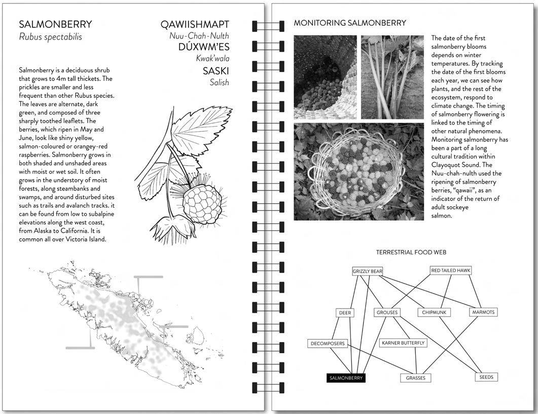
This data is also used to inform the Climate Curriculum, which uses bio-indicators on Vancouver Island linked to corresponding climate zones. This participatory curriculum creates new data points for climate monitoring as well as encouraging engagement from citizen scientists.
9 Climate education field guide
189: Blue Mountain Schoolhouse
Site: Blue Mountain, Ontario Works Office of Brian O’Brian Architect
The Blue Mountain Schoolhouse project consists of an extension to a 19th century brick schoolhouse, as well as surrounding lanscaping, including septic work and a relocated driveway.
The schematic design takes the profile of the schoolhouse as a start point to begin shaping the addition. This form is then freely manipulated to reflect its purposes: pulled to create length, raised to provide height for the upper public and lower private areas, and sliced to orient views to the mountain.
“There is a closed formality in a building like the Schoolhouse. What is critical is recognizing that formality in a way that allows us to respect its hierarchy as a starting point for the Work while also permitting a new piece of architecture that is equally not subservient to it.”
10
RICINSET DRAINSTATUS DATE STRUCTURAENINEER IEFFERSTRUCTURAENINEERIN ERRARDSTREETEAST TORONTOONACANADA IEFFERCA ECHANICA AACONSUTIN OFFICE DRAN SCHOOHOUSEUE THEUEOUNTAINSCEARIE TONINE THEUEOUNTAINSONR A SITEANAND CONTOURA 1 SITE PLAN 262.75m 262.99m 262.88m 262.80m 262.91m 263.30m 263.07m CONTINUOUS FRENCH DRAIN EXTEND FRENCH DRAIN WEEPING TILE TO DISCHARGE AT DITCH. TRANSFER FROM PERFORATED TO SOLID PIPE AT SEPTIC BED AREA. SEPTIC BED AND FIELD. REFER TO NOTES REGARDING THE GENERATION OF THIS DOCUMENT ALL PROPERTY LINES AND BUILDING LOCATION DIMENSIONS ARE EXTRAPOLATED FROM ZEPT ONTARIO LAND SURVEYORS SURVEY TENDERED 15 SEPTEMBER, 2021. ALL SPOT ELEVATION AND CONTOURS ARE EXTRAPOLATED FROM ZEPT ONTARIO LAND SURVEYORS SURVEY TENDERED 15 SEPTEMBER, 2021 AND TATHAM ENGINEERING SEWAGE SYSTEM PLANS DATED MARCH 2023. DIMENSIONS, PRECISION IS NOT GUARANTEED. CONTOURS ARE SHOWN IN 6" INTERVALS. EXISTING GRADING RELOCATED GRADING PERMEABLE PAVING BRIDGE SEPTIC TANKS. REFER TO SEPTIC PLAN BY TATHAM ENGINEERING FOR SPECIFICS EXG TREE
11 CO SD SD SD SD SD CO SD RICINSET DRAINSTATUS DATE ISSUESANDREISIONS STRUCTURAENINEER IEFFERSTRUCTURAENINEERIN ERRARDSTREETEAST TORONTOONACANADA OFFICE IEFFERCA ECHANICA AACONSUTIN CHECED SCHOOHOUSEUE THEUEOUNTAINSONR 1 FIRST FLOOR PLAN 1/4"=1'-0" AA FIRSTFOOR AN PLAN GRAPHICS LEGEND LINE ABOVE DOOR SWINGS, WHICH ARE SHOWN SIMILARLY) EXISTING SCHOOLHOUSE LENGTH 38'-1 3/4" FOYER WIDTH 6'-0" F.O. ADDITION TO EXG SCHOOLHOUSE 57'-9 1/8" EXTERIOR ATTACHED SHED 7'-8 3/4" 103'-7 5/8" TOTAL ADDITION LENGTH 65'-5 7/8" OUTSIDE DIMENSION AT ADDITION. THIS DIMENSION INTENDED TO MATCH EXISTING OUTSIDE DIMENSION AT SCHOOLHOUSE 25'-0" CORRIDOR WIDTH 3'-6" EXTERIOR STAIR WIDTH 2'-10" EXTERIOR STAIR: 11" TREADS 10" RUNS MAX 7-3/4" RISE CORRIDOR WIDTH 3'-0" CORRIDOR WIDTH 3'-0" P2 2x6 P3 2x4 STAGGERED P3 W1 2x6 1 2 A401 A401 P2 2x6 2x4 STAGGERED P3 2x4 AS REQ'D PER BEAM MUDROOM WIDTH 3'-6" 1 W1 2x4 STAGGERED UP R DN 1 PRINCIPAL BATHROOM 101A 102 103 BATHROOM 104 PRINCIPAL BEDROOM LAUNDRY 105 107 POWDER 108 MUDROOM 109 LOUNGE 110 112 111 STORAGE 113 BATHROOM 114 DN UP UP 03 04 05 NEW 06 NEW 1 07 08 09 NEW 10 NEW 11 12 01 NEW ABOVE NEW 01 NEW 02 1 02 NEW ABOVE 13 14 15 16 22 21 20 NEW 1 19 1 18 17 3 EXTERIOR STAIR WIDTH 2'-10" STAIR WIDTH 3'-0" MECHANICAL ROOM BELOW FOYER 100 R DN 11 1-1/2" DIA CONTINUOUS HANDRAIL AT 34" ABOVE 1-1/2" DIA CONTINUOUS HANDRAIL AT 34" ABOVE NOSINGS 115 NEW 03 -MILLWORK COUNTER ABOVE APPLIANCES -WASHER AND DRYER -MILLWORK COUNTER W/ BASIN -FLOOR TILE -TILE WAINSCOTING TO 42" AFF -PAINTED DRYWALL CEILING -3/4" ENGINEERED WHITE OAK FLOORING OVER 4" SLAB W/ HYDRONIC RADIANT HEAT -FLOOR TO CEILING PAINTED DRYWALL -PAINTED DRYWALL CEILING PRINCIPAL BATHROOM 101A: -MILLWORK VANITY -FLOOR TILE -TILE WAINSCOTING TO 42" AFF -FLOOR TO CEILING TILE AT SHOWER -PAINTED DRYWALL CEILING -MILLWORK VANITY -FLOOR TILE -TILE WAINSCOTING TO 42" AFF -DRYWALL FROM 42" TO CEILING -PAINTED DRYWALL CEILING FOYER 100 AND MUDROOM 109: -STONE FLOORING OVER 4" SLAB W/ HYDRONIC RADIANT HEATING -FLOOR TO CEILING PAINTED DRYWALL AT NORTH -EXPOSED EXG SCHOOLHOUSE BRICK AT EAST -PAINTED DRYWALL CEILING -FULL HEIGHT MWK CABINETS. SPECIES TBD. -MILLWORK VANITY -FLOOR TILE -TILE WAINSCOTING TO 42" AFF -DRYWALL FROM 42" TO CEILING -PAINTED DRYWALL CEILING WINE FRIDGE FRIDGE MWK GRAPHICS LEGEND SHED 115: -SLAB ON GRADE W/ TURNED DOWN FOOTING -FLOOR TO CEILING VERTICAL SIDING TO MATCH EXTERIOR SIDING -3/4" ENGINEERED WHITE OAK TREADS -11" TREADS -10" RUNS -MAX 7-3/4" RISE EXISTING ADDITION W1 W1 2x6 OPEN WOOD BURNING FIREPLACE USING RUMFORD PROPORTIONS, RUMFORD THROAT AND STARTER FLUE, AND TRANSITION TO SS CHIMNEY. PLASTER CONCRETE HEARTH FLUSH WITH FLOOR. 2x6 2x4 STAGGERED P3 2x4 SD RICINSET DRAINSTATUS DATE STRUCTURAENINEER IEFFERSTRUCTURAENINEERIN ERRARDSTREETEAST TORONTOONACANADA OFFICE ECHANICA AACONSUTIN OFFICE DRAN CHECED SCHOOHOUSEUE THEUEOUNTAINSCEARIE TONINE THEUEOUNTAINSONR PLAN GRAPHICS LEGEND THERMAL INSULATION ACOUSTIC INSULATION LINE BELOW (EXCEPTIONS INCLUDE MILLWORK DN 16 AA SECONDFOOR AN 1 SECOND FLOOR PLAN LIVING RM DINING RM KITCHEN NEW 2 NEW NEW 1 NEW 1 NEW 2 38'-1 3/4" TOTAL BUILDING LENGTH 103'-7 5/8" OUTSIDE DIMENSION AT ADDITION. THIS DIMENSION INTENDED TO MATCH EXISTING OUTSIDE DIMENSION AT SCHOOLHOUSE 25'-0" CORRIDOR WIDTH 3'-0" NEW 07 NEW ABOVE 2 03 05 NEW 2 2 04 NEW 2 204 3'-0" TOTAL ADDITION LENGTH 65'-5 7/8" 2'-10" 2x6 D DECK OVERHANG *8'-1 1/2" A401 A401 A300 DN 15 1 A400 A400 A300 A300 STAIR: -3/4" ENGINEERED WHITE OAK TREADS -10" RUNS -MAX 7-3/4" RISE 11" TREADS 10" RUNS MAX 7-3/4" RISE SITTING NOOK 206 W1 2x6 SECOND FLOOR FINISHES UNLESS OTHERWISE NOTED: -3/4" ENGINEERED WHITE OAK FLOORING W/ THERMALBOARD RADIANT HEATING -PAINTED DRYWALL CEILING MWK GRAPHICS LEGEND FULL HEIGHT MWK 57'-9 7/8" EXISTING ADDITION DECK 204 AND SITTING NOOK 205: -5/4" PORCELAIN PAVER BY MARBLETREND OR APPROVED OTHER HEATIZON PEDESTAL PAVER SNOW MELTING SYSTEM -DENSDECK ROOF BOARD -WOOD AND STEEL FRAMING PER STRUCTURAL -WOOD SOFFIT. SPECIES TBD. 2x6 D OPEN WOOD BURNING FIREPLACE USING RUMFORD PROPORTIONS, RUMFORD THROAT AND STARTER FLUE, AND TRANSITION TO SS CHIMNEY. BRICK SURROUND AND CAST-IN-PLACE CONCRETE HEARTH.
plan
plan Left: Site plan
Top: Ground floor
Bottom: First floor
12 +26'-7 1/2"T.O. ROOF RIDGE 27'-0"MAXIMUM HEIGHT PER OSLER SKI CLUB LICENSE TO CONSTRUCT +17'-3 1/4" ADDITION SPRINGPOINT +26'-7 1/2"T.O. ROOF RIDGE +24'-7 1/4"UNDERSIDE ADDITION CEILING +17'-3 1/4" ADDITION SPRINGPOINT RICIN DRAINSTATUS DATE ISSUES AND STRUCTURA IEFFER ERRARD TORONTO IEFFERCA ECHANICA AA CONSUTIN OFFICE DRAN SCHOOHOUSE THE THE UE A NORTH EEATIONS 2 NORTH ELEVATION 1 SOUTH ELEVATION EXISTINGADDITION 9'-5 5/8" 3'-3 1/2" 5'-2 1/2" 3'-3 1/2" 5'-2 1/2" 3'-3 1/2" 3'-3 1/2" 3'-3 1/2" 3'-3 1/2" 6'-0" 6'-0" 5'-7" 5'-0" 4'-11 1/2" 5'-8 1/2" 1'-11 1/2" 2'-0 1/4" 3'-0 1/2" 15'-2 3/8" 2'-0" 12'-10 1/8" 8'-7 1/8" 11" 8'-7 1/8" 11'-4 1/8" 6'-0" 5'-7" 3'-3 1/2" 5'-0" 3'-3 1/2" 4'-11 1/2" 3'-3 1/2" 5'-8 1/2" 1'-11 1/2" 2'-0 1/4" 3'-0 1/2" MATCH EXG IN DIMENSION AND PROFILE. INCLUDE: REINSTALL EXG BELL. NEW STEEL ROOFING TO MATCH NEW ROOFING AT ADDITION. GENERAL NOTES 01 CONCEALED FASTENERS. COLOUR TBD. 09 RECONSTRUCTED CUPOLA 02 PAINTED OR SEALED WOOD TRIM AT EXG BRICK 10 1/4" THK x 2"W POWDER COATED STEEL GUARDRAIL PICKETS AND CAP 03 BOARD 11 EXISTING BRICK. CLEAN AND TUCKPOINT AS REQD 04 SS FLUE. TIE DOWN AS REQD 12 W3 06 BLACKENED VERTICAL SIDING AT ALTERNATE 14 SOFFIT. MATCH SIDING 07 WINDOW DOOR UNIT 15 BRICK FILL SET FLUSH W/ ADJ MASONRY 08 THIS TAG NOT USED 6 15 6'-8" 1'-5 1/2" *8'-11" 6'-2 3/4" 4'-4" 5'-8" 7'-0" *1'-9" *11'-5" *5'-3" 5'-8" 12 8'-7 107/128" 14'-1 1/4" *17'-0 1/2" *5'-3" 5'-8" 6'-2 3/4" 4'-4" 8'-4 1/4" *4'-1 3/4" 8'-4 1/4" *4'-1 3/4" +8'-6 1/2"T.O. SECOND FLOOR FINISH -2'-7 1/4" VIFT.O. SCHOOLHOUSE FIRST FLOOR FINISH +28'-7"T.O. CHIMNEYS +26'-7 1/2"T.O. ROOF RIDGE +17'-3 1/4" ADDITION SPRINGPOINT RICINSET DRAINSTATUS DATE ISSUESANDREISIONS STRUCTURAENINEER IEFFERSTRUCTURAENINEERIN ERRARDSTREETEAST TORONTOONACANADA IEFFERCA ECANICA AACONSUTIN OFFICE DRAN SCOOOUSEUE TEUEOUNTAINSCEARIE TONINE TEUEOUNTAINSONR A SECTIONS 1 EAST-WEST LONGITUDINAL SECTION 1/4"=1'-0" 2 NORTH-SOUTH TRANSVERSE SECTION A 3 NORTH-SOUTH TRANSVERSE SECTION B R1 D SEE STRUCTURAL W3 D SEE STRUCTURAL R1 D SEE STRUCTURAL R1 D SEE STRUCTURAL G3 G1 G2 SEE STRUCTURAL SEE STRUCTURAL F1 D SEE STRUCTURAL R1 SEE STRUCTURAL D OUTSIDE DIMENSION AT ADDITION. THIS DIMENSION INTENDED TO MATCH EXISTING OUTSIDE DIMENSION AT SCHOOLHOUSE 25'-0" 1'-0" 1'-0" 4'-11 1/2" 2'-0 1/4" FOYER F.F. TO SPRINGPOINT VIF *18'-8 1/2" FOYER F.F. TO CEILING RIDGE VIF *26'-1" FIRST FLOOR F.F. TO UNDERSIDE CEILING 9'-0" 1'-7 1/2" SEDOND FLOOR F.F. TO SPRINGPOINT VIF *8'-8 1/2" SECOND FLOOR F.F. TO CEILING RIDGE VIF *16'-1" OUTSIDE DIMENSION AT ADDITION. THIS DIMENSION INTENDED TO MATCH EXISTING OUTSIDE DIMENSION AT SCHOOLHOUSE 25'-0" 1'-0" 1'-0" 12" 3/4" VIF +8'-6 1/2"T.O. SECOND FLOOR FINISH -2'-7 1/4" VIFT.O. SCHOOLHOUSE FIRST FLOOR FINISH +17'-2 3/4"UNDERSIDE EXG CEILING +28'-7"T.O. CHIMNEYS VERTICAL START POINT ESTABLISHED GRADE -2'-0 3/4"T.O. FIRST FLOOR FINISH +24'-7 1/4"UNDERSIDE ADDITION CEILING +17'-5 1/2" UNDERSIDE OF EAVES RICINSET DRAINSTATUS DATE ISSUESANDREISIONS STRUCTURAENINEER IEFFERSTRUCTURAENINEERIN ERRARDSTREETEAST TORONTOONACANADA OFFICE IEFFERCA ECANICA AACONSUTIN OFFICE DRAN CECED SCOOOUSEUE TEUEOUNTAINSCEARIE TEUEOUNTAINSONR A SECTIONS 1 EAST-WEST LONGITUDINAL SECTION 1/4"=1'-0" 2 NORTH-SOUTH TRANSVERSE SECTION A 1/4"=1'-0" 3 NORTH-SOUTH TRANSVERSE SECTION B 1/4"=1'-0" R1 D SEE STRUCTURAL W3 2x4 D SEE STRUCTURAL R1 SEE STRUCTURAL R1 D SEE STRUCTURAL G3 G1 G2 SEE STRUCTURAL G2 SEE STRUCTURAL F1 D SEE STRUCTURAL R1 SEE STRUCTURAL D OUTSIDE DIMENSION AT ADDITION. THIS DIMENSION INTENDED TO MATCH EXISTING OUTSIDE DIMENSION AT SCHOOLHOUSE 25'-0" 1'-0" 1'-0" 4'-11 1/2"2'-0 1/4" FOYER F.F. TO SPRINGPOINT VIF *18'-8 1/2" FOYER F.F. TO CEILING RIDGE VIF *26'-1" FIRST FLOOR F.F. TO UNDERSIDE CEILING 9'-0" 1'-7 1/2" SEDOND FLOOR F.F. TO SPRINGPOINT VIF *8'-8 1/2" SECOND FLOOR F.F. TO CEILING RIDGE VIF *16'-1" OUTSIDE DIMENSION AT ADDITION. THIS DIMENSION INTENDED TO MATCH EXISTING OUTSIDE DIMENSION AT SCHOOLHOUSE 25'-0" 1'-0" 1'-0" 3/4" VIF
Clockwise, from top left: South elevation, North elevation, Assemblies, Transverse sections, Longitudinal section
The Blue Mountain Schoolhouse joins the 19th century schoolhouse to the proposed addition with a double height breezeway. The addition is clad in blackened hemlock to contrast the existing red brick of the schoolhouse. A standing seam steel roof unites the two pieces, lifting upward in stages.
13 -2'-7 1/4" VIFT.O. SCHOOLHOUSE FIRST FLOOR FINISH +26'-7 1/2"T.O. ROOF RIDGE 27'-0"MAXIMUM HEIGHT PER OSLER SKI CLUB LICENSE TO CONSTRUCT +17'-3 1/4" ADDITION SPRINGPOINT RICIN DRAINSTATUS DATE DRAN SCHOOHOUSE THE TONINE THE UE A NORTH EEATIONS 2 NORTH ELEVATION 1 SOUTH ELEVATION 1/4"=1'-0" EXISTINGADDITION 9'-5 5/8" 3'-3 1/2" 5'-2 1/2" 3'-3 1/2" 5'-2 1/2" 3'-3 1/2" 3'-3 1/2" 3'-3 1/2" 3'-3 1/2" 6'-0" 6'-0" 5'-7" 5'-0" 4'-11 1/2" 5'-8 1/2" 1'-11 1/2"2'-0 1/4"3'-0 1/2" 15'-2 3/8" 2'-0" 12'-10 1/8" 8'-7 1/8" 11" 8'-7 1/8" 11'-4 1/8" 6'-0" 5'-7" 3'-3 1/2" 5'-0" 3'-3 1/2" 4'-11 1/2" 3'-3 1/2" 5'-8 1/2" 1'-11 1/2" 2'-0 1/4" 3'-0 1/2" GENERAL NOTES 01 STEEL ROOFING: VICWEST PRESTIGE 16 WITH 09 RECONSTRUCTED CUPOLA 02 PAINTED OR SEALED WOOD TRIM AT EXG BRICK 10 1/4" THK x 2"W POWDER COATED STEEL GUARDRAIL 03 VICWEST STEEL FLASHING ON SEALED WD FASCIA 11 EXISTING BRICK. CLEAN AND TUCKPOINT AS REQD 04 SS FLUE. TIE DOWN AS REQD 12 POLYCARBONATE WALL. REFER TO A007 ASSEMBLY 05 BLACKENED VERTICAL SIDING 13 SNOW GUARD BLACKENED VERTICAL SIDING AT ALTERNATE SPACING AT WINDOWS 07 WINDOW DOOR UNIT 15 BRICK FILL SET FLUSH W/ ADJ MASONRY THIS TAG NOT USED 6 15 *5'-3" 5'-8" 12 8'-7 107/128" 14'-1 1/4" *5'-3" 5'-8" 6'-2 3/4" 4'-4" 8'-4 1/4" *4'-1 3/4" ASSEMBLY SHALL BE READ IN CONJUNCTION WITH ASSEMBLY NOTES, CONTRACT SPECIFICATIONS, AND MANUFACTURER'S CONSTRUED IN SUCH A WAY AS TO CONTRAVENE MANUFACTURER'S WARRANTIES. FOR PLAN VIEW, READ ASSEMBLY FROM LEFT TO RIGHT FOR SECTION VIEW, READ ASSEMBLY FROM TOP TO BOTTOM TOP BOTTOM 1-1/2" = 1'-0" 1 FLOOR ASSEMBLIES ASSEMBLY NOTES. READ IN CONJUNCTION WITH ASSEMBLY DETAILS REFERENCE "REF" IN ASSEMBLY DETAILS REFERS TO FIRE RESISTANCE RATINGS AND SOUND TRANSMISSION CLASS. REFERENCE PROVIDED IS DERIVED FROM SOURCES SUCH AS OBC SB-2, OBC SB-3, GYPSUM ASSOCIATION, UNDERWRITERS LABORATORY, ETC AS INDICATED IN THE ASSEMBLY. "NA" ONLY MEANS THERE IS NO DEFINITION PROVIDED IN THIS DETAIL. THIS DOES NOT MEAN THIS CALCULATED A. MATERIALS 1.1.ALL DRYWALL AT WET LOCATIONS, INCLUDING BUT LIMITED TO THE FOLLOWING, SHALL BE GEORGIA PACIFIC MMR OR APPROVED EQUAL: 1.1.1.ALL WET ROOM WALLS AND CEILINGS, INCLUDING BATHROOMS, POWDER ROOMS, KITCHENS AND UTILITY ROOMS 1.1.2.SKYLIGHT ENCLOSURES TO MINIMUM 36" VERTICALLY BELOW T.O. UPPERMOST EDGE OF DRYWALL 1.1.3.KITCHEN WALLS WHERE DRYWALL IS ADJACENT TO COUNTER SURFACES, AND TO A MINIMUM HEIGHT OF 24" ABOVE COUNTERTOP 2.WOOD, TILE, AND OTHER FINISH MATERIALS: THICKNESS INDICATED IS TYPICAL. ACTUAL THICKNESS MAY VARY. REFER TO FINISH SCHEDULE AND ELEVATIONS FOR SPECIFICATION, INCLUDING THICKNESS, FINISH, DIMENSIONS, AND LAYOUT. WHERE TILE IS INDICATED, INSTALL 1/2" CEMENTITIOUS BOARD IF APPLICABLE. WHERE WOOD FINISH MATERIAL IS INDICATED, IF BOARDS ARE NOT T&G, INSTALL BLACK FELT ON FRAMING PRIOR TO INSTALLING WOOD BOARDS VENEER TIES AT MAX EVERY (6) COURSES VERTICALLY 4.STEEL SIDING AND ROOFING: 3/4" PROFILE DEPTH IS INDICATED. ACTUAL DEPTH MAY VARY. REFER TO FINISH SCHEDULE AND ELEVATIONS FOR PROFILE SPECIFICATION AND LAYOUT 5.SHINGLES: REFER TO FINISH SCHEDULE FOR SPECIFICATION 6.FINISHED CONCRETE: DENSIFY, GRIND AND POLISH 8.POLYCARBONATE PANELS SHALL BE 5/8" (16MM) THICK BY POLYGAL INC. ENDS SHALL BE CAPPED WITH VENTING TAPE AND U-PROFILE AS PER MANUFACTURER'S INSTRUCTIONS. BACK SIDE OF ENTIRE PERIMETER OF EACH PANEL SHALL BE SEALED WITH CLEAR SILICONE PRIOR TO INSTALLATION. DO NOT SEAL CAVITIES. CELLS MUST BE ALLOWED TO WEEP. REFER TO MANUFACTURER'S INSTRUCTIONS. 9.TYPE GLASS MAT GYPSUM PRODUCTS SHALL BE GP DENSGLASS GOLD FIREGUARD, CERTAINTEED GLASROC SHEATHING, OR SIMILAR B. MATERIAL DESIGNATIONS 1. WHERE INDICATED: EXISTING MATERIAL EXISTS THIS LOCATION 2. WHERE INDICATED: 5/8" TYPE X DRYWALL. SEE NOTE A1 3. WHERE INDICATED: 1/8" THINSET WITH 3/8" TILE. SEE NOTE A2 4. WHERE INDICATED: 3/4" VERTICAL WOOD BOARDS. SEE NOTE A2 5. WHERE INDICATED: 3/4" HORIZONTAL WOOD BOARDS. SEE NOTE A2 6. WHERE INDICATED: 1/2" PLYWOOD. SEE NOTE A2 7. WHERE INDICATED: 3/4" WOOD FLOORING. SEE NOTE A2 8. WHERE INDICATED: 1/8" MARMOLEUM. SEE NOTE A2 9. WHERE INDICATED: 1/4" RUBBER. SEE NOTE A2 10. WHERE INDICATED: 3/4" STEEL. SEE NOTE A4 11. WHERE INDICATED: 3/4" CARPET ON 1/4" PAD. SEE NOTE A2 12. WHERE INDICATED: REFER SPECIFICALLY TO DETAILS C. STRUCTURAL 1.WHERE SHEAR WALL IS INDICATED, REFER TO STRUCTURAL DRAWINGS FOR SHEAR REQUIREMENTS AIR, WATER AND VAPOUR CONTROL 1.1.1/4" +/- STUCCO FINISH 1.2.IMPACT RESISTANT MESH 1.3.VAPOUR PERMEABLE INSULATION PER ASSEMBLY SPECIFICATION 1.4.VAPOUR PERMEABLE AIR AND WATER BARRIER 2.AIR AND WATER BARRIER (AWB) SHALL BE VAPOUR PERMEABLE. MAINTAIN CONTINUITY 3.AIR, WATER AND VAPOUR BARRIER SHALL BE VAPOUR IMPERMEABLE. MAINTAIN CONTINUITY 4.WHERE MODIFIED BITUMEN IS INDICATED, INSTALL WHITE OR GREY MEMBRANE. DO NOT INSTALL BLACK MATERIAL 5.VAPOUR BARRIER SHALL BE VAPOUR IMPERMEABLE. MAINTAIN CONTINUITY 6.FOR STEEL ROOFING SLOPES OF 3:12 AND LESS, VAPOUR PERMEABLE GRACE ICE AND WATER SHIELD SHALL BE INSTALLED BELOW PLUMBING 1.CONTRACTOR SHALL ENSURE ORGANIZED AND ADEQUATE PIPE LAYOUT IN CONFORMANCE WITH HEAT LOSS CALCULATIONS 2.PANEL INDICATED IS REHAU RAU PANEL WITH RADIANT PIPE. RAU PANEL OR WARMBOARD ARE ACCEPTABLE. CONTRACTOR SHALL ENSURE ORGANIZED AND ADEQUATE PIPE LAYOUT SIPS (STRUCTURAL INSULATED PANELS) G. INSULATION 1.WHERE XPS IS INDICATED, EPS IS PERMISSIBLE PROVIDED THE SPECIFIED R VALUE IS ACHIEVED, AND THE MATERIAL CONFORMS TO A PERM RATING BETWEEN 1.0 AND 10.0 3/4" SPF HORIZONTAL STRAPPING ON 3/4" VERTICAL SPF STRAPPING AT EA STUD 2x6 WOOD FRAMING AT MAX 16" O.C. FILL CAVITIES WITH ROCKWOOL COMFORTBATT INSULATION AT VALUE INDICATED 1/2" PLYWOOD SHEATHING 1-1/4" ROCKWOOL RIGID INSULATION AT R5 ASSEMBLY SHALL BE READ IN CONJUNCTION WITH ASSEMBLY NOTES, CONTRACT SPECIFICATIONS, AND MANUFACTURER'S CONSTRUED IN SUCH A WAY AS TO CONTRAVENE MANUFACTURER'S WARRANTIES. FOR PLAN VIEW, READ ASSEMBLY FROM LEFT TO RIGHT FOR SECTION VIEW, READ ASSEMBLY FROM TOP TO BOTTOM 1-1/2" = 1'-0" FILL CAVITIES WITH ROCKWOOL ACOUSTIC INSULATION 5/8" DRYWALL. SEE NOTE A1 5/8" DRYWALL. SEE NOTE A1 ASSEMBLY TYPE: DRAWING VIEW: VALUE: FRR: STC: REFERENCE: ASSEMBLY SHALL BE READ IN CONJUNCTION WITH ASSEMBLY NOTES, CONTRACT SPECIFICATIONS, AND MANUFACTURER'S CONSTRUED IN SUCH A WAY AS TO CONTRAVENE MANUFACTURER'S WARRANTIES. FOR PLAN VIEW, READ ASSEMBLY FROM LEFT TO RIGHT FOR SECTION VIEW, READ ASSEMBLY FROM TOP TO BOTTOM SCALE: P2 DRYWALL PLAN NA NA NA NA 1-1/2" = 1'-0" STAGGERED 2x4 WOOD FRAMING AT MAX 16" O.C. EA SIDE. SET ON 2x6 PLATE FILL CAVITIES WITH ROCKWOOL ACOUSTIC INSULATION 5/8" DRYWALL. SEE NOTE A1 WOOD FRAMING PER PLANS AT MAX 16" O.C. AIR AND WATER BARRIER. SEE NOTE D2. 2 WALL ASSEMBLIES 3 ROOF ASSEMBLIES 4 PARTITION ASSEMBLIES 5/8" DRYWALL. SEE NOTE A1 RICISET DRAISTATUS DATE ISSUESADREISIOS STRUCTURAEIEER IEFFERSTRUCTURAEIEERI ERRARDSTREETEAST TOROTOOACAADA IEFFERCA ECAICA AACOSUTI OFFICE DRA SCOOOUSEUE TEUEOUTAISCEARIE TOIE TEUEOUTAISOR A ASSEIES ASSEMBLY SHALL BE READ IN CONJUNCTION WITH ASSEMBLY NOTES, CONTRACT SPECIFICATIONS, AND MANUFACTURER'S CONSTRUED IN SUCH A WAY AS TO CONTRAVENE MANUFACTURER'S WARRANTIES. FOR PLAN VIEW, READ ASSEMBLY FROM LEFT TO RIGHT FOR SECTION VIEW, READ ASSEMBLY FROM TOP TO BOTTOM EXTERIOR INTERIOR 1-1/2" 1'-0" 3/4" VERTICAL T&G WOOD SIDING. SEE NOTE A2 ASSEMBLY TYPE: DRAWING VIEW: VALUE: FRR: STC: REFERENCE: ASSEMBLY SHALL BE READ IN CONJUNCTION WITH ASSEMBLY NOTES, CONTRACT SPECIFICATIONS, AND MANUFACTURER'S CONSTRUED IN SUCH A WAY AS TO CONTRAVENE MANUFACTURER'S WARRANTIES. FOR PLAN VIEW, READ ASSEMBLY FROM LEFT TO RIGHT FOR SECTION VIEW, READ ASSEMBLY FROM TOP TO BOTTOM SCALE: W2 8" ICF FOUNDATION PLAN 20ci NA NA NA EXTERIOR INTERIOR 1-1/2" 1'-0" INSULATED CONCRETE FOUNDATION (ICF) PER STRUCTURAL DRAWINGS CONTINUOUS BITUMINOUS DAMP PROOFING MEMBRANE DIMPLED MEMBRANE. TURN DOWN OVER FOOTING AND WEEPING TILE WHERE APPLICABLE ASSEMBLY SHALL BE READ IN CONJUNCTION WITH ASSEMBLY NOTES, CONTRACT SPECIFICATIONS, AND MANUFACTURER'S CONSTRUED IN SUCH A WAY AS TO CONTRAVENE MANUFACTURER'S WARRANTIES. FOR PLAN VIEW, READ ASSEMBLY FROM LEFT TO RIGHT FOR SECTION VIEW, READ ASSEMBLY FROM TOP TO BOTTOM TOP BOTTOM 1-1/2" = 1'-0" ENGINEERED WOOD FLOORING. SEE NOTE A2 1-1/8" WARMBOARD RADIANT HEATING FILL CAVITIES WITH ROCKWOOL ACOUSTIC INSULATION 5/8" DRYWALL. SEE NOTE A1 3/4" FURRING STRIPS TJI FRAMING PER STRUCTURAL DRAWINGS LEVEL WOOD FRAMING PER STRUCTURAL DRAWINGS 1/2" RESILIENT CHANNELS WITH PADDING TAPE BOT SURFACE REFER TO B. MATERIAL DESIGNATIONS IN ASSEMBLY NOTES FOR FINISH MATERIAL DESIGNATION THIS SIDE FILL CAVITIES WITH 2LB CLOSED CELL SPRAY FOAM INSULATION TO ACHIEVE SPECIFIED R VALUE AND VAPOUR BARRIER QUALITY 5/8" T&G PLYWOOD DECKING 3/4" FURRING STRIPS 3/4" FURRING STRIPS 7/8" PROFILED STEEL ROOFING. FASTEN PER MFR. SEE NOTE A4. ASSEMBLY TYPE: DRAWING VIEW: R VALUE: FRR: STC: REFERENCE: ASSEMBLY SHALL BE READ IN CONJUNCTION WITH ASSEMBLY NOTES, CONTRACT SPECIFICATIONS, AND MANUFACTURER'S INSTRUCTIONS. NOTHING IN THESE DOCUMENTS SHALL BE MANUFACTURER'S WARRANTIES. FOR PLAN VIEW, READ ASSEMBLY FROM LEFT TO RIGHT FOR SECTION VIEW, READ ASSEMBLY FROM TOP TO BOTTOM SCALE: G2 CONC SLAB ON FRMG W/ RADIANT HEAT SECTION NA NA NA NA BOTTOM 1-1/2" = 1'-0" CONCRETE SLAB WITH RADIANT HEATING PIPES. CONFIRM SLAB ASSEMBLY TYPE: DRAWING VIEW: R VALUE: FRR: STC: REFERENCE: ASSEMBLY SHALL BE READ IN CONJUNCTION WITH ASSEMBLY NOTES, CONTRACT SPECIFICATIONS, AND MANUFACTURER'S INSTRUCTIONS. NOTHING IN THESE DOCUMENTS SHALL BE MANUFACTURER'S WARRANTIES. FOR PLAN VIEW, READ ASSEMBLY FROM LEFT TO RIGHT FOR SECTION VIEW, READ ASSEMBLY FROM TOP TO BOTTOM SCALE: G1 CONC SLAB ON GRADE W/ RADIANT HEAT SECTION 10 NA NA NA 1-1/2" = 1'-0" 3/4" PLYWOOD SUBFLOOR WOOD FRAMING PER STRUCTURAL DRAWINGS CONCRETE SLAB WITH RADIANT HEATING PIPES. CONFIRM SLAB VAPOUR BARRIER 2" XPS RIGID BOARD INSULATION AT R10 UNDISTURBED SOIL 6" CRUSHED GRAVEL ASSEMBLY TYPE: DRAWING VIEW: R VALUE: FRR: STC: REFERENCE: ASSEMBLY SHALL BE READ IN CONJUNCTION WITH ASSEMBLY NOTES, CONTRACT SPECIFICATIONS, AND MANUFACTURER'S CONSTRUED IN SUCH A WAY AS TO CONTRAVENE MANUFACTURER'S WARRANTIES. FOR PLAN VIEW, READ ASSEMBLY FROM LEFT TO RIGHT FOR SECTION VIEW, READ ASSEMBLY FROM TOP TO BOTTOM SCALE: G3 CONC SLAB ON GRADE SECTION 10 NA NA NA TOP BOTTOM 1-1/2" = 1'-0" CONCRETE SLAB. CONFIRM SLAB THICKNESS WITH STRUCTURAL DRAWINGS VAPOUR BARRIER 2" XPS RIGID BOARD INSULATION AT R10 UNDISTURBED SOIL 6" CRUSHED GRAVEL ASSEMBLY TYPE: DRAWING VIEW: VALUE: FRR: STC: REFERENCE: ASSEMBLY SHALL BE READ IN CONJUNCTION WITH ASSEMBLY NOTES, CONTRACT SPECIFICATIONS, AND MANUFACTURER'S INSTRUCTIONS. NOTHING IN THESE DOCUMENTS SHALL BE MANUFACTURER'S WARRANTIES. FOR PLAN VIEW, READ ASSEMBLY FROM LEFT TO RIGHT FOR SECTION VIEW, READ ASSEMBLY FROM TOP TO BOTTOM SCALE: P3 DRYWALL / TILE PLAN NA NA NA NA 1-1/2" = 1'-0" FILL CAVITIES WITH ROCKWOOL ACOUSTIC INSULATION 5/8" DRYWALL. SEE NOTE A1 WOOD FRAMING PER PLANS AT MAX 16" O.C. 1/2" CEMENTITIOUS BOARD 3/8" TILE ON 1/8" THINSET. SEE NOTE A2 ASSEMBLY TYPE: DRAWING VIEW: VALUE: FRR: STC: REFERENCE: ASSEMBLY SHALL BE READ IN CONJUNCTION WITH ASSEMBLY NOTES, CONTRACT SPECIFICATIONS, AND MANUFACTURER'S INSTRUCTIONS. NOTHING IN THESE DOCUMENTS SHALL BE MANUFACTURER'S WARRANTIES. FOR PLAN VIEW, READ ASSEMBLY FROM LEFT TO RIGHT FOR SECTION VIEW, READ ASSEMBLY FROM TOP TO BOTTOM SCALE: W3 POLYCARBONATE WALL PLAN 7.55 NA NA NA EXTERIOR INTERIOR 1-1/2" 1'-0" 5/8" POLYCARBONATE PANELS ON POLYCARBONATE HCP CLIPS. SEE NOTE A8 WOOD FRAMING PER PLANS AT 24 1/2" O.C. AN R-VALUE OF 7.55 IS CALCULATED AS FOLLOWS: R2.439 POLYCARBONATE R.068 INTERIOR AIR FILM R.097 3-1/2" AIR SPACE R.068 INTERIOR AIR FILM R0.17 EXTERIOR AIR FILM THE RESULTING U-FACTOR IS .13. ASSEMBLY TYPE: DRAWING VIEW: VALUE: FRR: STC: REFERENCE: ASSEMBLY SHALL BE READ IN CONJUNCTION WITH ASSEMBLY NOTES, CONTRACT SPECIFICATIONS, AND MANUFACTURER'S INSTRUCTIONS. NOTHING IN THESE DOCUMENTS SHALL BE MANUFACTURER'S WARRANTIES. FOR PLAN VIEW, READ ASSEMBLY FROM LEFT TO RIGHT FOR SECTION VIEW, READ ASSEMBLY FROM TOP TO BOTTOM SCALE: P4 STAGGERED DRYWALL TILE PLAN NA NA NA NA 1-1/2" = 1'-0" FILL CAVITIES WITH ROCKWOOL ACOUSTIC INSULATION 5/8" DRYWALL. SEE NOTE A1 STAGGERED 2x4 WOOD FRAMING AT MAX 16" O.C. EA SIDE. SET ON 2x6 PLATE 1/2" CEMENTITIOUS BOARD 3/8" TILE ON 1/8" THINSET. SEE NOTE A2 VAPOUR BARRIER VAPOUR BARRIER REFER TO B. MATERIAL DESIGNATIONS IN ASSEMBLY NOTES FOR FINISH MATERIAL DESIGNATION THIS SIDE REFER TO B. MATERIAL DESIGNATIONS IN ASSEMBLY NOTES FOR FINISH MATERIAL DESIGNATION THIS SIDE
Work Life Balance
Collective Housing in Kensington Market
Site: Kensington Market, Toronto, Ontario
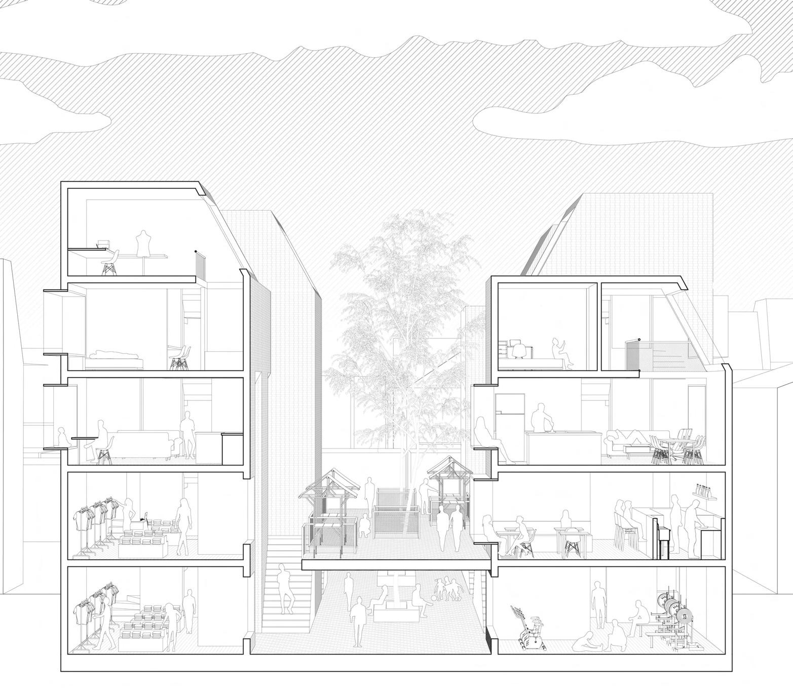
The ‘Experimental Collectivity’ studio sought to envision new modes of collective housing in Toronto in an effort to address the ‘missing middle,’ or the housing gap between suburban, single family dwellings and high-rise apartments. The Work Life Balance collective housing imagines a new community of housing and work space, creating flexible spaces for community events. Townhouses sit above storefronts and office spaces, with large, open plans allowing community events. A pedestrian street between the townhouses creates a large public gathering space, where market events occur. The chamfered roofs of the townhouses create skylights with double height spaces, providing airy, light, living spaces. Alternating window placement provides privacy in a dense living arrangement.
14
Townhouse ground +1, with kitchen and double height living room
ground +2, with bedroom, bathroom, laundry, and balcony
ground +3, with studio space
Ground store space, in typical daily configuration
Ground store space, transformed into runway for show
These floor plans show the flexibility of the units. Jennifer is an aspiring fashion designer and the owner of a vintage clothing store. During regular use, her storefront on the public lane acts as a store for her clothing finds,
as well as her own designs created in her studio on the top floor of her apartment. Each season, she converts her shop into a runway to show off her newly launched line of clothes.
15
Townhouse
Townhouse
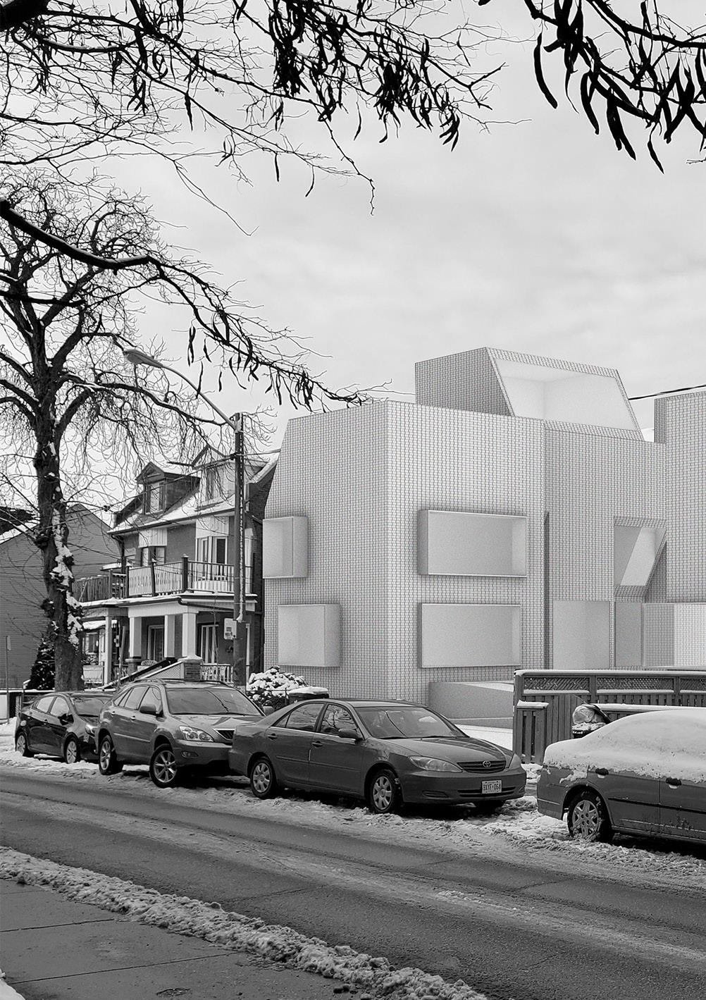
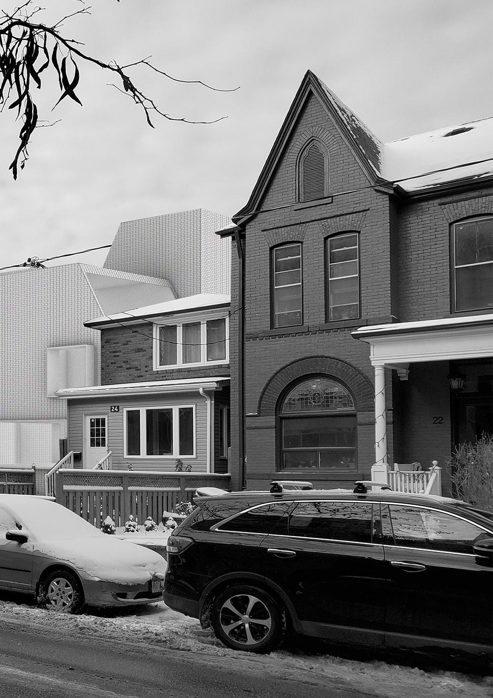
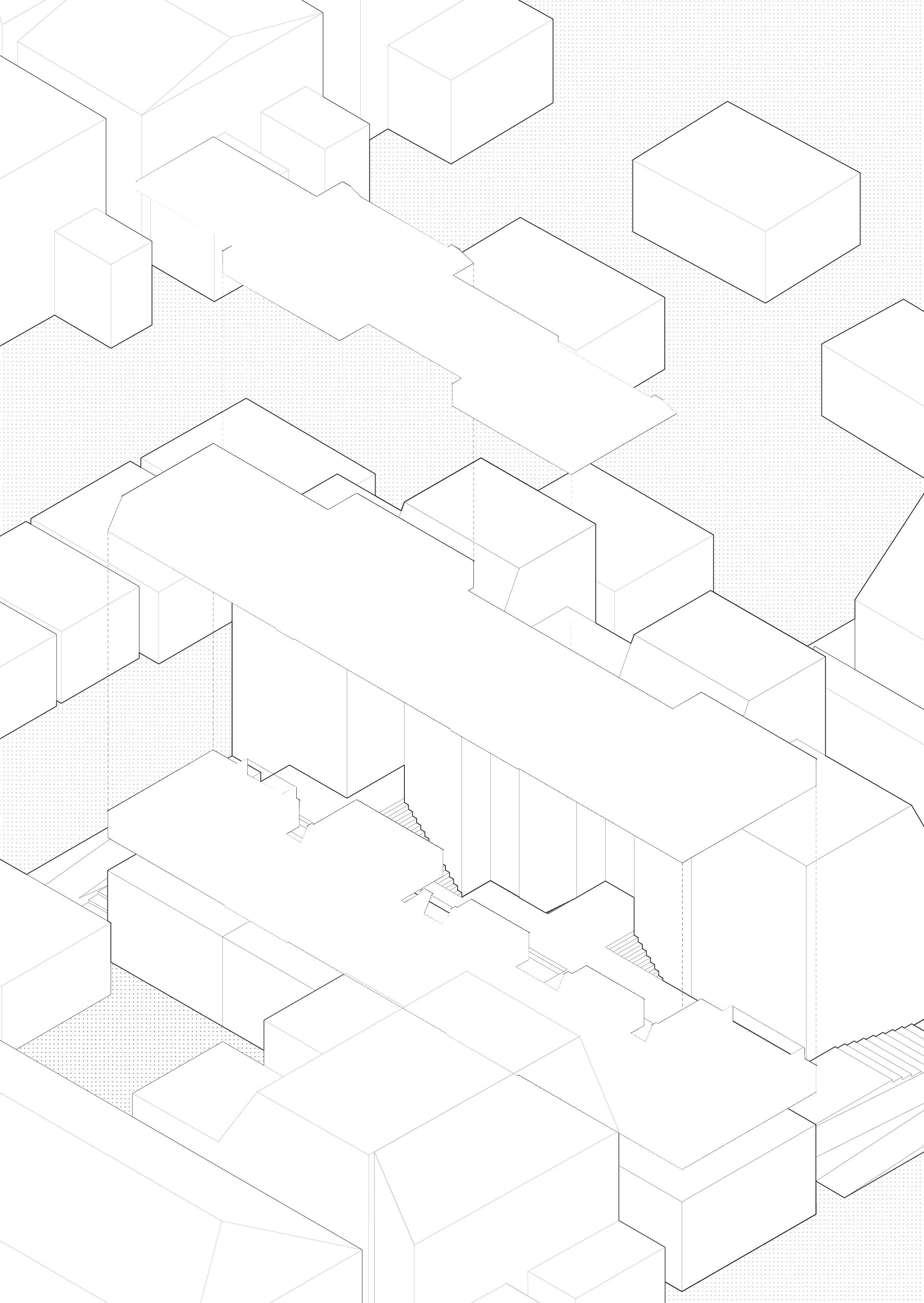
The units of the Work Life Balance housing collective consist of two and three story apartments, accessed from the ground floor retail space below. Each unit is lit by alternating windows and skylights, providing light and privacy.
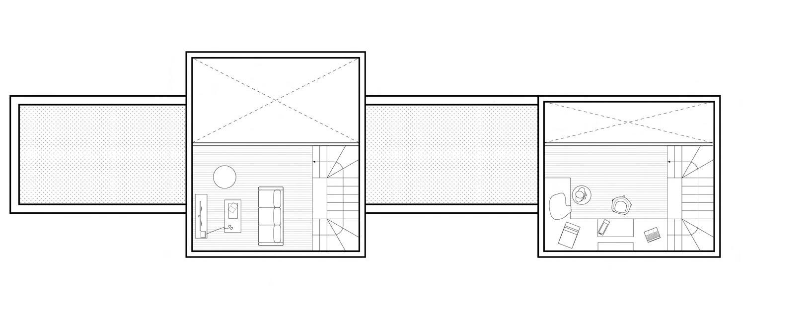
Ground +3
The top floor of the three story apartments are faced by the angled skylights, creating brightly lit lounges and workshops.
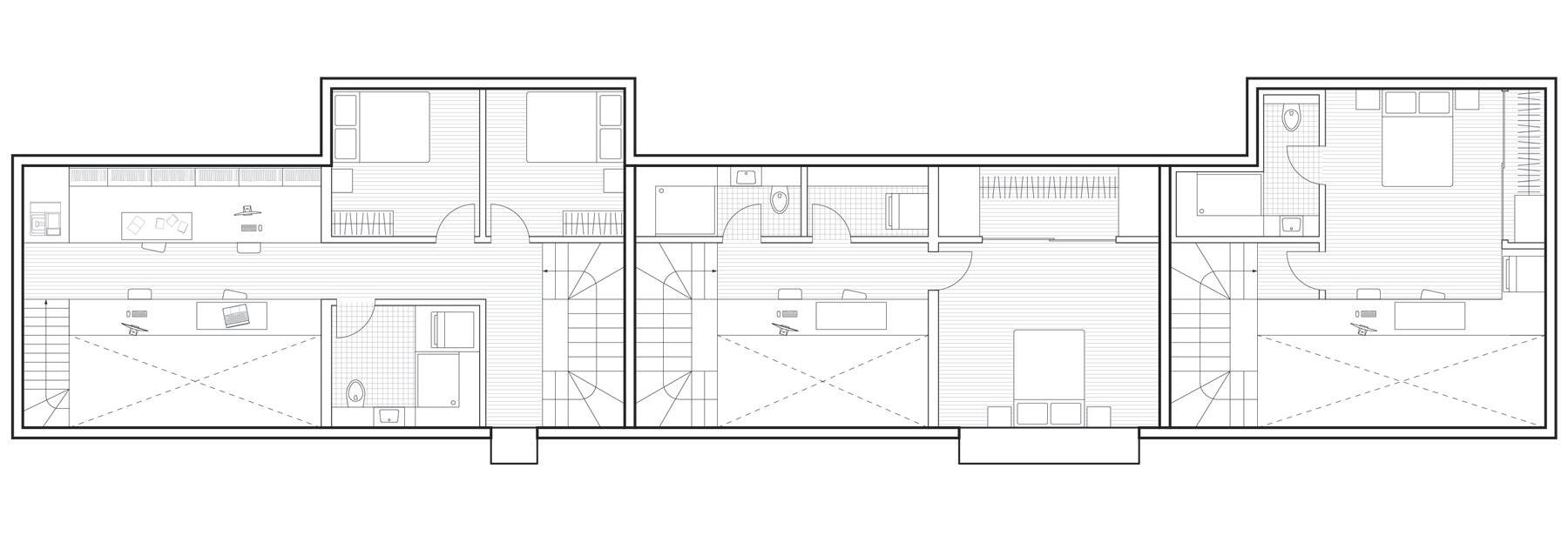
Ground +2
Work desks sit above the spaces created by the double height ceiling, overlooking the activity below and providing a connection to the lower area. Corridors are exploited to increase the amount of usable space.
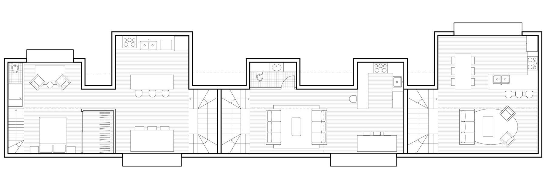
Ground +1
The first floor of the housing units contains spacious kitchens, living rooms, and bed rooms for small apartments. Angled windows on the floors above create well-lit, double height spaces.
19
Sudbury 2050
Re-imagining the post-industrial landscape in Northern Ontario
Site: Sudbury, Ontario large [medium] design office
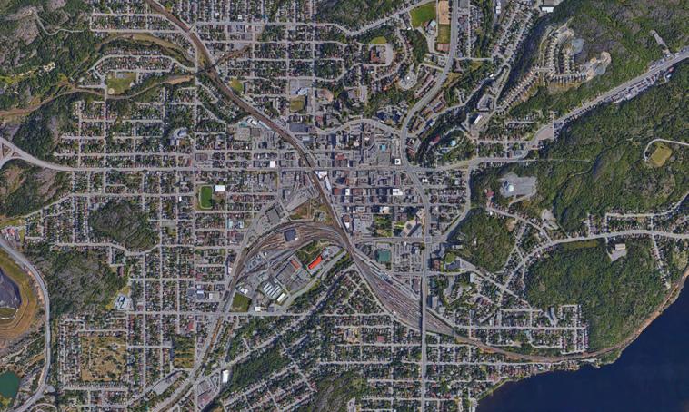
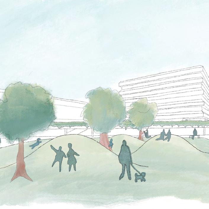
The Sudbury 2050 competition challenged participants to envision the redevelopment strategy of the urban core of Sudbury, a town in Northern Ontario, in the year 2050. A historic mining town in the midst of its transition away from heavy industry, the aging centre no longer adequately serves the town’s population.
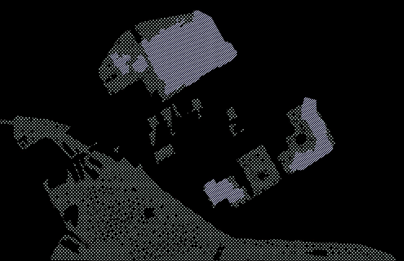
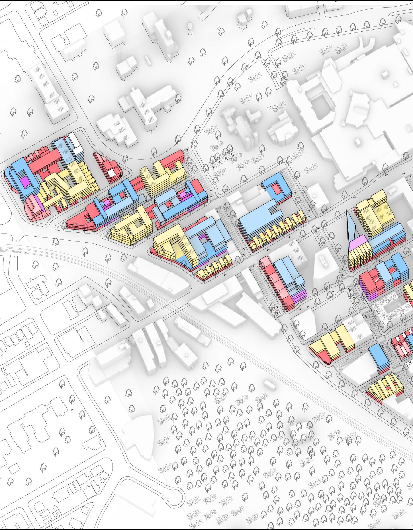
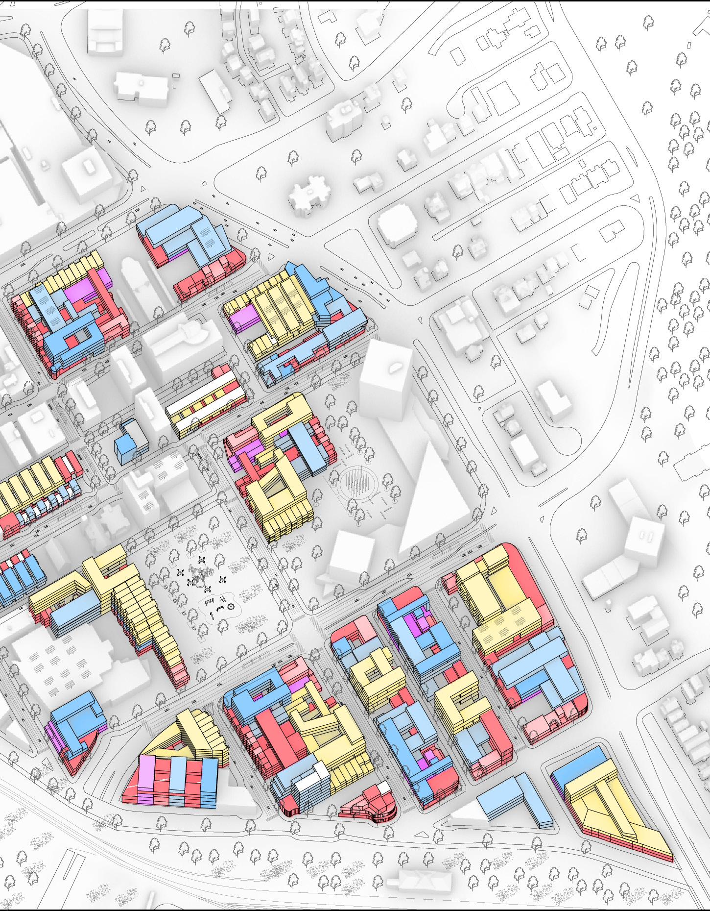
Our team began with a survey of the town’s current zoning plans, demographics, and current land use policies, compiling data in GIS to create a series of mappings. These mappings revealed the current program segregation, lack of adequate housing and program diversity within the downtown core, as well as the over-representation of parking space within the city centre. Our research also identified several key heritage and social value sites within and adjacent to the downtown core.
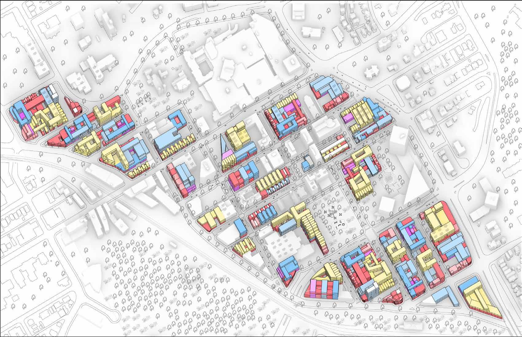
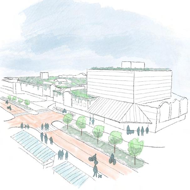
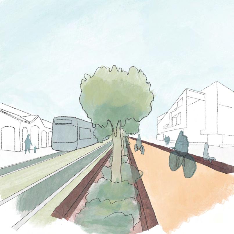
Our policy aims focused on creating an intensity to the city centre necessary for its rejuvination. Our proposal envisioned the city as a fine grain of program and a diverse set of users. Interwoven programmatic zones create opportunities for spontaneity and diversity within Sudbury’s city centre. Our surveys identified existing sites of historic and public interest, redeveloping them to create community hubs. These elements were connected with enhanced pedestrian and cycle infrastructure. Larger industrial elements, notably the current railway and railyard located adjacent to the city centre, were repurposed into large public parks and cycle highways, connecting planned future event centres and public institutions to Subury’s surrounding suburbs and natural reserves.
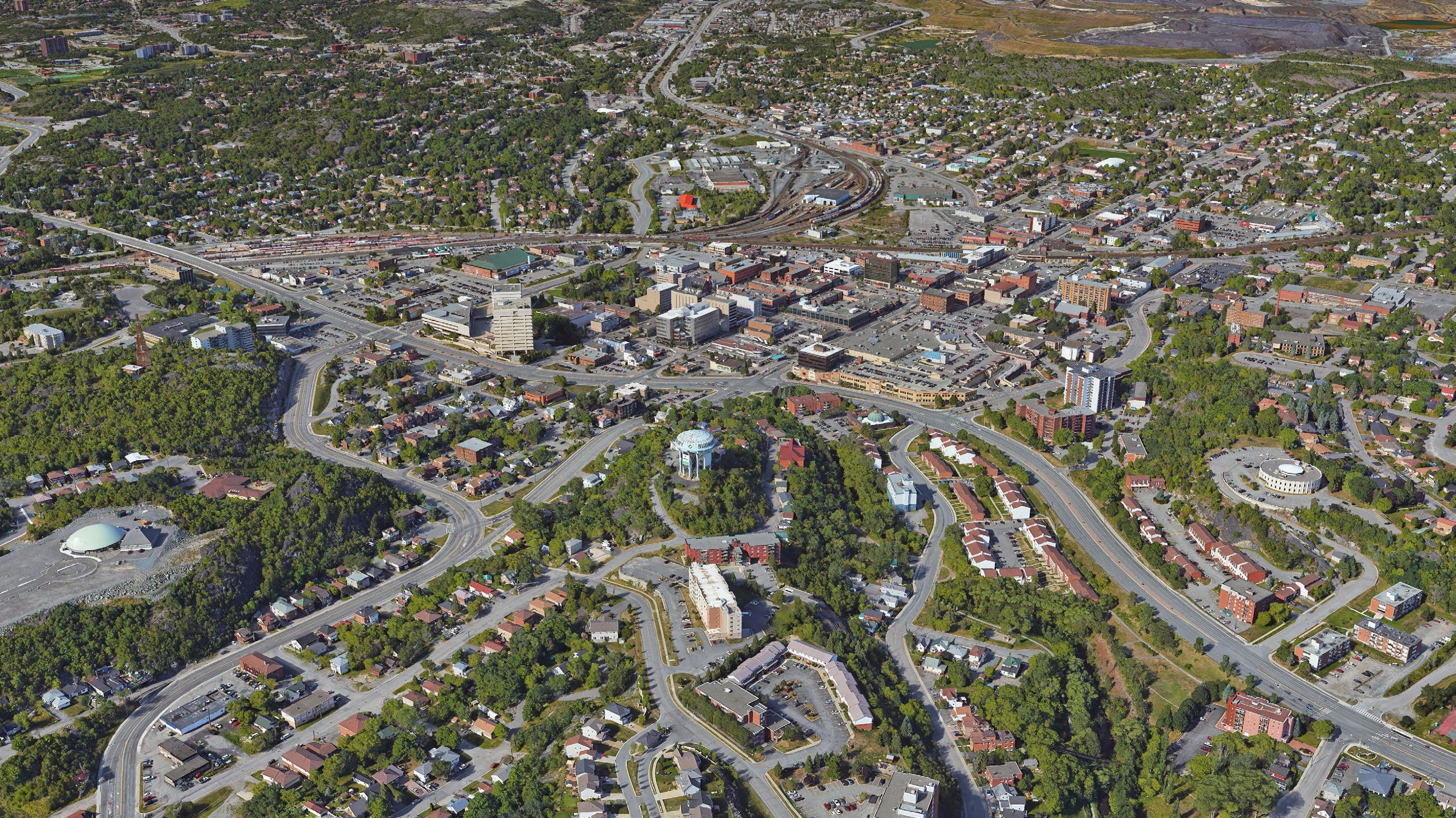 Sudbury Community Arena
Memorial Park
Tom Davies Square
Sudbury’s Water Tower
City Centre
Conseil scolaire catholique Nouvelon
20
All Nations Church
Grotto of Our Lady of Lourdes
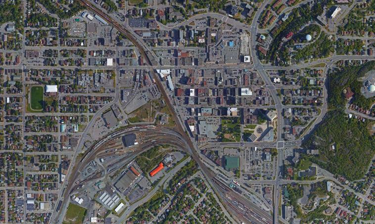
Parking lots on site 50m 250m Current Percent of total Proposed Proposed percent Population data CurrentPercent of total Proposed number Proposed by per ha Population proposals for downtown site Proposed number Proposed by per haInputs Step 1: Propose population for downtown site based on current population data. (F1-J10) Population (Greater Sudbury) 160765 Residents in downtown (incl. surrounding residential areas) 600 600599.815383Residents in downtown site 20003298.7523 Outputs Step 2: Enter proposals into Population proposals (purple) (K1-M10) Residents in downtown core 6000.37% Residential area 464613 464613464613Site area 464613464613 Step 3: Calculate required figure based on proposed density in Figure compared to density chart (red) (K12-M16) Shoppers in downtown core (daily) 150009.33% Residential units 368.0981595 368.0981595368.0981595Residential units 1226.9938652023.774417 Age 1-19 3563022.16% Units per hectare (downtown core total area) 7.92 7.927.92Units per hectare 26.41 43.56 20-29 105456.56% Residents per unit 1.63 1.631.63Residents per unit 1.63 [1] 1.63 30-44 3017018.77% Population per hectare 12.91 12.9112.91Population per hectare 43.05 71.00 45-59 3849523.94% Jobs 6000 6000 5993.5077 Jobs 6000 5993.5077 60-74 2434515.14% Jobs per hectare 129.1397357 129.1397357 129 Jobs per hectare 129.1397357 129 75+ 118507.37% Jobs and residents per hectare 142.05 142.05141.91Jobs and residents per hectare 172.19200.00 Land use (downtown core) Current Percent of total Proposed Proposed percent Land use (downtown core) ProposedPercent of total Figure compared to density Current Proposed Commercial/Retail 7533616.21%69691.9515.00%Commercial/Retail 47390.52625.50% Percentages are in relation to each other Jobs and residents per hectare 142.05200.00 [2] Industrial/Employment247365.32% 0 Industrial/Employment 27876.7815.00%= 100.00%Figure per hectare (sqm) 3287.230448 4000 Residential 67501.45% 0 Residential 65975.04635.50% of figureFigure per density (sqm) [3] 23.14075758 20 Community building 106862.30% 0 Community building 7433.8084.00% Percent total of combined Industrial/E mployment, com/ret, arts Total figure required for total density 152729185845.2 Land use figures only include ground floor area. From surveying downtown through streetview it seemed like average building height was about 4 stories. Entertainment/Restaurant122492.64% 0 Entertainment/Restaurant 18584.5210.00%= 50.50% Institutional 229724.94% 0 Institutional 18584.5210.00% Figure percentages Parking (as a percent of ground) 8773728.13% 0 Parking 27876.7810.00% Percent residential 4.42%35.50% Parking (as a percent of total area) 8773718.88% Parking (total area) 27876.786.00% Percent commercial, Industrial/Employment, retail, Entertainment/Restaurant 73.54%50.50% Open space (sidewalk and parks in core) 7142515.37% 0 Open space (sidewalk and parks in core) 7142515.37% Percent institutional and Community building 22.04%14.00% Street 7664316.50% 0 Street 7664316.50% Figure 15272932.87%185845.240.00%Figure 185845.240.00% Ground 31188467.13% 0 Ground 278767.860.00% Total (core) 464613100.00% Total (core) 464613100.00% Land use (total site) Current Percent of total Proposed Proposed percent Program breakdown Percent Units Commercial/Retail 11154012.64%132387.1515.00%Commercial/Retail 16.21% 49% Owned housing 66.10% 1338 Industrial/Employment247362.80% 0 Industrial/Employment 5.32% 16% Required affordable 37.00% 495 Residential 67500.76% 0 Residential 1.45% 4% Community building 106861.21% 0 Community building 2.30% 7% Rental 33.90% 686 Entertainment/Restaurant122491.39% 0 Entertainment/Restaurant 2.64% 8% Required affordable 49.00% 336 Institutional 275223.12% 0 Institutional 4.94% 15% Figure 19348321.92%353032.440.00% 100% Current Required Parking 14775216.74% 0 Apartment (High and medium density 1.56%40.00% Street 766438.68% 0 Detached (Low density) 98.44%60.00% Rail lands 14934316.92% 0 Ground 68909878.08% 0 Total (sqm) 882581100.00% Transportation Current Percent of total Proposed Proposed percent Block area total FAR Parking spaces 3000 387536 Block size 4669 Insert block size Daily transit passengers15000 Percent of total 1.20% Kingsway event centre proposed capacity 6500 Existing 528 Insert existing building footprint total Floors 2 Insert number of floors Space of standard parking space (sqm) 14.56 Gross floor area 1056 Total parking space required 43680 FAR 0.23 Required FAR 1.92 Added FAR 0 Bricks by program Commercial/Retail 2014.5525.50% 7 Industrial/Employment 1185.0315.00% 4 Residential 2804.5735.50% 10 Community Building 316.014.00% 1 Entertainment/Restaurant 790.0210.00% 3 Institutional 790.0210.00% 3 Land use figures only include ground floor area. From surveying downtown through streetview it seemed like average building height was about 4 stories. Total required for block excluding existing (kept) buildings 7900.187181 Bricks required (4x4) 27 Open space 291.8125.00% Total site FAR (Downtown Core) 1.58 Required 1.918223855 Greater Sudbury Public Library Church of Christ the King McEwen Architecture School Big Box Supermarket Hardware Store Steelworkers Union Hall Sudbury Community Arena VIA Rail Sudbury Place des Artes (in progress) ParkSide Older Adult Centre Transit Hub City Centre Mall St Mary’s Ukrainian Catholic Church Tom Davies Square Post Office Sudbury Theatre Centre Sudbury Fire Station Northubury Hotel St Philomena Mission Office Residential Transit Civic Arts and Entertainment Institutional Commercial/Retail Building type by use Public Private Zoning Layers Institutional Low Density Residential One Low Density Residential Two Medium Density Residential Mixed Light Industrial/Service Commercial Office Commercial Open Space - Private Open Space - Conservation Business Industrial Downtown Commercial General Commercial Park High Density Residential 50m 250m 100m 500m 3 minutes bike 8 minutes bike 15 minutes walk 8 minutes walk 21 Building program map Current zoning designations
centre radius map
data Land use, roads, and parking mapping
City
Demographic and land use
r a n t , s a fer s treets t hrough pedestrian a nd cycle
itaer n g biv
t he downtowncoreto community c e n tres, suburbs, andnational park s Rev italising industriallandto create cycle a n d light rail infrastructureconnecti n g th e

C
priorityzones

Heritage sites selected for restoration Urban green space

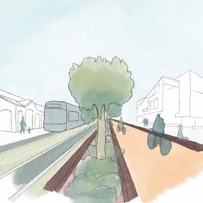
Pedestrian and cycle priority zones

R ep
to
green spaceand social val ue
u b s
urp osing heritagesites
create u r b an
h
Bicycle highway
Light rail
The Lantern Natatorium
Revitalising industrial land with community focused architecture
Site: The Golden Mile, Scarborough, Ontario Team members: Yvonne Fu, Chris Lam
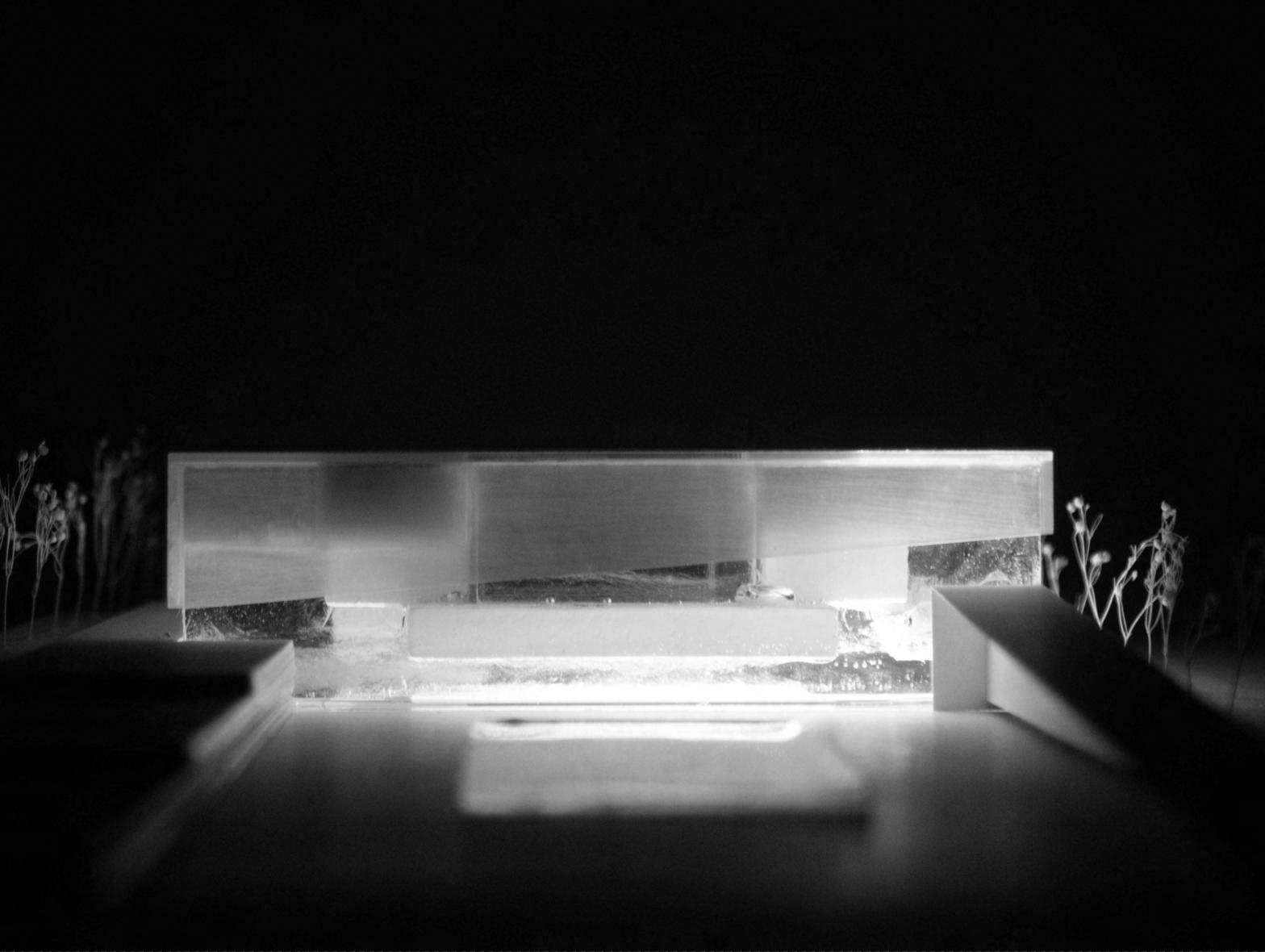
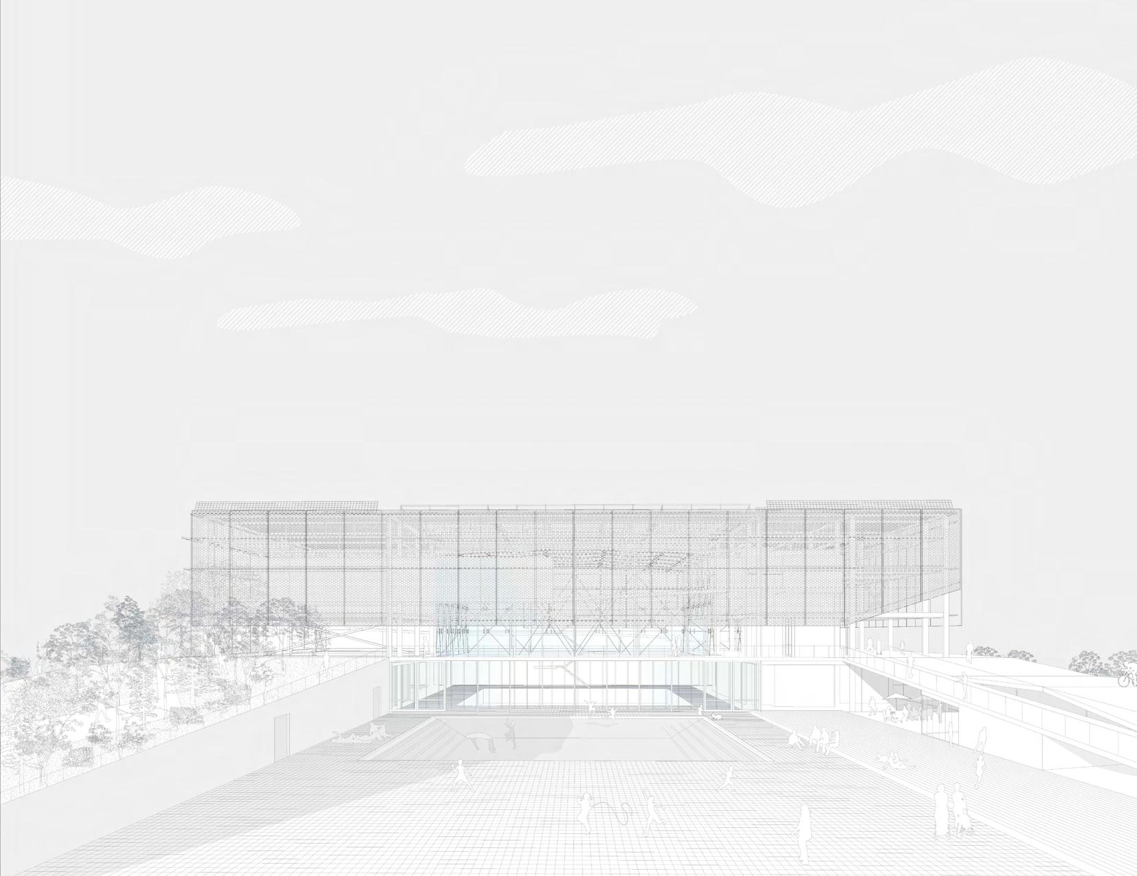
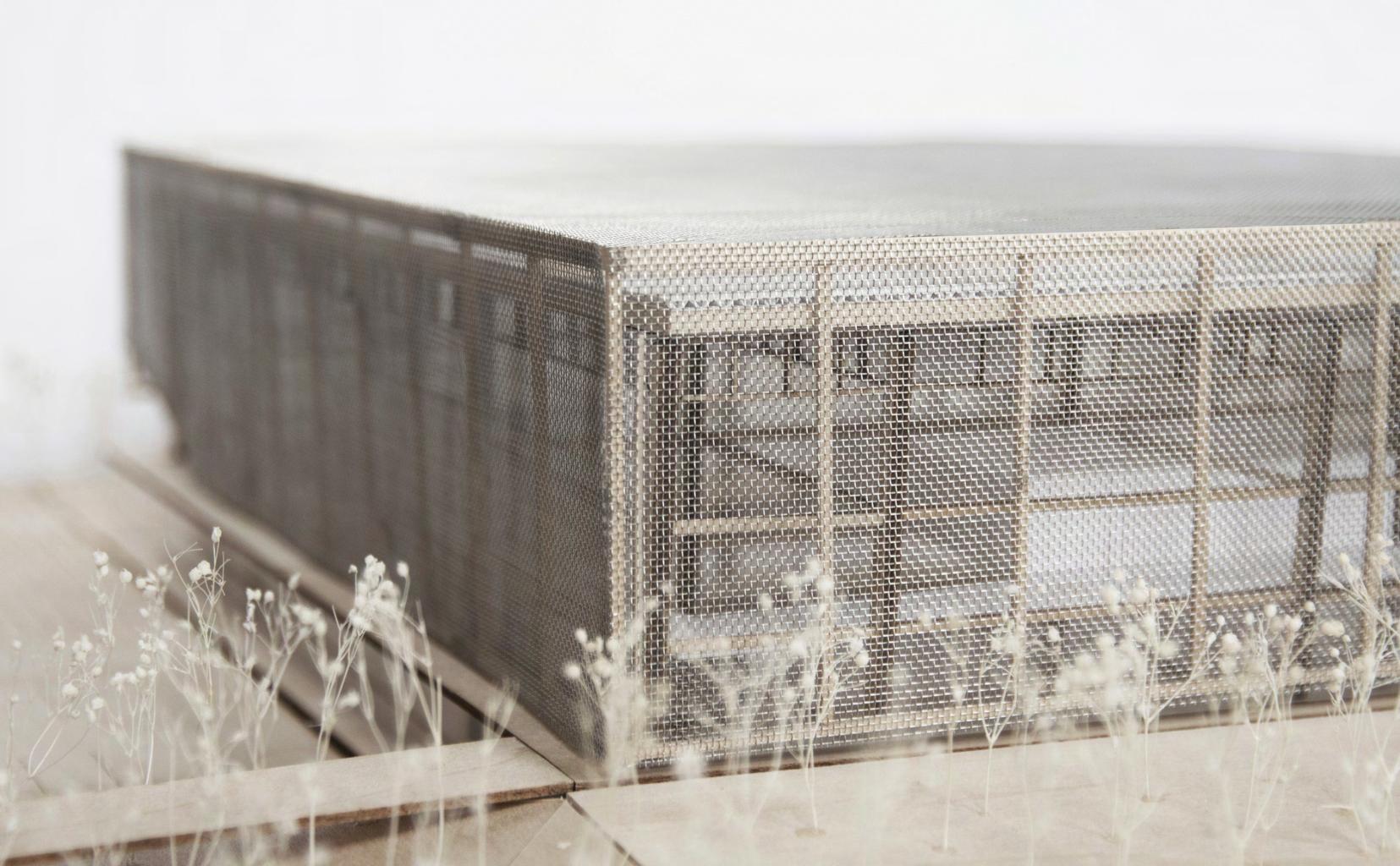
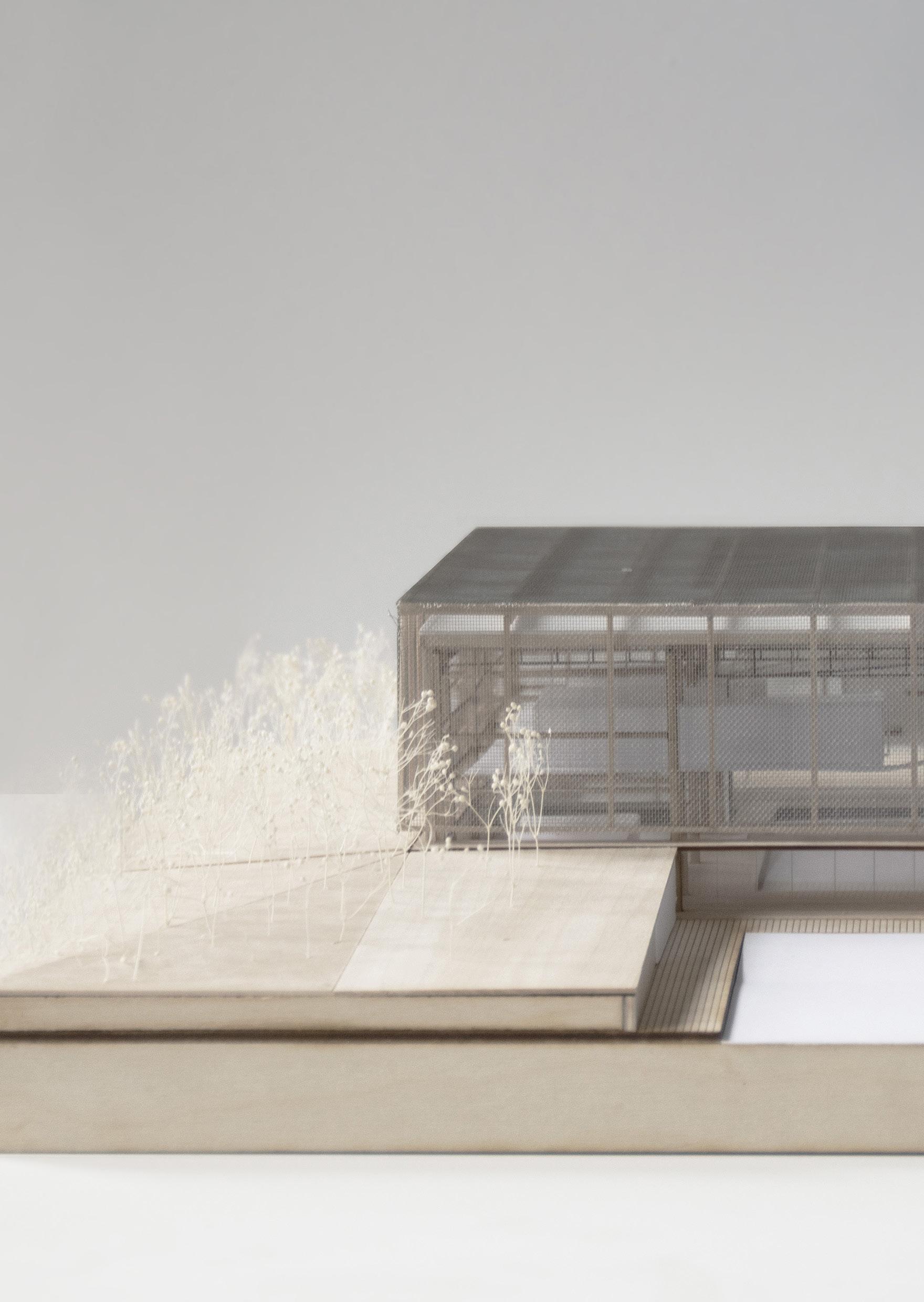
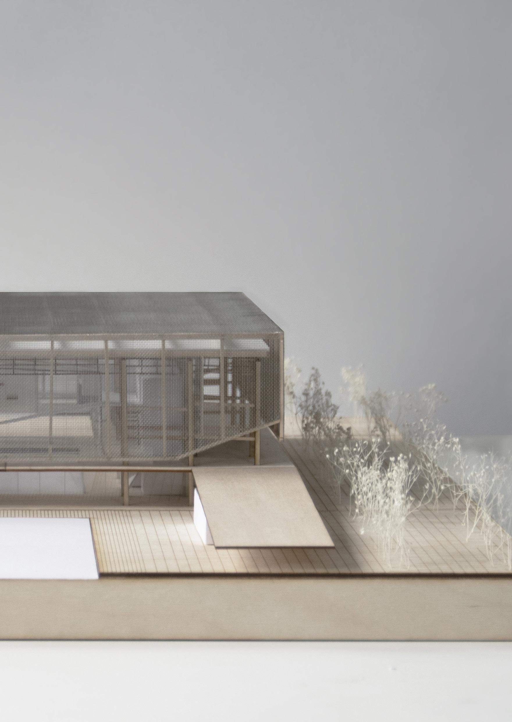
The Lantern Natatorium creates a centrepiece for the Golden Mile Secondary Plan, an urban renewal strategy put forward by the city of Toronto to revitalise the Golden Mile, a former industrial site in Scarborough, Ontario. The natatorium’s soft glow, created by its curtain wall system shrouded by an expanded metal veil, acts as a beacon on the edge of the hydro-corridor behind it. The Lantern is subtly raised to be visible from all sides, as well as visually connecting it to the hydro-corridor. A bike path wraps up and around the edge of the natatorium, extending the access between the streetfront and the green space behind. The veil lifts at the corner to allow access to the natatorium, as well as to the covered outer space.
The Lantern utilises passive control methods to promote an environmentally responsible architecture. The south facing siting of the outdoor pool provides heat and light. Operable windows provide passive ventilation, and only necessary program is regulated, leaving the pavilion-like circulatory area passively controlled.
24
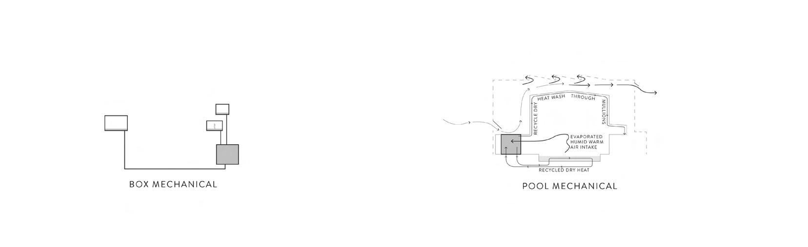
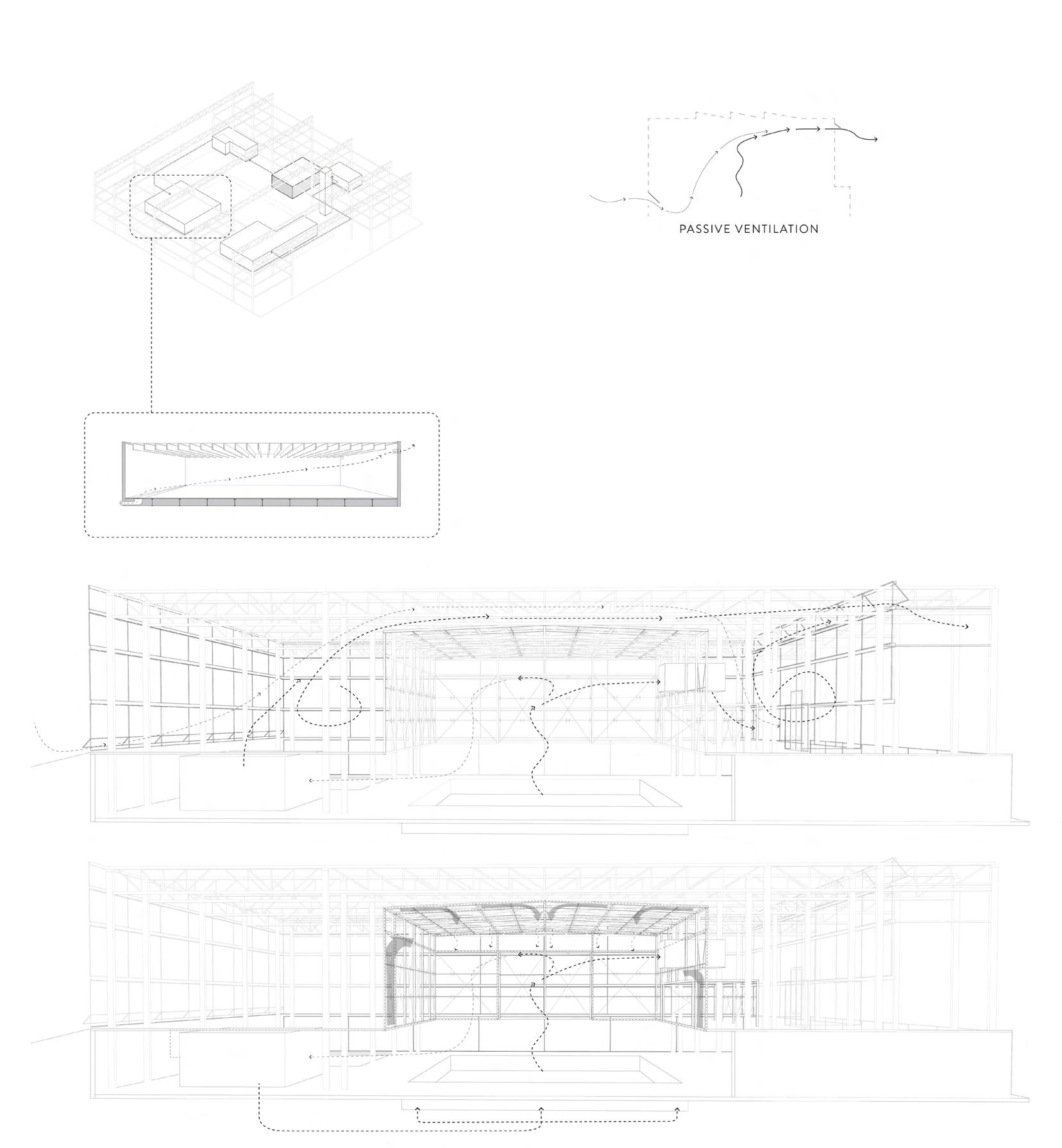
The Lantern Natatorium connects essential program to mechanical services, while relying on passive ventilation systems to mitigate systems load and reduce the building’s carbon footprint. Operable windows and ventilated rooms cool program spaces, including offices, gyms, and the cafe, during the summer, while warm, humid air from the insulated pool space is recycled to provide dry heat to the spaces during the winter and colder days.
26
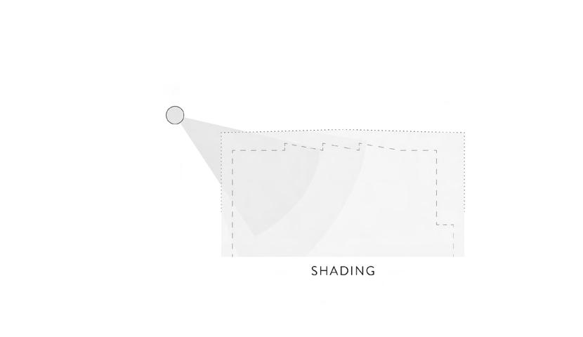
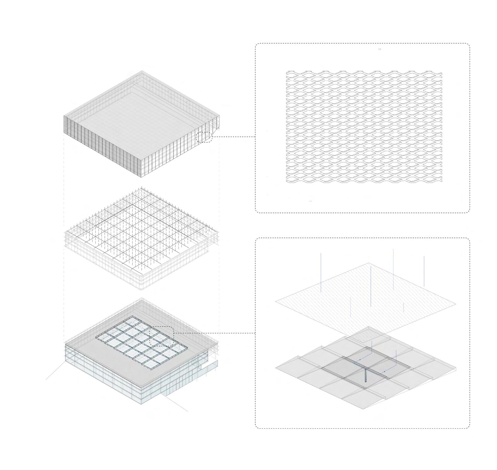
Shading systems shield the glass facade, reducing heat gain while maintaining natural light throughout the building. Through material experimentation, including glass block, illuminated concrete panels with fibreglass rods, and parametric wood slats, perforated metal was chosen for its weight and porousness. The glass roof of
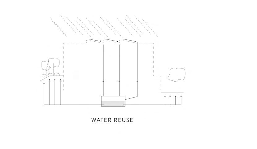
the natatorium acts as both a skylight and rain catchment system. The perforated facade allows water to drain through to the roof, where a system of channels directs water from the roof to rain tanks, where water is recycled for the pool and adjacent landscape.
27
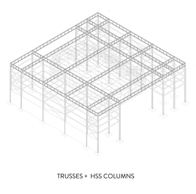
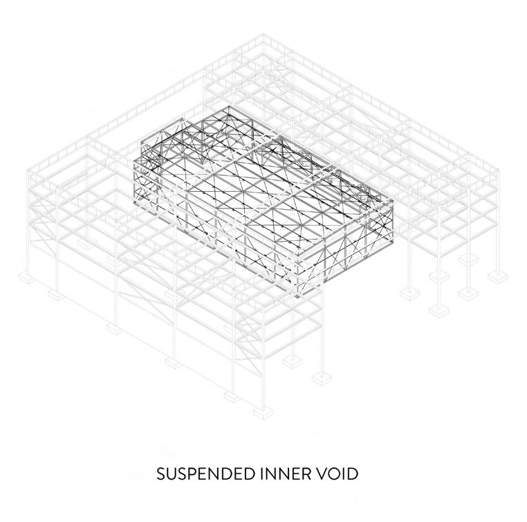
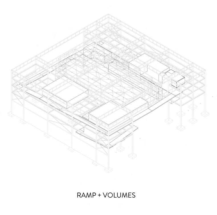
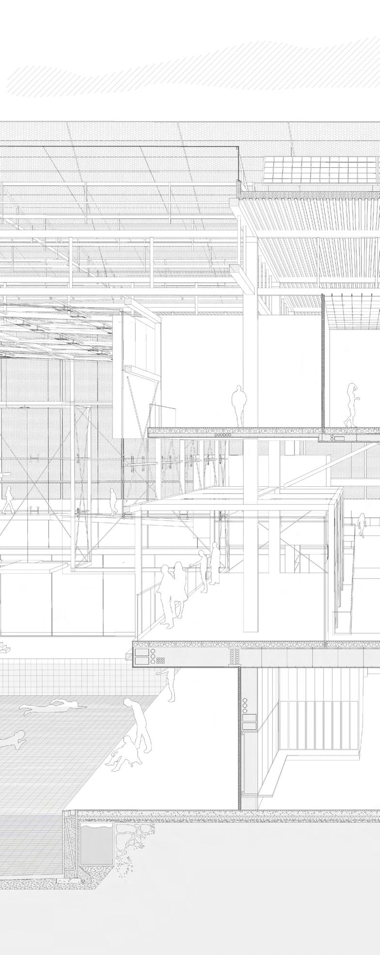
The structural steel shed system with vierandeel trusses and HSS columns supports the ‘floating box’ program elements, ramp, floor plates, and inner atrium. By suspending the atrium, the system creates an enclosed humid zone, allowing light to enter the pool area while preventing the transfer of heat and humidity, as well as the creating the glowing heart of the natatorium.
28
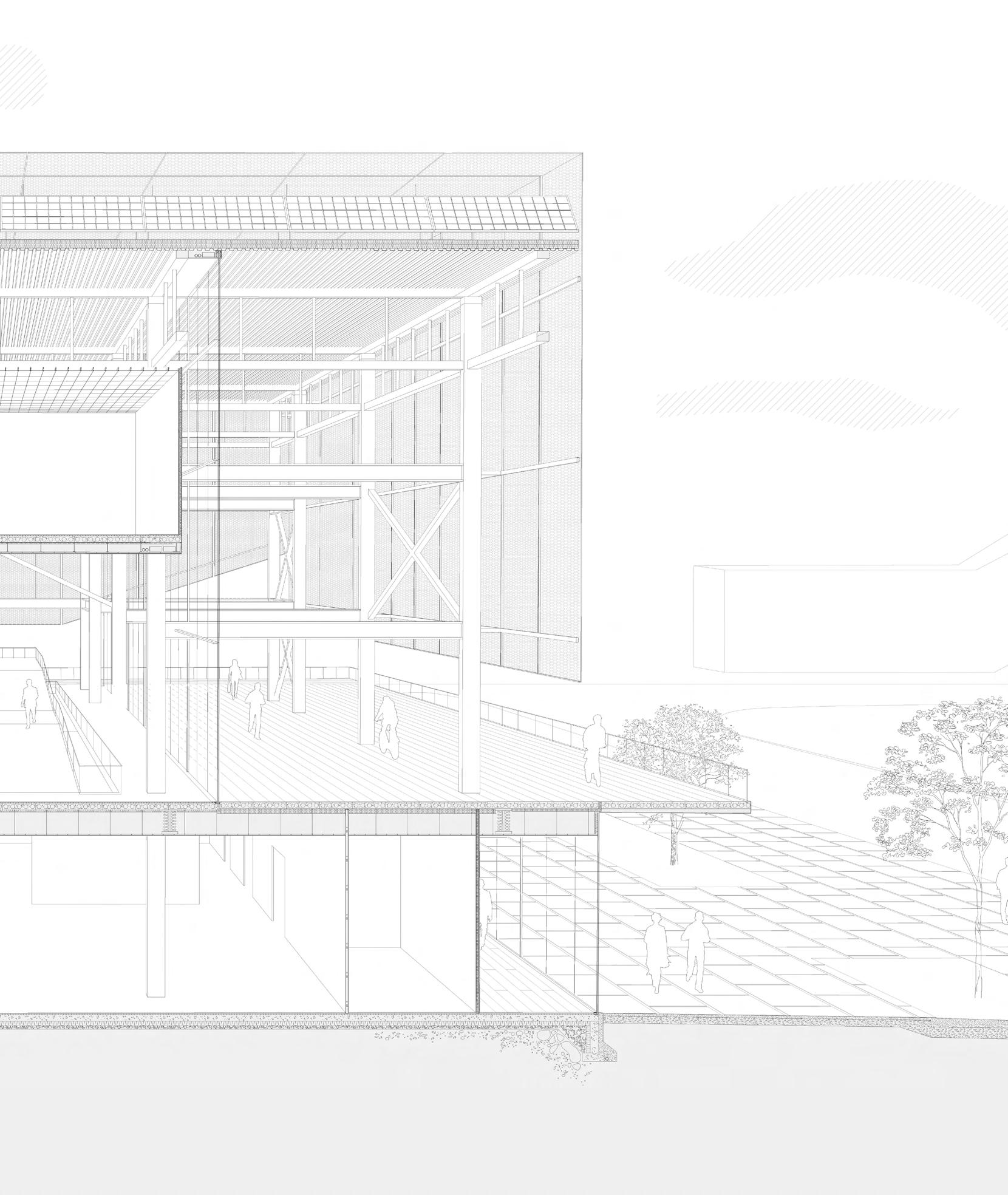
Suspended volumes are arranged around the central atrium, which provides light and enclosure to the pool area below. The volumes surrounding the atrium overlook the pool, connecting all programs to the central focus. These programmatic volumes, including gyms, offices, and cafe, are accessed by a ramp which wraps its way around the atrium, connecting the program spaces while
providing views of both the pool area and the landscape beyond. The outer walkway ramps up to the second level, creating a separate entrance to the dry areas, as well as providing hout to the outer loggia area. This outer space, which hugs the exterior of the natatorium, provides a place to pause between the historic Golden Mile commercial area and the hydro-corridor to the North.
29
207: Cottage in the Shade
Site: Minden Hills, Ontario
Works Office of Brian O’Brian Architect
Status: Pre-construction
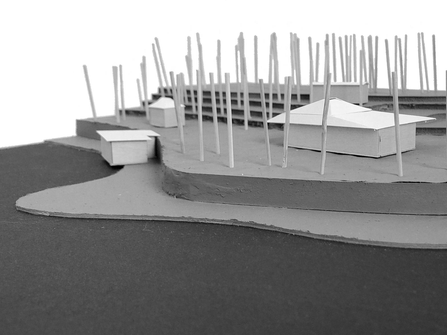
The Cottage in the Shade consists of a cottage and outbuildings on a lakefront property in Southern Ontario, commissioned to replace a 1960s cottage that no longer suits the needs of the family.
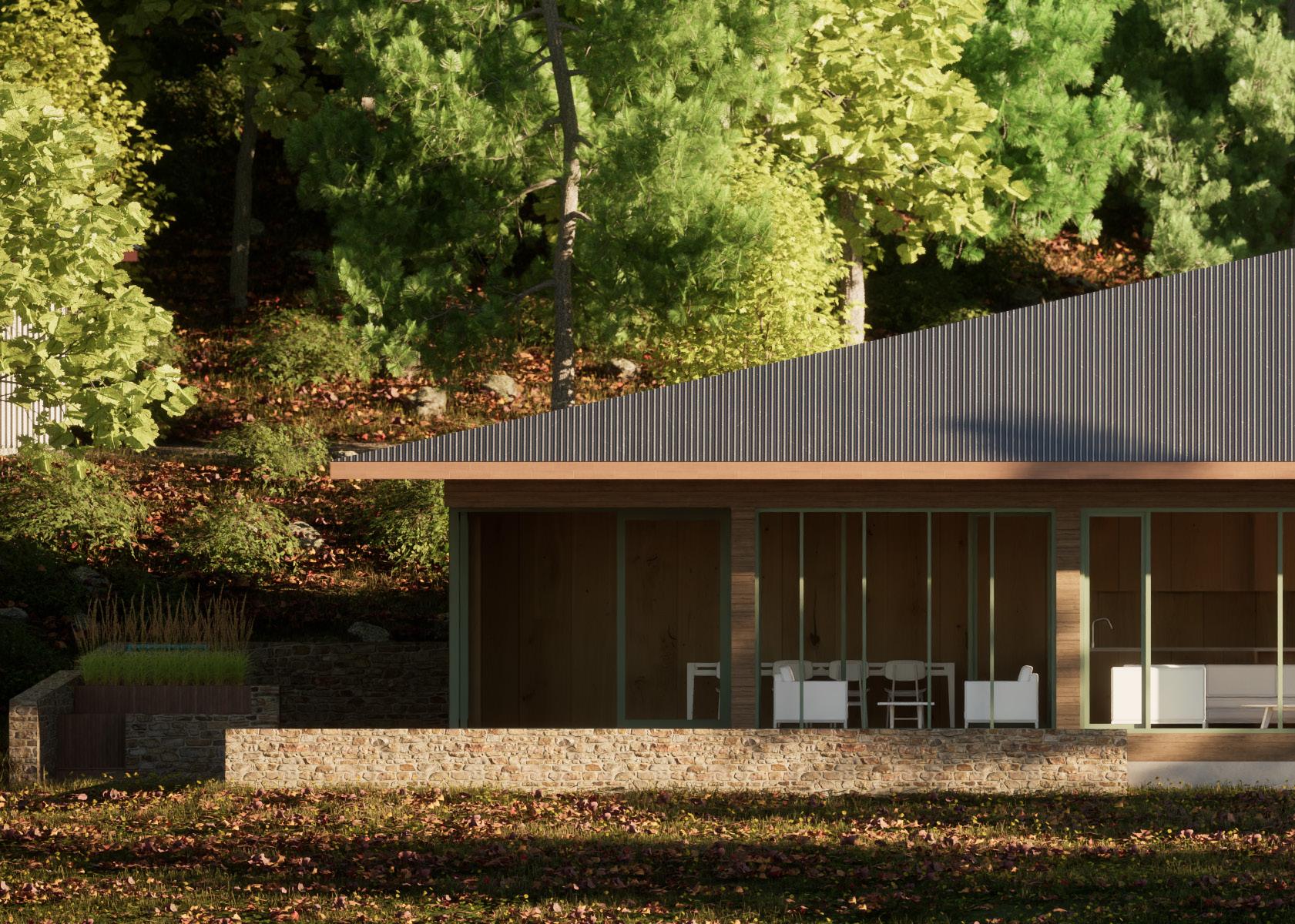
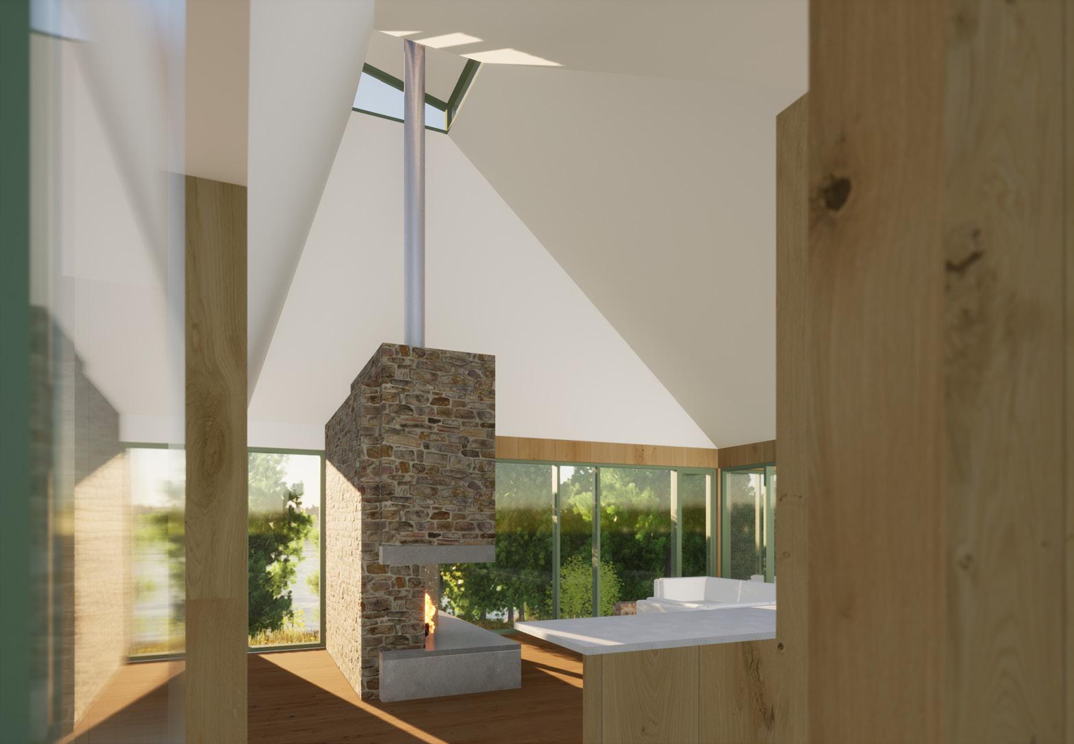
The building consists of a series of horizontal spaces beneath a singular bent roof. The central living spaces push into the roof to heighten the space, allowing for passive ventilation and light through a central skylight.
The cottage is oriented to frame views of its surroundings. The principal bedroom occupies the Southwest corner of the cottage, with clerestory windows along the south of the building to let in morning light. The kitchen, dining, and living spaces are situated to the Northwest, with views of the lake and boathouse. The secondary bedrooms are arrayed along the East, accessed by an axial corridor, and give the feeling of nestling into the Eastern slope.
32
33
Ground floor plan
1/16” = 1”
Roof plan
1/16” = 1”
Basement plan
1/16” = 1”
The plan of the Cottage in the Shade makes use of two main axes: a North-South axis dividing the lakeside program and the hill program, and a diagonal axis which directs users from the Southeastern property entrance, through the residence, and towards the Northwestern boathouse and lake.
The program is reflected in the ceiling above. Bedrooms, bathrooms, and other private spaces sit beneath the lowered areas. Moving into the public spaces through the corridors, the ceiling begins to lift. These corridors are separated by screen walls, yet retain their connection to the public space through the ceiling. The ceiling reaches its apex beneath the hearth.
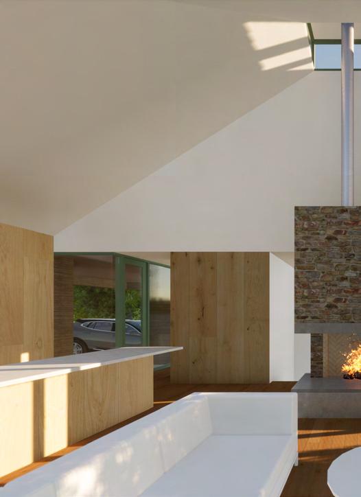
34
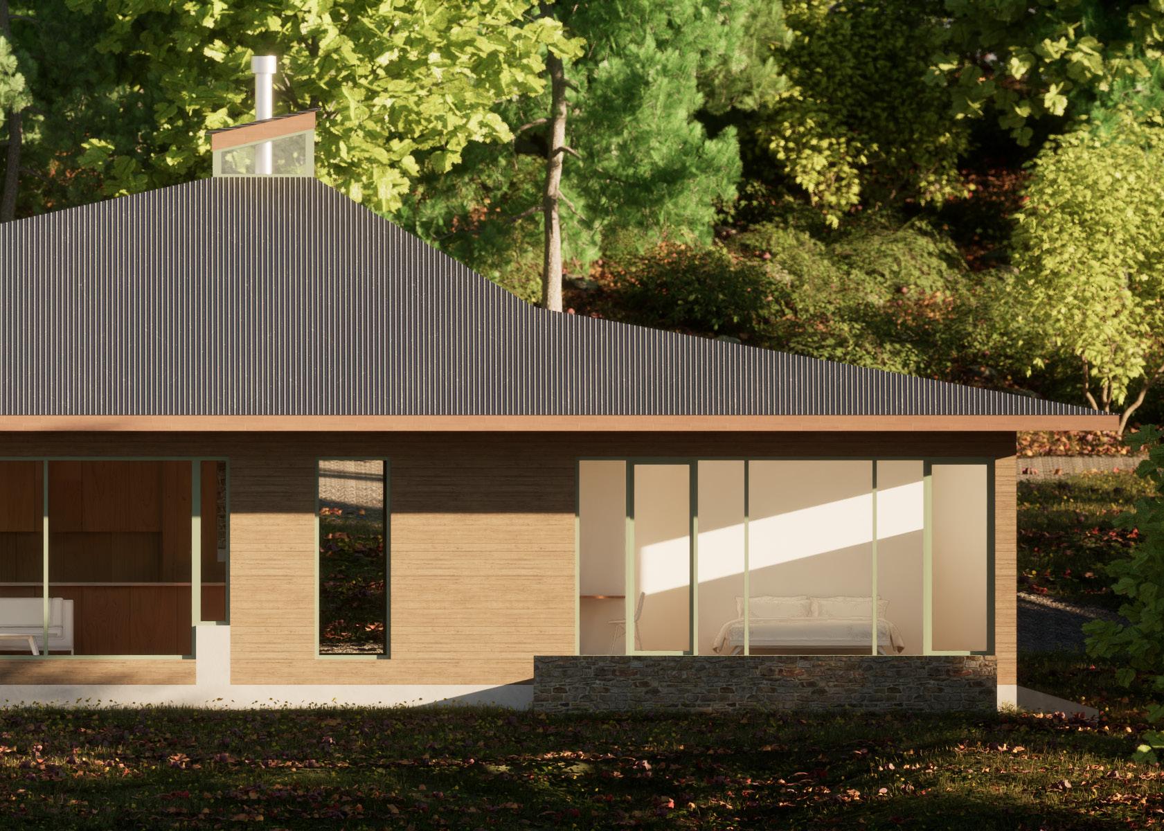
The structure is inteded to be clad in horizontal hemlock board, and capped with a unified corrugated steel roof. Dry-laid stone walls frame the exterior cedar decks and outdoor kitchen, referencing the stone retaining wall laid by the owner, as does the central hearth. Warm white oak floors, wall panels, and millwork tie the interior spaces together.
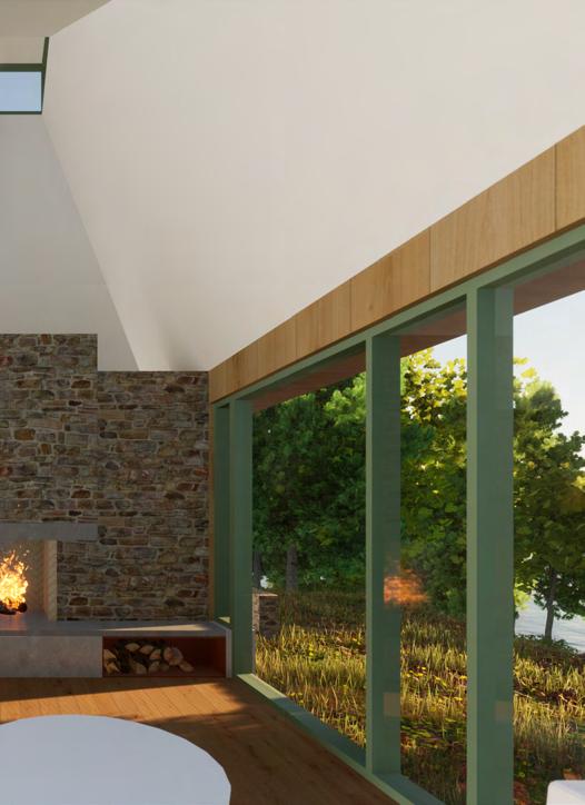
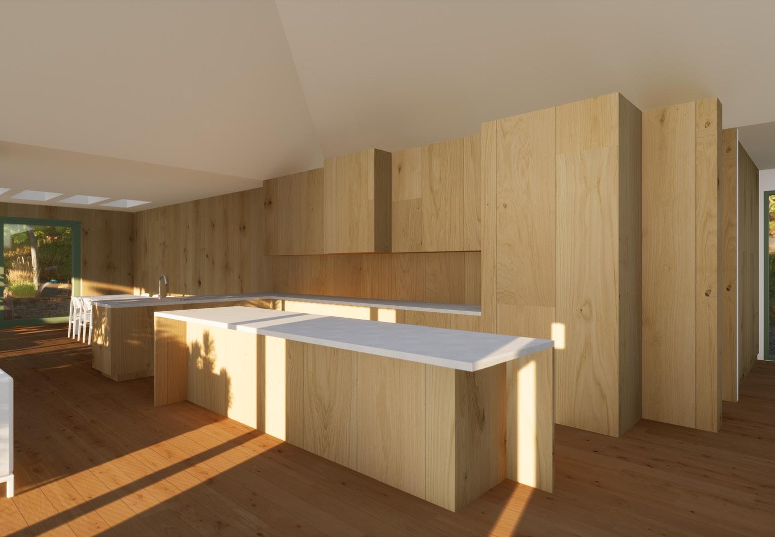
35
Top: West elevation
Bottom, from left to right: Views from entrance, living room, kitchen
194: Acropolis Grey
Site: Ravenna, Ontario
Works Office of Brian O’Brian Architect
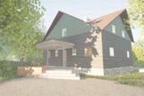
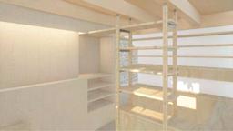
This 32’-0” by 32’-0” wood cabin was built by a shipwright. The current owners approached the firm to improve the interior layout of the cabin as well as to replace an existing Northwestfacing sunroom and the East front porch.
The existing interior space was divided into two halves, with the Eastern side consisting of a cramped mudroom entryway, powder room, enclosed office space, and kitchen. The Western half of the cabin included an open living room, central hearth, and a small dining area. The proposed interior plan reorganised the Eastern program into a more functional and open layout which made use of a series of distinct yet interconnected millwork pieces to intensify the depth of program.
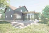
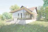
The sunroom is shifted to Southwest corner. Its butterfly roof lifts upwards, inspired by a ship’s prow, as well as allowing more light to enter from the Southwest. Glazing wraps the exterior of the sunroom, with operable windows set into framed glass panels to create airflow and reduce the cost from a full window system, and opens the sunroom onto the rural surroundings.
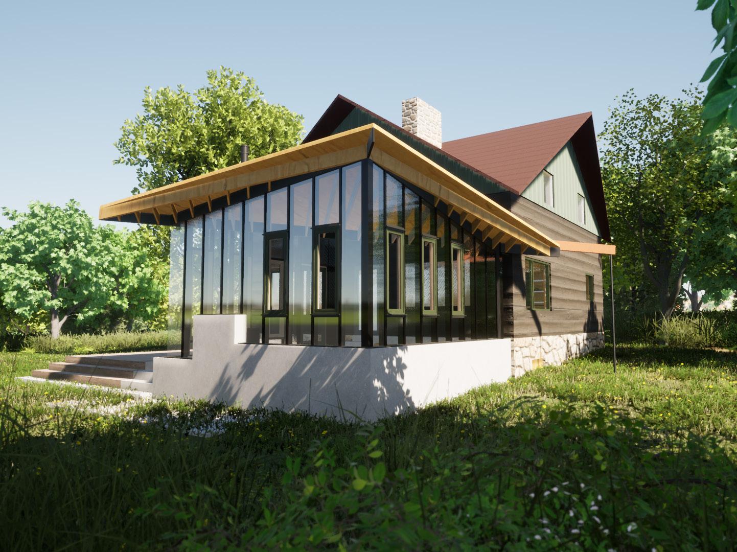
36
Bottom: Sunroom and porch plans
37 1 SUNROOM AND REAR DECK PLAN 3/8"=1'-0" 101 REAR DECK 102 DN 2x12 CLEAR CEDAR TREAD 2x12 CLEAR CEDAR TREAD 2x CLEAR CEDAR EDGE BOARD 16'-8 3/4" 1'-6 1/2" 2x CLEAR CEDAR EDGE BOARD DN 5-1/4" x 5-1/2" CLEAR DECKING ON PT FRAMING 16'-8 3/4" F.O. FDN TO EDGE OF DECK (EQ 'A') 4'-1" CONC STAIR 12'-7 3/4" CONC LANDING TO EDGE OF DECK OUTSIDE EDGE OF ROOF ABOVE PERIMETER BEAM ABOVE A202 3 SUNROOM AND REAR DECK RENDERS A 4 FRONT ENTRANCE RENDERS A ADDITION EXISTING 17'-1" CONC PAD 1/4" F.O. POST TO F.O. CLADDING 04 03 05 05 02 05 02 05 02 04 1 04 02 05 02 05 06 06 07 08 01 07 01 07 01 07 03 01 VALLEY(RIDGE)BEAMABOVE STEEL 1-1/2" 5-1/2" 3/8" THK FABRICATED TUBE SECTION CONC FLOOR, GROUND AND POLISHED JOTUL F602 POURED CONC BENCH W/ WOOD STORAGE BELOW POURED CONC STEP 1 20'-3 1/4" F.O. EXG CABIN TO F.O. FOUNDATION 20'-0" F.O. EXG CABIN TO F.O. CLADDING 3 1/4" F.O. POST TO F.O. CLADDING 1'-11 1/2" 2'-0" 2'-0" 2'-0" 2'-0" 2'-0" 2'-0" 2'-0" 1'-11 1/2" 1/4" F.O. POST TO F.O. CLADDING PER FDN PLAN SCUPPERABOVE GRAVEL DRY 1/4" F.O. POST TO F.O. CLADDING 1'-11 1/2" 2'-0" 2'-0" 2'-0" 2'-0" 2'-0" 2'-0" 2'-0" 1'-11 1/2" 18'-5 1/2" F.O. CLADDING TO F.O. CLADDING 19'-0" F.O. FDN TO F.O. FDN 2 FRONT ENTRANCE FLOOR PLAN 3/8"=1'-0" ℄ FRONT DOOR 100 5-1/4" 5-1/2" CLEAR FLUSH EDGE OF ROOF ABOVE 2xCLEARCEDAREDGEBOARD 2x12CLEARCEDARTREAD2x12CLEARCEDARTREAD 10'-0" DNR 3 3/16" +/- THK WEATHERING STEEL WITH 1-1/2" FOLDED TOP EDGE. LINE WITH 1" RIGID XPS INSULATION AND FILTER FABRIC. FILL WITH TRIPLE MIX. 14'-0" 7'-083/256"PLANTERBOX 7'-0"PLANTERBOX 45.0000° EXG WELLHEAD WITHIN NEW CONCEAL FROM VIEW POST CEDAR POST EDGE OF ROOF ABOVE 5'-0" 5'-0" 10'-0" 3B A202 A202 WINDOW AND GLAZING SCHEDULE TAG QTY WIDTH TYPE HEIGHT NOTES 22-1/2" R.O. LH CASEMENT WITH FIXED GLASS ABOVE/BELOW CASEMENT: 81" (82" R.O.) 22-1/2" R.O. LH CASEMENT WITH FIXED GLASS ABOVE/BELOW CASEMENT: 59" (60" R.O.) 20-1/4" R.O. VIF W/ DETAIL EXG WALL CONSTRUCTION 83" R.O. VIF W/ 17-1/2" R.O. FIXED SINGLE LITE VARIES PER ELEVATIONS 22-1/2" R.O. VARIES PER ELEVATIONS 22-1/2" R.O. FIXED SINGLE LITE AT TOP OF VARIES PER 22-1/2" R.O. FIXED SINGLE LITE ELEVATIONS 21" +/- R.O. TO VARIES PER ELEVATIONS USE "VISION 90" GLASS BY AGNORA CASEMENT WINDOWS ARE ALUMINUM CLAD WOOD UNITS WITH SOLID DOUGLAS FIR FRAME AS PER LOEWEN OR EQ. EXT ALUMINUM CLADDING IS BLACK. 01 1 1 03 04 1 1 06 07 1 ADDITION EXISTING UDET DATE ISSUES AND REISIONS STRUCTURA IEFFER STRUCTURA TORONTO ON OFFICE IEFFERCA E DRAN CHECED ACROOIS RAENNA ON A SUNROOM AN AND FRAMIN 1 SUNROOM FOUNDATION PLAN AND REAR DECK FRAMING PLAN 3/8"=1'-0" ADDITION EXISTING 1 TRUENORTH ALIGN F.O. CONC W/ F.O. EXG STONE FDN 1'-6 1/2" 18'-8 3/4" F.O. FDN TO F.O. EXG 20'-3 1/4" OUTSIDE F.O. FDN TO OUTSIDE F.O. FDN 19'-0" 9-1/2" TJI 16"O.C. TYP 3-PLY 9-1/2" LVL BEAM 3-PLY 9-1/2" LVL BEAM STAIR FDN 4'-1" STAIR FDN 6'-5 1/4" 4" WITH 4" CONC, 4" INTERNAL INSULATION, 4" CONC 3/8" THK WEATHERING STEEL PLATE AT RECESS (QTY: 2). SET INTO CONC W/ 3" PRE-WELDED RODS IN EPOXY STAIR 2x10 PT JOISTS @ 16" O.C., TYP. PLY 2x10 PT BEAM PLY 2x10 PT BEAM 12" SONOTUBE PIER 12" SONOTUBE PIER NOTE: THIS DRAWING PROVIDED TO SHOW STRUCTURAL STRUCTURAL DRAWINGS WILL BE PROVIDED BY KIEFFER STRUCTURAL ENGINEERING.
Top: Framing plan
Left: Sunroom render
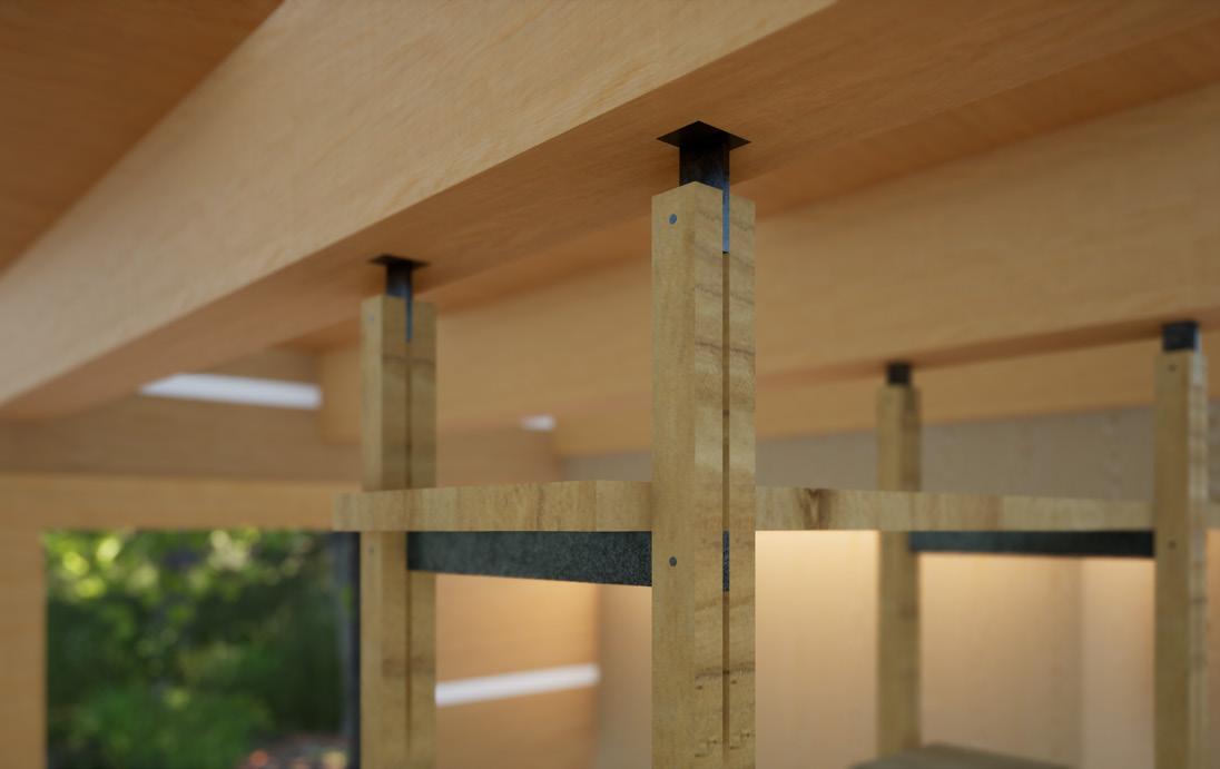
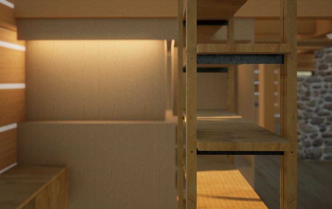
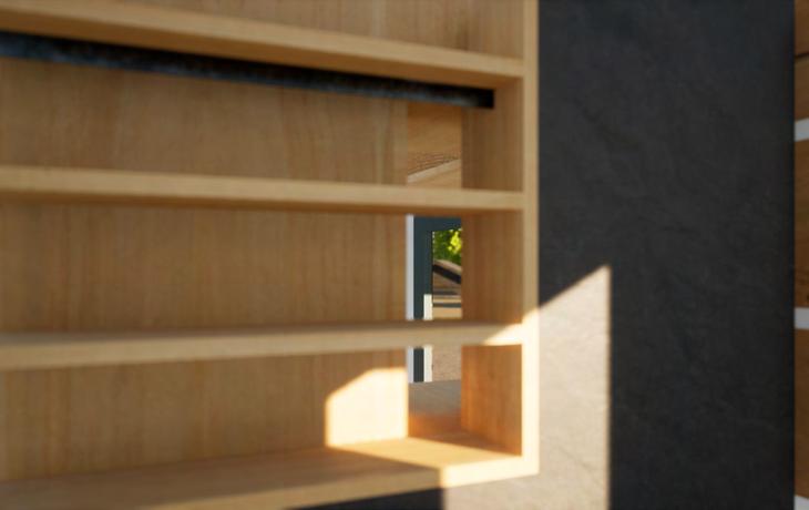
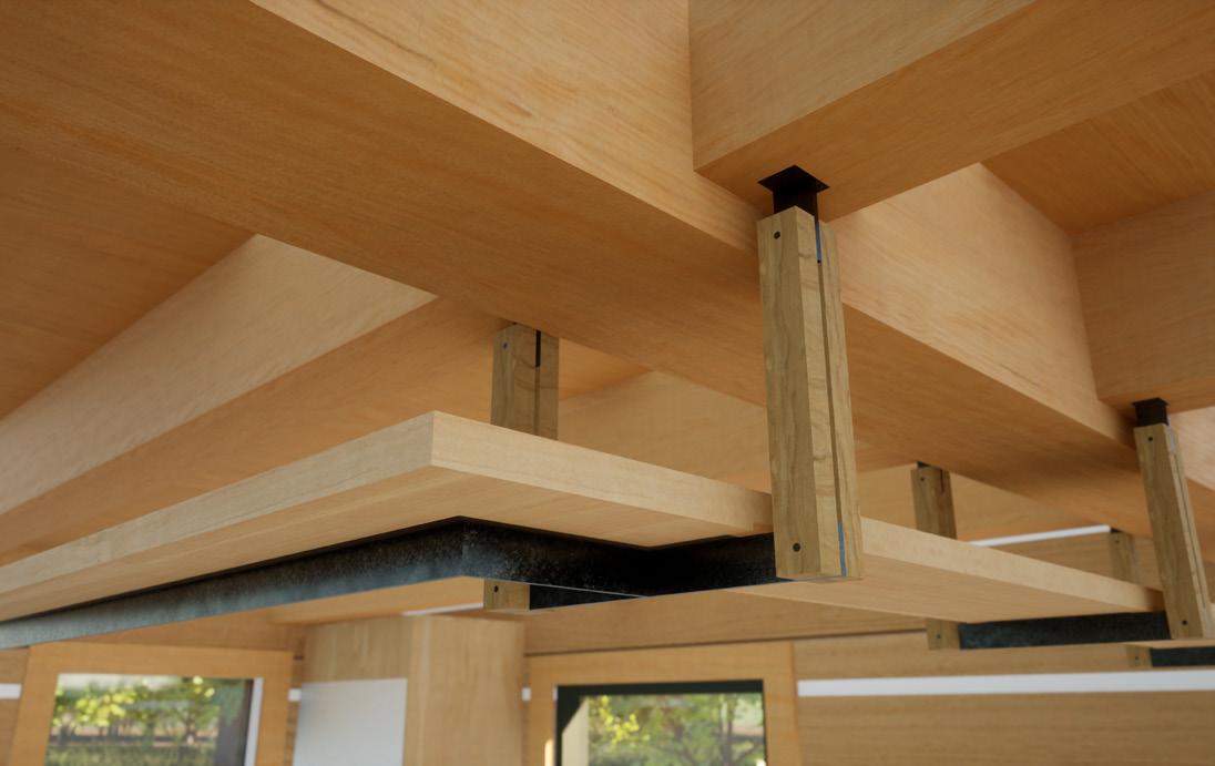
38 1 FIRST FLOOR INTERIOR PLAN 3/8"=1'-0" DINING 105 GREAT ROOM 104 REFER TO 1/A201 FOR SUNROOM AND REAR DECK PLAN E A202 SCOPE OF NEW WORK SHOWN WITHIN WORK ONLY. EXTERIOR WALLS SHALL REMAIN EXCEPTION FOR ANY NECESSARY PATCHING WHICH CONTRACTOR WILL EXECUTE
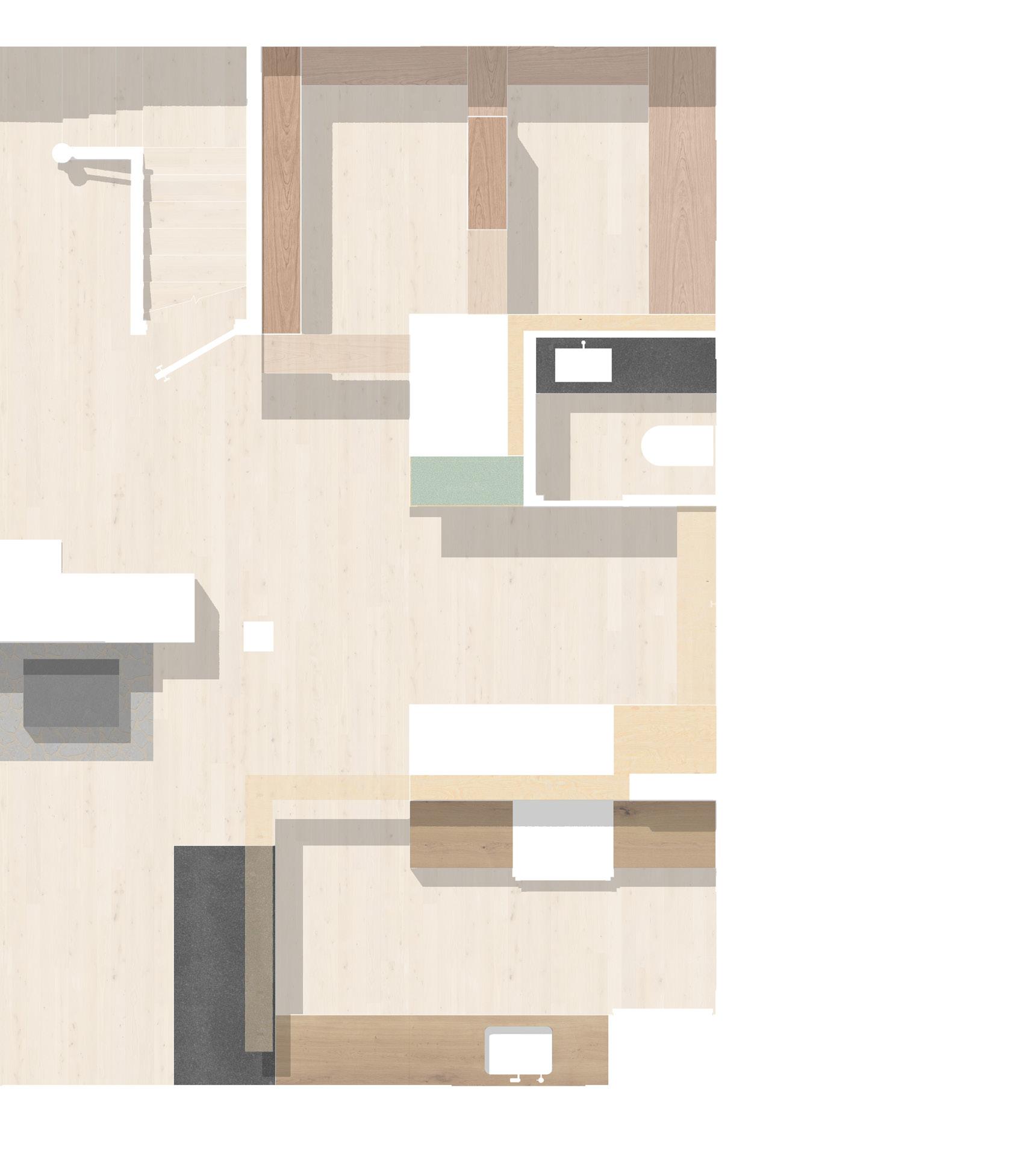
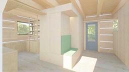
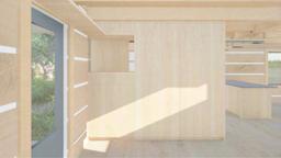

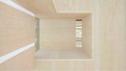
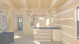
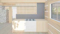
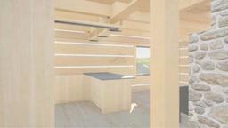

39 UDETSET DRAINSTATUS DATE ISSUESANDREISIONS STRUCTURAENINEER IEFFERSTRUCTURAENINEERIN ERRARDSTREETEAST TORONTOONACANADA OFFICE IEFFERCA DRAN CHECED ACROOISRE INE RAENNAONNHE A FIRSTFOORINTERIOR AN FOYER 101 OFFICE 103 KITCHEN 106 FIXT 101A POWDER 102 FIXT 101B FIXT 106A APP 106A APP 106B OFFICE 103: · MWK 103A: MWK DESK WITH UNDER COUNTER STORAGE AT NORTH AND SOUTH. WOOD SPECIES: PINE. · MWK 103B: MWK LOW CABINET. WOOD SPECIES: PINE MWK 103C: FULL HEIGHT MWK SHELVES ABOVE BASE CABINET. ATTACHED TO ABV JOIST WITH CUSTOM STEEL BRACKET. WOOD SPECIES: PINE AND FLAT SAWN BLACK ASH. · MWK 103D: FULL HEIGHT MWK SHELVES ABOVE BASE CABINET. WOOD SPECIES: PINE. · MWK 103E: CANTILEVERED MWK SHELF AT 7'-0" A.F.F. (WOOD SPECIES: FLAT SAWN BLACK ASH) CANTILEVERED FROM ABV RAFTER BY CUSTOM ANODIZED STEEL BRACKET. NOTE: MWK DESCRIBED INDIVIDUALLY FOR CLARITY ONLY. MWK INTENDED TO PERFORM AS UNIFIED SYSTEM. POWDER 102: · EXT WALLS OF POWDER 102 WALLS CLAD IN MWK FLAT SAWN BLACK ASH PANELS. · FLUSH MWK FLAT SAWN BLACK ASH PANEL DOOR USING TECTUS OR SOSS HINGE. MWK 102A: INTEGRATED STONE SINK AND COUNTERTOP WITH 7" TURN DOWN EDGE. FLAT SAWN BLACK ASH BASE CABINET. EXG ROUGH LOCATIONS SHALL REMAIN INTACT. DO NOT MOVE. TADELAKT FINISH WALLS, COLOUR TBD KITCHEN 106: · MWK 106A: SALVAGED PINE COUNTERTOP OVER PINE BASE CABINET. STONE BACKSPLASH W/ FLAT SAWN BLACK ASH SHELVES ABOVE. EXG PLUMBING ROUGH INS NOT TO BE RELOCATED · MWK 106B: SALVAGED PINE COUNTER OVER PINE BASE CABINET. LOWEST SHELF AT NORTH WALL OF KITCHEN TO BE SET FLUSH WITH T.O. MWK 101B NICHE ABV DRESSER CABINET. WOOD SPECIES: FLAT SAWN BLACK ASH. · MWK 106C: STONE ISLAND COUNTER OVER PINE BASE CABINET. · MWK 106D: CANTILEVERED FLAT SAWN BLACK ASH SHELF AT 7'-0" A.F.F. CANTILEVERED FROM ABV RAFTER BY CUSTOM ANODIZED STEEL BRACKET. NOTE: MWK DESCRIBED INDIVIDUALLY FOR CLARITY ONLY. MWK INTENDED TO PERFORM AS UNIFIED SYSTEM. ENTRY 101: · MWK 101A: FLAT SAWN BLACK ASH WALL MOUNTED SHELF AT HEADER OF DOOR. · MWK 101B: FULL HEIGHT MWK CLOSET W/ ADJACENT MWK DRESSER CABINET WITH NICHE ABOVE IN FLAT SAWN BLACK ASH. MWK 101C: FULL HEIGHT MWK CABINET W/ ADJOINING BENCH IN FLAT SAWN BLACK ASH. DRAWER STORAGE BELOW BENCH. NOTE: MWK DESCRIBED INDIVIDUALLY FOR CLARITY ONLY. MWK INTENDED TO PERFORM AS UNIFIED SYSTEM. MWK 103A MWK 103B MWK 103C MWK 103D MWK 103E MWK 106A MWK 106D MWK 106C MWK 106B MWK 101B MWK 101A MWK 103C MWK 103B MWK 101C MWK 103C MWK 103B MWK 103D MWK 103C MWK 103B CUSTOM STEEL BRACKET DETAIL ATTACH MWK 103C PARTITION SHELF TO CEILING JOIST W/ CUSTOM ANODIZED STEEL BRACKET · JOIN MWK 103C PARTITION SHELVES TO VERTICAL SUPPORT W/ CUSTOM ANODIZED STEEL FLANGE MWK 101C MWK 101C MWK 102A MWK 101C MWK 101C MWK 101C MWK 101C MWK 101A MWK 101B MWK 103D MWK 103D MWK 103C MWK 103C MWK 101B MWK 101B MWK 101A MWK 106D MWK 106C MWK 106A MWK 103A MWK 106D MWK 106C MWK 106B MWK 101B MWK 106A MWK 101B MWK 106D 4'-0" A.F.F. MWK 103E MWK 106C MWK 106D MWK 101B NICHE OPENING FROM FOYER BENCH TO OFFICE NICHE OPENING FROM FOYER TO KITCHEN CUSTOM STEEL BRACKET DETAIL · ATTACH SHELF TO CEILING JOIST W/ CUSTOM ANODIZED STEEL BRACKET NICHE OPENING FROM KITCHEN TO FOYER BLACK ASH BLACK ASH PINE BLACK ASH PINE BLACK ASH BLACK ASH PINE PINE BLACK ASH PINE BLACK ASH BLACK ASH BLACK ASH BLACK ASH BLACK ASH BLACK ASH BLACK ASH PINE PINE PINE BLACK ASH PINE MWK 103C BLACK ASH PINE BLACK ASH PINE BLACK ASH PINE PINE BLACK ASH PINE 13'-5" SHEVLES 1'-2" BASE CABINET 4'-11" SHELVES 1'-2" BASE CABINET 4'-2" DESK 8'-5" POWDER 4'-5 1/4" SHELF ABV DOOR 5'-10 1/4" CLOSET 2'-10 1/2" OPENING TO OFFICE 6" POWDER 5'-2 5/8" 8'-6" 5'-8" SHELVES 1'-9 1/2" CLOSET 2'-0 1/2" BENCH 1'-6" LEDGE 6" 4'-9 3/4" COUNTER 2'-0" SHELF 9 1/4" CLOSET 2'-0 1/2" CLOSET 6'-0" 9'-0 1/2" SHELF OPENING 6'-6" NICHE 2'-0 1/2" 9 1/4" COUNTER 2'-0" 4'-4" COUNTER 2'-1" 30'-8" 16'-0" 3'-0" 9'-10" 7'-1" CABINET 2'-1" OPENING 8" SHELVES 3'-10" 9'-0 1/2" REFER TO 2/A201 FOR FRONT ENTRANCE PLAN A A202 A B C D E F G B A202 C A202 D A202 F A202 G A202 DESK 2'-0" 2'-6 1/2" DRESSER AND NICHE 3'-0 1/2" DASHED LINE. INTERIOR REMAIN UNALTERED WITH PATCHING AND/OR REPAIR,
Sunken Kindergarten
Site: Glen Morris Street and Huron Street, Toronto
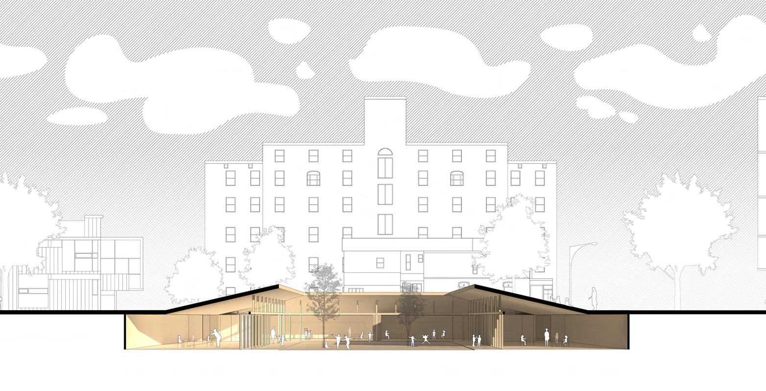
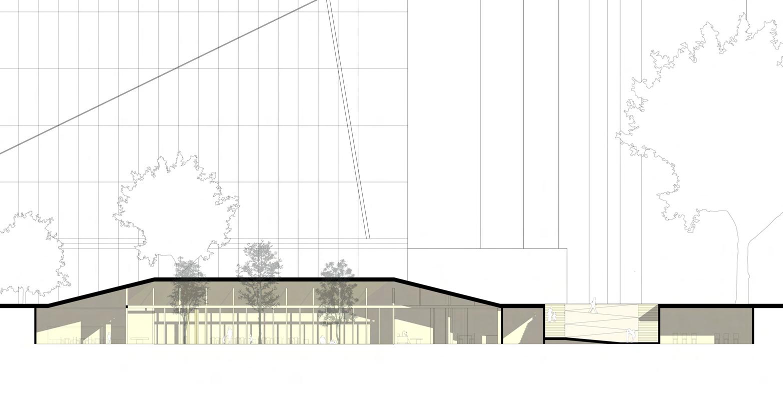
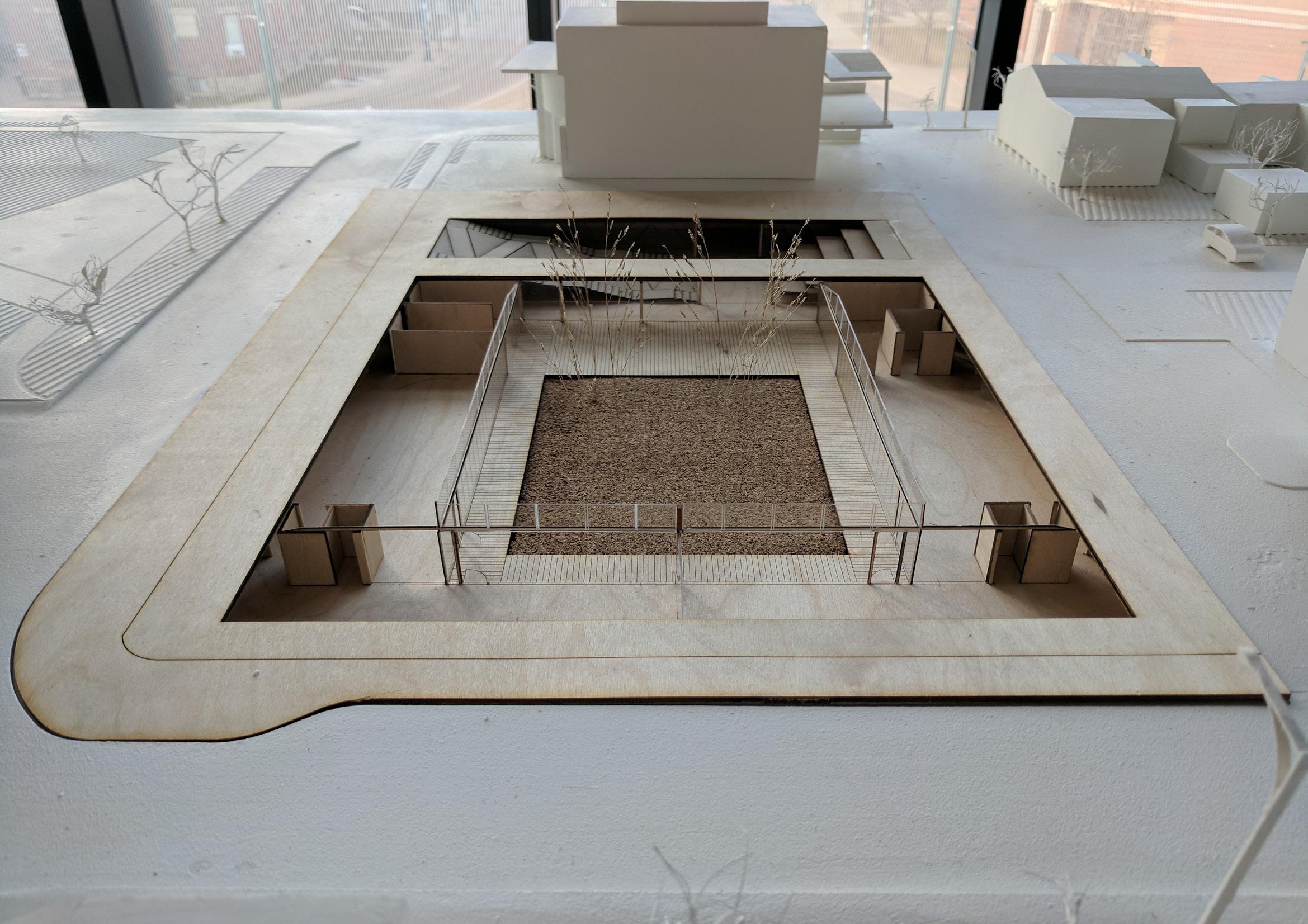
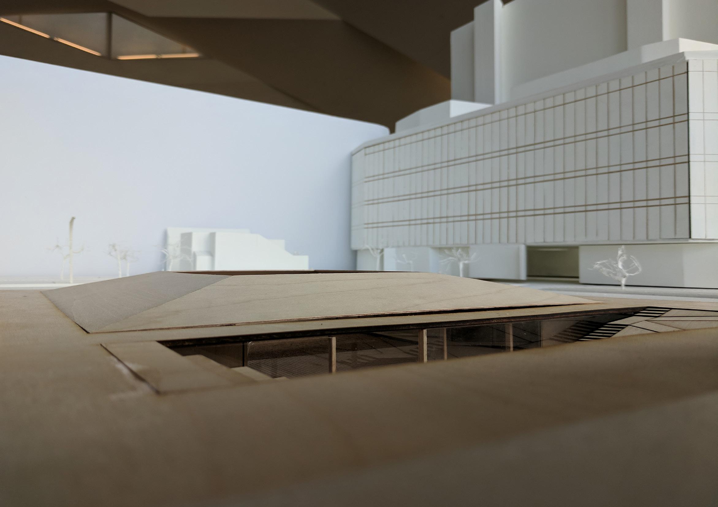
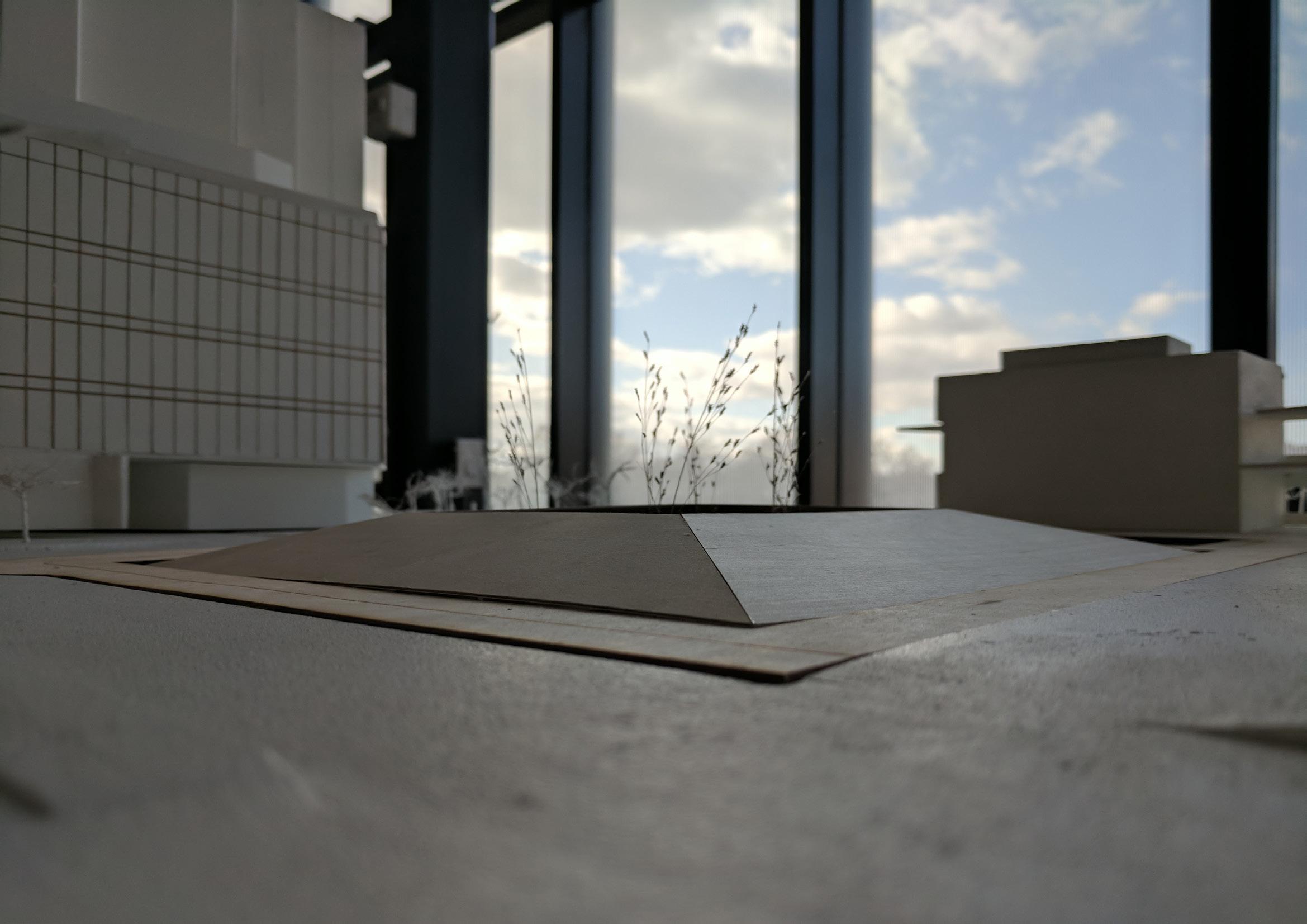
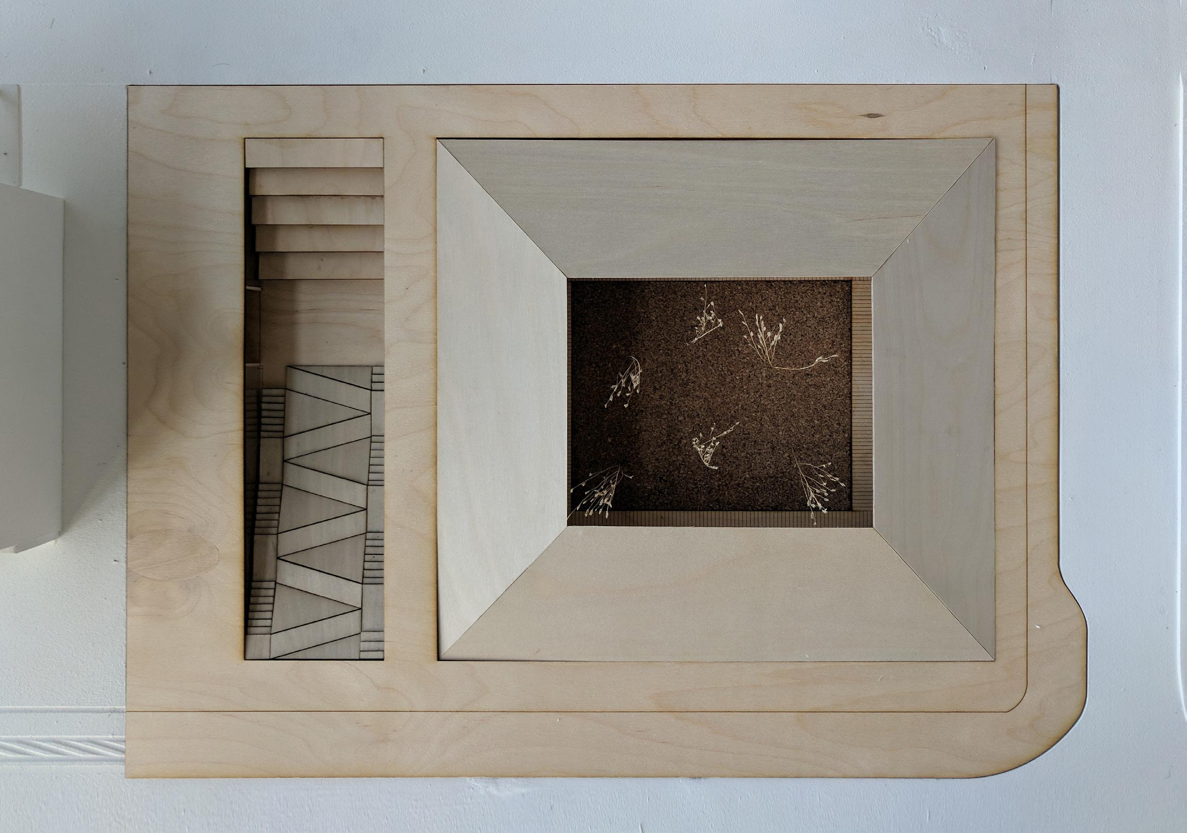
The project brief called for a kindergarten of four classrooms, capable of holding twenty students each. Due to the scale and complexity of the adjacent buildings, a low, geometric structure was chosen to contrast the surrounding buildings. The low pyramid, with classrooms sunk into the earth, was designed to provide safety and privacy without relying on fencing. Further, the central courtyard allows ease of access to the outside to all four classrooms, while providing covered and uncovered play areas.
40
T a a b b
42
43
175: Laneway Suite
Site: Toronto, Ontario
Works Office of Brian O’Brian Architect
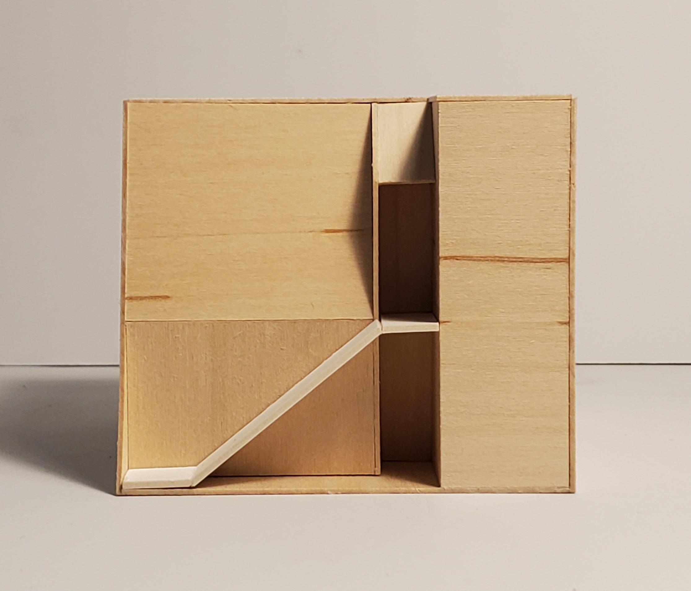
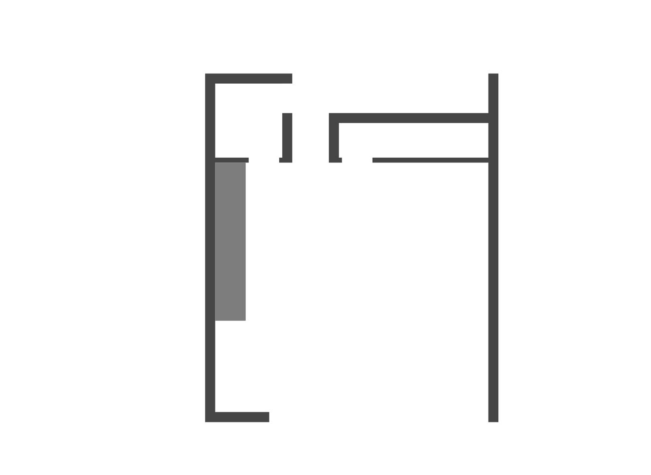
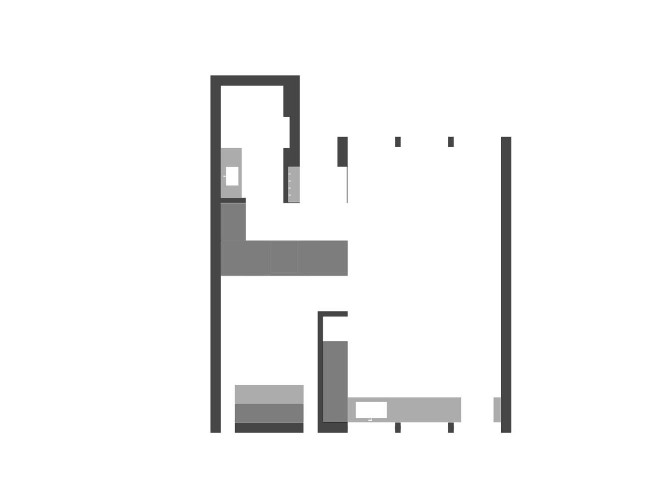
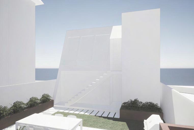
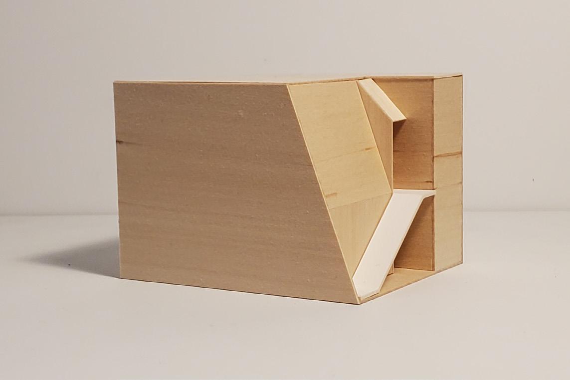
The client, in anticipation of their two children leaving for university, requested a proposal for a rear laneway suite. This proposed laneway suite consists of a ground floor garage, storage, and mechanical space and second floor single bedroom residence.
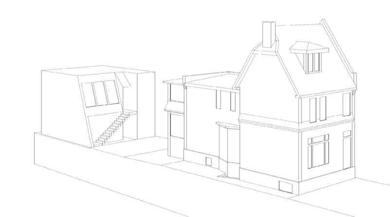
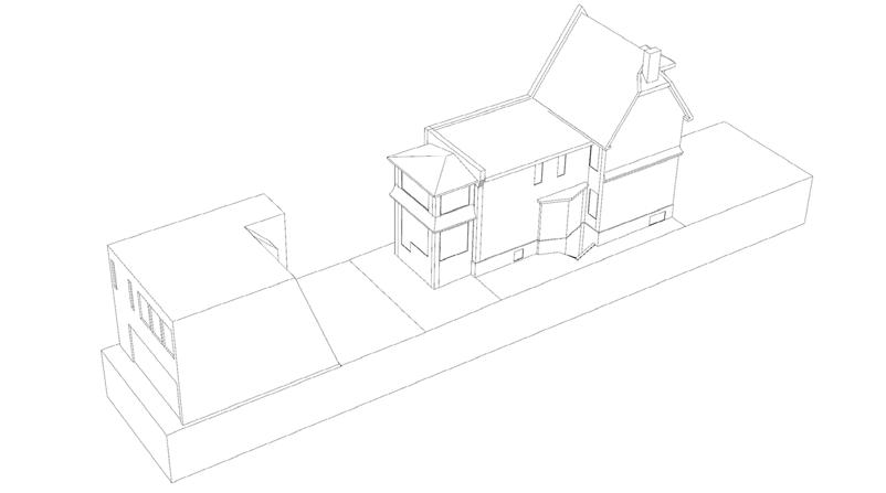
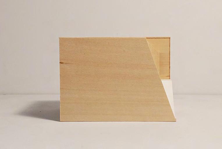
The City of Toronto imposes several constraints on the size and form of laneway structures, including height, length, width, dormer width, an angled facade, and an offset from the main residence. In designing the form of the laneway, these constraints were used to inform, but not dictate, in order to create an original building.
The residence space consists of a bedroom, bathroom, living room, and kitchen. Millwork holding appliances, storage spaces, and closets divide these spaces to ensure that none of the limited space is wasted.
44
Bottom: Zoning diagram, render and model
Left: Model
Top: Ground and first floor plans 1/16” = 1’0”
45 PROPOSED WITH EXG OUTLINE 45° ANGULAR PLANE BEGINNING AT 4.0M ABOVE GRADE DORMER AT MAXIMUM 30% OF TOTAL WIDTH DASHED LINE INDICATES EXG CARPORT, LANDSCAPE, AND HOUSE DASHED LINE INDICATES MAXIMUM EXTENTS OF LANEWAY ENVELOPE PER BY-LAW DASHED LINE INDICATES EXG KITCHEN AREA DASHED LINE INDICATES PROPOSED LANEWAY KITCHEN AND LIVING AREA CONDITION 3 DORMER AT MAXIMUM 30% OF TOTAL WIDTH DASHED LINE INDICATES EXG CARPORT, LANDSCAPE, AND HOUSE DASHED LINE INDICATES EXG KITCHEN AREA DASHED LINE INDICATES PROPOSED LANEWAY KITCHEN AND LIVING AREA PROPOSED WITH EXG OUTLINE 45° ANGULAR PLANE BEGINNING AT 4.0M ABOVE GRADE DORMER AT MAXIMUM 30% OF TOTAL WIDTH DASHED LINE INDICATES EXG CARPORT, LANDSCAPE, AND HOUSE DASHED LINE INDICATES MAXIMUM EXTENTS OF LANEWAY ENVELOPE PER BY-LAW DASHED LINE INDICATES EXG KITCHEN AREA DASHED LINE INDICATES PROPOSED LANEWAY KITCHEN AND LIVING AREA PERSPECTIVE DRAWINGS OF ENVELOPE 24'-1 1/4" 18'-0" 20'-6" 6'-1" FIRST FLOOR PLAN 1/4” = 1’-0” 24'-1 1/4" 28'-8" 12'-3 1/4" 22'-1" 7'-9" 11'-9" 3'-0" 9'-0" 3'-3"
Erosion Machines
Team members: Niko Delic, Simba Mai, Chris Lam
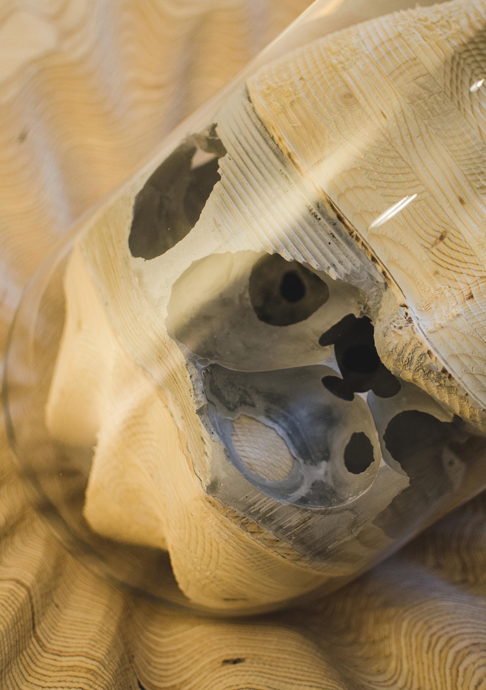
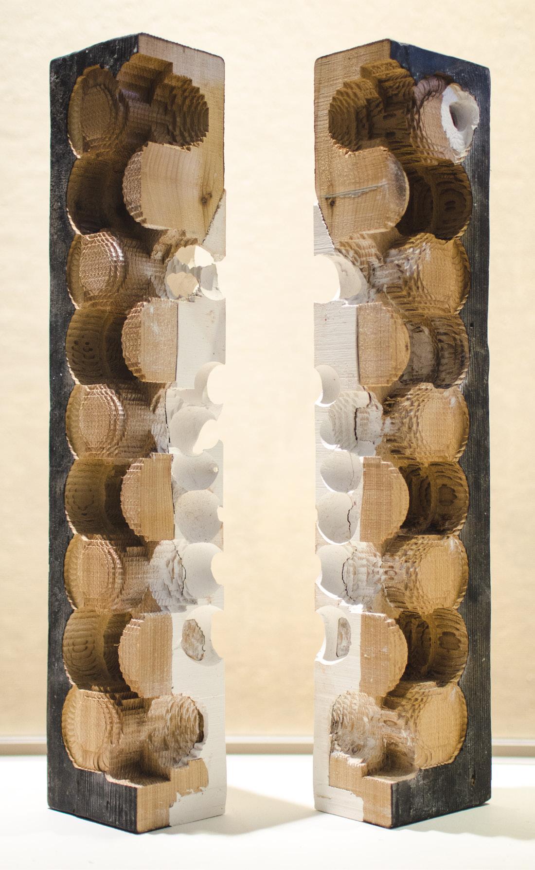
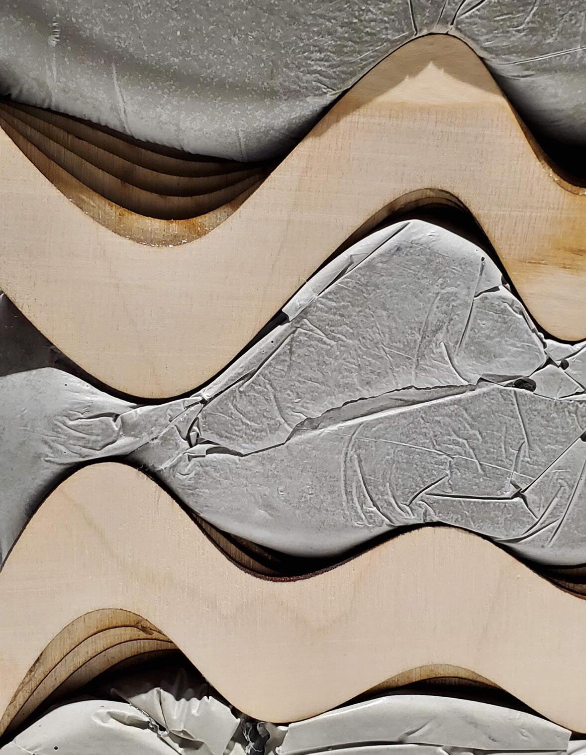
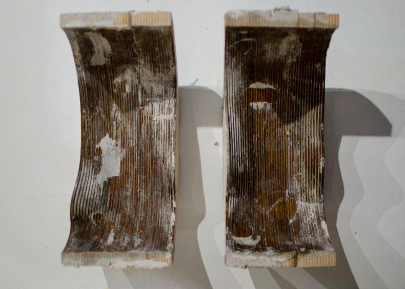
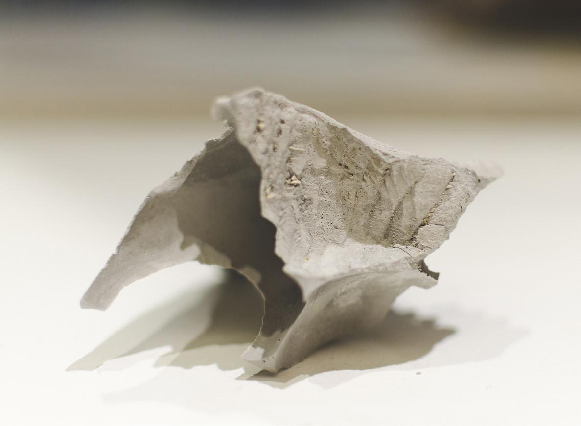
The erosion machines team created a series of sculptural pieces using a mixture of digital and hand modelling. Through experimentation, the team combined concrete, plaster, balloons, plastic bags, lasercut forms, burnt cedar, and CLT to create objects which combined hand craft and digital fabrication.
We experimented with how concrete would react being injected in balloons, around water filled balloons, and squeezed into plastic bags, how plaster, cedar, and CLT withstood CNC milling, and the combination of these experiments resulted in a final model contained within a glass dome.
46