4 minute read
A Unique “Vintage” Tractor


by Jack Clover
It was way back in 1965 when my new wife and I bought an old rectory. Well they were cheap in those days, few were fool enough to take them on.
It was situated in a couple of acres of rubbish. Happily, there was a man with a JCB digger nearby who quickly turned it into rough soil.
Now what? It needed smoothing a bit, and once grass (and more rubbish) had established itself it would need cutting. I had an 18 inch push mower but that tired me out on the little bit that was already grass. What I needed was a ride-on.
The market was searched. One I could afford was built to the standard of a child’s pedal car with an engine the same size as my push job, it had a 24 inch cut and could travel at 5 mph (on concrete) but not both at the same time! Anything more substantial was way beyond my pocket, and still a bit of a toy.
So I decided to make one out of scrap, no engineering training, but what could I lose?
An old ark welder, and even older lathe was purchased, and I started collecting bits from scrap bins.
Two discarded lengths of 4 X 2 X 1/4 channel with three pieces of 4 inch steam pipe welded between them made a strong chassis, a good start.
A local scrap yard provided a Ford Popular front axle and steering gear. The axel was centre pivoted on a couple of plumber block bearings, the steering column and box mounted on the side rail. The hubs were fitted with Mini wheels with added spokes. The rear axle was of unknown origin and mounted directly under the side rails. It had 16 inch wheels suitable for lugged dump truck tyres.
For an Engine I choose a Morris Minor 1100, plentiful (then), efficient with readily available and cheap spares.
Car gearing would be no use for a tractor, of course, so the Morris gearbox was sawn off the bell housing and a small diameter sprocket fitted in its place. A prewar Alvis all synchromesh gearbox was purchased for £3, an ideal unit, unbreakable, and with drive flanges at both ends, so a large diameter sprocket could be fitted to the input, with the output coupled to the differential.
As the gearbox had to be centrally mounted, the engine was placed to one side to give room for the chain reduction unit between them. The radiator was mounted in line with the side rail on the opposite side to the engine with an electric cooling fan. The rear end was fitted with tow hitches for trailers, rollers, or a heavy chain for pulling out small trees and such like.
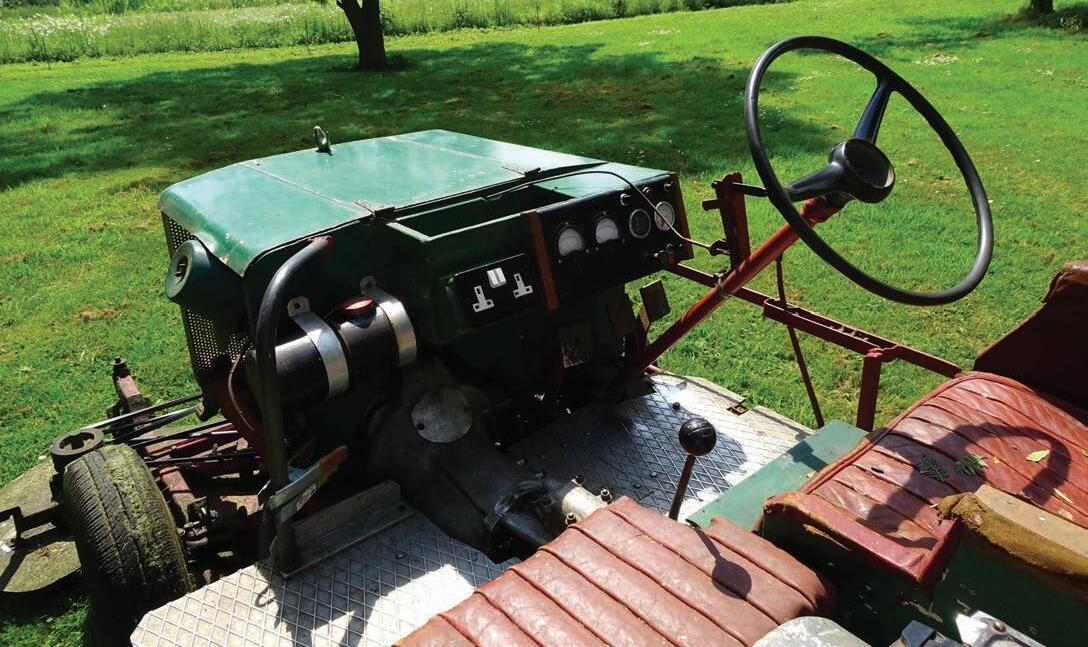
With the addition of a seat, floor, fuel tank, controls and instruments I now had a mobile small tractor. However, to be useful it needed a power take-off and mowers.
A three-lane pulley with outrigger bearing was fitted to the front of the engine crank beyond the fan/dynamo pulley. A line shaft was installed on the other side of the chassis stretching from beyond the front to the rear, with another three-lane pulley in line with that on the engine. Between the two a flat pulley on its own bearings, and connected via cranks and rods to a lever beside the seat, could tighten the otherwise loose belts and act as a clutch.
Initially, the line shaft drove a compressor, which could control a front mounted dozer bucket or scraper to level the earth, as left by the JCB.
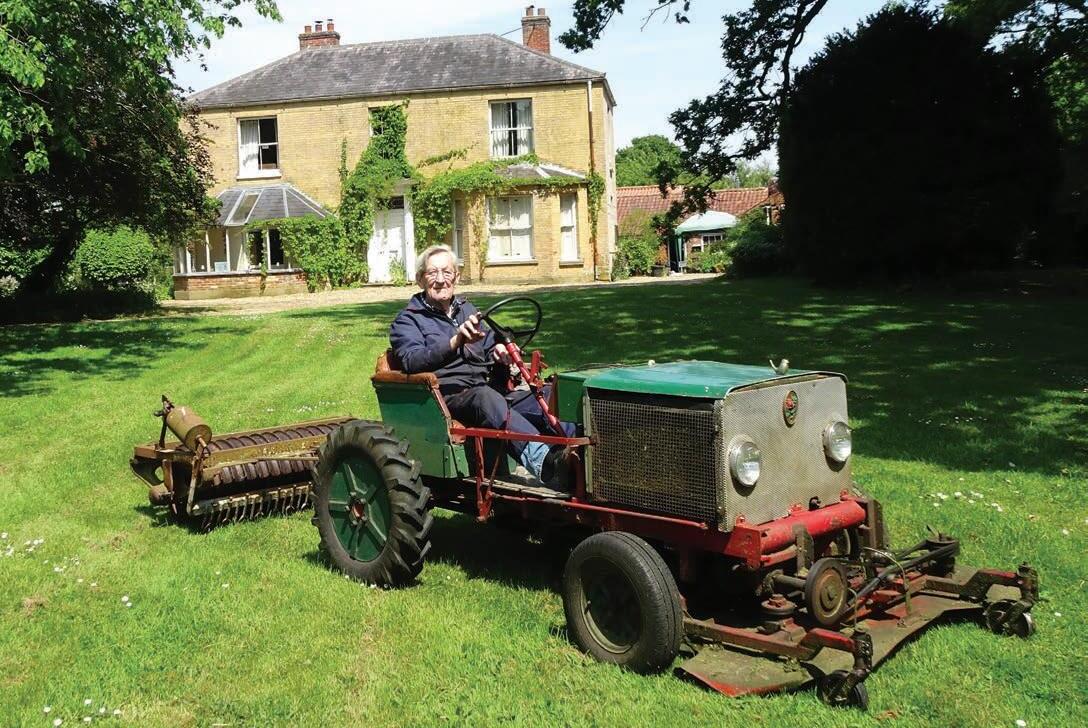
Meantime I was working on a front mounted cutter unit, as it turned out, the most difficult part of the project. It was to contain three 20 inch rotary blades in a V formation, giving about a 55 inch cut, mounted on the front axle. The problem was the entire unit had to follow the ground contours, both side to side, and fore and aft and yet keep correct belt tension. Despite the levelling exercise, it was no nice level tennis court! Further, the line shaft was horizontal, and the cutter spindles, vertical, three of them. Two units were scrapped because the main drive belt kept coming off! Number three ended up with two self-steering castor wheels in front whilst the quarter twist belt passes over two flat faced guide wheels, one fixed on the belt drive side, the other on a spring-loaded pillar on the return side. The primary cutter blade has a three-lane pulley, one for the main drive, the other two to drive the other cutters. I could not obtain any caster wheels strong enough, so had to make them as well.
For over fifty years now, the mower has worked well and reliably, and used less petrol per acre than one of those bought ones. It will outlast me, I think.
About twenty five years ago, I did, however, make a few changes. I had been cutting in 1st or 2nd gear but would have preferred to use 3rd or 4th, so lower gears were available for more difficult jobs. Further, I had acquired a 240 volt, 3KW alternator which, mounted on the tractor, would enable the use of electric tools remote from the house. At the same time, it seemed a good idea to overhaul the engine.
The latter was straightforward and inexpensive. New pistons, bearings, valves, chain, oil seals and gasket set were less money than a head gasket for the Alvis 3 litre I was working on at the same time!
The 3kw. alternator was mounted at the rear, beside the seat, driven from the rear end of the line shaft. Fuses, 13 amp sockets, volt and ammeter completed the job.
Changing the gearing was more difficult and needed a double chain reduction with two chains and four sprockets. The Alvis gearbox was removed and replaced by an original Morris box attached to the bell housing. The new chain reduction was then placed between the gearbox output and the differential of the rear axle. Bearing in mind the increased torque, this was replaced by one from an Alvis TA14, a much stronger unit.
The whole job showed a profit because the Alvis gearbox was sold for £700!
The lower gearing has proved its worth on occasions, and the alternator was even found useful during a long power cut.


