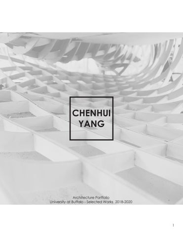
CHENHUI YANG
Architecture Portfolio University at Buffalo - Selected Works 2018-2020
1
Table of Contents 01
Play / House
02
Eco-Mass
Senior Studio, Fall 2020
Junior Studio, Fall 2019
03
Contour Envelope Junior Studio, Spring 2020
04
Children’s Museum Sophomore Studio, Spring 2019
05
Menefee Cabin Construction Technology, Spring 2020
06
Kitsap County Administration Building Construction Technology, Spring 2020
1
CHENHUI YANG (NICK) Education
Cell: (718)-915-3637 – chenhuiy@buffalo.edu
__________________________________________________________________________________________
2018 - 2021
University at Buffalo - Bachelor of Science, Architecture, Buffalo, NY
2016 - 2018
New York City College of Technology - Bachelor of Architecture, Brooklyn, NY
2012 – 2016
Edward R. Murow High School, Brooklyn, NY
Work Experience
__________________________________________________________________________________
09/2018 - 02/2020
University at Buffalo On-Campus Federal Work Study Global Gender and Sexuality Study Department – Buffalo, NY Organizing mails and folders for the department, delivering documents to other offices, assisting with inventory.
05/2018 - 09/2018
Restaurant Waiter Liuyishou Hotpot – Princeton, NJ Greeting customers, explain menu to customers, deliver food and drinks. receive customer payment and phone orders, daily side works.
05/2016 - 02/2017
Cashier, Office Worker Ru Yi Service INC – Brooklyn, NY Greeting customers, received customer payments, assisted customers on selecting items, processed customer returns, explain products and services in detail, answered customer phone calls promptly in an appropriate manner.
06/2015 - 09/2015
Restaurant Waiter Muilan Restaurant – Canton, GA Greeting customers, communicate with customers in an appropriate manner, answer phone and online order, receive customer payments, pack food for delivery order, serve food for dinein customers, daily side works.
Softwares
__________________________________________________________________________________________
Autodesk Autocad Autodesk Revit
Adobe Photoshop Adobe Illustrator
Rhinocero V-ray for Rhinocero
Hand Drafting
Adobe Indesign
Lumion
Languages
_________________________________________________________________________________________
English
Skills
Chinese Mandarin
_______________________________________________________________________________________________
Critical Thinking Wood Work
Presentation Model Making
Detail Drawing CNC Milling
2
Play / House University at Buffalo Senior Studio, Fall 2019 Instructor: Annette LeCuyer Partner: Yiyu Zhang
PLAY/HOUSE addresses the urgent need for affordable family housing in Brooklyn, also providing both family dwellings and a range of amenities for children. A curvilinear cut through the site forms a public pedestrian path at ground level, flanked by public facility that connects Kent Avenue to the a public garden. On upper floors, three residential buildings are comprised of two-story family units, which can be entered via interior circulation on the lower floor and exterior circulation on the upper floor. The three buildings are linked by curvilinear circulation routes, which also serve as play space for the children on the site, expanding in places to accommodate both quiet and active gatherings. The outer facades of the residential buildings are civic buffers between the private dwellings and the public street, with planted terraces to provide a visual screen as well as summer solar shading.
3
4
Mrytle Village Green Garden
Playground
Main Entrance
Mail Room
Gym
Market
Kent Ave
Restaurant
Laundromat Secondary Entrance
0
25
Ground level
50
Ope
Ground level
100
5
Daycare Center
Parking
Opening t
N
Site
Extruded block
Setbacks
the block
Curvelinear form
Public park & extenson
en space
Curvelinear circulation
Final Scheme
6
7
8
9
10
11
12
ECO-MASS University at Buffalo Junior Studio, Fall 2019 Instructor: Randy Fernando Partner: Paul Owusu
This proposal began with a combination of two concept ideas from a study of buoyancy which is based on the learning from building a full-scale physical vessel model. The first concept was inspired by the idea of applying textured material on a walking path to create different walking experiences in a space while the second concept is to support a heavy mass using light frames. In further development during the process of physical modeling, the idea of creating a walking experience using different materials was tested using a variety of materials like wood, fabric, canvas, plastic warp, industrial marine warp, and cement. The concept of supporting heavy mass with light frames was resolved with the strategy of waffle grid using wooden light frames and casting of cement on the top. As an addition design learned from the casting strategy of cement, the heavy mass is reconsidered to become an extension of earth and a fully accessible public park to achieve the design of an ecological system on top of the building.
13
14
Concept: Materiality
Wire & Canvas joints
Wood Density: 680 kg/m^3
Canvas Density:Varies, less than water
Wooden frame notch joints
Encaustic Wax Density: 900kg/m^3
Applying Wax
15
Boat sheating
Wire & Wood joints
Multi-layers of wax
16
DN
OPEN TO BELOW
UP
PUBLIC SPACE CORRIDOR
CORRIDOR INSIDE MASS
ENTRANCE VESTIBULE
ENTRANC TO LOBBY UP
RAMP DOWN
WALKPATH RAMP DOW
ENTRANCE
MULTI-USE EVENT SPACE
W.C.
LARGE CO-WORKING SPACE
DN
W.C.
COMM W/ SEA
RESEARCH LAB
FLEXIBLE CLASSROOM /METTING
1st Floor N
N
FIRST FLOOR PLAN SCALE: 3/32” = 1’-0”
17
OPEN TO BELOW LOBBY
EXHIBITION GALLERY
CE Y GIFTSHOP
WALKPATH RAMP DOWN
WN
ENTRANCE TO COMMERCIAL KITCHEN
W.C.
W.C.
MERCIAL KITECHEN ATING
CONFERENCE ROOM STAFF OFFICE W.C.
DN
W.C.
UP
2nd Floor N SECOND FLOOR PLAN SCALE: 3/32” = 1’-0”
3rd Floor N THIRD FLOOR PLAN SCALE: 3/32” = 1’-0”
18
19
35' - 0"
-15' - 0"
20
21
22
CONTOUR ENVELOPE University at Buffalo Junior Studio, Spring 2020 Instructor: Elaine Chow
This project investigates the concept of wind to create a wind barrier that blocks heavy wind from different directions to an open public plaza. study of laufmachine that was constructed from layers of cardboard pieces. The idea of contour layers is to create the movement of flow and continuity. As well as positive/solid and negative/ void space. As the project continued to develop, the concept of contoured tectonics and the wind barrier was introduced at the public plaza to achieve an open area of public gathering space with stepping and seating in front of the building. Besides, the perimeter of the first level concaves inward to express the openness of the least wind-receiving direction.
23
24
Concept: Contour
Re-purposed Re-purposed bicycle bicycle frame frame (steel) (steel)
Body Structure Body structure (cardboard (cardboardwhite) painted pained white)
CC
Stacking cardboards Stacking the cardboard allows for each piece to hold up to 350 lbs, making the Laufmaschine strong and sturdy.
CC CC
Resistance
The flute of the double wall cardboard is type C-flute. This allows crushing resistance and strength.
Re-purposed Re-purposed bicycle bicycle wheel wheel Insulation The alternating direction of the layered cardboard provides insulation against variations or temperature.
Air flow
The alternating C-flute layers provide spaces for air to flow through to avoid wind resistance.
25
WIND ANALYSIS Concept: Wind Wind Direction WIND DIRECTION
N NE
NW
Dear
50(%)
Wi
SE
nte
S
We st
- Ja
rW
n, F eb,
St born
30 40
SW
t ara S Niag
E
10 20
190 way High
W
e St Bridg
ind
No v, D
ec
WIND Speed SPEED Wind
SITE
Dec
Jan
t hS ris a P
Nov Oct
erSou th W -O inct d
Feb Mar
m Su
al
an
Aug
6
20 ft
26
May Jul
0
May, Southwest - Mar, Apr, Jun, Jul, Aug, Sept
kC
Apr
10 12 14(mph)
N
Summer Wind
oc
Sept
m
kR
ac
Bl
2 4 6 8
Jun 60 ft
38’
38’
38’
Form of laufmachine 18’
18’
18’
18’
Required 18 feet space
W
S
W
N
N E
N
N
N
E
S
38’
E
max allowable height : 40 feet allowable max allowable max height : 40 feetheight : 40 feet
N
cutdirection corner atofthe direction cut/ corner of lightatwind the direction / positive of vs.light wind / positive vs. cut corner at the light wind positive vs. negative space negative spacenegative space
Height: 40 feet
tectonic form of laufmachine tectonic form of tectonic laufmachine form of laufmachine
W
W
E
allowable 40 feet allowable height : 40 feet max allowable max height : 40 feetheight :max
38’
W
38’
S
tectonic form of tectonic laufmachine form of laufmachine tectonic form of laufmachine
W
S
S
S
E
E
Cut corner
cut corner at the direction of light wind / positive vs. cutdirection corner atofthe direction of light wind cut corner at the light wind / positive vs. / positive vs. negative space negative spacenegative space
18’
18’
Contour form
creating contour form creating / 18contour feet space multipurpose level form /space 18 feet multipurpose space creating contour level form / 18 level feet multipurpose as requirement as requirementas requirement
variety size of contour variety form size of contour form variety size of contour form
tectonic form tectonic form
creating contour level form / 18 feet multipurpose space creating contour form / 18 feet space multipurpose space creating contour level form / 18 level feet multipurpose as requirement as requirementas requirement
variety size of contour form variety size of contour form variety size of contour form
tectonic form tectonic form
tectonic form
Tectonic form
tectonic form
26
Underground parking
27
1st level
2nd level
3rd level
E-W Section
28
Columns Beams
Egress Wheel chair
Inverted Tees Double tees
Circulation
Supply Return Service units
Radian panel Metal panel Service units
Mechancial system
29
Structure
Radiant heat system
PANEL
GUARDRAIL
METAL PANEL FACADE
RIGID INSULATION
NTOUR GETATION
TRIPLE GLAZED GLASS
G
STRUCTURAL BEAM
LASS
N THE INNER ON TO G AND
ANEL LTIPLE NSULATION
ETE NG AT THE
PRECAST CONCRETE DOUBLE TEE PRECAST INVERTED TEE STRUCTURAL SYSTEM DIAGRAM
METAL PANEL FACADE PROVIDES SHADING STRATEGY TO INTERIOR
ETE DOUBLE STOM PREE
RADIANT HEAT SYSTEM HEATING/COOLING TUBES
TION SLAB MENT BARS TION WALL
ECTION ”= 1’-0”
RADIANT HEAT SYSTEM DIAGRAM
30
31
32
CHILDREN’S MUSEUM University at Buffalo Sophomore Studio, Spring 2019 Instructor: Jon Spielman
This project investigates the design of a children’s museum located at Buffalo State University, Buffalo, NY, through studies of a variety types of museums and explore the concept idea of “lost and found space.” The scheme initiates with a case study, Memorials to the Murdered Jews of Europe, with the principle of space study in order to gain experience about creating a space that form a scene of feeling in lost. As the project continued to develop, the idea of being lost is established with the repetition of walls in one direction. This strategy created a scene of maze-like space to both control the circulation in the space and programs in the museum.
33
34
ollege
ollege
eC lo Stat Buffa n catio Site lo
Buffalo State Richardson OlmOpen Space Residential Build-
eC lo Stat Buffa n catio Site lo
N W
N E
S
Site
Site resouces
Vision Toward Site
Site Topography Design
35
W
E S
Zoning
th Sun pa lege e Col lo Stat Buffa n catio lo Site
Traffic lege e Col lo Stat Buffa n catio lo te Si
ollege
eC lo Stat Buffa n catio Site lo
N
N
N W
d er win Summ d r win Winte
E S
Sun path
W
W
E
Traffic
E S
S
Wind
exterior walls Exterior walls
Glassglass
interior walls Interior walls
Slabsslabs
36
W.C.
Lobby
UP
3
DN
Exhibition UP
UP
2
DN
Entrance
DN
UP
3
6
Storage
Exhibition
UP
Storage
DN
W.C.
DN
W.C.
Exhibition
Level 3 Plan 1’- 0” = 1/16”
Level 2 Plan 1’- 0” = 1/16”
37
3. Exhibition 4. Admin
5. Multi-purpose room 6. Storage
UP
UP
Porgrams: 1. Entrance 2. Gift shop
DN
DN
Gift Shop
1
3
Exhibition DN
3
UP
Exhibition
Exhibition
3
Exhibition W.C.
W.C.
W.C.
3
Exhibition DN
UP
UP
DN
4
Admin
5
Multi-Purpose Room
38
39
40
Menefee Cabin University at Buffalo Construction Technology, Spring 2020 Instructor: Annette LeCuyer Project: Menefee Cabin Architect: Gregg Bleam Location: Zirconia, NC
This course taught student to understand the detail of structural elements and connections in building construction through the analysis of existing architecture projects. The main objective is to produce a complete set of sectional axonometric drawings followed by detail elements, annotation callouts, and outline specification.
4
3
Menefee Cabin, designed by Gregg Bleam, utilized the advantage of Concrete Masonry Unit façade including resistant to moisture, rot, mold and fire to situated itself high in the North Carolina mountains and surrounded by a variety of local plantation.
2 41
1
Outline Specification 9) Roof
- Cast-in-place concrete lintel with rein forcement bars - 2 x 10 x 2 inches laminated veneer lumber - 2 x 10 wood beams - 6 inches batt insulation
8) Upper level floor
- Air space - Clay flue lining - Cast-in-place concrete sill with double glazing glass - W 12 x 14 steel i-beam - 3 x 10 wood framing at 16” o.c. - 2 inches tongue and groove
4
7) Chimney wall at first level floor - Clay flue lining - Fireproof fill - 8 x 16 x 8 double inner wythe CMU bond beam with 2-#5 horizontal reinforcement bars
6) First level floor
- 2 inches tongue and groove - Plywood web I – joist framing at 16 inches o.c. - 6 inches batt insulation
5) Fireplace opening at first level floor
3
- Clay flue lining - Fireproof fill - Fireplace hearth - 8 x 4 x 4 inches fire brick - 8 inches thick cast-in-place concrete slab with 16-#5 reinforcement bars
4) Chimney wall at ground level floor
- Clay flue lining - Fireproof fill - 8 x 16 x 8 double inner wythe CMU bond beam lintel with 2-#5 horizontal rein forcement bars
2
3) Fireplace opening at ground level floor
- 8 x 16 x 8 outer wythe CMU blocks - Fireproof fill - Fireplace hearth - 8 x 4 x 4 inches fire brick
2) Fireplace below grade
- 8 x 16 x 16 inches CMU blocks inner wythe - 8 x 16 x 12 inches CMU blocks outer wythe
1
1) Foundation at fireplace
- Site cast concrete pad footing at 6 inches
42
Kitsap County Admin Building
7
C
ROOF LE WALL AX 1” = 1 0 1 2 3
Outline Specification
University7.at Buffalo Parapet - Prefinished sheet metal coping type1 Construction Technology, Spring 2020 - Elastomeric watertight reinforcing on Instructor: Annette LeCuyer corners 1/8 inches thick
C
- Pressure treated wood bolted into concrete beam below at slope 1” per foot
Roof Project: Kitsap County6.Administration Building - W16x26 flange steel beam Architect: Miller Hull - Corrugated metal decking - Insulation WA Location: Port Orchard, - ¾ inches thick perlite - Roof membrane - Suspended Act. ceiling
This course taught student to understand the detail of structural elements 5. Second level floor and - Concrete edge beam 1/2 inches per connections in building foot slope w/ construction - #5 reinforcement bars - 8 inches hollow core precast concrete through the analysis of existing plank architecture projects. -The main objective 2 1/2 inches topping slab w/ mesh reinforcement is to produce a complete - Raised set access of floorsectional o/ concrete structure axonometric drawings- R-10 followed by detail rigid insulation @ perimeter, Cont. fin tube radiator on support, Plenum elements, annotation callouts, and divider outline specification. - Suspended Act. ceiling below precast
B
6
concrete plank
A
3
3. Planter Wall designed Kitsap Administration Building, - 10 inches thick site cast concrete wall w/ #5 - reinforcement bars by Miller Hull, situated the central vertical - 4 inches concrete base circulation core along a series of - Earthwith fill - Top of mulch to align w/ top of stepped terraces. The building is oriented cast-in reveal along an east-west4.axis, which First level floorallowed - Concrete beam 1/2 inches per foot full glazing façade slope on the north of the w/ #5 - reinforcement bars R-10 rigid insulation @ perimeter , building for better working light and large Cont. fin tube radiator on support, Plenum overhangs on the south divider to reduce glare.
5
- Vinyl-faced, R-21 batt insulation
2. Planter footing
- 16 inches cast in place concrete strip
footer w/ #5
-reinforcement bars
1. Slab - garage
- 6 inches thick concrete slab at ¼ inches per foot slope w/ #5 reinforcement bars 1.5 inches each way - Vapor barrier - Trench drain
2
A
0 1 2
WALL SECTION 1/2” = 1’- 0”
4
43
FIRST WALL 1” =
7
EVEL XON 1’- 0” 5
Outline Specification 7. Parapet
- Prefinished sheet metal coping type1 - Elastomeric watertight reinforcing on corners 1/8 inches thick - Pressure treated wood bolted into concrete beam below at slope 1” per foot
C
6. Roof
Outl 7. Pa
7
- Pr - El corner - Pr concre
C 6
6. Ro
- W16x26 flange steel beam - Corrugated metal decking - Insulation - ¾ inches thick perlite - Roof membrane - Suspended Act. ceiling
-W - Co - In -¾ - Ro - Su
5. Second level floor
- Concrete edge beam 1/2 inches per foot slope w/ - #5 reinforcement bars - 8 inches hollow core precast concrete plank - 2 1/2 inches topping slab w/ mesh reinforcement - Raised access floor o/ concrete structure - R-10 rigid insulation @ perimeter, Cont. fin tube radiator on support, Plenum divider - Suspended Act. ceiling below precast concrete plank
B
5. Se 5
6
- Co foot slo -8 plank -2 reinfor - Ra structu - RCont. fi divider - Su concre
B
3. Pla
3. Planter Wall
- 10 inches thick site cast concrete wall w/ #5 - reinforcement bars - 4 inches concrete base - Earth fill - Top of mulch to align w/ top of cast-in reveal
A
B
SECOND LEVEL WALL AXON 1” = 1’- 0” 0 1 2 3
5
3
- 10 w/ #5 -4 - Ea - To cast-in
A 4
4. Fir5
4. First level floor
- Concrete beam 1/2 inches per foot slope w/ #5 - reinforcement bars - R-10 rigid insulation @ perimeter , Cont. fin tube radiator on support, Plenum divider - Vinyl-faced, R-21 batt insulation
- Co slope w - RCont. fi divider - Vi
3
2. Pla
- 16
2. Planter footing
footer
- 16 inches cast in place concrete strip
footer w/ #5
-reinforcement bars
-6 inches bars 1. - Va - Tr
1. Slab - garage
T LEVEL AXON = 1’- 0” 3
1. Sla
- 6 inches thick concrete slab at ¼ inches per foot slope w/ #5 reinforcement bars 1.5 inches each way - Vapor barrier - Trench drain
5
2
2 1 WALL SECTION 1/2” = 1’- 0”
WALL SECTION 1/2” = 1’- 0”
4
44