16 minute read
Captain’s log

What you need to log, and why it won’t cost you the earth to do so
By DANNY NOWLAN
Aquestion that comes up from time to time from a chassis perspective is what data channels do you actually need? I get asked this on average once every two years and I first wrote about this in 2016, re-visiting the subject in 2018.
As this is actually a very valid question, it is wise for us to re-visit it again here because there is a lot of good stuff to consider.
In short, in order to obtain the useful data you need to engineer a racecar, you don’t need to monitor everything, so it won’t cost you the earth. This also offers a timely opportunity to remind ourselves how regulatory authorities love the idea of dumbing down motorsport on the altar of cost cutting. As we will soon see, not only is this unwise, it is a classic case of cutting off your nose to spite your face.
Before we get started, let’s first clear up one huge misconception that abounds in this business, and that is in order to engineer a car properly, you need to spend a king’s ransom on data acquisition. Not only is this categorically false, it’s a dangerous misconception, particularly in the junior formulae, where damper pots and the like are banned.
Data literate
As a case in point, categories like Formula 4 have been created as the new nursery for drivers, engineers and mechanics learning their craft. As they progress up the ranks, if they are not data literate, they don’t stand a hope.
is why F4 / F3 and Formula Renault cars must run data logging with the appropriate sensors. To not do so will have terrible consequences for the development of the world’s drivers, engineers and mechanics.
Not to mention the fact it will also look completely ridiculous to have a situation where club cars and games like iRacing, rFactor and Project Cars have more data logging that a professional formula car!
The great news is the core of what you need to log on a racecar can be distilled down to 17 channels, as shown in Table 1
Table 1: Core channels you need to log
Channel RoleFrequency
Engine rpm Engine / chassis 50Hz
Engine temp Engine 10Hz
Oil pressure Engine 10Hz
Lateral acceleration Chassis200Hz
Vehicle speed Chassis50Hz
Inline acceleration Chassis200Hz
Vertical acceleration Chassis200Hz
Steering Chassis50Hz
Table -1 isn't just based on text book theory. What you have seen outlined 1is the basis of the ChassisSim monster file and the engine channels port of call of any engine diagnostic you should be looking at when downloaded. Also brake pressure channels are essential for driving monitoring the health of the braking system. Logging gear position thing but honestly you can infer it from data. I've also added the vertical GPS channel because recently I have found this invaluable for completi models that take into account camber and track undulation. As we will further detail this is not going to be a channel list that will break the
Throttle Engine / chassis 50Hz
Front brake pressure Chassis50Hz
This list is not just based on textbook theory. What you see in Table 1 is the basis of the ChassisSim monster file, and the engine channels are the first port of call of any engine diagnostic you should be looking at when the car is initially downloaded.
Rear brake pressure Chassis50Hz
Gear position sensor Chassis10Hz
Damper position FL Chassis200Hz
Damper position FR Chassis200Hz
The first point to beraised is that this information can be used to reverse aerodynamics of the car. I have discussed this on many occasions but present a quick recap. Every damper pot on the car is a load cell. That given by,
Damper position RL Chassis200Hz
Damper position RR Chassis200Hz
Brake pressure channels, meanwhile, are essential for driving coaching and monitoring the health of the braking system.
GPS altitude Chassis10Hz
(1)
Likewise, any driver worth their salt must have the ability to review data and understand what they did. This is what separates the contenders from the competitors.
Logging gear position is also a good thing but, honestly, you can infer it from data.
I’ve also added the vertical g sensor and GPS channels because recently I have found them invaluable for completing circuit models that take into account camber and track undulations.
Reverse engineering
Table -1 isn't just based on text book theory. What you have seen outlined in Table1is the basis of the ChassisSim monster file and the engine channels that arethe first port of call of any engine diagnostic you should be looking at when the car is initially downloaded. Also brake pressure channels are essential for driving coaching and monitoring the health of the braking system. Logging gear position is also a good thing but honestly you can infer it from data. I've also added the vertical g sensor and GPS channel because recently I have found this invaluable for completing circuit models that take into account camber and track undulation. As we will discuss in further detail this is not going to be a channel list that will break the bank.
where is the force of the spring damper unit at the wheel, and movement and velocity of the spring, k is the spring rate or function damper rate or damper function specified at the damper, and MR is the spring expressed as damper/wheel movement. It is assumed the function is when the car is on the ground. In most cases the spring function, spring rate. If bump rubbers are used the spring function k can be easily lookup table. If your fortunate enough to have strain gauges fitted to the hard work in equation (1) has been done for you.
It is assumed the zero of the spring function is when the car is on the ground. In most cases, the spring function, k, is a spring rate. If bump rubbers are used, the spring function can be easily deduced by a look-up table. If you are fortunate enough to have strain gauges fitted to your racecar, then all the hard work in equation 1 has been done for you.
Now the spring force has been determined, we need to determine tyre deflection. In the absence of laser ride height sensors, the tyre deflection is given by equation 2.
The first point to beraised is that this information can be used to reverse engineer the aerodynamics of the car. I have discussed this on many occasions but allow me to present a quick recap. Every damper pot on the car is a load cell. That spring force is given by,
The same logic applies for teaching young engineers and mechanics what to look for in the data so they can engineer the car effectively. Take it from someone who has been in the trenches as both a race and data engineer, this is one of the first skills you must learn. Which in a nutshell
The first point to be raised is that this information can be used to reverse engineer the aerodynamics of the car. I have discussed this on many previous occasions, but allow me to present a quick recap. Every damper pot on the car is a load cell, and that spring force is given by equation 1 ow the spring force has been determined we need to determine tyre the absence of laser ride height sensors the tyre deflection is given (2) where k is the spring rate of the tyre. This is where things can get a know tyre spring rate is a function of wheel speed, tyre pressure and However to get started I would suggest you use a single approximate going. While not strictly accurate, it will form a basis on which to get can add a more complex analysis later. Also in my experience if the of k is chosen this can actually get you very close.

Where, s is the force of the spring damper unit at the wheel xs and ͘xs is the movement and velocity of the spring is the spring rate, or function c is the damper rate, or damper function specified at the damper MR is the motion ratio of the spring expressed as damper / wheel movement
This is where things can become tricky. As we know, tyre spring rate is a function of wheel speed, tyre pressure and camber. However, to get started, I would suggest you use a single approximate figure. While not strictly accurate, it will form a basis where is the force of the spring damper unit at the wheel, and is the movement and velocity of the spring, k is the spring rate or function and c is the damper rate or damper function specified at the damper, and MR is the motion ratio of the spring expressed as damper/wheel movement. It is assumed the ero of the spring function is when the car is on the ground. In most cases the spring function, k is a spring rate. If bump rubbers are used the spring function k can be easily deduced by a lookup table. If your fortunate enough to have strain gauges fitted to the car, then all the hard work in equation (1) has been done for you.
Once the deflection of the tyre is known the user can deduce how much the car compresses under this load. This deflection can be deduced ow the spring force has been determined we need to determine tyre deflection. In the absence of laser ride height sensors the tyre deflection is given by, spring rate of the tyre. This is where things can get a bit tricky. As we rate is a function of wheel speed, tyre pressure and camber. started I would suggest you use a single approximate figure to get you strictly accurate, it will form a basis on which to get going and you complex analysis later. Also in my experience if the appropriate value this can actually get you very close. on which to get going and you can add a more complex analysis later. Also, in my experience, if the appropriate value of kt is chosen, this can get you very close. deflection of the tyre is known the user can deduce how much the corner of compresses under this load. This deflection can be deduced by,
Once the deflection of the tyre is known, the user can deduce how much the corner of the car compresses under this load. This deflection can be deduced by equation 3.
Where, di is the compression of the corner of the car for corner i xsi is the spring deflection for corner i wmi is the wheel movement for corner i
The convention for the car corners is at the discretion of the user, but the convention I use is one for left front, two for right front, three for left rear and four for right rear.
Once the user has deduced the corner deflections, the ride heights can be calculated. The front and rear ride heights, rhf and rhr, are given by equation 4
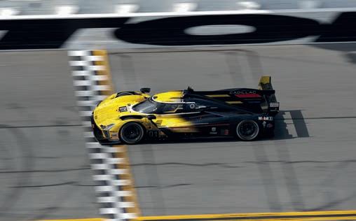
Fig-1 -Example of correlation for a V8 Supercar on a street
And to think all this was generated using only the data provided in Table 1. It did not, as many think, require a $100,000 data logging suite.
Circuit model
As always actual data is coloured and simulated is black. The the second trace is throttle, the third and fourth traces are dampers is steering. The morale of the story is all this was generate provided in Table 1. It did not require a $100 000 data logging
You can also readily create a circuit model from a car fitted with the channels outlined in Table 1. Firstly, the lateral acceleration you can deduce the curvature file, which describes the path the vehicle takes. The methodology for this is given by equation 6
Also you can readily create a circuit model with a car fitted in Table -1. Firstly the lateral accelerationyou can deduce describes the path the vehicle takes. The equation for this is Here we have is the compression of the corner of the car for corner i, is the spring deflection for corneri, and is the wheel movement for corner i. The convention car corners is at the discretion of the user. The convention that I use is 1 is the front, 2 is the right front, 3 is the left rear and is the right rear.
Where,
CLA (sometimes called CZ / CzT) is the lift coefficient CDA (sometimes called Cx / CxT) is the drag coefficient awf is the factor of downforce on the front T(rpm) is the engine torque in Nm gr is the gear ratio (in terms of torque multiplication from engine to gearbox) rt is the rolling radius of the tyre
Where, iR = Curvature (1/m) iR = curvature (1/m) ay = Lateral acceleration (g) ay = lateral acceleration (g)
V = Vehicle Speed (km/h)
V = vehicle Speed (km/h) cv_sign= Sign of corner (+1 for ay being positive -1 for a left hand turn) the user has deduced the corner deflections the ride heights can be calculated. front and rear ride heights rh and rh are given by, and are the initial ride heights. These can be either drop heights or heights from the floor. The choice is really up to the end user and whether they clarify the aeromap by either drop or floor heights.
I have presented on multiple occasions an F3 hand calculation example, and what I have just shown forms the basis of the ChassisSim aero modelling toolbox.
Where, rhf 0 and rhr0 are the initial ride heights. These can be either drop heights or ride heights from the floor. The choice is up to the end user and whether they want to clarify the aeromap by either drop or floor heights.
The other thing you can do with the data in Table 1 is use it to reverse engineer the tyre model of the car. You can do this by doing a bunch of track replays and changing the tyre model to minimise the differences between actual and simulated g. This is the basis of the ChassisSim tyre force modelling toolbox, and the results are shown in Figure 1 cv_sign = sign of corner (+1 for ay being positive for a righthand turn, -1 for a left-hand turn)
This is one of the best kept secrets of data analysis. The roa reverse engineered from the dampers (the ChassisSim bump excellent case in point). Lastly you can reverse engineer the vertical g accelerometer and GPS data. It is actually a spin we just sub az for ay and look at the vertical curvature from by the GPS Altitude. We simply compare this to the normal az and the difference is the road camber. That's how straight that we have clarified the ride heights and forces for this particular point the aerodynamic forces associated with this point is given by,
Now that we have clarified the ride heights and forces for this particular point, the aerodynamic forces associated with this point is given by equation 5
Now this is one of the best kept secrets in data analysis. The road surface profile can be reverse engineered from the dampers (the ChassisSim bump profile modelling is an excellent case in point).
However the real question to answer is what is the price? The exorbitant as you would think.Let me present two options be Motec the other Magneti Marelli. The break down of prices presented in Table -2
As always, actual data is coloured and simulated is black. The first channel is speed, the second trace is throttle, the third and fourth traces are dampers and the fifth trace is steering.
Table -2a-Breakdown of prices fordata logging-Motec
(sometimes referred to as C are the lift and drag coefficients, awf is the fa is the engine torque in m, gr is the gear ratio (in ter multiplication from engine to gearbox) and r presented on multiple occasionsan F3 hand calc example. What I have just presented basis of the ChassisSim aero modelling toolbox.
other thing you can do with the data presented in Table -1 is to use this data to engineer the tyre model of the car. ou can do thisby doing a whole bunch of replays and changing the tyre model to minimise the differences between actual
Lastly, you can reverse engineer the road camber from the vertical g accelerometer and GPS data. It is actually a spin off from equation 6. Here we just sub az for ay and look at the vertical curvature from the road surface provided by the GPS altitude. Then we simply compare this to the normal curvature calculated from az and the difference is the road camber. That’s how straightforward it is. Bearing in mind what I said earlier about king’s ransoms and the cost of the earth, the real question to answer is what is the price of all this? To answer that fairly, let me present two options you can go with.
One is MoTeC, the other Magneti Marelli. The breakdown of prices, in Australian dollars, is presented in Tables 2a and 2b
Table 2a: Breakdown of prices for data logging, option 1 – MoTeC
Item Price
MoTeC ADL 3 $5000
Three-axis accelerometer $1200
Damper pots $400
Steering sensor $200
Throttle sensor $200
Temp sensor $200
Pressure sensor $400
Brake pressure sensor $197.50
GPS package $400
Table 2b: Breakdown of prices for data logging, option 2 – Magneti Marelli
Item Price
But pay this expense once on all your data logging gear and every minute you spend testing on track afterwards instantly becomes more valuable.
Of course, what we have just covered is only the bare bones to get you started with data logging. If you want to take things over the top and have everything you could possibly need, allow me to refer you to Table 3
Over the top
Equip yourself, and your racecar, with all these channels and they will give you everything you need to not just race engineer the car, but to be able to develop it. Let’s break this list down a bit.
Firstly, laser ride heights and the suspension loads complement the damper pots quite nicely. The suspension loads, also known as strains, similarly complement the damper pots nicely, and this combined with the suspension movement will allow you to nail down the tyre spring rates.
Table 3: Extra data channels to take you all the way
Channel RoleFrequency
Pitot speed Chassis50Hz
Suspension load front left Chassis200Hz
Suspension load front right Chassis200Hz
Suspension load rear left Chassis200Hz
Suspension load rear right Chassis200Hz
Front laser ride height Chassis200Hz
Rear laser ride height Chassis200Hz
Internal tyre temperature front left Chassis10Hz
Internal tyre temperature front right Chassis10Hz
Internal tyre temperature rear left
Chassis10Hz rear right Chassis10Hz
Internal tyre temperature
External tyre temperature front left
External tyre temperature front right
Chassis50Hz
Chassis50Hz
External tyre temperature rear left Chassis50Hz
Magneti Marelli
DDU310 dash logger $5350
Three-axis accelerometer $395
Damper pots $450
Steering sensor $225
Throttle sensor $127.50
Temp sensor $65
Pressure sensor $185
Brake pressure sensor $197.50
GPS package $1150
Whichever road you take, the investment is around Aus$10,000, including tax (approx. £5665 / US$6860). Not outrageous for everything you’ll need to effectively engineer a racecar, especially bearing in mind these are also the Rolls-Royce options. There are systems like AIM that can get you going for even less, and I would invite Cosworth Electronics to put in its own costings.
Bottom line
The Confederation of Australian Motorsport (CAMS) is capping the cost of Formula 4 at Aus$170,000 (approx. £96,300 / US$116,675) and a rolling chassis will cost you in the order of Aus$60,000 (approx. £33,990 / US$41,180).
If you still think that sounds a lot, think of it another way. $10,000 would roughly cover a couple of days of testing. Too high? Be honest with yourself here, and factor in flights, accommodation, car transport, sustenance for driver, engineer and two mechanics as well as the cost of running the car. It soon adds up.
I could have added laser ride heights left and right to this already extensive list but you can nail that down with just the two laser ride heights at the front and rear that I have mentioned. However, these sensors do come with a word of warning: do not skimp on these products. Laser ride height sensors and strains are a bit like romantic movies. When they work they are fantastic, when they don’t work they are awful, so choose wisely.
What the tyre temperature sensors do is allow you to fully understand what the tyre on your racecar is doing. Ignoring tyre temperature effects with race tyres is like denying there is a river in Egypt. Foolish, at best. Knowing the internal and surface temperatures reveals what is truly going on with the tyre, and is why I put so much trouble and effort into incorporating this in the ChassisSim tyre model.
Lastly, yaw rate will finish the picture. The reason is because it allows you to determine what is going on with sideways velocity, and nail down the picture of the stability index I have written about on multiple occasions.
Returning to money for a moment, the strains and laser ride heights will set you back about Aus$1000 each, and the tyre temperature monitoring a further Aus$5000. A good yaw rate sensor is about Aus$1000 so, if you tack all that onto the original expenditure of around Aus$10,000, you can go all out for another Aus $13,000.
Pricey, perhaps, but given that a GT3 car is in six-figure territory, what’s an additional few grand?
External tyre temperature rear right
Chassis50Hz
Yaw rate sensor Chassis50Hz
GPS altitude Chassis10Hz
My final two cents on the matter is simply to say you will live and die by the quality of your sensors. If you are a running a club car, or something like a Formula Ford and want to get started, you can use cheaper sensors. But this only buys you time. Once you are at F4 level, or above, do it once and do it right.
Just as a couple of examples, Texense Sensors provide a great range of sensors, from damper pots and steer sensors to accelerometers, and its US branch is very knowledgeable (and not as expensive as you might think). When it comes to tyre sensors, and tyre pressure monitoring systems, bf1 systems are well worth a look.
Conclusion
In summing up, not only is data logging essential, both for understanding and running your car, but also to educate yourself on the essential skills you need as you progress up the motorsport ladder.
You only need a handful of channels to achieve meaningful results, and the correct combination of them will allow you to reverse engineer further parameters on the car, making it a perfect complement to tools such as ChassisSim. The combination of the two will allow you to extract the maximum performance from your racecar.