30 minute read
Personal safety


Warning
Avoid injury! Always do the following before lubricating, maintaining, or servicing the machine.
Advertisement
1. Disengage all drives.
2. Engage parking brake.
3. Lower all attachments to the ground, or raise and engage all safety locks.
4. Shut off engine.
5. Remove key from key switch.
6. Switch off battery key, if installed.
7. Wait for all machine movement to stop.
Failure to comply could result in death or serious injury.
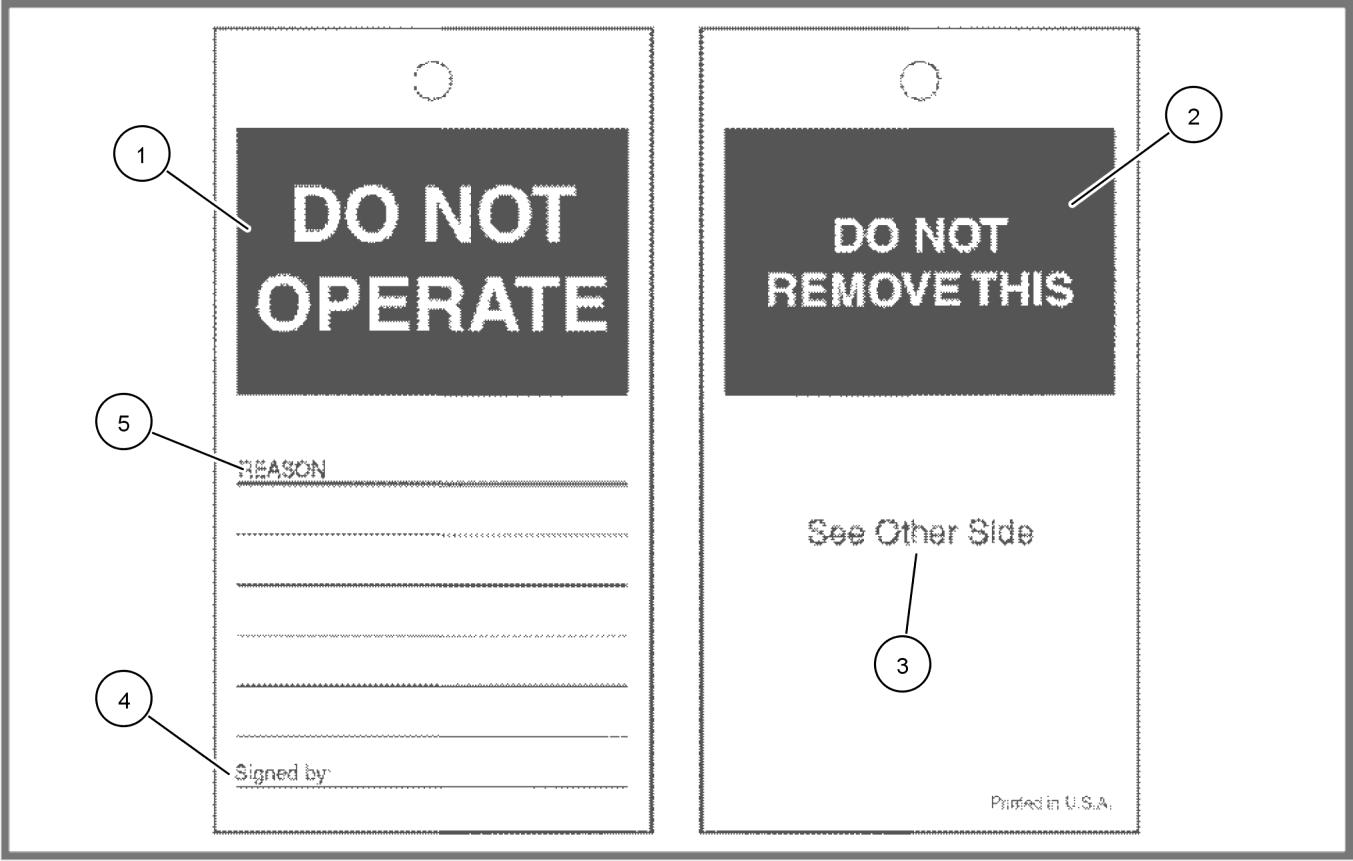
Before you service the machine, put a DO NOT OPERATE tag on the instrument panel.
321_4614 1 DO NOT OPERATE TAG
A. (1) Do not operate.
B. (2) Do not remove this.
C. (3) See other side.
D. (4) Signed by.
E. (5) Reason
The DO NOT OPERATE tag can be obtained from your NEW HOLLAND AGRICULTURE dealer.
Safety rules
Important notice to operators
Your machine may be equipped with special guarding or other devices in compliance with local legislation. Some of the guarding or safety devices require active use by the operator. Check local legislation on the usage of this machine.
Accident prevention
Farm accidents can be prevented with your help.
No accident prevention program can be successful without the wholehearted cooperation of the person who is directly responsible for the operation of the equipment.
To read accident reports from all over the country is to be convinced that a large number of accidents can be prevented only by the operator anticipating the result before the accident is caused and doing something about it.
It is said that "The best kind of safety device is a careful operator who with care and mature consideration can save more lives and limbs than any accident prevention program which is not adhered to".
Further in this chapter you will find a list of the most important safety precautions. Take time to read and follow the instructions and furthermore, be careful!
Some pictures in this manual may show the safety guarding open or removed to better illustrate a particular feature or adjustment.
Ensure to close or replace all guards before operating the machine.
General and operating safety
Most farm machinery accidents can be avoided by the observance of a few simple safety precautions.
1. The machine must only be used by a skilled operator familiar with all the controls and harvesting techniques on cultivated land with slopes up to maximum 26 % ( 15 °) uphill and downhill.
2. Do not permit anyone other than the operator to ride on the machine.
3. Before starting the engine, ensure everyone is clear of the machine.
4. Warn bystanders by sounding the horn several times.
5. Keep children away from and off the machine at all times.
6. No-one should be standing on the ladders when the machine is moving.
7. When driving on public roads, observe traffic regulations, adapt your speed to road and traffic conditions and ensure that all lights and other safety mechanisms on the machine (if they are required) are fitted and work properly. The grain tank must be empty when driving on the road. Ensure that the unloading tube is locked in its closed position.
8. Ensure that both brake pedals are locked together when travelling on public roads.
9. Ensure the hazard warning signs provided are installed at the front and the rear of the machine and use the rotating amber traffic warning beacon(s) (if equipped) when driving on public roads to indicate the vehicle is of abnormal size and is slow-moving.
10. Do not brake abruptly to avoid tipping of the machine.
11. Do not exceed 20 km/h (12.5 mph) when driving downhill. If necessary, change into a lower gear before starting the descent.
12. Never travel at high speed in crowded areas.
13. Avoid making turns at high speed.
14. When driving on public roads, either with the grain header loaded on a trailer and attached to the rear of the machine, or with the grain header still attached to the machine (provided local legislation allows), always be aware and conscious of its size. 84547569
15. Before operating the machine ensure that all safety guards are installed.
16. Check the wheel nuts torque as described in MAINTENANCE.
17. Do not enter the grain tank while the machine engine is running. With engine stopped, use a wooden clearing club should the grain tank unloading auger become bridged. Take utmost care not to be pulled into the grain tank in case un-bridging is required.
18. Do not attempt to clean, lubricate or carry out any adjustments on the machine while it is in motion or while the engine is running.
19. Never leave the operator's platform without first disengaging the machine drive mechanism, lowering the header, stopping the engine, applying the park brake and removing the ignition key.
20. Do not work under the machine header unless it is securely blocked and/or the header safety latch is engaged.
21. Do not work around the machine in loose clothing that might catch in any of the moving parts.
22. Keep hands away from moving parts of the machine.
23. Keep the fire extinguisher within easy reach of the operator. Ensure to replace it by a similar type of extinguisher or have it checked or refilled after every usage and/or date of expiry.
24. Do not step on the grain tank extensions, covers, or the cab roof.
25. Machine dust can cause "farmer's lung" disease. It may also contain harmful spraying residues. Keep the cab door and window closed during operation. Wear a dust mask when cleaning the accumulated dust and debris on the machine.
Hydraulic system safety
• Hydraulic oil leaking under pressure can penetrate the skin and cause infection or other injury. To prevent personal injury:
• Relieve all pressure before disconnecting fluid lines.
• Before applying pressure, make sure all connections are tight and components are in good condition.
• Never use your hand to check for suspected leaks under pressure. Use a piece of cardboard or wood for this purpose.
• If injured by leaking fluid, seek medical attention immediately.
• The hydraulic hoses and fittings on your machine meet engineering specifications for the particular function. When replacing damaged, blown or worn hoses or fittings, use only manufacture authorized service parts.
• Care in hydraulic hose installation is a must:
• Make sure pressure is relieved before starting installation procedure.
• DO NOT kink or twist a hose, failure may occur.
• Properly route the hose.
• Have a certified hydraulic technician install the hose.
• Remove air from the hydraulic system after installing any hydraulic component.
• Periodically check hydraulic system for leaks or damage. check for:
• Leaks at hose fitting or in hose.
• Damaged hoses and/or fittings.
• Kinked, crushed, flattened, hard blistered, heat cracked, charred, twisted, soft or loose covered hoses.
• Corroded or damaged fittings.
• Leaking ports.
• Excessive dirt and debris around hoses and/or fittings.
• Damaged or missing hose retaining clamps, guards, shields, etc.
• DO NOT stand on or use a hose as a step. DO NOT pull or apply external forces to the hose. The hose may fail and cause injury.
• Keep all persons away from the working area. Mechanisms controlled by fluid power can become hazardous if a hose fails. Lifted mechanisms can fall to the ground, machine steering may fail, etc.
84547569 01/12/2011
• Stay clear of a pressurized hose assembly that has blown apart. Hose fittings can be thrown off at high speed and a loose hose can whip around with great force.
• Hydraulic fluid can reach high temperatures. Allow fluid to cool before servicing the system.
• Escaping fluid under pressure may form a mist or fine spray which can flash or explode upon contact with an ignition source.
• Vibration can reduce hose service life. Make sure all retaining clamps and/or devices are secured.
• Environmental conditions can cause hose and fittings to deteriorate. Inspect hydraulic hoses periodically. Replace worn or damaged hoses and fittings.
Safety requirements for fluid power systems and components - Hydraulics (European standard PR EN 982)
Flexible hose assemblies must not be constructed from hoses which have been previously used as part of a hose assembly.
Do not weld hydraulic piping.
When flexible hoses or piping are damaged, replace them immediately.
It is forbidden to modify a hydraulic accumulator by machining, welding or any other means.
Before removing hydraulic accumulators for servicing, the liquid pressure in the accumulator must be reduced to zero.
Pressure check on hydraulic accumulators shall be carried out by method recommended by the accumulator manufacturer.
Care must be taken not to exceed the maximum allowable pressure of the accumulator. After any check of adjustment there must be no leakage of gas.
Danger of death by electrocution!
Pay special attention to the overhead power lines. Make sure the machine has sufficient clearance to pass in all directions (also with raised or opened machine components). Also think of the radio aerial(s) or any other factoryfitted accessory or parts which may have been added afterwards.
Should a contact between the machine and an electric power line occur, then the following precautions must be taken: Stop the machine movement immediately, stop the engine and apply the hand-brake or parking brake.
Check if you can safely leave the cab or your actual position without direct contact with electric wires. If not, stay in your position and call for help. If you can leave your position without touching the lines, jump off the last step or support position to ensure that there is no contact between any part of your body and the ground at any time. Do not touch the machine afterwards until power to the lines has been shut off. When people approach the machine, warn them not to touch the machine but to ask the electric power supply company to shut off the power to the lines.
Engine safety
1. Keep the engine area clean of dust, chaff and straw to prevent the possibility of fires.
2. Never idle the engine in an enclosed area as harmful exhaust gases may build up.
3. Wear a suitable hearing protective device, such as ear muffs or ear plugs, if you are exposed to noise which you feel is uncomfortable.
4. The cooling system operates under pressure which is controlled by the radiator cap. It is dangerous to remove the cap while the engine is hot.
5. Switch off the engine and wait until it has cooled. Even then use extreme care when removing the cap. Cover the cap with a rag and turn it slowly to the first stop to allow the pressure to escape before removing the cap completely. Stand clear of the radiator opening as hot coolant may splash out.
6. Never add cold water to a hot radiator. Failure to follow these instructions may result in serious personal injury from hot coolant or steam blowout and/or damage to the cooling system or engine.
7. Antifreeze contains monoethylene glycol and other chemicals which are toxic if taken internally and can be absorbed in toxic amounts through repeated or prolonged skin contact. Follow these precautions when working with antifreeze:
8. Do not take antifreeze internally. If antifreeze is swallowed accidentally, obtain medical attention immediately.
9. Keep antifreeze in sealed containers out of reach of children, livestock or pets.
10. Periodically check the engine coolant and heater hoses for signs of wear, deterioration, weak sections and leaks to avoid hazardous situations and possible injury caused by hot coolant.
11. The fuel oil in the injection system is under high pressure and can penetrate the skin. Unqualified persons should not remove or attempt to adjust a fuel injection pump, injector, nozzle or any other part of the fuel injection system. Failure to follow these instructions may result in serious injury. If fuel is injected through the skin, medical assistance should be obtained.
12. Be very careful to avoid contact with hot engine oil. If the engine oil is extremely hot, allow the oil to cool to a moderately warm temperature for safe removal.
13. Do not handle a hot oil filter with bare hands.
14. Continuous and prolonged contact with used engine oil may cause skin cancer. Protect your skin by wearing heavy plastic gloves. If oil gets onto the skin, wash promptly with soap and water.
Diesel fuel safety
1. Under no circumstances should gasoline, alcohol or blended fuels be added to diesel fuel. These combinations can create an increased fire or explosive hazard. In a closed container, such as a fuel tank, such blends are more explosive than pure gasoline. Do not use these blends.
2. Never remove the fuel tank cap or refuel with the engine running or hot. Refuel the machine only when the engine has been turned off. Do not smoke or use a naked flame when refuelling or when standing near fuel tanks.
3. Maintain control of the fuel filler pipe nozzle when filling the tank.
4. Do not fill the fuel tank to capacity. Allow room for expansion.
5. Wipe up spilled fuel immediately.
6. Always tighten the fuel tank cap securely.
7. If the original fuel tank cap is lost, replace it with an NEW HOLLAND AGRICULTURE cap. A non-approved, proprietary cap may not be safe.
8. Keep equipment clean and properly maintained.
9. Do not drive equipment near open fires.
10. Never use fuel for cleaning purposes.
Battery safety
WARNING
Explosion hazard!
Batteries emit explosive gases. Always ventilate when using in an enclosed area or when charging. Keep the battery away from sparks, open flames, and other ignition sources. Failure to comply could result in death or serious injury.
WARNING
W0369A
Battery acid causes burns. Batteries contain sulfuric acid. Battery electrolyte contains sulfuric acid. Contact with skin and eyes could result in severe irritation and burns. Always wear splash-proof goggles and protective clothing (gloves and aprons). Wash hands after handling.
Failure to comply could result in death or serious injury.
The essential precautions listed below must be observed:
• Do not use an open flame to check the electrolyte level. Keep sparks, flames and lighted tobacco away.
84547569 01/12/2011
• Do not produce sparks with cable clamps when charging the battery or starting the engine with a slave battery.
• Wear eye protection when working near batteries.
• Wear eye protection and gloves if removing the battery cover plugs.
• Provide ventilation when charging or using in an enclosed space.
• Ensure the vent plugs are correctly installed and tight.
If the electrolyte comes into contact with the skin, eyes or is taken internally, treat as follows:
• Skin: Flush with cold water.
• Eyes: Flush with cold water for 10 minutes and get prompt medical attention.
• Internal: Call a doctor immediately.
Fire and explosion prevention
• Due to the flammable nature of the crop materials encountered, fire risks are high. This risk can be minimized by frequent removal of accumulated crop material from the machine and checking for overheated machine components. If oil leaks appear, re-torque bolts or replace gaskets as necessary.
• Remove all trash or debris from the machine each day. Especially check the engine area and exhaust system.
• Sparks or flame can cause the hydrogen gas in a battery to explode. To prevent an explosion do the following:
• When disconnecting the battery cables, disconnect the negative (▬) cable first; when connecting the battery cables, connect the negative (▬) cable last.
• When connecting jumper cables to start the engine, use the procedure shown in this manual (see Auxiliary Battery connections in this manual).
• Do not short circuit the battery posts with metal items.
• Do not weld, grind or smoke near a battery.
• Sparks from the electrical system or engine exhaust can cause an explosion and fire. Before you operate this machine in an area with flammable dust or vapors, use good ventilation to remove the flammable dust or vapors.
• Use nonflammable cleaning solvent to clean parts.
• A fire can cause death or injury. Always have fire extinguisher near or on the machine. Make sure the fire extinguishers are serviced according to the manufacturers instructions.
• If a fire extinguisher has been used, always recharge or replace the fire extinguisher before operating the machine.
• Keep the cooling system clean and maintain the correct coolant level.
• Make sure that you DO NOT store oily rags or other flammable materials on the machine.
• Engine fuel can cause an explosion or fire. Do not fill the fuel tank with the engine running; if you are near an open fire; or if you are welding, smoking, etc.
• If the machine has an oil, fuel or hydraulic leak, always repair the leak and clean the area before operating.
• Check the electrical system for loose connections or frayed insulation. Repair or replace the loose or damaged parts.
• Before welding or using a torch on the machine, clean the area to be repaired.
Wheels and tires
The life and performance of the tires depends largely upon maintaining the correct pressure. Keep the tires inflated to the pressures given in SPECIFICATIONS.
Check the wheel nuts torque daily during the first week of operation and thereafter on a weekly basis.
The wheel nut torque is given in SPECIFICATIONS.
Whenever preparing to jack-up the machine, park on a level, firm surface and securely block the drive tire opposite the side to be lifted, both in front and rear.
84547569 01/12/2011
Basic instructions - Important notice regarding equipment servicing
All repair and maintenance work listed in this manual must be carried out only by qualified dealership personnel, strictly complying with the instructions given, and using, whenever possible, the special tools.
Anyone who performs repair and maintenance operations without complying with the procedures provided herein shall be responsible for any subsequent damages.
The manufacturer and all the organizations of its distribution chain, including - without limitation - national, regional, or local dealers, reject any responsibility for damages caused by parts and/or components not approved by the manufacturer, including those used for the servicing or repair of the product manufactured or marketed by the manufacturer. In any case, no warranty is given or attributed on the product manufactured or marketed by the manufacturer in case of damages caused by parts and/or components not approved by the manufacturer.
The information in this manual is up-to-date at the date of the publication. It is the policy of the manufacturer for continuous improvement. Some information could not be updated due to modifications of a technical or commercial type, or changes to the laws and regulations of different countries.
In case of questions, refer to your NEW HOLLAND AGRICULTURE Sales and Service Networks.
Torque - Minimum tightening torques for normal assembly
NOTE: M4 through M8 hardware torque specifications are shown in pound-inches. M10 through M24 hardware torque specifications are shown in pound-feet.
Metric Flanged Hardware
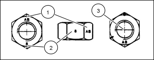
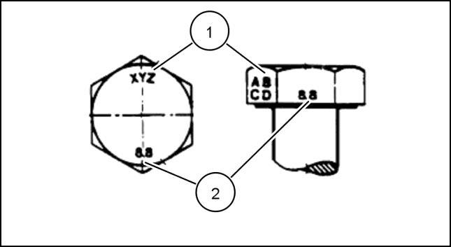
1. Manufacturer's Identification
2. Property Class
3. Clock Marking of Property Class and Manufacturer's Identification
° apart indicate Class 10 properties, and marks 120 ° apart indicate Class 8.
INCH NON-FLANGED HARDWARE
marks in through 1 in hardware torque specifications are shown in pound-feet.
NOTE: For Imperial Units, 1/4 in and 5/16 in hardware torque specifications are shown in pound-inches.
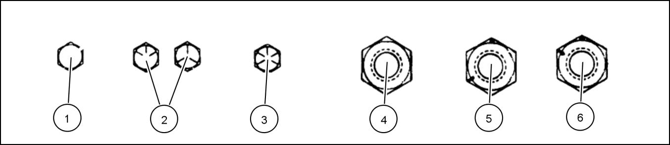
Inch Lock Nuts, All Metal (Three optional methods)
Torque - Standard torque data for hydraulics
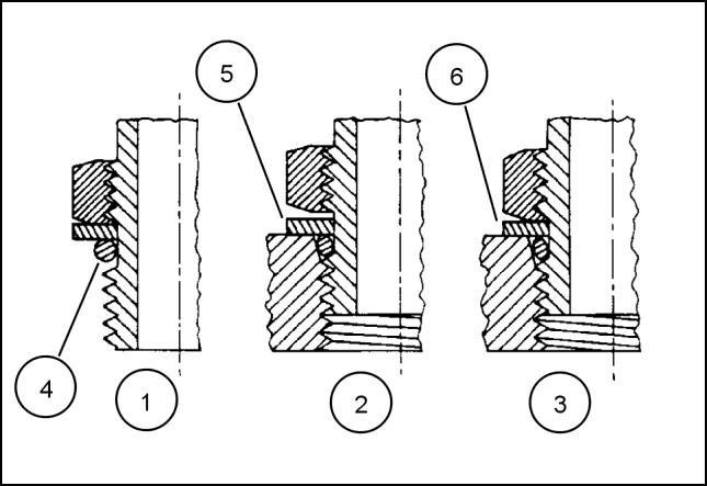
INSTALLATION OF ADJUSTABLE FITTINGS IN STRAIGHT THREAD O RING BOSSES
1. Lubricate the O-ring by coating it with a light oil or petroleum. Install the O-ring in the groove adjacent to the metal backup washer which is assembled at the extreme end of the groove (4).
2. Install the fitting into the SAE straight thread boss until the metal backup washer contacts the face of the boss (5)
NOTE: Do not over tighten and distort the metal backup washer.
3. Position the fitting by turning out (counterclockwise) up to a maximum of one turn. Holding the pad of the fitting with a wrench, tighten the locknut and washer against the face of the boss (6)
STANDARD TORQUE DATA FOR HYDRAULIC TUBES AND FITTINGS
37°
These torques are not recommended for tubes of 12.7 mm (1/2 in) OD and larger with wall thickness of 0.889 mm (0.035 in) or less. The torque is specified for 0.889 mm (0.035 in) wall tubes on each application individually.
Before installing and torquing 37 ° flared fittings, clean the face of the flare and threads with a clean solvent or Loctite cleaner and apply hydraulic sealant LOCTITE® 569 to the 37 ° flare and the threads. Install fitting and torque to specified torque, loosen fitting and retorque to specifications.
Pipe Thread Fitting Torque
Before installing and tightening pipe fittings, clean the threads with a clean solvent or Loctite cleaner and apply sealant LOCTITE® 567 PST PIPE SEALANT for all fittings including stainless steel or LOCTITE® 565 PST for most metal fittings. For high filtration/zero contamination systems use LOCTITE® 545
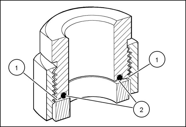
INSTALLATION OF ORFS (O-RING FLAT FACED) FITTINGS
When installing ORFS fittings thoroughly clean both flat surfaces of the fittings (1) and lubricate the O-ring (2) with light oil. Make sure both surfaces are aligned properly. Torque the fitting to specified torque listed throughout the repair manual.
NOTICE: If the fitting surfaces are not properly cleaned, the O-ring will not seal properly. If the fitting surfaces are not properly aligned, the fittings may be damaged and will not seal properly.
NOTICE: Always use genuine factory replacement oils and filters to ensure proper lubrication and filtration of engine and hydraulic system oils.
The use of proper oils, grease, and keeping the hydraulic system clean will extend machine and component life.
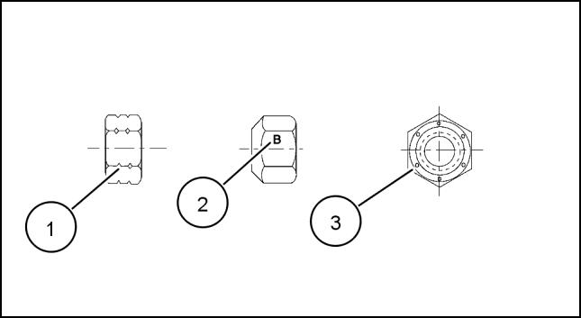
Basic instructions - Chain Wear Tables - Roller Chains
Chain wear
The individual joints in a roller chain articulate as they enter and leave the sprockets. This articulation results in wear on the pins and bushings. Material that is worn away from these surfaces will cause the chain to gradually elongate. Chains do not stretch. Material is worn from pin and bushing.
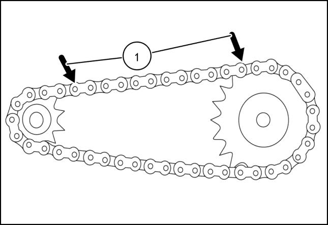
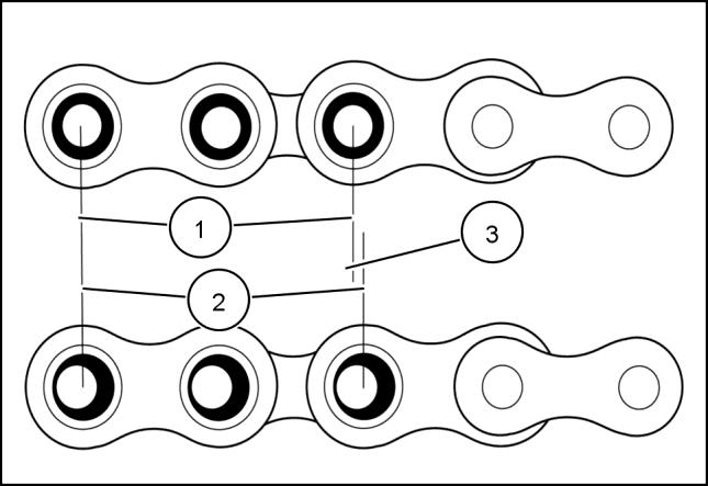
Critical dimensions of the chain are as follows:
• (1) 2X pitch
• (2) Wear plus 2X pitch
• (3) Elongation due to pin and bushing wear
Elongation is normal and may be minimized by proper lubrication and drive maintenance. The rate of wear is dependent upon: the relationship between the load and the amount of bearing area between pin and bushing, the material and surface condition of the bearing surfaces, the adequacy of lubrication, and the frequency and degree of articulation between pins and bushings. The latter is determined by the quantity of sprockets in the drive, their speeds, the number of teeth and the length of the chain in pitches.
An accurate wear measurement (1) can be made by using the above illustration. Measure as closely as possible from the center of one pin to the center of another. The more pitches (pins) contained within the measurement increase the accuracy. If the measured value exceeds the nominal by more than the allowable percentage the chain should be replaced. The maximum allowable wear elongation is approximately 3 % for most industrial applications, based upon sprocket design. The allowable chain wear in percent can be calculated using the relationship: 200/ (N), where (N) is the number of teeth in the large sprocket. This relationship is often useful since the normal maximum allowable chain wear elongation of 3 % is valid only up to 67 teeth in the large sprocket. In drives having fixed center distances, chains running in parallel or where smoother operation is required, wear should be
96091469 2 limited to approximately 1.5 %
For example, if 12 pitches (12 pins) of a #80 chain were measured and the result was 313.944 mm (12.360 in) or greater (using 3 % as the maximum allowable wear), the chain should be replaced. Anything less than 313.944 mm (12.360 in) would still be acceptable by most industrial standards.
Basic instructions - Shop and Assembly
Shimming
For each adjustment operation, select adjusting shims and measure individually using a micrometer, then add up the recorded values. Do not rely on measuring the entire shimming set, which may be incorrect, or the rated value indicated on each shim.
Rotating Shaft Seals
For correct rotating shaft seal installation, proceed as follows:
• before assembly, allow the seal to soak in the oil it will be sealing for at least thirty minutes.
• thoroughly clean the shaft and check that the working surface on the shaft is not damaged.
• position the sealing lip facing the fluid; with hydrodynamic lips, take into consideration the shaft rotation direction and position the grooves so that they will deviate the fluid towards the inner side of the seal.
• coat the sealing lip with a thin layer of lubricant (use oil rather than grease) and fill the gap between the sealing lip and the dust lip on double lip seals with grease.
• insert the seal in its seat and press down using a flat punch or seal installation tool. Do not tap the seal with a hammer or mallet.
• whilst inserting the seal, check that it is perpendicular to the seat; once settled, make sure that it makes contact with the thrust element, if required.
• to prevent damaging the seal lip on the shaft, position a protective guard during installation operations.
O-RING SEALS
Lubricate the O-RING seals before inserting them in the seats, this will prevent them from overturning and twisting, which would jeopardise sealing efficiency.
Sealing Compounds
Apply one of the following sealing compounds on the mating surfaces when specified: SILMATE® RTV1473, or LOCTITE® RTV 598 or LOCTITE® INSTANT GASKET 587 BLUE. Before applying the sealing compound, prepare the surfaces as directed on product container or as follows:
• remove any incrustations using a metal brush.
• thoroughly de-grease the surfaces using a locally approved cleaning agent such as safety solvent or brake parts cleaner.
Spare Parts
Only use "CNH Original Parts" or " NEW HOLLAND AGRICULTURE Parts".
Only genuine spare parts guarantee the same quality, duration and safety as original parts, as they are the same parts that are assembled during standard production. Only "CNH Original Parts" or " NEW HOLLAND AGRICULTURE Parts" can offer this guarantee.
When ordering spare parts, always provide the following information:
• machine model (commercial name) and serial number
• part number of the ordered part, which can be found in the "Microfiches" or the "Service Parts Catalogue", used for order processing
84547569 01/12/2011
PROTECTING THE ELECTRONIC/ ELECTRICAL SYSTEMS DURING CHARGING OR WELDING
To avoid damage to the electronic/electrical systems, always observe the following:
1. Never make or break any of the charging circuit connections, including the battery connections, when the engine is running.
2. Never short any of the charging components to ground.
3. Always disconnect the ground cable from the battery before arc welding on the combine or on any header attached to the combine.
• position the welder ground clamp as close to the welding area as possible
• if welding in close proximity to a computer module, then the module should be removed from the combine
• never allow welding cables to lay on, near or across any electrical wiring or electronic component while welding is in progress
4. Always disconnect the negative cable from the battery when charging the battery in the combine with a battery charger.
NOTICE: If welding must be performed on the unit, either the combine or the header (if it is attached), the battery ground cable must be disconnected from the combine battery. The electronic monitoring system and charging system will be damaged if this is not done.
Remove the battery ground cable. Reconnect the cable when welding is completed.
Warning
Battery acid causes severe burns. Batteries contain sulfuric acid. Avoid contact with skin, eyes or clothing. Antidote - EXTERNAL: flush with water. INTERNAL: drink large quantities of water or milk. Follow with milk of magnesia, beaten egg or vegetables oil. Call physician immediately. EYES: flush with water for 15 minutes and get prompt medical attention.
Tools
The tools that NEW HOLLAND AGRICULTURE suggests and illustrate in this manual have been:
• specifically researched and designed for use with NEW HOLLAND AGRICULTURE machines
• essential for reliable repair operations
• accurately built and rigorously tested so as to offer efficient and long-lasting operation
By using these tools, repair personnel will benefit from:
• operating in optimal technical conditions
• obtaining the best results
• saving time and effort
• working in safe conditions
NOTE: The terms "front", "rear", "right-hand" and "left-hand" (when referred to different parts) are determined from the rear, facing in the direction of travel of the machine during operation.
Basic instructions - How To Use and Navigate Through This Manual
Technical Information
This manual has been produced by a new technical information system. This new system is designed to deliver technical information electronically through Web delivery, DVD and in paper manuals. A coding system called SAP has been developed to link the technical information to other Product Support functions, e.g., Warranty.
Technical information is written to support the maintenance and service of the functions or systems on a customer's machine. When a customer has a concern on his machine it is usually because a function or system on his machine is not working at all, is not working efficiently, or is not responding correctly to his commands. When you refer to the technical information in this manual to resolve that customer's concern, you will find all the information classified using the SAP coding, according to the functions or systems on that machine. Once you have located the technical information for that function or system then you will find all the mechanical, electrical or hydraulic devices, components, assemblies and sub assemblies for that function or system. You will also find all the types of information that have been written for that function or system, the technical data (specifications), the functional data (how it works), the diagnostic data (fault codes and troubleshooting) and the service data (remove, install adjust, etc.).
By integrating SAP coding into technical information , you will be able to search and retrieve just the right piece of technical information you need to resolve that customer's concern on his machine. This is made possible by attaching 3 categories to each piece of technical information during the authoring process.
The first category is the Location, the second category is the Information Type and the third category is the Product:
• LOCATION - is the component or function on the machine, that the piece of technical information is going to describe e.g. Fuel tank.
• INFORMATION TYPE - is the piece of technical information that has been written for a particular component or function on the machine e.g. Capacity would be a type of Technical Data that would describe the amount of fuel held by the Fuel tank.
• PRODUCT - is the model for which the piece of technical information is written.
Every piece of technical information will have those 3 categories attached to it. You will be able to use any combination of those categories to find the right piece of technical information you need to resolve that customer's concern on his machine.
That information could be:
• the description of how to remove the cylinder head
• a table of specifications for a hydraulic pump
• a fault code
• a troubleshooting table
• a special tool
How to Use this Manual
This manual is divided into Sections. Each Section is then divided into Chapters. Contents pages are included at the beginning of the manual, then inside every Section and inside every Chapter. An alphabetical Index is included at the end of a Chapter. Page number references are included for every piece of technical information listed in the Chapter Contents or Chapter Index.
Each Chapter is divided into four Information types:
• Technical Data (specifications) for all the mechanical, electrical or hydraulic devices, components and, assemblies.
• Functional Data (how it works) for all the mechanical, electrical or hydraulic devices, components and assemblies.
• Diagnostic Data (fault codes, electrical and hydraulic troubleshooting) for all the mechanical, electrical or hydraulic devices, components and assemblies.
• Service Data (remove disassembly, assemble, install) for all the mechanical, electrical or hydraulic devices, components and assemblies.
Sections
Sections are grouped according to the main functions or a systems on the machine. Each Section is identified by a letter A, B, C etc. The amount of Sections included in the manual will depend on the type and function of the machine that the manual is written for. Each Section has a Contents page listed in alphabetic/numeric order. This table illustrates which Sections could be included in a manual for a particular product.
SECTION
A - Hydraulic – Pneumatic – Electrical – Electronic Systems
B - Engine and PTO In
C - Transmission, Drive and PTO Out
D - Axles, Brakes and Steering
E - Frame and Cab
F - Frame Positioning
G - Tool Positioning
H - Hitch and Working Tool
J - Excavating and Landscaping
K - Crop Processing
L - Field Processing
Section Contents
Section Letter Description
HYDRAULIC –PNEUMATIC –ELECTRICAL –ELECTRONIC SYSTEMS
A
This Section covers the main systems that interact with most of the functions of the product. It includes the central parts of the hydraulic, electrical, electronic, pneumatic, lighting and grease lubrication systems. The components that are dedicated to a specific function are listed in the Chapter where all the technical information for that function is included.
ENGINE AND PTO IN B
This Section covers all the functions related to the production of power to move the machine and to drive various devices. In the case of a pulled-type machine, this Section covers the power take-off function where power is provided from the towing machine.
TRANSMISSION, DRIVE AND PTO OUT C
AXLES, BRAKES AND STEERING D
FRAME AND CAB E
This Section covers all the functions related to the transmission of power from the engine to the axles and to internal or external devices. This Section also covers the power take-off function where power is provided to the pull-type machine and additional Process Drive functions.
This Section covers all the functions related to moving the machine, including tracks, wheels, steering and braking. It covers all the axles; both driven axles and non-driven axles, including any axle suspension.
This Section covers all the main functions and systems related to the structure and the body of the machine, including the frame, the shields, the operators cab and the platform. The functions related to the positioning of the machine frame are included in Section F, Frame Positioning.
FRAME POSITIONING F
TOOL POSITIONING G
HITCH AND WORKING TOOL H
This Section covers all the main functions and systems related to positioning of the machine frame or to positioning the attachment on the supporting machine frame.
This Section covers all the functions related to the final and/or automatic positioning of the tool once the tool is positioned using the Working Arm or the machine frame.
This Section covers all the functions related to the articulated or single arms mounted on the front or rear of the machine. A working arm can have various tools and quick couplers mounted on to it. The tools and quick couplers are included in Section J, Excavating and Landscaping.
EXCAVATING AND LANSCAPING J
This Section covers all the functions related to the specific tools that mount on the front, rear or beside the machine. The tools described here can be mounted with the positioning systems (lifting, side shift, swing) listed in Section G Tool Positioning. This Section covers all the quick coupling systems, located between the tool and the positioning system. The tools used for field preparation, soil preparation and treatment, planting and seeding are included.
CROP PROCESSING K
FIELD PROCESSING L
This Section covers all the functions related to crop processing. Examples of crop processing include threshing, baling, windrowing, cutting and conditioning.
This Section covers all the field processing functions of the machine. Examples of field process include seeding, fertilizer application, seedbed preparation and chemical application.
Introduction
This manual contains these Sections:
Contents
INTRODUCTION
HYDRAULIC – PNEUMATIC – ELECTRICAL – ELECTRONIC SYSTEMS A
Chapters
Each Chapter is identified by a letter and number combination e.g. Engine B.10.A The first letter is identical to the Section letter i.e. Chapter B.10 is inside Section B, Engine and PTO In.
CONTENTS
The Chapter Contents lists all the technical data (specifications), functional data (how it works), service data (remove, install adjust, etc..) and diagnostic data (fault codes and troubleshooting) that have been written in that Chapter for that function or system on the machine.
Contents
TECHNICAL DATA
ENGINE AND PTO IN ENGINE _ 10.A
ENGINE - General specification (B.10.A)
FUNCTIONAL DATA
ENGINE - Dynamic description (B.10.A)
SERVICE ENGINE - Remove (B.10.A)
DIAGNOSTIC ENGINE - Troubleshooting (B.10.A)
INDEX
The Chapter Index lists in alphabetical order all the types of information (called Information Units) that have been written in that Chapter for that function or system on the machine.
Index
ENGINE - Dynamic description (B.10.A)
ENGINE - General specification (B.10.A)
ENGINE - Remove (B.10.A)
ENGINE AND PTO IN - B ENGINE
ENGINE - Troubleshooting (B.10.A) 84547569
Information Units and Information Search
Each chapter is composed of information units. Each information unit has the SAP code shown in parentheses which indicates the function and the type of information written in that information unit. Each information unit has a page reference within that Chapter. The information units provide a quick and easy way to find just the right piece of technical information you are looking for.
Example information unit
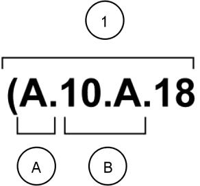
Stack valve - Sectional View (A.10.A.18)
Information Unit SAP code A 10.A
SAP code classification
Primary hydraulic power
CRIL03J033E01A 1
Navigate to the correct information unit you are searching for by identifying the function and information type from the SAP code.
• (1) Function and (2) Information type.
• (A) corresponds to the sections of the repair manual.
(B) corresponds to the chapters of the repair manual.
(C) corresponds to the type of information listed in the chapter contents, Technical Data, Functional Data, Diagnostic or Service.
(A) and (B) are also shown in the page numbering on the page footer. THE REST OF THE CODING IS NOT LISTED IN ALPHANUMERIC ORDER IN THIS MANUAL.
• You will find a table of contents at the beginning and end of each section and chapter. You will find an alphabetical index at the end of each chapter.
• By referring to (A), (B) and (C) of the coding, you can follow the contents or index (page numbers) and quickly find the information you are looking for.
Page Header and Footer
The page header will contain the following references:
• Section and Chapter description
The page footer will contain the following references:
• Publication number for that Manual, Section or Chapter.
• Version reference for that publication.
• Publication date
• Section, chapter and page reference e.g. A.10.A / 9
84547569 01/12/2011
General specification - Biodiesel Fuels
Fatty Acid Methyl Ester Biodiesel (Biodiesel Fuel) consists of a family of fuels derived from vegetable oils treated with methyl esters.
NOTICE: Biodiesel Fuel blends are approved for your engine only if they comply with EN14214 Specification Standards or ASTM D6751.
NOTICE: It is imperative that you check which blend is approved for your engine with your NEW HOLLAND AGRICULTURE dealer. Be aware that the use of Biodiesel Fuel that does not comply with the Standards mentioned above could lead to severe damage to the engine and fuel system of your machine. The use of fuels that are not approved may void NEW HOLLAND AGRICULTURE Warranty coverage.
Biodiesel Fuel Usage Conditions
NOTICE: The Biodiesel Fuel must meet the fuel Specification mentioned above.
Biodiesel Fuel must be purchased from a trusted supplier that understands the product and maintains good fuel quality. Biodiesel Fuel must be pre-blended by the supplier. Mixing Biodiesel Fuels on-site can result incorrect mixture that can lead to problems with both engine and fuel system.
Engine performance is affected by the use of Biodiesel Fuel. There may be up to 12 % reduction in power or torque depending on the blend used.
NOTICE: DO NOT modify the engine and/or injection pump settings to recover the reduced performance.
The reduced power must be accepted if using any Biodiesel Fuel blend.
Some modification may be required to allow your engine to run Biodiesel Fuel. Consult you dealer for complete information on these modifications.
Biodiesel Fuel has a higher cloud point than Diesel Fuel.
NOTICE: The use of high Biodiesel Fuel blends are not recommended in cold weather conditions.
With Biodiesel Fuels, it may be necessary to change the engine oil, engine oil filter and fuel filter elements more frequently than with Diesel Fuels. Biodiesel Fuel can remove rust and particles from the inside of on-site fuel storage tanks that would normally adhere to the sides of the tank. Like particle deposits that commonly occur with Diesel Fuel, these particles can become trapped by the machine fuel filters, causing blockage and shortening filter life. In cold weather, this is more likely to happen. Consult your NEW HOLLAND AGRICULTURE dealer for information on cold weather operation and proper maintenance intervals when using any Biodiesel Fuel blend.
When handling Biodiesel Fuel, care must be taken not to allow water into the fuel supply. Biodiesel Fuel will actually attract moisture from the atmosphere.
Fuel tanks must be kept as full as possible to limit the amount of air and water vapors in them. It may be necessary to drain the fuel filter water tap more frequently.
Potential oxidation and stability could be a problem with the fuel stored in the machine.
NOTICE: Machines must not be stored for more than three months with Biodiesel Fuel blends in the fuel system. If long storage periods are necessary, the engine must run on Diesel Fuel for 20 hours to flush the Biodiesel Fuel out of the engine fuel system prior to storage.
NOTICE: Biodiesel Fuel must not be stored in on-site storage tanks for more than three months.
Any spillage of Biodiesel Fuel must be cleaned up immediately before it can cause damage to the environment and the paint finish of the machine.
Before using Biodiesel Fuel blends you should consult with your dealer to receive full information about the approved blend for your machine and any detailed conditions of its usage.
NOTICE: Be aware that not fulfilling the requirements and conditions of Biodiesel Fuel usage will void your machine’s NEW HOLLAND AGRICULTURE Warranty coverage.
General specification - General Welding
Warning
Explosion hazard!
Batteries emit explosive gases. Always ventilate when using in an enclosed area or when charging. Keep the battery away from sparks, open flames, and other ignition sources. Failure to comply could result in death or serious injury. W0369A
Use a 7013 or 7011 welding rod or wire that meets the following American Welding Society (AWS) specifications: ER80S-D2, ER70S-6 or E70C-M6-H4.
NOTICE: ALWAYS disconnect the battery (both terminals) before welding on any part of the machine. Failure to do so may cause damage to sensitive electrical components.
NOTICE: Locate the welding ground as close as possible to the area to be welded. Do not allow the ground current to pass through any roller type bearing. Arcing inside the roller bearing can result in severe machine damage.