11 minute read
Prepare for Emergencies


First Aid Kit
Be prepared if a fire starts. Keep a first aid kit and fire extinguisher handy. Keep emergency numbers for doctors, ambulance service, hospital, and fire department near your telephone.
Advertisement
Park Machine Safely
Remove the Key
Before working on the machine: Lower all equipment to the ground. Stop the engine and remove the key. Disconnect the battery ground strap. Hang a "DO NOT OPERATE" tag in operator station.

Support Machine Properly
Support Properly
Always lower the attachment or implement to the ground before you work on the machine. If the work requires that the machine or attachment be lifted, provide secure support for them. If left in a raised position, hydraulically supported devices can settle or leak down.
Do not support the machine on cinder blocks, hollow tiles, or props that may crumble under continuous load. Do not work under a machine that is supported solely by a jack. Follow recommended procedures in this manual.
When implements or attachments are used with a machine, always follow safety precautions listed in the implement or attachment operator′s manual.
Protective Clothing
Wear close fitting clothing and safety equipment appropriate to the job. Prolonged exposure to loud noise can cause impairment or loss of hearing. Wear a suitable hearing protective device such as earmuffs or earplugs to protect against objectionable or uncomfortable loud noises.

Operating equipment safely requires the full attention of the operator. Do not wear radio or music headphones while operating machine.

Work in Clean Area
Clean Work Area
Before starting a job: Clean work area and machine. Make sure you have all necessary tools to do your job. Have the right parts on hand.
Service Machines Safely
Moving Parts
Tie long hair behind your head. Do not wear a necktie, scarf, loose clothing, or necklace when you work near machine tools or moving parts. If these items were to get caught, severe injury could result. Remove rings and other jewelry to prevent electrical shorts and entanglement in moving parts.


Work In Ventilated Area
Engine exhaust fumes
Engine exhaust fumes can cause sickness or death. If it is necessary to run an engine in an enclosed area, remove the exhaust fumes from the area with an exhaust pipe extension. If you do not have an exhaust pipe extension, open the doors and get outside air into the area.
Illuminate Work Area Safely
Work Area Safely
Illuminate your work area adequately but safely. Use a portable safety light for working inside or under the machine. Make sure the bulb is enclosed by a wire cage. The hot filament of an accidentally broken bulb can ignite spilled fuel or oil.
Replace Safety Signs
Safety Signs
Replace missing or damaged safety signs. See the machine operator’s manual for correct safety sign placement.

Use Proper Lifting Equipment
Proper Lifting Equipment
Lifting heavy components incorrectly can cause severe injury or machine damage. Follow recommended procedure for removal and installation of components in the manual.


Explosive Tire and Rim Parts
Explosive separation of a tire and rim parts can cause serious injury or death.
Do not attempt to mount a tire unless you have the proper equipment and experience to perform the job.

Always maintain the correct tire pressure. Do not inflate the tires above the recommended pressure. Never weld or heat a wheel and tire assembly. The heat can cause an increase in air pressure resulting in a tire explosion. Welding can structurally weaken or deform the wheel.
When inflating tires, use a clip-on chuck and extension hose long enough to allow you to stand to one side and NOT in front of or over the tire assembly. Use a safety cage if available. Check wheels for low pressure, cuts, bubbles, damaged rims or missing lug bolts and nuts.
Decommissioning — Proper Recycling and Disposal of Fluids and Components
Recycle Waste
Safety and environmental stewardship measures must be taken into account when decommissioning a machine and/or component. These measures include the following:
Use appropriate tools and personal protective equipment such as clothing, gloves, face shields or glasses, during the removal or handling of objects and materials. Follow instructions for specialized components.
Release stored energy by lowering suspended machine elements, relaxing springs, disconnecting the battery or other electrical power, and releasing pressure in hydraulic components, accumulators, and other similar systems.
Minimize exposure to components which may have residue from agricultural chemicals, such as fertilizers and pesticides. Handle and dispose of these components appropriately.
Carefully drain engines, fuel tanks, radiators, hydraulic cylinders, reservoirs, and lines before recycling components. Use leak-proof containers when draining fluids. Do not use food or beverage containers. Do not pour waste fluids onto the ground, down a drain, or into any water source.
Observe all national, state, and local laws, regulations, or ordinances governing the handling or disposal of waste fluids (example: oil, fuel, coolant, brake fluid); filters; batteries; and, other substances or parts. Burning of flammable fluids or components in other than specially designed incinerators may be prohibited by law and could result in exposure to harmful fumes or ashes.
Service and dispose of air conditioning systems appropriately. Government regulations may require a certified service center to recover and recycle air conditioning refrigerants which could damage the atmosphere if allowed to escape. Evaluate recycling options for tires, metal, plastic, glass, rubber, and electronic components which may be recyclable, in part or completely.
Contact your local environmental or recycling center, or your John Deere dealer for information on the proper way to recycle or dispose of waste.
Protect Against High Pressure Spray
High Pressure Spray
Spray from high pressure nozzles can penetrate the skin and cause serious injury. Keep spray from contacting hands or body. If an accident occurs, see a doctor immediately. Any high pressure spray injected into the skin must be surgically removed within a few hours or gangrene may result. Doctors unfamiliar with this type of injury should reference a knowledgeable medical source. Such information is available from Deere & Company Medical Department in Moline, Illinois, U.S.A.

Live With Safety

Safety Systems
Before returning machine to customer, make sure machine is functioning properly, especially the safety systems. Install all guards and shields.
Group 20 - General Specifications
Service Recommendations for O-Ring Boss Fittings
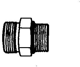
Straight Fitting
Straight Fitting
[1] - Inspect O-ring boss seat for dirt or defects.
[2] - Lubricate O-ring with petroleum jelly. Place electrical tape over threads to protect O-ring. Slide O-ring over tape and into O-ring groove of fitting. Remove tape.
[3] - Tighten fitting to torque value shown on chart.
Angle Fitting
Angle Fitting
[1] - Back-off lock nut (A) and back-up washer (B) completely to head-end (C) of fitting.

[2] - Turn fitting into threaded boss until back-up washer contacts face of boss.
[3] - Turn fitting head-end counterclockwise to proper index (maximum of one turn).
[4] -
→NOTE:
Do not allow hoses to twist when tightening fittings.
Hold fitting head-end with a wrench and tighten locknut and back-up washer to proper torque value.
→NOTE:
Torque tolerance is ± 10%.
Service Recommendations For Flat Face O-Ring Seal Fittings
[1] - Inspect the fitting sealing surfaces and O-ring. They must be free of dirt or defects.
[2] - Lubricate O-rings and install into grove using petroleum jelly to hold in place.
[3] - Index angle fittings and tighten by hand pressing joint together to insure O-ring remains in place.
[4] - Tighten fitting or nut to torque value shown on the chart. Do not allow hoses to twist when tightening fittings, use backup wrench on straight hose couplings.
IMPORTANT:
Tighten fittings to 150% of listed torque value if indexing is necessary or if fitting is attached to an actuating device.
Tighten fittings to 50% of listed torque value if used in aluminum housing. O-ring
Metric Cap Screw Torque Values Grade 7
→NOTE:
When bolting aluminum parts, tighten to 80% of torque specified in table.
Metric Cap Screw Torque Values Grade 7
Metric Bolt and Screw Torque Values
Metric Bolt and Screw
Metric Torque Values
Class 4.8
Class 8.8 or 9.8
Class 10.9
Class 12.9
Lubricated Dry [ “Dry” means plain or zinc plated without any lubrication, or M6 to M18 fasteners with JDM F13B, F13E or F13H zinc flake coating. ]
[ “Lubricated” [ “Lubricated” [ “Lubricated” [ “Lubricated” means coated with means coated with means coated with means coated with Bolt or Screw a lubricant such as engine oil, fasteners with
Lubricated Dry [ “Dry” means plain or zinc plated without any lubrication, or M6 to M18 fasteners with JDM F13B, F13E or F13H zinc flake coating. ]
Lubricated Dry [ “Dry” means plain or zinc plated without any lubrication, or M6 to M18 fasteners with JDM F13B, F13E or F13H zinc flake coating. ] a lubricant such as engine oil, fasteners with a lubricant such as engine oil, fasteners with Size phosphate and oil coatings, or M20 phosphate and oil coatings, or M20 phosphate and oil coatings, or M20 phosphate and oil coatings, or M20 and larger and larger and larger and larger fasteners with JDM fasteners with JDM fasteners with JDM fasteners with JDM F13C, F13F or F13J F13C, F13F or F13J F13C, F13F or F13J

F13C, zinc a lubricant such as engine oil, fasteners with ] ] ] ] N˙m lb.-in. N˙m lb.-in. N˙m lb.-in. N˙m lb.-in. N˙m lb.-in. N˙m lb.-in. N˙m lb.-in. N˙m lb.-in. M6 4.7 42 6 53 8.9 79 11.3 100 13 115 16.5 146 15.5 137 19.5 172 N˙m lb.-ft. N˙m lb.-ft. N˙m lb.-ft. N˙m lb.-ft. M8 11.5 102 14.5 128 22 194 27.5 243 32 23.5 40 29.5 37 27.5 47 35 N˙m lb.-ft. N˙m lb.-ft. N˙m lb.-ft. M10 23 204 29 21 43 32 55 40 63 46 80 59 75 55 95 70 N˙m lb.-ft. M12 40 29.5 50 37 75 55 95 70 110 80 140 105 130 95 165 120 M14 63 46 80 59 120 88 150 110 175 130 220 165 205 150 260 190 M16 100 74 125 92 190 140 240 175 275 200 350 255 320 235 400 300 M18 135 100 170 125 265 195 330 245 375 275 475 350 440 325 560 410 M20 190 140 245 180 375 275 475 350 530 390 675 500 625 460 790 580 M22 265 195 330 245 510 375 650 480 725 535 920 680 850 625 1080 800 M24 330 245 425 315 650 480 820 600 920 680 1150 850 1080 800 1350 1000 M27 490 360 625 460 950 700 1200 885 1350 1000 1700 1250 1580 1160 2000 1475 M30 660 490 850 625 1290 950 1630 1200 1850 1350 2300 1700 2140 1580 2700 2000 M33 900 665 1150 850 1750 1300 2200 1625 2500 1850 3150 2325 2900 2150 3700 2730 M36 1150 850 1450 1075 2250 1650 2850 2100 3200 2350 4050 3000 3750 2770 4750 3500
Torque values listed are for general use only, based on the strength of the bolt or screw. DO NOT use these values if a different torque value or tightening procedure is given for a specific application. For stainless steel fasteners or for nuts on U-bolts, see the tightening instructions for the specific application. Tighten plastic insert or crimped steel type lock nuts by turning the nut to the dry torque shown in the chart, unless different instructions are given for the specific application.
Shear bolts are designed to fail under predetermined loads. Always replace shear bolts with identical property class. Replace fasteners with the same or higher property class. If higher property class fasteners are used, tighten these to the strength of the original. Make sure fastener threads are clean and that you properly start thread engagement. When possible, lubricate plain or zinc plated fasteners other than lock nuts, wheel bolts or wheel nuts, unless different instructions are given for the specific application.
Unified Inch Bolt and Screw Torque Values
Unified Inch Bolt and Screw
Unified Inch Bolt and Screw Torque Values
SAE Grade 1
SAE Grade 2 [ Grade 2 applies for hex cap screws (not hex bolts) up to 6 in. (152 mm) long. Grade 1 applies for hex cap screws over 6 in. (152 mm) long, and for all other types of bolts and screws of any length. ]
Bolt or Screw Size
Lubricated [ “Lubricated” means coated with a lubricant such as engine oil, fasteners with phosphate and oil coatings, or 7/8 in. and larger fasteners with JDM F13C, F13F or F13J zinc flake coating. ]
Dry [ “Dry” means plain or zinc plated without any lubrication, or 1/4 to 3/4 in. fasteners with JDM F13B, F13E or F13H zinc flake coating. ]
SAE Grade 5, 5.1 or 5.2
Lubricated [ “Lubricated” means coated with a lubricant such as engine oil, fasteners with phosphate and oil coatings, or 7/8 in. and larger fasteners with JDM F13C, F13F or F13J zinc flake coating. ]
SAE Grade 8 or 8.2
Dry [ “Dry” means plain or zinc plated without any lubrication, or 1/4 to 3/4 in. fasteners with JDM F13B, F13E or F13H zinc flake coating. ]
Dry [ “Dry” means plain or zinc plated without any lubrication, or 1/4 to 3/4 in. fasteners with JDM F13B, F13E or F13H zinc flake coating. ]
Torque values listed are for general use only, based on the strength of the bolt or screw. DO NOT use these values if a different torque value or tightening procedure is given for a specific application. For plastic insert or crimped steel type lock nuts, for stainless steel fasteners, or for nuts on U-bolts, see the tightening instructions for the specific application. Shear bolts are designed to fail under predetermined loads. Always replace shear bolts with identical grade.
Replace fasteners with the same or higher grade. If higher grade fasteners are used, tighten these to the strength of the original. Make sure fastener threads are clean and that you properly start thread engagement. When possible, lubricate plain or zinc plated fasteners other than lock nuts, wheel bolts or wheel nuts, unless different instructions are given for the specific application.
Group 15 - Fuel and Lubricants
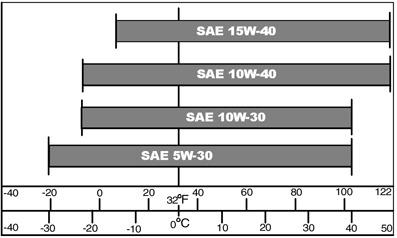
Engine Oil
Use oil viscosity based on the expected air temperature range during the period between oil changes.
Oil Chart
The following John Deere oils are preferred:
TURF-GARD™ PLUS- 4™
Other oils may be used if above John Deere oils are not available, provided they meet the following specification: API Service Classification SJ or higher
Oil Filters
Filtration of oils is critical to proper operation and lubrication. Always change filters regularly as specified in this manual. Use filters meeting John Deere performance specifications.
Gasoline Fuel for 4-Cycle Engines
Use unleaded gasoline with a minimum octane rating of 87 AKI (anti-knock index) or 90 RON (research octane number). Gasoline fuels specified to EN 228 or ASTM D4814 are recommended.
Fuel blends of unleaded gasoline with a maximum 10% ethanol or 15% MTBE (methyl tertiary-butyl ether) are also acceptable.
CAUTION:
Reduce the risk of fire. Handle fuel carefully. DO NOT fill the fuel tank when the engine is running or hot. Stop engine and allow it to cool for several minutes before filling fuel tank. Fill fuel tank only to the bottom of the filler neck.
Refuel outdoors. DO NOT smoke while you fill the fuel tank or service the fuel system. Store fuel in properly identified polyethylene containers.
When storing fuel, add John Deere Gasoline Conditioner and Stabilizer (or equivalent) at the specified concentration.
IMPORTANT:
DO NOT use methanol or fuel blends that contain methanol.
Avoid spilling fuel. Gasoline can damage plastic and painted surfaces.
DO NOT mix oil with gasoline.