8 minute read
Group 25 SEPARATION


SEPARATlN€ BETWEEN ENGINEANDTRACTOR FRONT END
REMOVAL
Advertisement
For safety disconnect battery cable. Remove front end weights (if equipped). Remove radiator and fuel tank caps. Remove radiator side grilles and hood. Install radiator and fuel tank caps. Remove side frames.
Gose fuel shut-off valve at bottom of fuel tank.
Disconnect fuelinlet line at fuel tank andtransfer pump. Remove transfer pump and fuel inlet line.
Disconnect air intake pipe 6 at intake manifold of engine.
Drain coolant and disconnect upper and lower water hose at radiator.
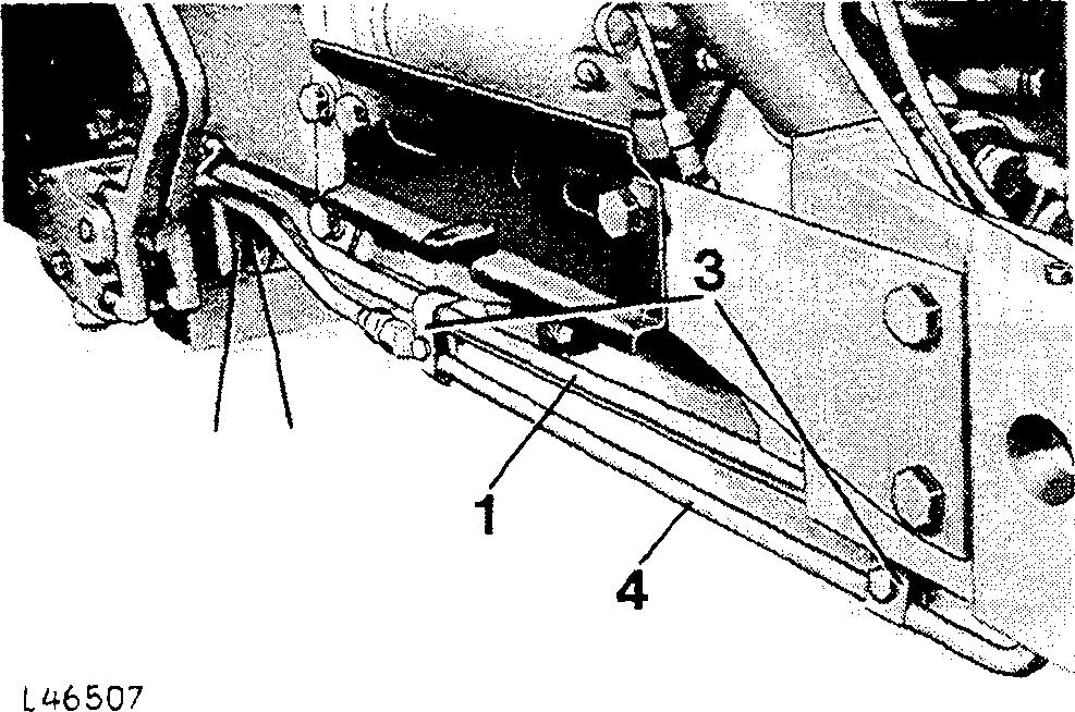
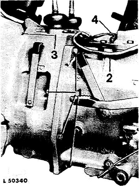
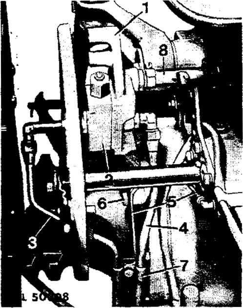
3 (fig. 2). Remove cap screw 5 and retainer 2 for attaching suction line l to
NOTE: Plug lines and openings immediatel y with plugs or caps.
Disconnect drag link at bell crank. Securely support rear of tractor under clutch housing.
Insert wood blocks between front axle and front support to prevent the latter from tipping sideways.
Attach front of tractor to a suitable hoist.
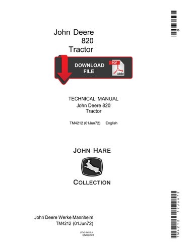
Remove cap screws 1 (fig. 1) of front support and separate front end from engine. Take measures to prevent front of tractor from tipping to the front. If tank contains too much fuel, drain it or safely support front of tractor.
CAUTION: Move front end forward out of tractor until pump drive shaft comes loose of front or rear coupling of pump drive.
Installation
Install hydraulic pump drive shaft into front coupling. Make sure both dowels are in place on front support.
Move front of tractor toward engine. Be sure to install hydraulic pump drive shaft in rear coupling, and to install suction line1 (fig.2) inclutch housing.
Attach front end of tractor to engine, using cap screws 1 (fig. 1). Tighten screws to the specified torque.
Model 820 Tractor TM-4212 (Jan-70)
Install retainer 2 (fig. 2) of suction line 1 and tighten cap screw 5 of retainer to the specified torque. Connect pressure line 4.
NOTE: yor proper sealing o[ suction line, place a newO-ringinclutchhousing bore.
Install fuel transfer pump and connect fuel lines. Make sure transfer pump inlet line is below and behind fuel pressure line.
Open fuel shut-off valve.
Connect wire to fuel gauge sending unit.
Connect headlight wires to junctions.
Attach water hoses to radiator.
Attach air intake pipe to intake manifold.
Install clamps of hydraulic lines
Attach drag link to bell crank and tighten slotted nut to the specified torque.
Install hood and radiator side grilles.
Fill radiator with clear, soft water, adding an antifreeze-rust inhibitor mixture (see Operator's Manual).
Connect ground cable to batteries.
CAUTION: Always connect ground cable to negative (-) polesof batteries.
Start engine and check fuel lines, hydraulic lines and water hoses for possible leaks.
Removingandinstalling Engine
NOTE: for most engine service operations the engine need not be removed. Hou›ever, i[ the crankshaft has to be removed or in case o/ mojor overhaul, remove engine.
REMO¥’AL
Porsafety disconnect groundcableatbatteries.
Separate front of tractor ftom engine, as explained above.
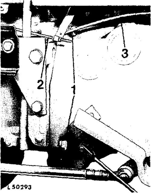
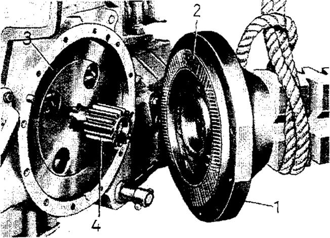
Disconnect all cables to dashboard at regulator andall cables 4(fig.3) at starter.
Disconnect cableatoilpressureswitch3.
1 En@ne atacRag 9ozews 3 Ofipreswze swdeb
2 £Jexi4e sbaf¢ of txcbomeer 4 Surfer cable in tractors uiith Thermostart aid: Disconnect cableatheaterof intakemanifold.
Remove flexible shaft 2 (fig. 3) of tachometer from clutch housing and cam shaft. Replace rubber seal of flexible shaft, if required (seal will possibly remaininhousing bore).
Remove cap screws S attaching dash to flywheel housing.
Disconnect wireatsignalhorn.
On tractors wit A starting ftuid adapter: Disconnect startingfluidlineatintakemanifold.
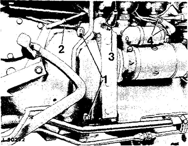
Disconneci speedcontrolrod2(Fig.41atinjection pump
On trocfors with BOiSCH or ROTO DUBEI injection putrip: Disconnect shut-off cable at the pump.
On tmetors with ROOiSA MAS!TER model CB i•ieetiOn R* p1 Disconnect shut-off cable at the pump.
Screw retaining screw of flexible tube of coolant temperature gauge out of cylinder head and withdraw flexibletubefromcylinder head.
Remove left dashpanel as well as both batteries. Remove cap screws attaching dashboard to flywheelhousing.
Attach JD 244-1 and 244-2 engine lifting eyes to cylinder head and attachenginetoasuitablehoist.
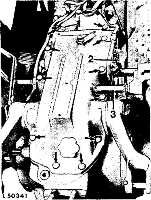
Remove cap screws 1 (tigs. 3 and 4) attaching flywheelhousingtoclutchhousing.
Liftengine outfront by meansof thehoist.
CAUTION: Move engine properly in line with drive shaft and hollow drive shaft until these shafts come loose of the driven disks of the engine dual-stage clutch.
Installation
Align engine properly with drive shaft and hollow drive shaft and move toward rear Of tractor. Align splines of both shafts with internal threads of driven disks. Also align screw holes of flywheel housing with screw holes of clutch housing. Slide engine evenly toward clutch housing, inserting two dowels of flywheel housing in bores of clutch housing until engine fully contacts clutch housing.
CAUTION: Make sure flywheel housing is flush against clutch housing before tightening screws. Then tighten attaching screws to the specified torque.
Secure dash to flywheel housing.
Connect speed control rod to injection pump.
On tractors with BOSCH or ROTO DIESEL in/ection pump: Attach shut-off cable to pump.
On tractors with ROOSA MASTER model CB iriJectioti pump: Connect shut-off cable to pump.
Model 820 Tractor
TM-4212 (Jan-70) lnsert flexible tube of coolant temperature gauge in cylinder head and tighten retaining screw.
Connect cables to regulator and starting motor and connect cable to oil pressure switch.
Connect cable to signal horn.
Install both batteries.
CAUTION: Connect battery cable to positive poles of batteries.
Lubricate rubber seal of tachometer flexible shaft and attach shaft to clutch housing (see 2, fig. 3). Make sure driving tab of flexible shaft engages in slot of camshaft. Do not tighten excessively to avoid damage to the seal resulting in leakage.
On tractors north starting fluid adapter: Connect starting fluid line to intake manifold.
On tractors with Thermostart aid: Connect Thermostart aid wire to heater in intake manifold.
Attach front of tractor to engine.
CAUTION: Connect ground cables of batteries to negative (-) poles.
NOTE: I f engine has been overhauled, tune up engineasexplained ingroup 20.
REMOVALAND lNSTALLATlON OFCLUTCH HOUSING
NOTE: !Separating and attaching o/ engine and Separate engine from clutch housing as explained clutch housing as uiell as of clx tcJt housing and under ”REMOVING ENGINE”; the tractor front transmission case is explained below. JPhere the end may remain attached to the engine. tractor is to be separated depends on the individual repair operation. I{, e.g., repair worn has to be carried out on the transmission, separation Remove clamps 3 (fig. 2), cap screw 5 and retainer between the clutch housing and the transmission 2 for fastening suction line 1 to front clutch case will besufficient. housing. Disconnect pressure line 4 (fig. 2) at connector.
Removal
Disconnect battery ground cables. Drain transmission oil.
Disconnect drag link at bell crank.
Insert wood blocks between front axle and front support to prevent front support from tipping sideways.
Safely support rear end of tractor.
Attach tractor front end and engine to a suitable hoist and remove attaching screws 1 between engine and clutch housing (see figs. 3 and 4).
Roll engine and tractor front end away from clutch housing.
Remove oil line of front quick coupler (if provided). Remove right footrest.
Disconnect brake lines at brake valve and cylinder. Remove transmission shield.
Remove clamp of pump pressure line at clutch housing.
Remove transmission shift cover 3 (fig. 5).
Remove transmission oil filter.
Remove cap screws 1 (fig. 5) on both sides and both inner cap screws. Separate clutch housing from transmission case.
Discard seal rings provided between the two housings.
NOTE: Be sure ball and spring provided on some po wersho/f t y pes do not get lost (see section 50, group25).
Installation
Install new seal rings in clutch housing front facing transmission case.
Slide clutch housing against transmission case.
Slide PTO drive shaft into bore of front PTO shaft or (if front PTO is not provided) into bore of quill. Make sure spring and ball provided on some powershaft types are installed in PTO drive shaft or quill or front powershaft. Align clutch housing with centerline of PTO drive shaft and slide against transmission case. Mesh powershaft gears with splines of hollow PTO drive shaft.
Make sure clutch housing is flush against transmission case before tightening cap screws to the specified torque.
NOTE: If clutch housing has also been separated from engine, assemble a8 explained under ”Installation of Engine.”
Install suction line 1 (fig. 2) in bore of clutch housing and secure by means of screw and retainer. Tighten cap screw to the specified torque. Connect front section of pressure line 4 (fig. 2) to rear section. Then install both pipe clamps 3.
NOT£: For proper sealing of suction line, insert new O-ring inboreo[clutchhousing.
As regards further installation operations reverse removal procedure.
Removal And Installation Of Final Drives
Disconnect pilot line 5 (fig.6) at dump valve and rockshaft and remove. Remove clamp 7. NOTE. The removal o[ both final driues is explained below. I f onI y one final drive is to be removed, remove only one wheel, wiring harness etc.
Removal
Forsafetydisconnect groundcableatbatteries.
Lift up rear of tractor by means of a car jack or hoistandremoverearwheels.
CAUTION: Support transmission safely to prevent tipping of tractor.
Disconnect both rear wiring harnesses at connectors.
Removerearfender.
Disconnect cables at brake warning switch located inleft-handrearaxlehousing.
Disconnect brake lines on bothrear axlehousings.
Disconnect both pressure lines 3 and 4 at elbows and return line 8 oil manifold 1. On tractors with selective control valve disconnect line to quick coupler at control valve. Remove two cap screws 6 attaching oil manifold 1 to right final drive housing. Lift off oil manifold with pressure control valveandselectivecontrol valve(ifequipped),
Cover connections and exposed openings with plastic plugs or caps to keep out foreignparticles.
8
Attach tinal drive to hoist. Remove finn dnve attaching screws and pull final drive housing from transmission case. Withdraw housing evenly until final drive shaft gear is no longer in mesh with planetary gearsof finaldrive.
Installation
NOTE: I f the bra he dish and the ”Roofing” facing mere removed, install bonded two-layer {acing so that the brass- interwoven upper layer faces the brake curface of the transmission case.
Position new gasket between final drive housing andtransmission case.
Attach final drives to transmission case by means of asuitable hoist. Make sure finaldriveshaftgear indexes with planetary gears and that thedowels areproperlyaligned.
Tighten final drive attaching screws to the specifiedtorque.
Attachoilmanifoldwithpressurecontrolvalve and Install rear fenders. Connect lines of wiring selective control valve (if equipped) to final drive harnesses toconnectors. housing.
Connect all oil lines and install pipe clamp.
Connect brake linesand bleedbrakes,asexplained insection 60,group15.
Connect cable to brake warning switch, Install rear wheels and tighten to the specified torque.
CAUTION: Tighten ground cable to negative (-) poles of batteries.
Removal Andinstallation Ofrockshaft
REMOVAL
IMPORTANT: Work on the hydraulic system requires extreme care and cleanliness. Minute dirt or foreign particles, scratches, nicks or burrs may put the hydraulic system out of function. Before removingtherockshaft,checkhydraulicsystemfor leaks.
For safery, disconnect ground cable from batteries.
Remove transmission shield. Disconnect line l (fig. 8)of starter safety switch.
Remove operator's seat. Disconnect both lift links at lift arms.
Loosen clamp of oil return hose S (fig, 8) facing rockshaft andmoveaside.
Disconnect lines of rear quick couplers (if equipped) atselectivecontrolvalves.
Disconnect pilot line 2 (big. 8) at elbow on rockshaft.
Free both rear wiring harnesses.
Move selector lever in position ”L” so that the control linkage roller slides along the cam of the controlarmwhenremoving therockshaft. Attach engine lifting eye No. JD 244-2 to top of rockshaft housing.
Removerockshaftattachingscrews(seearrowsin fig. 8). Lift rockshaft assemblé off transmission case by means of a hoist. Withdraw oil return line 3 from rockshaft adapter.
Take care not to damage two rear harnesses.
NOTE: A[ter removing rochsha[t, couer transmission case to prevent (oreign particles /rotn [alling into the transmission.
Installation
Use a new gasket between transmission case and rockshaft. Make sure dowels in transmission case and seal ring of oü înlet passage are installed.
Move selector lever in position ”L” so that the control linkage with roller can be slided over the cam.
Liftrockshaftontransmissioncase,usingasuitable hoist.