14 minute read
Diesel Engines Base Engine


Technical Manual
POWERTECH 8.1 L Diesel Engines —
Advertisement
Base Engine
CTM86 06JUL06 (ENGLISH)
For complete service information also see:

POWERTECH 8.1 L Diesel Engines Mechanical Fuel Systems . . . . . .
POWERTECH 6.8 L & 8.1 L Diesel
POWERTECH 8.1 L Diesel Engines Level 9
Electronic Fuel Systems with Denso In-Line Pump
CTM134
CTM243 Engines Level 3 Electronic Fuel Systems with Bosch In-Line Pump
Foreword
This manual is written for an experienced technician. Essential tools required in performing certain service work are identified in this manual and are recommended for use.
This manual (CTM86) covers only the base engine. It is one of five volumes on 8.1 L engines. The following four companion manuals cover fuel system repair and diagnostics:
• CTM243 Mechanical Fuel Systems
• CTM134 Level 3 Electronic Fuel Systems
• CTM255 Level 9 Electronic Fuel Systems
• CTM68 Electronic Injection Fuel Systems
Other manuals will be added in the future to provide additional information on electronic fuel systems as needed.
This manual covers the base engine for all 8.1L engines, including emission non-certified, Tier I certified, and Tier II certified (esn 200,000 ).
Live with safety: Read the safety messages in the introduction of this manual and the cautions presented throughout the text of the manual.
This is the safety-alert symbol. When you see this symbol on the machine or in this manual, be alert to the potential for personal injury.
Use this component technical manual in conjunction with the machine technical manual. An application listing in the introduction identifies engine-models/applications. See the machine technical manual for information on engine removal and installation, and gaining access to engine components.
Information is organized in sections and groups for the various components requiring service instruction. At the end of the book are summary listings of all applicable essential tools, service equipment, and other materials needed to do the job, service parts kits, specifications, wear tolerance, and torque values.
Before beginning repair on an engine, clean the engine and mount on a repair stand. (See CLEAN ENGINE in Group 010 and see MOUNT ENGINE ON REPAIR STAND in Group 010..)
This manual contains SI Metric units of measure followed immediately by the U.S. Customary units of measure. Most hardware on these engines is metric sized.
Some components of this engine may be serviced without removing the engine from the machine. Refer to the specific machine technical manual for information on components that can be serviced without removing the engine from the machine and for engine removal and installation procedures.
Read each block of material completely before performing service to check for differences in procedures that apply to the engine model number you are working on. If only one procedure is given, that procedure applies to all the engines in the manual.
Component Technical Manuals are concise service guides for specific components. Component technical manuals are written as stand-alone manuals covering multiple machine applications.
Fundamental service information is available from other sources covering basic theory of operation, fundamentals of troubleshooting, general maintenance, and basic types of failures and their causes.
CALIFORNIA PROPOSITION 65 WARNING: Diesel engine exhaust and some of its constituents are known to the State of California to cause cancer, birth defects, and other reproductive harm.
John Deere Dealers
The changes listed below make your CTM obsolete. Repair, operation, and diagnostics are now covered in five manuals. Discard CTM86 dated 06JUL99 and replace with the following new manuals:
• CTM86 Base Engine
• CTM243 Mechanical Fuel Systems
• CTM134 Level 3 Electronic Fuel Systems
• CTM255 Level 9 Electronic Fuel Systems
• CTM68 Electronic Fuel Injection Systems
Also, copy these pages and route through your Service Department.
SECTION 01, GROUP 001 (Engine Identification)
• Updated engine model designation chart.
• Updated engine application charts.
SECTION 01, GROUP 002 (Fuels, Lubricants, and Coolants)
• Updated engine oil and coolant application guidelines.
SECTION 02, GROUP 010 (Engine Rebuild)
• Updated engine disassembly sequence.
• Updated engine assembly sequence.
• Updated sealant application guidelines.
SECTION 02, GROUP 020 (Cylinder Head and Valves Repair and Adjustment Serial Number ( 199,999)
• Repair procedures for cylinder head and valves on engines with serial number ( 199,999) are covered in this group.
SECTION 02, GROUP 021 (Cylinder Head and Valves Repair and Adjustment Serial Number (200,000— )
• Repair procedures for cylinder head and valves on engines with serial number (200,000 ) are covered in this group.
SECTION 02, GROUP 050 (Camshaft and Timing Gear Train Repair and Adjustment)
• Eliminated procedure to check valve lift. Use appropriate procedure from Group 020 or Group 021.
• Revised specifications for installation of crankshaft gear-driven auxiliary drive.
• Revised procedure for installation of thrust washer and timing gear cover.
SECTION 02, GROUP 060 (Lubrication System Repair and Adjustment)
• Added information for top-load oil filter.
SECTION 02, GROUP 070 (Cooling System Repair and Adjustment)
• Added belt routing diagrams.
• Revised procedure for installation of coolant pump.
SECTION 02, GROUP 080 (Air Intake and Exhaust System Repair and Adjustments)
• Revised procedure for turbocharger inspection techniques.
• Eliminated procedure for adjusting turbocharger wastegate actuator.
• Revised specifications for installing turbocharger.
SECTION 02, GROUP 090 (Fuel System Repair and Adjustments)
NOTE: Repair procedures for fuel systems have been have been moved to Section 02, Group 090 in the three following technical manuals:
• CTM243 Mechanical Fuel Systems
• CTM134 Level 3 Electronic Fuel Systems
• CTM255 Level 9 Electronic Fuel Systems
SECTION 02, GROUP 100 (OEM Starting and Charging Systems)
• Starting and charging systems are covered in this new group.
SECTION 03, GROUP 120 (Base Engine Operation)
• Base engine theory of operation is covered in this new group.
NOTE: Fuel system theory of operation has been moved to Section 03 in the three following technical manuals:
• CTM243 Mechanical Fuel Systems
• CTM134 Level 3 Electronic Fuel Systems
• CTM243 Mechanical Fuel Systems
• CTM134 Level 3 Electronic Fuel Systems
• CTM255 Level 9 Electronic Fuel Systems
SECTION 05 (Tools and Other Materials)
• All essential tools, service tools, dealer fabricated tools, and other materials listed throughout this manual are consolidated in this section for ease of reference.
SECTION 06 (Specifications)
• All repair, test, and diagnostic specifications listed
• CTM255 Level 9 Electronic Fuel Systems throughout this manual are consolidated in this section for ease of reference.
SECTION 04, GROUP 150 (Observable Diagnostics
• Updated bolt and cap screw torque values. and Tests)
• Base engine observable diagnostics and tests are
• Updated General OEM specifications.
• Updated dynamometer specifications.
• Updated turbocharger boost specifications covered in this new section/group.
NOTE: Fuel system diagnostics and testing has been moved to Section 04 in the three following technical manuals:
About this Manual
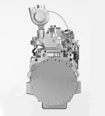
This component technical manual (CTM) covers the base engine for POWERTECH 8.1 L (494 cu. in.) diesel engines produced in Waterloo, Iowa. This manual’s coverage includes: emissions non-certified, emissions certified Tier I, and emissions certified Tier II (esn 200,000 ) engines
This manual is a complete revision of CTM86 (06JUL99). Replace earlier manual with the following new manuals:
• CTM86 POWERTECH 8.1 L Diesel Engines Base Engine
• CTM243 POWERTECH 8.1 L Diesel Engines Mechanical Fuel Systems
• CTM134 POWERTECH 6.8 L & 8.1 L Diesel Engines Level 3 Electronic Fuel Systems with Bosch In-Line Pump
• CTM255 8.1 L Diesel Engines Level 9 Electronic Fuel Systems with Denso In-Line Pump
• CTM68 Electronic Fuel Injection Systems
Direction of engine crankshaft rotation in this manual is referenced as clockwise, as viewed from the rear of the engine. Front of engine is fan drive end.
Read each procedure completely before performing any service.
IMPORTANT: For repair, diagnostics, and testing procedures on the fuel system, refer to the companion manuals:
• CTM243 — POWERTECH 8.1 L Diesel Engines Mechanical Fuel Systems
• CTM134 — POWERTECH 6.8 L & 8.1 L
Diesel Engines Level 3 Electronic Fuel Systems with Bosch In-Line Pump
• CTM255 8.1 L Diesel Engines Level 9 Electronic Fuel Systems with Denso In-Line Pump
• CTM68 Electronic Fuel Injection Systems
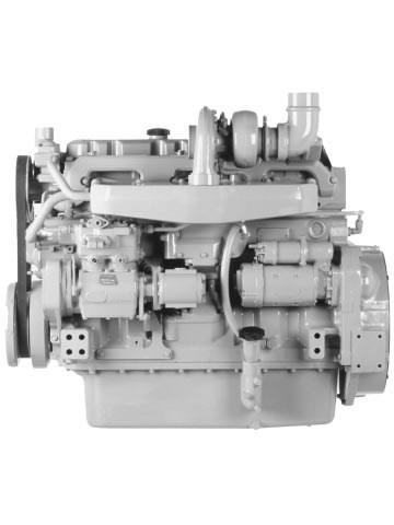
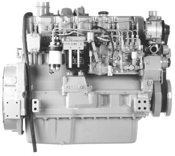
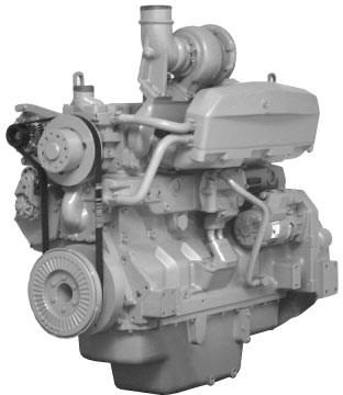
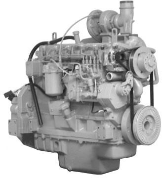
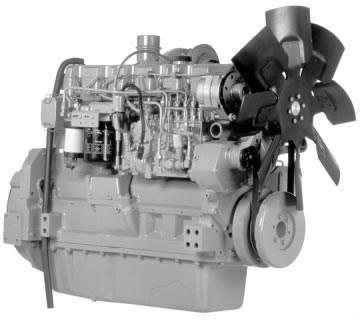
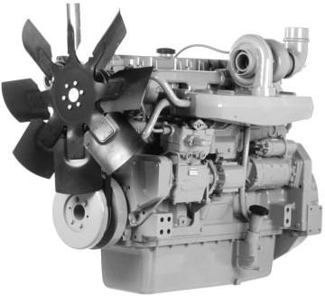
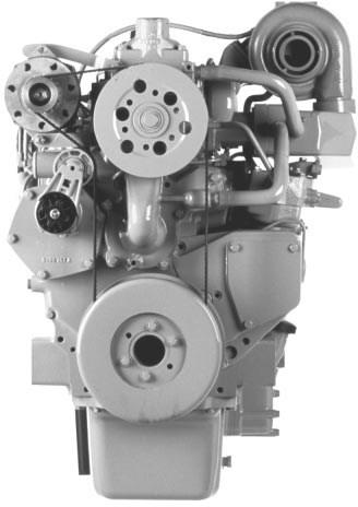
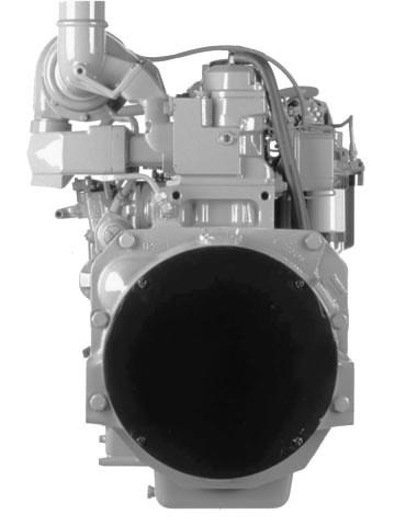
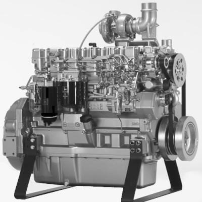
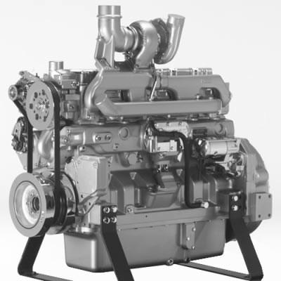
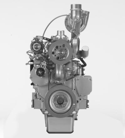
Identification Views Serial Number ( 199,999) Non Emissions Certified, and Tier I Emissions Certified Engines
SECTION 01—General
Group 000 Safety
Group 001 Engine Identification
Group 002 Fuels, Lubricants and Coolant
SECTION 02 Repair and Adjustments
Group 010 Engine Rebuild
Group 020 Cylinder Head and Valves Repair and Adjustment S. N. ( 199,999)
Group 021 Cylinder Head and Valves Repair and Adjustment S. N. (200,000 )
Group 030 Cylinder Block, Liners, Pistons, and Rods Repair and Adjustment
Group 040 Crankshaft, Main Bearings and Flywheel Repair and Adjustment
Group 050 Camshaft and Timing Gear Train Repair and Adjustment
Group 060 Lubrication System Repair and Adjustment
Group 070 Cooling System Repair and Adjustment
Group 080 Air Intake and Exhaust System Repair and Adjustment
Group 100 OEM Starting and Charging Systems Repair and Adjustment
SECTION 03—Theory of Operation
Group 120 Base Engine Operation
SECTION 04 Diagnostics
Group 150 Observable Diagnostics and Tests
SECTION 05 Tools and Other Materials Group 170 Repair Tools and Other Materials
Group 180 Diagnostic Service Tools
Group 190 Dealer Fabricated Service Tools
SECTION 06—Specifications
Group 200 Repair and General OEM Specifications
Group 210 Diagnostic Specifications
All information, illustrations and specifications in this manual are based on the latest information available at the time of publication. The right is reserved to make changes at any time without notice.
Handle Fluids Safely—Avoid Fires
When you work around fuel, do not smoke or work near heaters or other fire hazards.
Store flammable fluids away from fire hazards. Do not incinerate or puncture pressurized containers.
Make sure machine is clean of trash, grease, and debris.
Do not store oily rags; they can ignite and burn spontaneously.
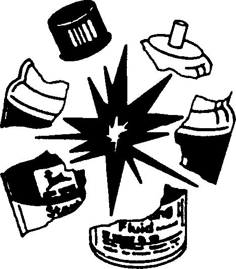
Handle Starting Fluid Safely
Starting fluid is highly flammable.
Keep all sparks and flame away when using it. Keep starting fluid away from batteries and cables.
To prevent accidental discharge when storing the pressurized can, keep the cap on the container, and store in a cool, protected location.
Do not incinerate or puncture a starting fluid container.
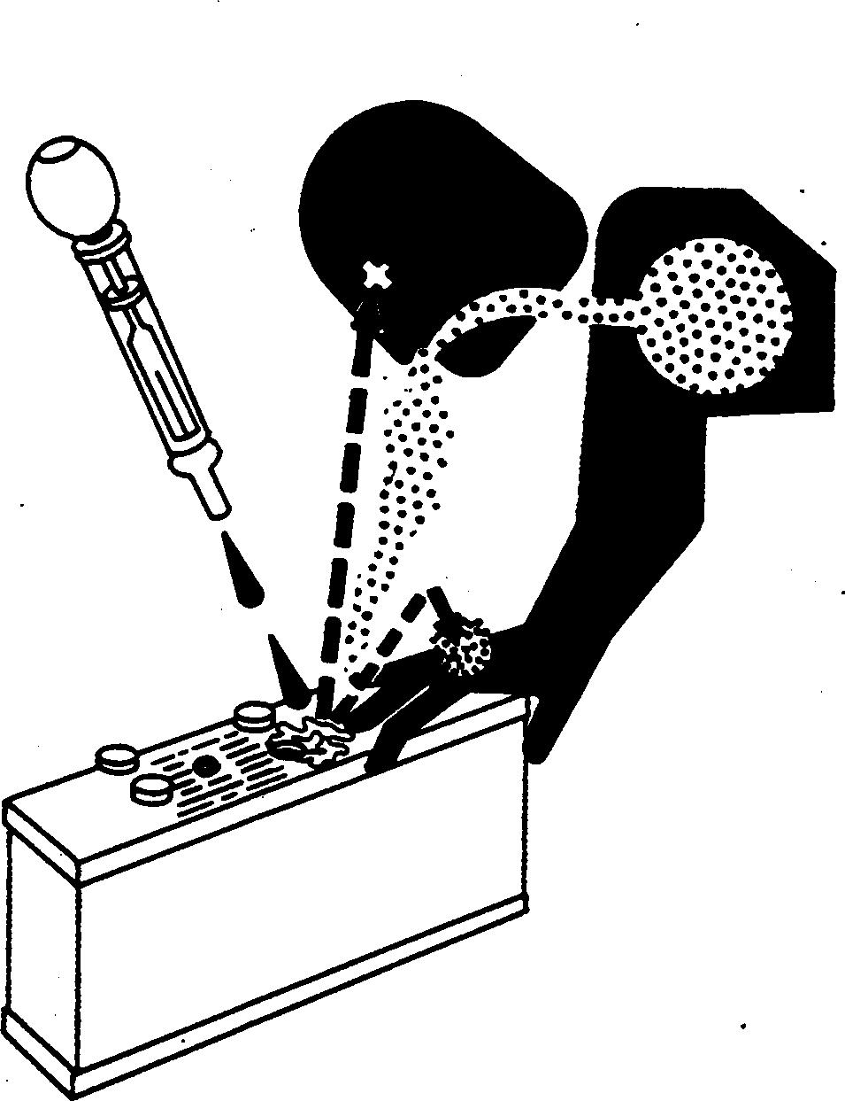
CAUTION: Battery gas can explode. Keep sparks and flames away from batteries. Use a flashlight to check battery electrolyte level.
Never check battery charge by placing a metal object across the posts. Use a voltmeter or hydrometer.
Always remove grounded (-) battery clamp first and replace it last.
Do not charge a frozen battery; it may explode. Warm battery to 16C (60F).
CAUTION: Sulfuric acid in battery electrolyte is poisonous. It is strong enough to burn skin, eat holes in clothing, and cause blindness if splashed into eyes.
Avoid the hazard by:
1. Filling batteries in a well-ventilated area.
2. Wearing eye protection and rubber gloves.
3. Avoiding breathing fumes when electrolyte is added.
4. Avoiding spilling or dripping electrolyte.
5. Use proper jump start procedure.
If you spill acid on yourself:
1. Flush your skin with water.
2. Apply baking soda or lime to help neutralize the acid.
3. Flush your eyes with water for 15—30 minutes. Get medical attention immediately.
If acid is swallowed:
1. Do not induce vomiting.
2. Drink large amounts of water or milk, but do not exceed 2 L (2 quarts).
3. Get medical attention immediately.
WARNING: Battery posts, terminals, and related accessories contain lead and lead compounds, chemicals known to the State of California to cause cancer and reproductive harm. Wash hands after handling.
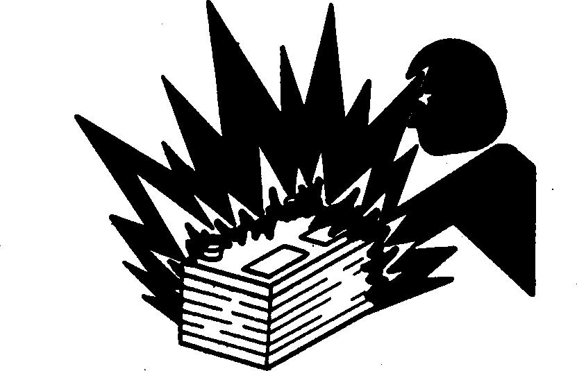
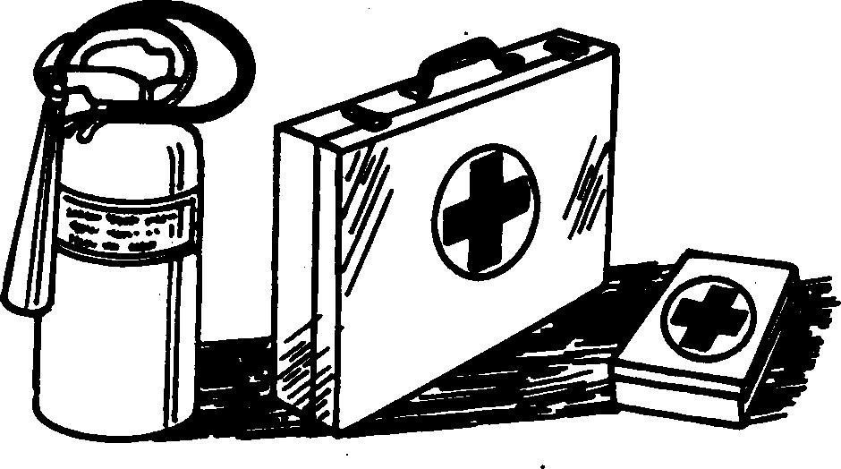
Prepare for Emergencies
Be prepared if a fire starts.
Keep a first aid kit and fire extinguisher handy. Keep emergency numbers for doctors, ambulance service, hospital, and fire department near your telephone.
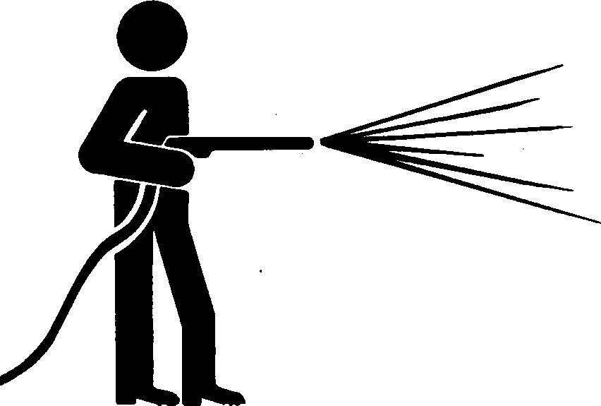
Avoid High-Pressure Fluids
Escaping fluid under pressure can penetrate the skin causing serious injury.
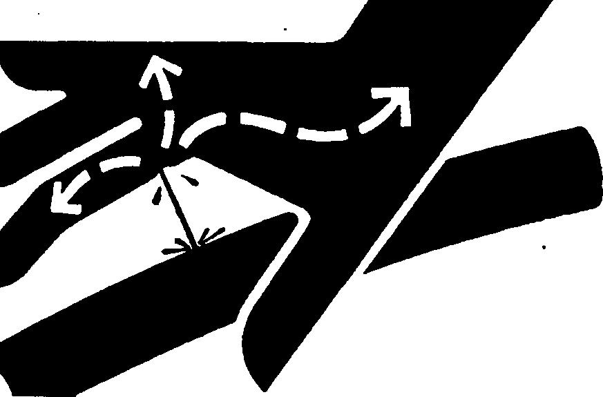
Avoid the hazard by relieving pressure before disconnecting hydraulic or other lines. Tighten all connections before applying pressure.
Search for leaks with a piece of cardboard. Protect hands and body from high pressure fluids.
If an accident occurs, see a doctor immediately. Any fluid injected into the skin must be surgically removed within a few hours or gangrene may result. Doctors unfamiliar with this type of injury should reference a knowledgeable medical source. Such information is available from Deere & Company Medical Department in Moline, Illinois, U.S.A.
CTM86 (06JUL06)
Wear Protective Clothing
Wear close fitting clothing and safety equipment appropriate to the job.
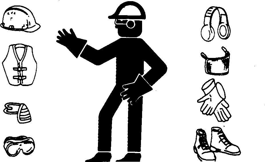
Prolonged exposure to loud noise can cause impairment or loss of hearing.
Wear a suitable hearing protective device such as earmuffs or earplugs to protect against objectionable or uncomfortable loud noises.
Operating equipment safely requires the full attention of the operator. Do not wear radio or music headphones while operating machine.
Service Machines Safely
Tie long hair behind your head. Do not wear a necktie, scarf, loose clothing, or necklace when you work near machine tools or moving parts. If these items were to get caught, severe injury could result.

Remove rings and other jewelry to prevent electrical shorts and entanglement in moving parts.
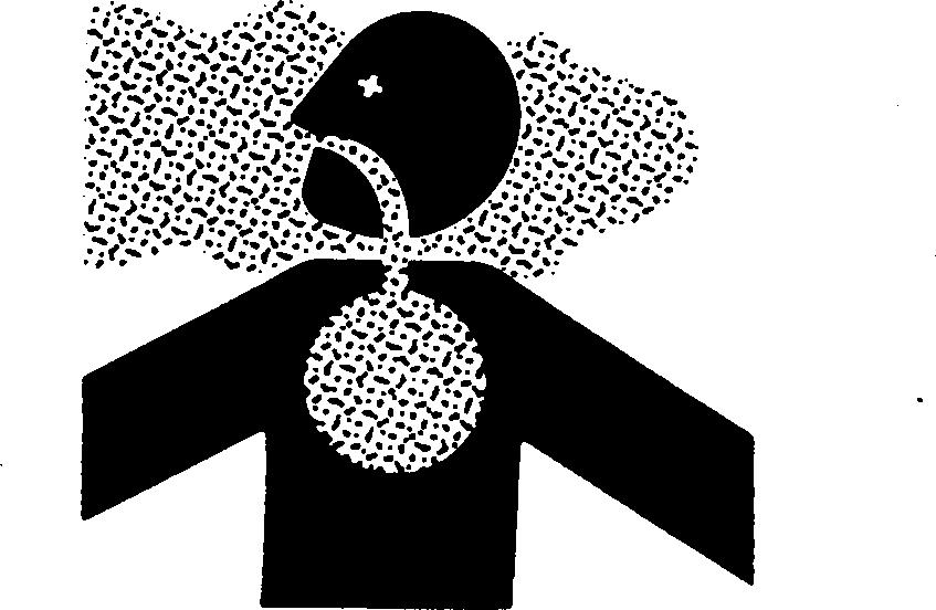
Work In Ventilated Area
Engine exhaust fumes can cause sickness or death. If it is necessary to run an engine in an enclosed area, remove the exhaust fumes from the area with an exhaust pipe extension.
If you do not have an exhaust pipe extension, open the doors and get outside air into the area
Work in Clean Area
Before starting a job:
• Clean work area and machine.
• Make sure you have all necessary tools to do your job.
• Have the right parts on hand.
• Read all instructions thoroughly; do not attempt shortcuts.
Install Fan Guards
Rotating cooling system fans can cause serious injury.

Keep fan guards in place at all times during engine operation. Wear close fitting clothes. Stop the engine and be sure fan is stopped before making adjustments or connections, or cleaning near the front of the engine.
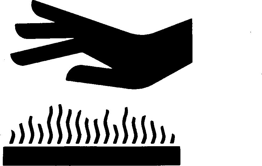
Avoid Hot Parts
Avoid skin contact with exhaust manifolds, turbochargers and mufflers. Keep flammable materials clear of the turbocharger.
External dry exhaust parts become very hot during operation. Turbochargers may reach temperatures as high as 500C (932F) under full load, and naturally aspired exhaust manifolds may reach 600C (1112F) under full load. This may ignite paper, cloth or wooden materials. Parts on engines that have been at full load and reduced to no load idle will maintain approximately 150C (302F).
CTM86 (06JUL06)
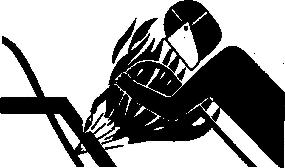
Remove Paint Before Welding or Heating
Avoid potentially toxic fumes and dust.
Hazardous fumes can be generated when paint is heated by welding, soldering, or using a torch.
Remove paint before heating:
• Remove paint a minimum of 100 mm (4 in.) from area to be affected by heating. If paint cannot be removed, wear an approved respirator before heating or welding.
• If you sand or grind paint, avoid breathing the dust. Wear an approved respirator.
• If you use solvent or paint stripper, remove stripper with soap and water before welding. Remove solvent or paint stripper containers and other flammable material from area. Allow fumes to disperse at least 15 minutes before welding or heating.
Do not use a chlorinated solvent in areas where welding will take place.
Do all work in an area that is well ventilated to carry toxic fumes and dust away.
Dispose of paint and solvent properly.
Avoid Heating Near Pressurized Fluid Lines
Flammable spray can be generated by heating near pressurized fluid lines, resulting in severe burns to yourself and bystanders. Do not heat by welding, soldering, or using a torch near pressurized fluid lines or other flammable materials. Pressurized lines can accidentally burst when heat goes beyond the immediate flame area.
Illuminate Work Area Safely
Illuminate your work area adequately but safely. Use a portable safety light for working inside or under the machine. Make sure the bulb is enclosed by a wire cage. The hot filament of an accidentally broken bulb can ignite spilled fuel or oil.
Use Proper Lifting Equipment
Lifting heavy components incorrectly can cause severe injury or machine damage.

Follow recommended procedure for removal and installation of components in the manual.
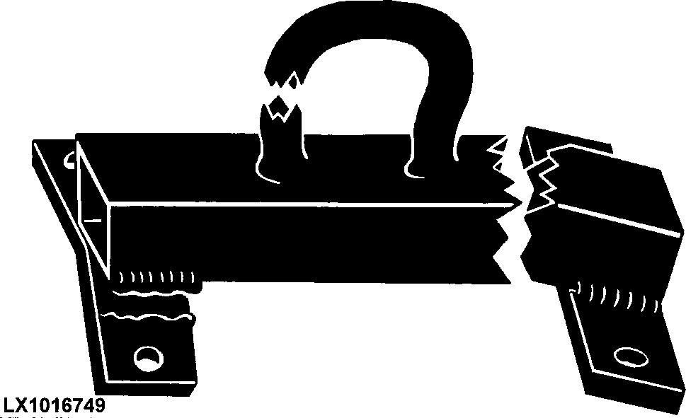
Construct Dealer-Made Tools Safely
Faulty or broken tools can result in serious injury. When constructing tools, use proper, quality materials and good workmanship.
Do not weld tools unless you have the proper equipment and experience to perform the job.
Understand service procedure before doing work. Keep area clean and dry.
Never lubricate, service, or adjust machine while it is moving. Keep hands, feet , and clothing from power-driven parts. Disengage all power and operate controls to relieve pressure. Lower equipment to the ground. Stop the engine. Remove the key. Allow machine to cool.
Securely support any machine elements that must be raised for service work.
Keep all parts in good condition and properly installed. Fix damage immediately. Replace worn or broken parts. Remove any buildup of grease, oil, or debris.
On self-propelled equipment, disconnect battery ground cable (-) before making adjustments on electrical systems or welding on machine.
On towed implements, disconnect wiring harnesses from tractor before servicing electrical system components or welding on machine.
Use Proper Tools
Use tools appropriate to the work. Makeshift tools and procedures can create safety hazards.

Use power tools only to loosen threaded parts and fasteners.
For loosening and tightening hardware, use the correct size tools. DO NOT use U.S. measurement tools on metric fasteners. Avoid bodily injury caused by slipping wrenches.
Use only service parts meeting John Deere specifications.

Dispose of Waste Properly
Improperly disposing of waste can threaten the environment and ecology. Potentially harmful waste used with John Deere equipment include such items as oil, fuel, coolant, brake fluid, filters, and batteries.
Use leakproof containers when draining fluids. Do not use food or beverage containers that may mislead someone into drinking from them.
Do not pour waste onto the ground, down a drain, or into any water source.
Air conditioning refrigerants escaping into the air can damage the Earth’s atmosphere. Government regulations may require a certified air conditioning service center to recover and recycle used air conditioning refrigerants.
Inquire on the proper way to recycle or dispose of waste from your local environmental or recycling center, or from your John Deere dealer.

Live With Safety
Before returning machine to customer, make sure machine is functioning properly, especially the safety systems. Install all guards and shields.

Group 001
Engine Identification
Engine Model Designation
John Deere Engine Model 6081
John Deere engine model designation includes number of cylinders, displacement in liters, aspiration, user code, and application code. For example:
6081 HRW01 Engine
6 Number of cylinders
8.1 Liter designation
H
RW
Aspiration code
User code
01 Application Code
Aspiration Code
T Turbocharged, no aftercooling
A Turbocharged and coolant-to-air aftercooled
H Turbocharged and air-to-air aftercooled
User Code
CQ
S.L.C. Horizontina (Brazil)
DW Davenport
F OEM (Original Equipment Manufacturer)
FF Kernersvill Deere-Hitachi (North Carolina)
FM OEM Marine
H Harvester
N Des Moines
RW Waterloo (Tractors)
T Dubuque, and Cameco (Thibodaux, Louisiana)
TJ Ontario (Canada) - Timberjack
Z Zweibrucken (Germany)
Application Code 001, etc. See ENGINE APPLICATION CHART, later in this Group
CTM86 (06JUL06)
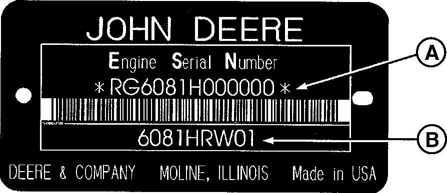
Engine Serial Number Plate Information
IMPORTANT: The engine serial number plate can be easily destroyed. Remove the plate or record the information elsewhere, before “hot tank” cleaning the block.
Engine Serial Number (A)
Each engine has a 13-digit John Deere engine serial number identifying the producing factory, engine model designation, and a 6-digit sequential number. The following is an example:
RG6081H000000
RG Factory code producing engine
6081H Engine model designation
000000 Sequential serial number
Factory Code
RG Waterloo Engine Works
Engine Model Designation
6801H (See ENGINE MODEL DESIGNATION.)
Sequential Number
000000
6-digit sequential number
The engine serial number plate is located either on the right-hand side of engine between the oil filter base and fuel injection pump (viewed from flywheel end) or on the left-hand side of the engine directly above the starter motor.
Engine Application Data (B)
The second line of information on the engine serial number plate identifies the engine/Deere machine or OEM relationship. SeeENGINE APPLICATION CHART later in this group.
A Engine Serial Number B Engine Application Data
Engine Option Code Label
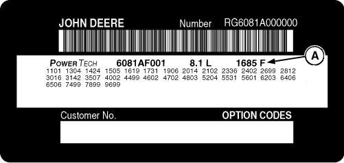
In addition to the serial number plate, later OEM engines have an engine option code label affixed to the rocker arm cover. These codes indicate which of the engine options were installed on your engine at the factory. When in need of parts or service, furnish your authorized servicing dealer or engine distributor with these numbers.
Engine Application Chart (John Deere Agricultural Equipment)
Engine Application Chart (John Deere Construction Equipment)
Engine Application Chart (OEM) (Outside Equipment
CTM86 (06JUL06)