13 minute read
Brought To You By: MyShedPlans

Free 12 x 8 Shed Plan With Illustrations, Blueprints & Step By Step Details
Click Here To Download 12,000 Shed Plans >>
Advertisement
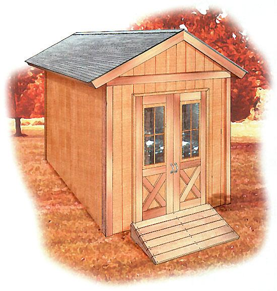
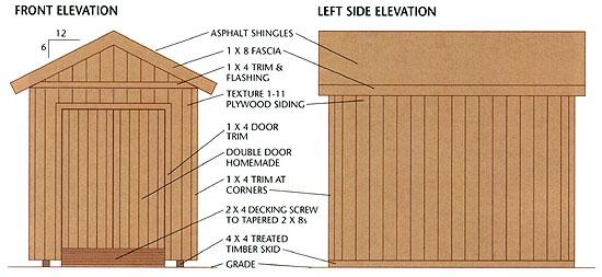
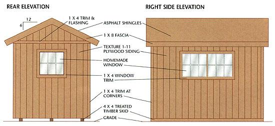
This 8 × 12-ft. shed features a simp le gable roof, double doors, and s ide and rear windows for natural lig hting. With full-hei ght walls and doors , there's ample room for storing large items or creating a comfortable work space. An option al wood ramp helps in moving lawn mowers and other heavy equipment.
The shed's simple construction makes it especially adaptable for different uses. For example, you can easily frame in additional windows—to use the shed as a workshop or potting shed—or omit all of the windows and devote the sp ace entirely to secure storage.
The finish materials for the basic shed also are true to its name: asphalt roof shingles, plywood siding, and simple trim details are appropriately practical for this cl assic outbuilding design. You can purchase prehung doors or build your own using the project plans.
Materials Description Quantity/Size Material Foundation Drainage Compactible material 1.4 cu. yd. gravel 4 × 4 treated Skids 3 @ 12'-0" timbers Floor Framing 2 × 6 pressure Rim joists 2 @ 12'-0" treated 2 × 6 pressure joists 10 @ 8'-0" treated 3/4" tongue-&- Floor 3 sheets, 4 × groove ext.-grade sheathing 8' plywood 3" × 3" × 3" × Joist clip 16-gauge angles 20 galvanized Wall Framing Bottom 2 @ 12'-0", 1 plates @ 8'-0" 2 × 4 4 @ 12'-0", 4 Top plates @ 8'-0" 2 × 4 Studs 40 @ 92 5/8" 2 × 4 2 @ 10'-0'', 2 Headers @ 6'-0" 2 × 6 Header 1 @ 9'-0", 1 @ 1/2" plywood—5" spacers 6'-0" wide Gable Wall Framing Top plates 2 @ 8'-0" 2 × 4 Studs 2 @ 8'-0" 2 × 4 Roof Framing Rafters 22 @ 6'-0" 2 × 6 Metal anchors— rafters 10, with nails Simpson H1 Rafter ties 3 @ 8'-0" 2 × 4 Ridge board 1 @ 14'-0" 2 × 8 Lookouts 1 @ 8'-0" 2 × 6 1 @ 8'-0", 2 @ Subfascia 10'-0'' 2 × 6 Soffit nailers 3 @ 8'-0" 2 × 2 Exterior Finishes Plywood 10 sheets @ 4 5/8" texture 1-11 siding × 9' plywood siding,
2 pieces @ 8 Galvanized—18 Z-flashing ft. gauge Wall & corner trim 10 @ 10'-0" 1 × 4 S4S cedar Fascia 8 @ 8'-0" 1 × 8 S4S cedar Plywood 2 sheets @ 4 × 3/8" cedar or fir soffits 8' plywood Louver with bug Soffit vents 4 @ 4 × 12" screen Flashing (door/window Galvanized—18 trim) 8 linear ft. gauge Roofing Roof 6 sheets @ 4 × 1/2" ext.-grade sheathing 8' plywood Asphalt 250# per square shingles 150 sq. ft. (min.) 15# building paper 150 sq. ft. Metal drip 2 @ 14'-0", 4 edge @ 6'-0" Galvanized metal Roof vents (optional) 2 units Door 3/4 × 4 1/4" 2 @ 8'-0", 1 @ (actual) S4S Frame 6'-0" cedar 2 @ 8'-0", 1 @ Stops 6'-0" 1 × 2 S4S cedar Panel 1 × 6 T&G V-joint material 12 @ 8'-0" S4S cedar Z-brace 4 @ 6'-0" 1 × 6 S4S cedar Construction adhesive 1 tube 2 @ 8'-0", 1 @ Exterior trim 6'-0" 1 × 4 S4S cedar Interior trim 2 @ 8'-0", 1 @ (optional) 6'-0" 1 × 2 S4S cedar Strap hinges 6, with screws Exterior hinges Windows 3/4 × 4 1/4" (actual) S4S cedar Frames 5 @ 6'-0" Mullion 1 @ 3'-0" 2 × 4 S4S cedar Stops 10 @ 6'-0" 1 × 2 S4S cedar
Glazing tape 30 linear ft. Glazing ta pe 3 pieces—field 1/4" clear, Glass measure tempered Window muntins (optional) 3 @ 8'-0" 1 × 1 S4S cedar Exterior trim 5 @ 8'-0" 1 × 4 S4S cedar Interior trim (optional) 5 @ 8'-0" 1 × 2 S4S cedar Ramp (Optional) 2 × 8 pressure Pads 2 @ 6'-0" treated 2 × 8 pressure Stringers 1 @ 8'-0" treated 2 × 4 pressure Decking 7 @ 6'-0" treated Fasteners 16d common nails 16 lbs. 10d common nails 1 lb. 10d galvanized casing nails 1 lb. 8d common nails 1/2 lb. 8d box nails 3 lbs. 8d galvanized box nails 1 1/2 lbs. 8d galvanized finish nails 7 lbs. 3d galvanized box nails 1/4 lb. 7/8" galvanized roofing nails 2 lbs 1 1/2" joist hanger nails 80 nails 1 1/4" wood screws 70 screws 3 1/2" deck screws 12 screws 3" deck screws 50 screws
2 1/2" deck screws 40 screws 1 1/4" deck screws 30 screws Siliconelatex caulk 1 tube


Step A: Build the Foun dation & Floor Frame
1. Excavate the building site an d add a 4" layer of compactible gravel. If desired, add an extension to the base for the optional wood ramp. Tamp the gravel thorough ly, making sure it is flat and level.
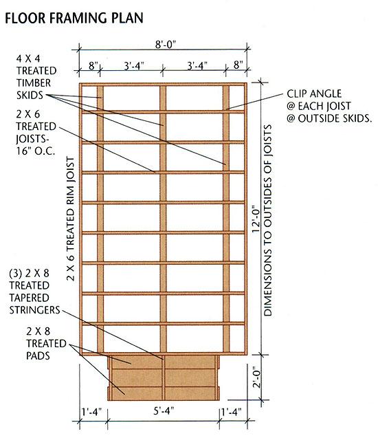
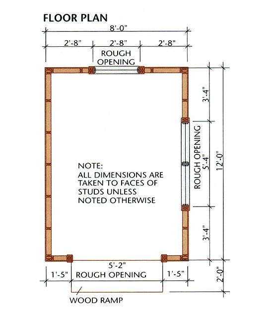
2. Cut three 4 × 4 treated timber skids at 144". Arrange and level the skids on the gravel bed, following the FLOOR FRAMING PLAN.
3. Cut two 2 × 6 rim joists at 144" and ten joists at 93". Mark the joist layout onto the rim joists, following the plan. Assemble frame with 16d galv. common nails; be sure to check each joist for crowning and install it with the crowned edge up.
4. Set the floor frame on top of the skids and measure the diagonals to make sure it's square. Install metal clip angles at each joist along the two outer skids, using 1 1/2" joist hanger nails and 16d galv. common nails, and toenail each joist to the center skid with 16d galv. nails.
5. Install the tongue-and-groove floor sheathing, starting with a full sheet at one corner of the frame. Use 8d galv. nails driven every 6" along the edges and every 12" in the field.
Step B: Frame the Walls
1. Snap chalk lines on th e floor f or the wall plates.
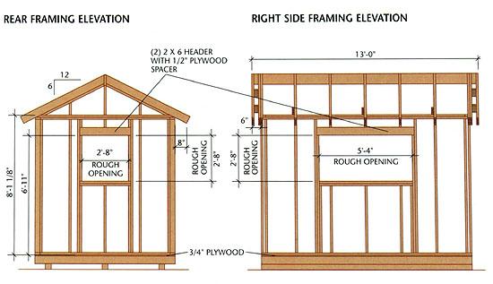
2. Cut the 2 × 4 wall plates: four at 144" for the side walls and four at 89" for the front and back walls.
3. Mark the stud layouts onto the plates following the FLOOR PLAN.
4. Cut twenty-seven studs at 92 5/8", and cut six at 81 1/2" to serve as jack studs.
5. Build three headers with 2 × 6s and 1/2" plywood: one at 65" for the door opening, one at 67" for the right side window, and one at 35" for the rear window.
6. Assemble, raise, and brace the walls one at a time, then add the double top plates.
Step C: Frame the Roof
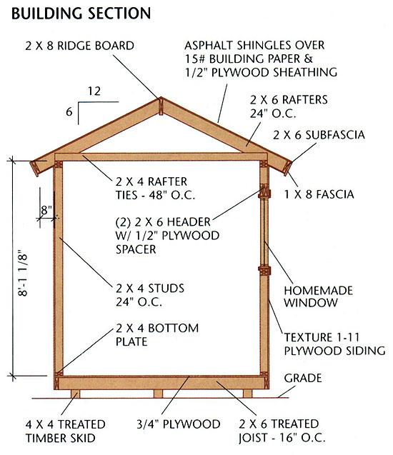
1. Cut two pattern rafters, followi ng the RAFTER TEMPLATE. Test-fit the rafters using a 2 × 8 spacer block, then cut the remaining twelve common rafters. Cut eight rafters for the gable end overhangs—these do not have bird's mouth cuts.
2. Cut the 2 × 8 ridge board at 156" . Draw the rafter layout onto the top plates and ridge board, using 16" on-center spacing. The outsides of the outer common rafters should be 6" from the ends of the ridge board.
3. Install the rafters. Reinforce th e rafter-wall connection with metal anchors—install them on all but the outer common rafters.
4. Cut three 2 × 4 rafter ties at 96", and clip the top outer corners so they won't project above the rafters. Position each tie next to a pair of rafters as shown in the FRAMING ELEVATIONS. Facenail each tie end to the rafter with three 10d nails, then toenail each tie end to the top wall plate with two 8d nails.
5. Cut the gable-wall plates to reach from the ridge to the wall plates. Install the plates with their outside edges flush with the outer common rafters. Cut and install the gable studs, following the FRAMING ELEVATIONS.
Fasten the bottom ends of the common rafters t o the wall plates with metal anchors.
Attach lookouts to four of the overhang rafters, then nail the overhang rafters to the outer common rafters.
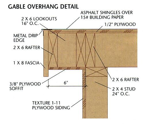
Step D: Build th e Gable Overhangs
1. Cut twelve 2 × 6 lookouts at 3" . Endnail the lookouts to each of the inner overhang rafters, using 16" on-center spacing (see the GABLE OVERHANG DETAIL).
2. Facenail the inner overhang rafters to the outer common rafters with 10d nails.
3. Fasten the outer overhang ra fters to the ridge and lookouts, using 16d nails.
1. Cut and install the 2 × 6 subfa scia along the eaves (see the EAVE DETAIL). Keep the ends flush with the outsides of the overhang rafters, and the bo ttom edges flush with the bottom rafter edges; use 16d nails.
2. Install the 1 × 8 fascia along th e gable overhangs, then along the eaves, holding it 1/2" above the rafters so it will be flush with the sheathing; use 6d galv. finish nails.
3. Install the 1/2" plywood sheathin g, starting at a lower corner of the roof; use 8d box nails driven every 6" along the edges and every 12" in the field of the sheets.
4. Attach metal drip edge along the eaves, then apply 15# building paper over the sheathing. Add dripedge along the gable ends, over the paper.
5. Install the asphalt shingles, starting at the eave edge. If desired, install roof vents.
Install the plywood roof sheathing after installing the fascia. Nail every 6" at the edges and every 12" in the field.
1. Cut twelve 2 × 2 nailers to fit between the rafters, as shown in the EAVE DETAIL. Fasten the naile rs between the rafters with 10d facenails or 8d toenails.
2. Rip the 3/8" plywood soffit panels to fit between the wall framing and the fascia. Fasten the soffits to the rafters with 3d galv. box nails.
3. Cut holes for four soffit vents: locate one vent in each of the two outer rafter bays, along the eave, on both sides of the building. Install the soffit vents.
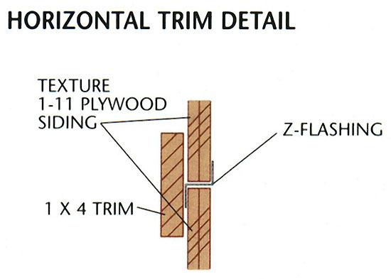
4. Install the plywood siding, using 8d galv. finish nails. Butt the top edges of the siding against the soffits. Don't nail the siding to the rear-window and door headers in this step. At the gable ends, inst all Z-flashing along the top edge of siding, then continue the siding up to the soffits.
Note: Along the side walls, 8-ft. si ding will cover the floor plywood by about 1/2" (this is necessary); if you want the siding to cover the floor framing, use 4 × 9-ft. sheets.
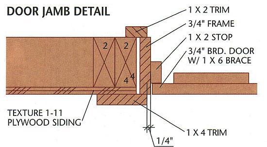
Step G: Build & Install the Doors
1. Cut out the bottom plate from the door opening.
2. Cut the door frame pieces from 3/4" × 4 1/2" (actual dimension) cedar: cut the head jamb at 61 1/4" and the side jambs at 81 7/8". Assemble the frame by screwing th rough the head jamb and into the side jambs with 2 1/2" deck screws.
3. Cut 1 × 2 stops and install them inside the jambs with 1 1/4" deck screws or 3d galv. finish na ils. If the doors will swing out, install the stops 2 1/4" from the outside edges of the frame; if they'll swing in, install the stops 2 1/4" from the inside edges.
4. Install the door frame in the rough opening, using shims and 10d galv. casing nails. Make sure the frame is square and plumb.
5. Cut twelve pieces of 1 × 6 tongue-&-groove boards at 81 3/4". For each door, fit together six boards with their ends flush, then mark the two end boards for trimming so that the total width is 30". Trim the end boards.
7. Install the hinges and hang the door, using shims to set the gaps at the bottom and top of each door.
8. Install flashing above the door, nail-off the siding, then install the 1 × 4 door trim, using 8d galv. finish nails.
Use pairs of tapered shims to plum b and level the door frame in the rough opening.
Assemble the window frames with screws. Add a 2 × 4 mullion in the center of the side window frame.
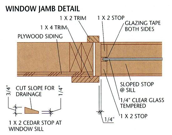
Step H: Build & Install the Windows & Trim
Note: If you've bought prehung windows for the shed, install them following the manufacturer's di rections. To build homemade windows, use the following directions.
2. Install each window frame in its rough opening, using shims and a level to make sure the frame is plumb and level and the jambs are straight. Fasten the frame with 10d galv. casing nails.
3. Cut the 1 × 2 stops. Bevel the outer sill stops as shown in the WINDOW JAMB DETAIL. Attach the inner stops with 6d galv. finish nails. Order the glass to fit.
4. Install the glass and outer stop s, applying glazing tape to the stops on both sides of the glass. Install the 1 × 4 window trim.
5. Install the horizontal 1 × 4 trim as shown in the ELEVATIONS. Fasten the trim with 8d galv. finish nails.
6. Install the 1 × 4 corner trim so that it butts against the horizontal trim and extends to the bottom edges of the siding.
7. Caulk along all trim joints, wh ere trim meets siding, and around the door and window trim.
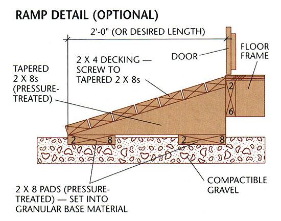
Step I: Build the Ramp (Optional)
Determining the width and length (a nd thus the slope) of the ramp is up to you, but here is th e basic construction procedure:
1. Determine the best slope for th e ramp using boards or plywood set on the ground and the shed fl oor. Mark the ground to represent the end of the ramp.
2. Cut two 2 × 8 pads to the full width of the ramp.
3. Measure the distance from the ground to the shed floor; subtract 2" from that dimension to get the height of the tapered stringers.
4. Use the ground marking to determine the length of the stringers—be sure to account for the 1 1/2" thickness of the decking. Cut the tapered stringers from 2 × 8 lumber: cut one for each end and one for every 16" to 24" in between.
5. Attach the pads to the stringers with 16d galv. nails driven through the bottom faces of the pads and into the stringers.
7. Attach the decking boards to th e supports with 16d galv. nails or 3" deck screws, maintaining a 1/8" gap between boards.
8. Set the ramp in place against th e shed and fasten it by toenailing through the end stringers and top decking board with 3 1/2" deck screws.
Build the ramp with pressure -treated 2 × 8s and 2 × 4s, following the plan's size or building it to a custom size.
Did you enjoyed this plan?
If so, visit MyShedPlans now and download over 12,000 plans and blueprints
This 12 x 8 Shed Plan Is Brought To You By

MyShedPlans
Click Here To Download Over 12,000 Shed Plans >>

Visit MyShedPlans Today And See How Easy It Is To Build Beautiful Sheds With Easy-To-Follow Blueprints!