

Transmission Line & Components
BROADCAST COMMUNICATIONS PRODUCTS & SYSTEMS SINCE 1942
Dielectric helped to pioneer the broadcast age in 1942, and continues to be the world’s most trusted manufacturer and supplier of antennas and RF systems for TV and radio networks.
With more than 75 years in business, Dielectric reliably powers over-the-air operations worldwide. Dielectric is the undisputed leader for high-power North American systems, and continues to gain low-power market share in Asia, South America, and other international regions through its Powerlite series. Mostly anyone who has received TV and FM broadcasts over the air, whether at home or while traveling, has enjoyed that content courtesy of a Dielectric system.
Dielectric's manufacturing operation today focuses on five key areas of expertise:
• HIGH-POWER TV SYSTEMS
• LOW-POWER TV SYSTEMS
• TRANSMISSION LINE AND COMPONENTS
• RADIO ANTENNAS AND COMPONENTS
• RF SYSTEMS (FILTERS AND COMBINERS)
• MONITORING & MAINTENANCE
All five manufacturing areas share common traits, using only the highest quality materials and engineering to develop robust, long-lasting systems. Dielectric products are built for longevity and endurance in the most challenging outdoor conditions.
Dielectric also employs many of today’s brightest RF engineering minds, blending years of expertise with a forward-looking philosophy that embraces software-defined planning and design. Dielectric’s support services extend to consultation across pre-sales, installation and commissioning. Dielectric is also driving unforeseen innovation into the convergence of RF and IP technologies, beginning with its new RFHAWKEYE® monitoring system that will change the way that broadcasters monitor, manage and troubleshoot antenna and RF systems for generations to come. Products contained in this catalog
6,703,984; 6,703,911; 6,677,916; 6,650,300; 6,650,209; 6,617,940; 6,538,529; 6,373,444; 6,320,555; 5,999,145; 5,861,858; 5,455,548; 5,418,545; 5,401,173;
4,988,961; 4,951,013; 4,899,165; 4,723,307; 4,654,962; 4,602,227; 7,084,822; 7,081,860; 7,061,441; 7,034,545; 7,012,574; 6,972,731; 6,972,648; 6,961,027; 6,914,579; 6,441,796; 7,102,589
Additional patents are pending.
General Description
Coaxial Worksheet
EIA Line & Components
digiTLine® & Components
EHTLine® & Components
Unflanged Line & Components
Hangers & Accessories
Power & Efficiency Tables
RECTANGULAR WAVEGUIDE
General Description
Rectangular Waveguide Worksheet Components Accessories
Rectangular

Introduction
Dielectric is the world's largest manufacturer of Rigid Coaxial Transmission Line. Our record of reliable service and superior quality, as well as our ongoing research and development programs, have kept us the leader in our field. Dielectric manufactures rigid coaxial transmission lines in sizes ranging from 7/8" to 12". Outer conducter material is available in aluminum in certain sizes.
More TV and radio stations, utilizing rigid Coax Transmission Line, are on the air with Dielectric.
Features
HIGH CONDUCTIVITY COPPER
Dielectric’s volume allows us to purchase entire mill runs (to our specifications) of high conductivity copper tubing, 95% ICAS/99.04% purity, providing Transmission Line of constant impedance and continuous high power capacity and low insertion loss.
WELDED CONSTRUCTION
All of Dielectric’s factory installed flanges and joints are Tungsten Inert Gas Welded to ensure structural integrity and long life.
EXPANSION COMPENSATION
RF heating of the inner and outer conductors causes differential expansion between the inner and outer which must be compensated for. Dielectric’s constant impedance expansion connector is used to provide this differential expansion. The unique design of this silver plated, watch band spring connector prevents arcing and maintains constant impedance.
INNER CONDUCTOR SUPPORT
Dielectric uses superior low loss PTFE disc type insulators (not pin or rod type supports) for long term reliability and service. Dielectric’s line also utilizes a unique magneform process for insulator support undercuts. With magneforming, undercuts are magnetically formed rather than rolled or welded, allowing the use of a continuous inner conductor with excellent mechanical and electrical characteristics.
HEAVY WALL TUBING
Dielectric uses heavy wall tubing in most miter elbows. In critical locations requiring extraordinary support, such as the bottom elbow on vertical runs, additional reinforcing is added.
VSWR Maximum Limit Values
Selection of Proper Line Section Length
Dielectric’s patented digiTLine is designed to operate at any VHF, UHF or FM channel. Standard lines require selection of a proper length for a given channel to obtain a low VSWR system.
Combining Channels
When combining channels into coaxial lines the power handling capability of the line must be evaluated (see page 6). For standard lines such as EIA , the line section length must also be evaluated. The tables shown are provided for such an evaluation.
Prohibited Channels per Line Length (3 MHz & 1.5 MHz Guard Bands)
Prohibited for 3 MHz Guard Band
Prohibited for 1.5 MHz Guard Band =
Notes:
1. For short transmission line runs, or those feeding a VHF, the flange stackup may be insignificant. Check with manufacturer.
2. A 1.15 VSWR at a single discrete frequency may not be detrimental to a Solid State transmitter, consider that when evaluating field data.
3. For waveguide runs, check with manufacturers.
Recommended Line Lengths
General Specifications
1. GAS STOP
Normally one gas stop is needed at each end of a coax run. Its purpose is to supply a method to stop gas or dry air from entering into an area which does not require pressurization, or when different pressurizations are required.
2. DEHYDRATOR & GASSING KIT
Select the proper size dehydrator based on the size and length of coax run. The gassing kit supplies the connection of the tube and fittings from the dehydrator to the gas stop.
3. STRAIGHT SECTIONS OF RIGID COAXIAL TRANSMISSION LINE
This line is normally supplied in 19 1/2, 19 3/4 or 20 foot lengths. They are bolted end to end with the seal always on the end toward the antenna or tower top. This allows for observation of the condition of the coax contact prior to the installation of the next mating piece. Hardware is always supplied for one end of each component.
4. HORIZONTAL ANCHOR PLATE
These are normally used to anchor the coaxial transmission line to the building. They also permit the user to seal the building from the outside weather.
5. HORIZONTAL SPRING HANGERS (THREE POINT)
These hangers are used to suspend the horizontal run and provide flexibility when warranted by expansion and contraction due to heating and cooling of the line. These are to be spaced 10 ft. apart.
6. LATERAL BRACES
Used to restrict lateral motion of the coax while permitting vertical and horizontal movement. One is normally attached at the bottom of the vertical run.
7. UNEQUAL LEG REINFORCED ELBOWS
It is suggested that unequal leg elbows be used in most places because they provide the maximum amount of support on the inner conductor. Normally they are used at the bottom of the tower, in the elbow complex at the tower top and inside the building.
8. VERTICAL SPRING HANGERS
These hangers support the vertical run of coax and provide the flexibility required when vertical expansion and contractions occur due to thermal temperature changes.
DEHYDRATOR
BUILDING WALL
HORIZONTAL BRIDGE
WALL (HORIZONTAL) ANCHOR PLATE
GAS STOP AND DEHYDRATOR CONNECTION PORT
Minimum Horizontal Run Length vs Height
VERTICAL SPRING HANGER SPACED EVERY 10 FEET
HORIZONTAL SPRING HANGER
Peak Ratings
Tables of power handling and efficiency are shown on pages 29-32. Ratings are based on a temperature rise of 80°C. Where peak power is the limiting factor, it is possible to utilize a more economical size transmission line by increasing the dry air or gas pressure within the line, as long as the average power does not exceed the line rating2. The table below illustrates the ratio of increased peak power in a transmission line with changes of pressures.
STANDARD CONDITIONS
VSWR: 1.0:1
Line Pressure: 0 PSIG
Inner Conductor Temp: 120°C
Ambient Temp: 40°C
Improved Rating with Line Pressure Average Power
Two factors impose limits on transmission line use: temperature and voltage (or power). Average power causes maximum temperature of the line is exceeded, the inner conductor will failure to excessive oxidation.
AVERAGE POWER
A number of conditions affect line temperature and the maximum average power rating of line. Dielectric’s transmission line ratings reflect a maximum inner conductor temperature of 120°C. Other factors such as 40°C ambient at sea level (assumes worst case summer condition for the continental US), zero wind velocity, and unity VSWR are utilized for calculation purposes.
A reduction in ambient temperature or increase in wind velocity causes the power rating to increase. Conversely, an increase in VSWR, sun load, or very high elevation can raise temperatures and lower average power handling.
PEAK RATINGS
Peak voltages and peak power are directly related and can be used interchangeably as a measure of the breakdown limits of the transmission line. Peak voltages must not exceed the ability of the air or the insulators in the line to resist arcing. Laboratory measurements are used to determine voltage breakdown limits. Theoretical calculations can also be used, factoring in allowances for humidity, pressure, surface roughness of conductors, the relationship of inner and outer conductors, the relationship between DC Highpot and RF breakdown at high frequencies. The peak voltage limit is the same value for all frequencies in a given size line.
NTSC
The peak-of-sync (or peak-envelope) power is defined by the RMS amplitude of the carrier during the horizontal and vertical sync periods.
The peak instantaneous power of NTSC, which occurs when the aural and visual peak voltages add in phase, is used to determine the voltage breakdown condition of all components, from the transmitter output to the antenna.
The average power of NTSC is not constant. It depends on the contents of the picture being transmitted. With total blanking, the average visual power is constant and is -2.2 dB below peak-of-sync. The average visual power of NTSC, combined with the aural power are used to calibrate the transmitter from calorimetric measurement of average power. Mathematically, P ave = P sync (APL + A/P sync), where APL is the average picture level and is .6 during blanking, and A/P sync is the ratio of aural to visual peak power, typically .1 (10%) for UHF, and .2 (20%) for VHF.
DTV
For DTV the average power is independent of the content of the image being transmitted; unlike with NTSC, it is a constant value and there is no separate aural carrier to consider. For DTV, the average power will be the significant parameter in ERP, coverage, interference and CNR (Carrier-to-Noise Ratio) calculations.
1 5/8"
3 1/8" 2,180 10
4 1/16 3,685 13
6"-50 ohm 8,513 20 6"-75 ohm 5,550 20
7 3/16" 7,458 23
8 3/16 9,930 27
The average power alone, however, cannot be used to define the size of either the transmitter or passive components (filters, transmission line, antennas), which will be evaluated on peak power or voltage breakdown conditions.
COMBINING CHANNELS (SEE CHART AT LEFT)
When combining channels into one transmission line, both average and peak ratings must be evaluated. In general, for carriers of equal power, the peak power rises as the square of the number of carriers.
Straight Sections Fixed Flange
Transmission line with flanges on both ends. Includes one anchor connector, one O-ring and one hardware kit.
Without Expansion Inner Conductor
Random Lengths Fixed Flange
1 5/8
4 1/16"
50
6 1/8" 675-006 50
6 1/8 677-006 75
7 3/16"
Length: Specified by Customer Approx Weight: Determined by Length (see chart at right)
Without Expansion Compensation
Flanged on both ends. Supplied with anchor connector, O-ring and hardware kit.
90° Mitre Elbow (Equal Leg)
90° elbow, equal length legs. Includes one anchor connector, one O-ring and one hardware kit. Swivel Flanges.
90° Mitre Elbow (Equal Leg)
90° reinforced elbow, one long and one short leg. Includes one anchor connector, one O-ring and one hardware kit. Swivel flanges.
90° Mitre Elbows (Unequal Leg)
45° elbow, one long and one short leg. Includes one anchor connector, one O-ring and one hardware kit. Swivel flanges.
90° Mitre Elbow (Unequal Leg) Reinforced
45° Mitre Elbow (Unequal Leg)
COAXIAL TRANSMISSION LINE EIA
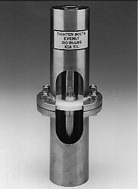
Gas stop for nominal pressure differential. Installs between two flanged line sections. Includes innerconductor connector, one O-ring and complete hardware (long bolts).
Gas Stop
Flange for field installation by soft soldering. Solder, liquid flux, brush, garnet paper and cleaner. Sold separately.
Soft Solder Flange
This table shows cut back for 20' sections.
Anchor connector (inner-conductor connector and insulator).
Note the cut back difference between 50 & 75 ohms and 6 1/8 & 9 3/16. The given dimensions are for cutting back the inner and outer conductor of transmission line onto the end of which a flange is to be installed.
Connector Anchor Insulator
End cap with gas port. Includes O-ring and hardware kit. For temporary closure of transmission line to prevent entrance of moisture. Includes pipe plug.
End Cap
COAXIAL TRANSMISSION LINE EIA
Reducer to smaller line constant impedance. Includes inner conductor connector, O-rings and hardware.
Reducer
Quick Step Reducer to Type "N"
Female Type "N" Connector
Male Type "N" Connector
Cutoff Guide for Outer Conductor
Includes Clamp
O-Ring Buna-"N"
Cutoff Guide for Inner Conductor
Includes Clamp
High Efficiency
High Power Handling
The Leader in Rigid Transmission Line Technology
Before Dielectric’s patented digiTLine® was introduced in 1997, rigid coaxial transmission line was manufactured in 20 ft, 19.75 ft. or 19.5 ft sections. Certain lengths could not be used at specific frequencies as a high VSWR would result. This meant a line used at Channel 22, for example, could not be used at Channel 53. Semiflex cable, while more broadband, is less efficient with lower power handling and a somewhat high overall VSWR.
BROADBAND DESIGN
digiTLine® combines the best features of rigid copper coaxial line and semi-flexible cable. By eliminating the limitations on channel use, digiTLine® can be used at ANY channel. The result is the only BROADBAND rigid line with HIGH POWER HANDLING and HIGH EFFICIENCY.
ADVANCED CONNECTOR
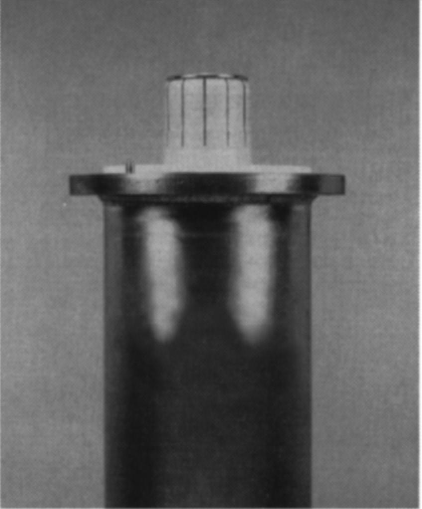
digiTLine®’s advanced patented connector combines Dielectric’s time-proven watchband expansion technology, anchor insulator support, and improvements in materials and manufacturing tolerances to virtually eliminate discontinuities at the flange joint.
HIGH EFFICIENCY & POWER HANDLING
digiTLine® delivers the high efficiency and power handling required for NTSC and DTV transmissions.
Transmission line efficiency is extremely important in order to deliver maximum power to the antenna with minimum loss. Such high efficiencies are only achieved with rigid copper coaxial transmission lines like digiTLine® › Broadband
Many well known Dielectric features (such as high conductivity copper, heavy wall reinforced elbows and heliarc welded EIA flanges) are standard. COMBINES
digiTLine® attenuation and power handling tables are listed on page 13. Examples to evaluate power handling (average and peak) for NTSC, HDTV or combined operation are given in the appendix.
INNER CONDUCTOR SUPPORT
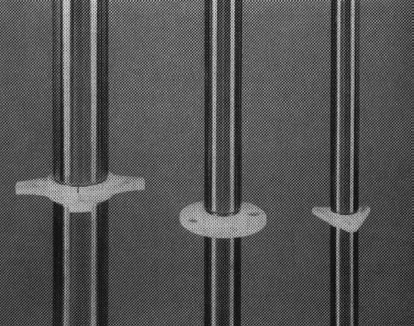
digiTLine® uses Dielectric’s superior low loss PTFE disc type insulators (not pin or rod type supports) for long term reliability and service. digiTLine® also uses Dielectric’s unique magniform process for insulator support undercuts. With magniforming, undercuts are magnetically formed rather than rolled or welded, allowing the use of a continuous inner conductor with excellent mechanical and electrical results.
digiTLine® is also available as EHT (Enhanced Heat Transfer) line—refer to pages 14-15.
AVAILABLE SIZES
digiTLine® is available in 3 1/8”, 4 1/16”, and 6 1/8” (50 and 75 ohm); and 7 3/16” (75 ohm) sizes. digiTLine® is also available in 8 3/16” to channel 52, and 9 3/16” to channel 38.
INSTALLATION & MAINTENANCE
digiTLine® is installed and maintained like standard rigid line.
OTHER STANDARD FEATURES
COMBINES THE
Transmission line with flanges on both ends. Includes expansion connector, O-ring, and hardware kit.
CABLE.
Straight Sections—Fixed Flange With DigitLine® Expansion Connector
90° reinforced elbow, equal leg. Includes one anchor connector, one O-ring and one hardware kit. Swivel flanges.
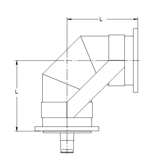
90° Elbow (Equal) Reinforced
90° reinforced elbow, unequal leg. Includes one anchor connector, one O-ring and one hardware kit. Swivel flanges.
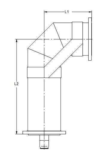
90° Elbow (Unequal) Reinforced
State of the art in coaxial transmission lines!
A revolutionary design and unique manufacturing process allow the inner conductor of our new EHTLine® to run cooler than standard line at the same input power. The average power ratings of this new line are up to 45% higher than standard coaxial line. This allows the use of a smaller EHTLine®, lowering the windload on the tower. EHTLine® is available as EIA or Dielectric broadband digiTLine®. Refer to EIA and digiTLine® sections for specifications not listed here.
6 ¹ / ₈" - 50 OHM POWER HANDLING @ CH38*
k W
HIGHER STANDARD EHTL ineTM
k W
*Conditions: Loss at 0 kw, power at 15 PSIG, 40° C ambient, 120° C inner. For power ratings @ 0 PSIG multiply by 0.885 for 50 ohm and 0.875 for 75 ohm.
› Enhanced Power Handling
› Lower Tower Windloading
› Proven Connector & Inner Support Designs
› Available in All Line Sizes & Types
EHT Power Handling
EHT Power Handling
› High Conductivity Copper
› Excellent VSWR Characteristics
› Low-loss PTFE™ Dielectric Insulators
› Gas Welded Miter Elbows
› Easy Installation
Dielectric’s 50-ohm unflanged hard drawn copper transmission line is designed for unpressurized indoor applications in AM, FM and all VHF television installations. It has excellent VSWR characteristics. It also makes use of PTFE™ disk supports and high conductivity copper. Insulator undercuts are designed with a magneformed relief that maintains a continuous inner conductor for maximum strength and conductivity.* Components are ruggedly and precisely constructed. Miter elbows are made of heavy wall tubing and are welded for utmost strength and reliability. The inner conductor is supported with PTFE™ discs. A complete line of components in 1 5/8, 3 1/8, 4 1/16 and 6 1/8 inch line sizes provides installation versatility for a wide power range.
*1 5/8” uses soldered inner bushings.
General Specifications
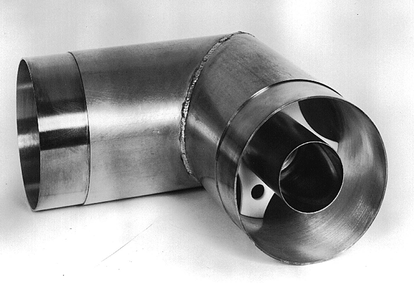
Straight Sections
90° Elbow Equal Leg
90° Elbow Unequal Leg
45° Elbow Unequal Leg
For joining line sections and components. Consists of outer sleeve, inner conductor and two clamps. Coupling, straight, unpressurized. Includes two hose clamps and inner conductor connector.
Unflaged Coupling
Connectors for joining inner conductors.
Unflanged Connectors, Inner Conductor
To flange field cut line. Cannot be pressurized. Supplied with hose clamp only. The dimensions given are for cutting back the inner conductor of transmission line onto which a clamp type flange is to be used.
Mechanical Flange
Supplied with hose clamp.
Reducer, Unflanged to Type "N"
To Type "N" Female
To Type "N" Male
Requires two couplings (not supplied).
Reducer, 50-Ohm Unflanged
All stainless steel band and screw.
Coupling Clamps
Guide for cutting outer conductors in the field.
Cutoff Guide (Outer Conductors)
Guide for cutting inner conductors in the field.
Cutoff Guide (Inner Conductors)
HANGERS & ACCESSORIES
Quality Hangers & Accessories
The materials for all components of hangers and kits are carefully selected to resist deterioration from heat, cold, humidity, or other weather conditions as well as unusual corrosive atmospheric contaminants, such as exist in industrial or coastal areas. Such material as bronze and brass castings and stainless steel springs and hardware are typical.
Single Vertical Expansion
Dual Vertical Expansion
Ceiling Hanger Kit
HANGERS & ACCESSORIES
Single, Fixed
For use with vertical runs under 1000 ft.
Single, Fixed, Heavy Duty Hangers
For use with vertical runs under 1000 ft.
Single Horizontal Three-Point Suspension Hangers
For horizontal suspension of a single line.
Dual Horizontal Three-Point Suspension Hangers
*Indicates free length (No Load) *Indicates free
HANGERS & ACCESSORIES
Supports single line at point of entry through wall. One anchor required on each side of wall. Mounting bolts not supplied.
Dual, Fixed
Supports two lines at point of entry through wall. One anchor required on each side of wall. Mounting bolts not supplied.
Single Horizontal Anchor
Mounts through single hole. Complete with two hose clamps. Used to restrict lateral motion of line while permitting vertical and horizontal movement.
Dual Horizontal Anchor
Lateral Braces
HANGERS & ACCESSORIES
Supports single horizontal line. Two required for dual lines. Mounting bolts not supplied. Rollers accommodate no vertical movement; use 3-point suspension hangers for horizontal runs when length of vertical run or stiffness of line will require vertical as well as horizontal movement of the horizontal run.
Horizontal Roller Assemby
DIM IS ADJUSTABLE & INDICATES MIN.
Single Swivel Hangers
For dual horizontal line runs. Takes care of some horizontal line expansion but permits no vertical movement. Use 3-point suspension hangers for horizontal runs when length of vertical run or stiffness of line will require vertical as well as horizontal movement of the horizontal run.
Dual Swivel Hangers
Insulated Hangers
Available for FM installations onto AM towers. Contact factory for details,
For spring tension charts refer to installation guide.
COAXIAL POWER & EFFICIENCY TABLES
3 1/8" 50-ohm Line (Channels 2-69)
Peak Power Rating (kW) 2,180
Peak Voltage Rating (kV) 10
4 1/16" 50-ohm Line (Channels 2-69)
Peak Power Rating (kW) 3,685
Peak Voltage Rating (kV) 13
*Power handling refers to EIA, digitLine and Ultimate line. Does not apply to EHTLine or EHT/digitLine. Refer to pages 14-15.
Peak Voltage Ratings are based on 4:1 margin of safety to theoretical.
Peak Power Ratings are calculated from peak voltage according to the formula, Ppk – Vpk2/Zo.
To determine the peak power based on the RMS of the peak voltage, divide the listed peak powers by 2.
COAXIAL POWER & EFFICIENCY TABLES
6 1/8" 50-ohm Line (Channels 2-64)
Peak Power Rating (kW) 8,513
Peak Voltage Rating (kV) 20
6 1/8" 75-ohm Line (Channels 2-69)
Peak Power Rating (kW) 5,550
Peak Voltage Rating (kV) 20
*Power handling refers to EIA, digitLine and Ultimate line. Does not apply to EHTLine or EHT/digitLine. Refer to pages 14-15.
Peak Voltage Ratings are based on 4:1 margin of safety to theoretical.
Peak Power Ratings are calculated from peak voltage according to the formula, Ppk – Vpk2/Zo.
To determine the peak power based on the RMS of the peak voltage, divide the listed peak powers by 2.
COAXIAL POWER & EFFICIENCY TABLES
7 3/16" 75-ohm Line (Channels 2-68)
Peak Power Rating (kW) 7,458
Peak Voltage Rating (kV) 23
*Power handling refers to EIA, digiTLine and Ultimate line. Does not apply to EHTLine or EHT/digiTLine. Refer to pages 14-15.
Peak Voltage Ratings are based on 4:1 margin of safety to theoretical.
Peak Power Ratings are calculated from peak voltage according to the formula, Ppk – Vpk2/Zo.
To determine the peak power based on the RMS of the peak voltage, divide the listed peak powers by 2.
8 3/16" 75-ohm Line (Channels 2-52)
Peak Power Rating (kW) 9,930
Peak Voltage Rating (kV) 27
COAXIAL POWER & EFFICIENCY TABLES
9 ³/16" 75-ohm Line (Channels 2-38)
Peak Power Rating (kW) 12,568
Peak Voltage Rating (kV) 30
*Power handling refers to EIA, digitLine and Ultimate line. Does not apply to EHTLine or EHT/digitLine. Refer to pages 14-15.
Peak Voltage Ratings are based on 4:1 margin of safety to theoretical.
Peak Power Ratings are calculated from peak voltage according to the formula, Ppk – Vpk2/Zo.
To determine the peak power based on the RMS of the peak voltage, divide the listed peak powers by 2.
NOTES
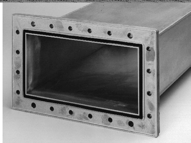
Rectangular Waveguide - pages
32-40 for High Power-High Efficiency UHF Applications
Dielectric has been a major supplier of large high-power waveguide to the microwave industry for the past two decades. This experience has resulted in design, manufacturing, and testing techniques that represent the current state of the art.
THE HIGH POWER ALTERNATIVE
Each form of transmission line has certain features which make its use more advantageous over other types of transmission systems. For UHF television applications, waveguide is particularly attractive because it out performs coaxial transmission line in virtually every area of importance.
Waveguide can handle power levels far in excess of coaxial line ratings.
Because there is no center conductor, waveguide is much less susceptible to shock and vibration during shipping and installation. No center conductor means no insulators and consequently lower loss.
COMPLETE SYSTEMS
Dielectric's product line includes not only individual waveguide components and accessories, but integrated waveguide feed systems as well. Typical feed systems include such items as straight waveguide, sweeps and elbows, mitre bends, twists, switches, couplers, and other components as required for a specific application. In order to provide system compatibility, each component must be manufactured with stringent electrical and mechanical controls.
QUALITY MANUFACTURING
Extreme care is taken to ensure a superior surface finish on the flanges. Flange flatness tolerances do not exceed a total deviation over 5 to 10 mils on a flange face. Deviations exceeding these dimensional tolerances can result in serious arcing at the flange junction in a high power system.
Another unique process welds the flanges in a manner that prevents localized distortion, thus minimizing the periodic VSWR spike that is often characteristic of transmission line systems. Facing the flanges, after welding, ensures accurate parallelism, thus minimizing interface discontinuities.
PRECISION WELDING
Dielectric's waveguide is spayarc argon® welded by unique techniques using precision tooling and fixtures. These techniques eliminate distortion and bow by maintaining uniform stress loading and uniform weld penetration. Consequently, mechanical stability is attained and performance degradation of the guide with aging is eliminated. This is extremely important in long waveguide runs where low VSWR is necessary.
Pressurization Systems
Rectangular waveguide, by the nature of its shape and relatively thin walls, is not conducive to high pressurization; but a slight positive pressure in any transmission line system is necessary to prevent condensation during temperature change.
The guide must not be overpressurized because the walls will be deformed, causing excessive VSWR or a ruptured waveguide window.
LPB-100 Standby System
The LPB-100 is a standby system designed to prevent negative pressure in large volume waveguide runs due to rapid temperature change.
As this rate of change is often much too great for the primary compressor/dehydrator to supply, a pressure switch starts the LPB-100 blower, rapidly supplying a very large volume of dry air through a cylinder containing molecular sieve type desiccant. When the pressure is stabilized, the LPB-100 returns to standby, with its desiccant tower regenerated by a small flow of dry air from the primary compressor/ dehydrator.
Gas Dump
Because of the large volume of air and large surface of the guide, a rapid change of ambient temperature can cause a relatively fast change in the internal pressure. The extra pressure must be bled off rapidly and this is accomplished by the gas dump. The gas dump consists of a precisely weighted cap over an opening in the guide. The cap “pops” off at the maximum pressure for which the guide is designed. When the guide cools, the automatic dehydrator must have sufficient capacity to replace the air in a short time.
The physical parameters of the rectangular waveguide determine the electrical operating characteristics. The dimension of the “broad wall” determines the frequency range of operation.
The dimension of the narrow wall sets the breakdown voltage of the waveguide and therefore the peak power handling capability. It should be noted that as this dimension decreases, transfer efficiency decreases.
The ratio between the broad and narrow wall recommended by the Electronics Industries Association is 2:1. This combination yields a favorable compromise between electrical and mechanical properties and has been utilized extensively by the broadcast industry.
For special applications, Dielectric offers a complete line of rectangular waveguide components including sidewall couplers, directional couplers, folded tees (magic tees), phase shifters, special sweeps and elbows, special waveguide lengths, and half height waveguide.
Rectangular Waveguide Parameters
General Specifications
Operating Temperature Range:
-40 Deg. C to +52 Deg. C
Humidity:
Up to 100% R.H. Including condensate and rain.
Altitude:
0 to 10,000 feet A.M.S.L. S.T.P.
Nominal VSWR (without tuning): 1.1:1 for standard waveguide line run.
Recommended Line Lengths
Section Length vs VSWR
Waveguide, similar to standard rigid coaxial line, requires selection of a proper length for a given channel to obtain a system with low VSWR. The table to the left is provided for proper length selection.
Combining Channels
When combining channels into waveguide both the size and length must be evaluated to obtain low VSWR. The tables at left and below list recommended and prohibited standard line lengths by waveguide size and channel. For specific applications special designs may be available. Contact Dielectric for more information.
Broadband Systems
In specific applications Dielectric has the ability to design broadband systems to combine two or more UHF channels into a single waveguide run. Contact Dielectric for more information.
Prohibited Line Lengths
(size vs. length vs. channel)
WR 1800
14, 15, 19, 20, 25, 26, 30, 31, 36, 37, 42, 43, 48, 49
14, 18, 19, 23, 24, 29, 30, 35, 36, 41, 42, 47, 48 11.95' 17, 18, 22, 23, 28, 29, 33, 34, 39, 40, 45, 46, 51, 52
WR 1500
11.5' 14, 17, 18, 22, 23, 26, 27, 32, 33, 37, 38, 43, 44, 48, 49, 54, 55, 60, 61, 66, 67 11.75' 14, 17, 18, 21, 22, 26, 27, 30, 31, 36, 37, 41, 42, 47, 48, 52, 53, 58, 59, 64, 65 11.95' 16, 17, 20, 21, 25, 26, 30, 31, 35, 36, 40, 41, 45, 46, 51, 52, 57, 58, 62, 63, 68, 69
WR 1150
11.5' 38, 39, 42, 43, 46, 47, 51, 52, 56, 57, 61, 62, 66, 67 11.75' 37, 38, 41, 42, 45, 46, 50, 51, 54, 55, 59, 60, 65, 66 11.95' 40, 41, 44, 45, 49, 50, 53, 54, 58, 59, 63, 64, 68, 69
Minimum Horizontal Run Length vs. Height
Waveguide Size Vertical Run in Feet Minimum Required Horizontal Run Length
WR
1500
WR 1150
Note: 11.75' (141") lengths can be used for multiple channel applications.
System Worksheet
1. GAS BARRIER (500XX-13)
Located before the gas dump section inside the transmitter building. If the elbow complex at the top of the vertical run is coax, an additional Gas Barrier may be required.
2. GAS DUMP SECTION (500XX-18)
Located horizontally with the gas dump hanging downward. Valve is set to protect the guide from high pressure
3. WALL ANCHOR PLATE (500XX-2)
Used to anchor the horizontal run of waveguide to the transmitter building wall. A second one may be used on the interior building wall for aesthetic purposes.
4. RECTANGULAR WAVEGUIDE STRAIGHT SECTIONS (500XX-10)
Bolted together end to end with the seal always facing toward the antenna, allowing observation of the contact surface and seal during installation. Section length dependent upon channel.
5. SWEEP ELBOWS (500XX-8)
Used anywhere a 90° bend is required. One is normally used to connect the bottom of the vertical run to the horizontal run. Where space is limited a mitre elbow may be substituted.
6. TUNER SECTIONS (500XX-21)
As a rule of thumb, one tuner may be placed as close to the building as practical, one at the tower base elbow (vertically is preferred), one at the tower top, just below the cut length and the remainder equally spaced between the top and the bottom tuners in the vertical run.
7. LOWER VERTICAL HANGER LATERAL SUPPORT (500XX-40)
Allows the horizontal run to expand and contract under normal temperature changes. Normally only three of these are required and will be positioned in place of the bottom three (3) vertical spring hangers. The distance from the centerline of the guide to the mounting surface is 2.50" greater than the standard vertical spring hanger.
8. VERTICAL SPRING HANGERS (500XX-41)
These hangers are to be spaced approximately 12 feet apart (one per waveguide section), other than the vertical lateral supports all hangers in the vertical run are the same.
9. TOWER TOP ANCHOR PLATE (500XX-17)
Designed to fix the vertical run to the tower top.
10. HORIZONTAL SPRING HANGERS (500XX-15)
Supports the horizontal run while allowing for vertical movement due to the expansion of the vertical run. One is required for each full length section of waveguide and should be placed near the center of each section.
NOTE: XX INDICATES WAVEGUIDE SIZE
WR 1150=15
WR 1150=14
WR 1150=13
GAS BARRIER A500XX-13
DEHYDRATOR
TUNER SECTION A500XX-21 BUILDING WALL
ANCHOR PLATE A500XX-17
VERTICAL SPRING HANGER A500XX-41 ONE PER W/G
SECTION NOT INCLUDING THE BOTTOM 3 PCS OF W/G.
HORIZONTAL BRIDGE
WALL ANCHOR PLATE A500XX-2
GAS DUMP AND DEHYDRATOR CONNECTION PORT A500XX-18
HORIZONTAL SPRING HANGER A500XX-15
RECTANGULAR WAVEGUIDE STRAIGHT SECTIONS A500XX-10 (SEE NOTE 1)
"E" PLANE MITER ELBOW A500XX-6 OR ("E" PLANE SWEEP ELBOW A500XX-8)
TOWER STRUCTURE
WAVEGUIDE VERTICAL "LATERAL SUPPORT" A500XX-40 BOTTOM 3 POSITIONS
Straight Flanged Waveguide
Note: Hardware kits are ordered separately.
VSWR Tuning Sections
As manufactured, Dielectric Waveguide has a VSWR of 1.1. With on-site tuning, a VSWR of 1.05 is obtainable.
Tuner sections are the same length as standard sections.
The use and quantity of tuning sections required will be determined at time of order.
90° "E" Plane Mitre Bend
Waveguide Size Catalog Number L
WR 1800 50013-6 12"
WR 1500 50014-6 9"
WR 1150 50015-6 9"
90° "E" Plane Sweep Bends
Waveguide Size Catalog Number L R S
90° "H" Plane Mitre Bend
Waveguide Size Catalog Number L
WR 1800 50013-5 18"
WR 1500 50014-5 12"
WR 1150 50015-5 12"
WAVEGUIDE
90° "H" Plane Sweep Bends
Waveguide Size Catalog Number Freq. Range
Waveguide to Coax Transitions
Waveguide Gas Barrier
Waveguide Size Catalog Number C Gas Port Thread
Waveguide Flange Seals
Shorting Plate
Cover Plate—Fiber
WAVEGUIDE ACCESSORIES
Alignment Pins
Gas Dump Section
Waveguide Size Catalog Number
Note: Overall length dictated by Channel. Contact factory.
Anchor Plate—Tower Top
Waveguide Size Catalog Number
WAVEGUIDE ACCESSORIES
Hardware Kits
Waveguide Size Catalog Number
WR 1800
WR 1500
WR 1150
Contains enough hardware for one standard joint.
Wall Anchor Plate
Waveguide Size Catalog Number A
Lifting Plate
Waveguide Size Catalog Number
WAVEGUIDE ACCESSORIES
Horizontal Spring Hangers
Space one per Waveguide length
Waveguide Size Catalog Number
Dimensions are for installed Waveguide.
Vertical Spring Hangers
Waveguide Size Catalog Number
For spring tension charts, refer to installation guide.
WAVEGUIDE ACCESSORIES
Horizontal Fixed Hangers
Material: Strap-aluminum Cushion-neoprene
Finish: Irridite
Fixed Hangers are used before Flex Section on horizontal runs. See tower layout page for Hanger location.
"H" Plane Waveguide Hangers
"E" Plane Waveguide Hangers
DIRECTION OF HORIZONTAL RUN MOVEMENT
*VERTICAL MEDIAN CENTER LINE. BOTTOM (3) HANGERS ONLY. (“D”) SEE INSTALLATION GUIDE. FOR MOUNTING SURFACE DIMENSIONS REFER TO VERTICAL SPRING HANGER.
Vertical Lateral Support
2'
2' LONG THREADED STEEL RODS OF "D" DIAMETER
WR1800 (Channels 14 through 34)
WR1500 (Channels 20 through 56)
WR1150 (Channels 46 through 69)
DEHYDRATORS
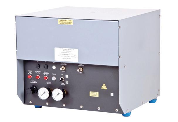
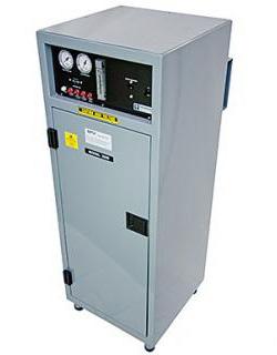
Dielectric’s dehydrator products have been in service in the broadcast, microwave and telephone industries for over 60 years.
Dielectric’s Models 600 and 850 provide a dry air source for a variety of small volume applications (see capacity chart below). These fully automatic, self-contained units are quiet and compact, making them the ideal choice for diverse applications. Adjustable system pressure allows for altitude compensation to assure peak efficiency at any elevation.
The Models 2400/3200 are fully enclosed systems providing quieter operation. All models incorporate five independent alarm circuits that can be monitored individually or as a single C.O. alarm. These units are designed to minimize maintenance time through modularized, field-replaceable subassemblies.
The waveguide dehydrator packages 50015-29, 50014-29 and 50013-29 come complete with everything necessary for a standard installation. The kits include a 2400 dehydrator, excess run alarm, special low-pressure regulator (high pressure output option also available), 20 feet of 3/4" hose and fittings necessary to pressurize your waveguide system.
Air Dryers for Transmission Line
300 TLS 5000' 1650' 850'
66788 (1525) (500) (260)
200C 5000' 1650' 850' 46345(115V) (1525) (500) (260
600C *3500' 2100' 900' 750' 510' 40627(115V) (1070) (640) (275) (230) (155)
850C 5000' 3000' 1500' 1100' 740' 600' 41016 (115V) (1525) (915) (460) (335) (225) (180)
2400 Portable 3500' 2600' 1650' 1350' 49341 (1065) (800) (500) (500)
2400IM 3500' 2600' 2500' 2050' 47141 (1065) (800) (760) (625)
3200 Portable 3250' 2650' 49344 (990) (810)
3200IM 3250' 2650' 47144 (990) (810)
550' 480' (250) (170) (150)
(365) (240) (210) (150) (160) (140)
1100' (700) (500) (550) (460) (335)
1600' 1800' 1500' 1100' (700) (500) (550) (460) (335) 2080' 2340' 1950' 1400' (635) (710) (595) (425) 2080' 2340' 1950' 1400' (635) (710) (595) (425)
MODEL 600
MODEL 2400/3200
ISOLATION > 60 d B
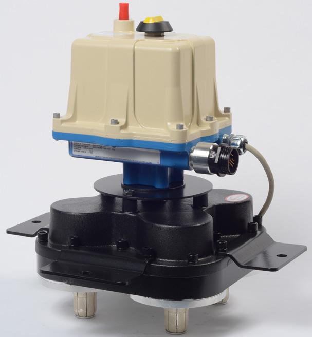
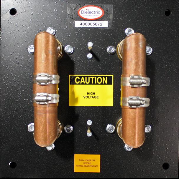
Motorized Switches (60000 Series)
These switches are blade type SPDT or 4 port transfer switches. Sizes include 7/8" through 9 3/16". Switch position is indicated by a mechanical pointer and through auxiliary switches used for readout and interlocking circuits. In the closing mode, the interlock switches do not activate until the RF contacts are ready to accept full power. In the opening mode, the interlock switches open prior to the RF contacts to prevent the breaking of the RF contacts while under power. Manual operation is provided for by a knob. Terminations are standard EIA fixed flanges with non-removable male connectors. Control panels are available.
For more information refer to Dielectric's switch catalog.
Coaxial Patch Panels
• High Isolation
• Low VSWR
• Sizes 1 5/8" through 8 3/16"
• 3, 4 or 7 port Standard
• Custom Types Available
Dielectric patch panels are a low cost reliable solution to multi-connection routing situations. Patch panels are available with or without interlocks. Bolt type (EIA) flanges are standard. Transitions to “no flange” or other line sizes are available. Dielectric can supply panels in custom configurations for special requirements.
For more information, refer to Dielectric's switch catalog.
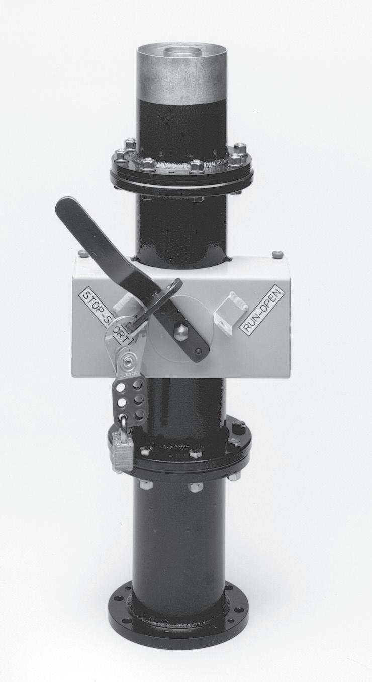
Lockout/Tagout Switch
The RF “Lockout/Tagout” Safety Switch prevents the accidental exposure of workers to RF energy. It acts as an isolation device preventing the flow of RF energy to the transmission line and antenna system. Complies with OSHA rule 1910.147.
Specifications
Isolation > 50 dB
Insertion Loss (in Disengaged Mode)
Characteristic Impedance
Power Rating
RF Connections
Frequency Range
< 0.03 dB @ 100 MHz
50 or 75 Ohms
Equal to Specific Line Size
7/8" to 6 1/8" EIA Flanged
300 KHz to 1 GHz
VSWR (in Disengaged Mode) < 1.05:1.0
RF DIRECTIONAL COUPLERS
1 5/8", 3 1/8", 4 1/6", 6 1/8", 7 3/16", 8 3/16", 9 3/16"
• Low VSWR
• 30 dB Directivity or Greater
• Type N Output
• Field Replaceable Resistor
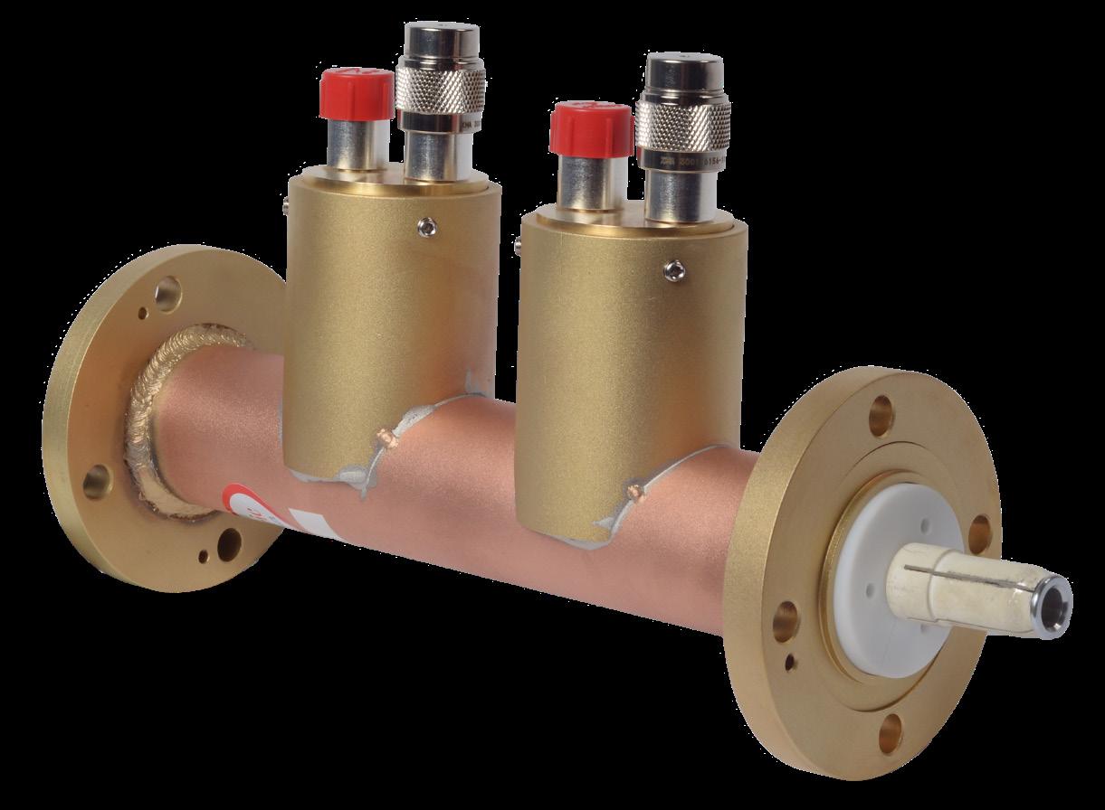
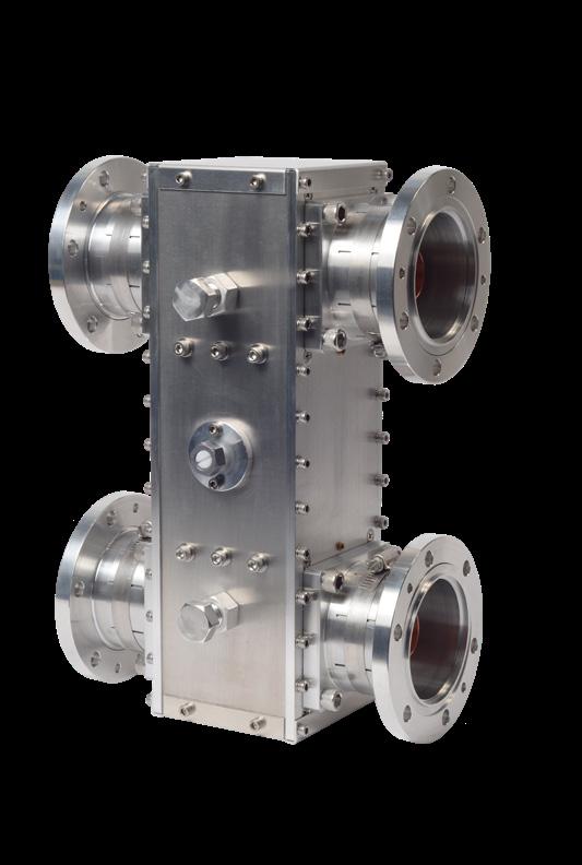
Dielectric VHF/UHF Directional Couplers are designed to couple signals from a transmission line to external monitoring equipment for tuning, operating, and maintaining the station. By installing several couplers in the output transmission line, it is possible to monitor parameters including: VSWR, RF line power, system losses, sideband response, and filter performance.
The directional characteristic of the coupler permits sampling of the transmitter output line without any of the inherent variations in frequency response obtained with non-directional couplers. The voltages obtained with a directional coupler in the line are a sample of either the incident or reflected wave. The directional coupler provides a source impedance to the RF coaxial cable equal to the characteristic impedance of the cable.
These directional couplers are designed for mounting on any section of transmission line with an impedance of 50 or 75 ohms. Coupling is electromagnetic with directivity of 30 dB or better, and is accomplished with a coupling loop inserted into the fields of the main output line. Etched angle and penetration scales on the coupler assembly permit accurate adjustment for calibration of the output voltage at the particular frequency desired. The output is type "N" and at maximum, 2-3 watts. VSWR is 1.03:1 or less.
The coupling loop termination resistor is a high tolerance, fixed composition resistor, which is field replaceable.
Single
Supplied with Hose Clamps.
Dual
Supplied with Hose Clamps.
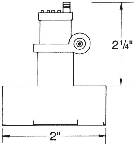
MOUNTING NOTE: A HOLE IS MADE IN OUTER CONDUCTOR TO ACCOMMODATE THE COUPLER.
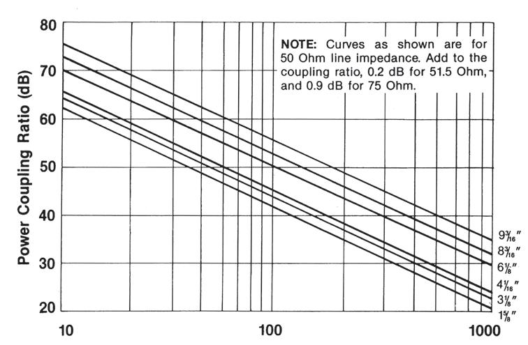
FREQUENCY (MH z )
NOTE: MAXIMUM COUPLING RATIO IS APPROXIMATELY 50 d B GREATER THAN THE MINIMUM VALUES SHOWN.
› Enhanced local user interface
› Transmission system monitor for VSWR, pressure, overpowering, and temperature
› Forward and reverse remote power sensors measure power at directional couplers
Scout-out elevated VSWR before it causes problems
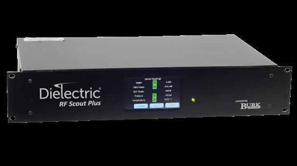
The Dielectric RF Scout Plus monitors RF transmission system VSWR and forward power to aid in detecting VSWR problems as they develop. In many cases, this will allow the transmitter operator to remedy transmission system contributors to elevated VSWR before they affect operations. The unit continuously monitors forward and reflected power, and displays the values. It can hold one month of half-hour data and up to 100 alarms. The system can also be configured to monitor transmission line pressure and temperature. User-settable options include warning and alarm levels, enable/disable interlock trip for each monitoring function, and a VSWR alarm strikeout number.
The RF Scout Plus offer a high degree of flexibility in monitoring and communications capabilities. The unit’s status is available to local operators via a 4.3” touch panel, and to remote operators through an Ethernet interface with HTTP (web page).
The RF Scout monitoring system comprises a rack-mountable unit with two power sensors and their associated 25’ cables, along with a dual directional coupler with factory pre-set coupling values consistent with the forward power level. The coupler sections are designed for the various line sizes available. The RF Scout Plus may also be supplied without the coupling section for systems that already have the appropriate couplers in place. Pressure transducers and thermocouples can be supplied separately.
The RF Scout Plus with PlusConnect provides a seamless link to Burk Technology ARC Plus remote monitoring and control systems, bringing RF Scout Plus-monitored and -controlled parameters aboard the ARC Plus. A single serial connection to the ARC Plus network reduces installation time and saves the expense of adding remote control capacity. If you already have an ARC Plus system controlling your transmitter, you don’t have to rewire IP connectivity between the RF Scout Plus and the ARC Plus, eliminating the need to run new wires or cable from the RF Scout to the remote control. Just add the RF Scout with the PlusConnect to your ARC Plus network.
Communications are secure thanks to an encrypted digital signature sent with each packet.
Specifications
Processor
Display
Display Functions
Senor Inputs
RF Senors: Standard
RF Senors: Low Power
Transmitter Interlock
Remote Interface Functions Output (24 VDC)
Input (24 VDC)
Embedded PLC Controller
3", Back lit Touch Panel
VSWR Value Forward Power Reflective Power Line Pressure Temperature
User Set-Up Menu for all options/parameters
(2) 0 to 5 VDC for RF Power
(1) 0 to 5 VDC for Pressure (1) Thermocouple
Dielectric P/N 97730, 50 to 800 MHz, True Average Power, 50 Ohm, Type N, 1.0 W Max
Dielectric P/N 11000005351, 50 to 800 MHz, True Average Power, 50 Ohm, Type N, 100 mW Max
SPDT, Dry contacts, Latching Relay (250VAC, 2.5amps)
TX Interlock trip VSWR Alarm
Forward Power Alarm
Pressure Alarm
Interlock Reset
Lan Port 10/100 base T Ethernet, FTP Server, Web
Power 100-240 VAC, 60/50 Hz
Dimensions (cm)
2 Rack Unit,19"(48.2)W x 10"(25.4)D x 3.5"(8.9)H
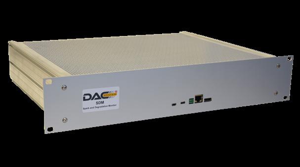
› Continuous remote real-time, time-domain system measurement and recording at full power
› Detects, locates and warns of VSWR changes or arcing in the transmission line
› Compatible with any modulation scheme: ATSC 1.0, ATSC 3.0, DVBT, etc.
RFHAWKEYE® is the RF Monitoring & Control System of the future...available today.
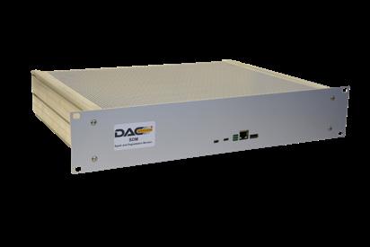
RFHAWKEYE® is the first IP-connected system that delivers real-time data to effectively monitor your transmission line, the unsung workhorse of a broadcast system. Undetected degradation of this vital component can be devastating, leading to extensive damage and time off-air.

Specifications
Parameter
RF Connector CU
RF Connector CU
Spec
2 x N - Female / 50 ohm
2 x N - Female / 50 ohm
RF Connector PU Chanel 14, 470-700 MHz
Frequency Range > 1 dB
Detection of Return Loss < - 45 dB
Smallest Detectable Reflection +/-8 in
Accuracy of Location of Return Loss/VSWR Variation or Arching
Power Consumption CU
Power Consumption PU
Material CU
Dimension CU
Dimension PU
Weight CU
Passive Component
30 Watt
100-240 VAC, 60/50 Hz
Rigid Line: Copper; Flange: Brass
Length 15 in
19" sub-rack - 1HU / H: 43.8 mm x W: 483 x D: 220 mm
7.7 - 15.4 lbs (varies with line size)
Weight PU 6 lbs
Environmental Working Temperature
Safety PU
LAN Interface
Power Supply
Out-of-Band Emission
Arc Detection
32° F - 113° F / 0° C to +45° C
EN60950-1
RJ-45/Ethernet/IP Interface
2 x AC 90...264V, 47...63Hz-IEC
Compliant with FCC § 73.622 (h), < -110 dBc
100% of arc or arc bursts longer than 100 s
Return Loss/VSWR CU > 35 dB / < 1.036:1.0
Distance CU to PU 21 ft
Remotely switch 1-2 RF transmitters via the web!
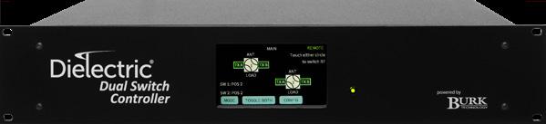
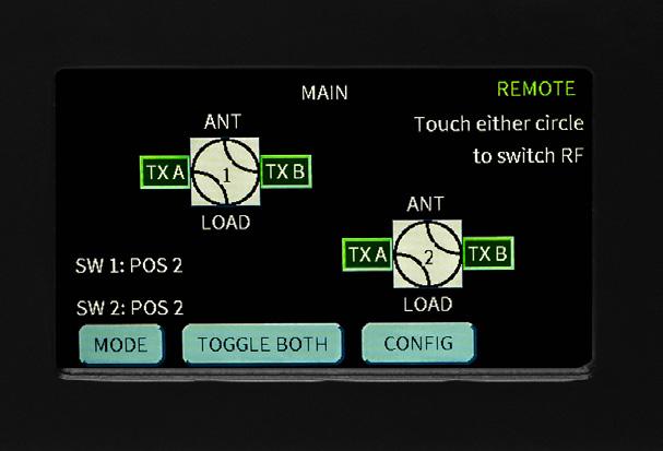
• Control of one or two RF transfer switches (3- or 4-port; coaxial or waveguide).
• Local touch screen, discrete remote-control connections, integral web page or SNMP, in addition to a lockout mode for control of the switch.
• Status monitoring from the front panel color touch screen or any of the remote interfaces.
• User-defined switch port labels that are easily configured via the built-in web page.
• Selectable 12 or 24 VDC switch command voltages.
• Transmitter interlocks with user-defined delay between disengaging the interlocks and initiating a switch command.
• Load interlock input with user-defined association of interlock with specific switch port.
• Burk Plus-X protocol included to allow easy integration of the switch controller with Burk remote-control systems.
• Amphenol 19 pin circular connectors for fast interconnection to switches using standard Dielectric switch cables.
Specifications
Parameter
5.25” (3RU) X 19” x 11” (133mm x 482mm x 279mm)
AC Power Requirements 110-240 VAC/50-60 Hz
AC Power Consumption (Controller Only) 40W
Ambient Temperature, Operating 32°F (0°C) to 122°F (50°C)
Storage Temperature -4°F (-20°C) to 158°F (70°C)
Storage/Operating Humidity
non-condensing


TRUSTED FOR DECADES. READY FOR TOMORROW.
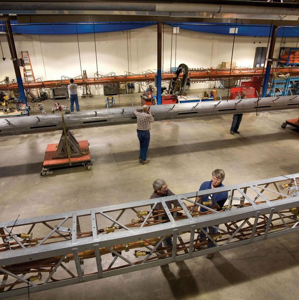
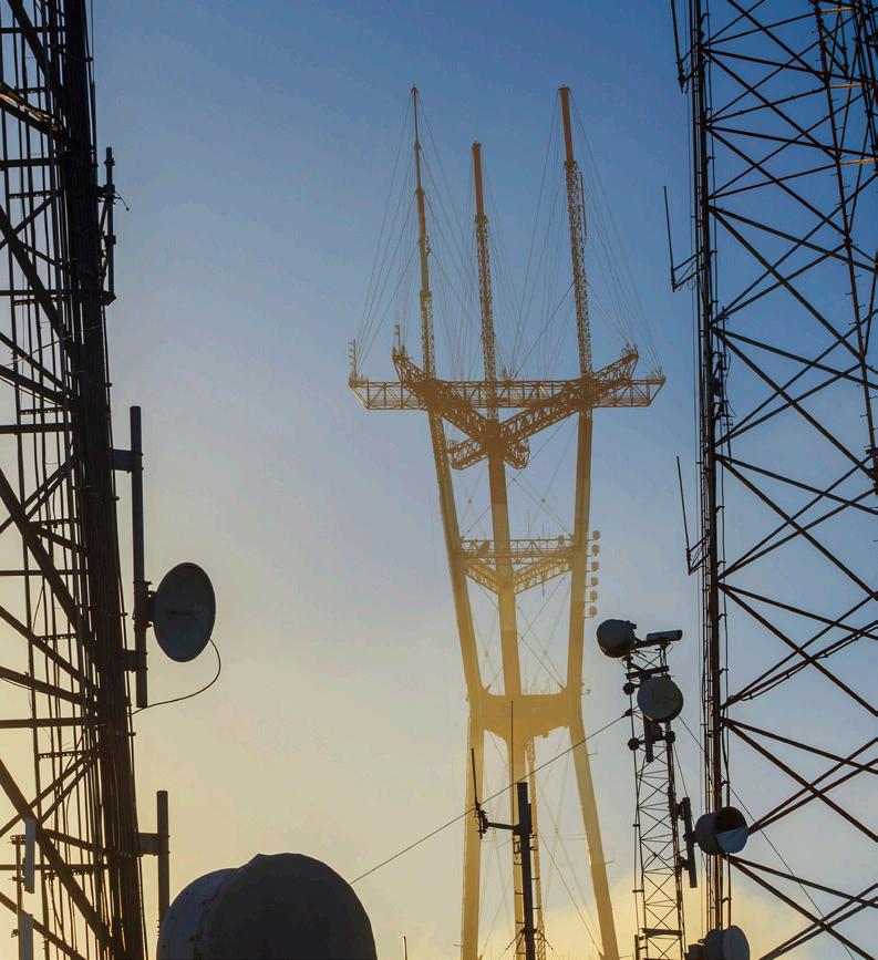
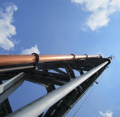
Dielectric has been a leading innovator throughout the history of broadcasting, with more than 100 patents in RF transmission technology since our founding in 1942. Today we are the world leader in the engineering, design and manufacturing of complete broadcast systems. Most recently, Dielectric has led the transition to digital TV in the Americas.
Our engineers bring hundreds of years of combined experience, working on more than 10,000 antennas, to meet your customized needs for the future. Whatever new technologies emerge, there’s a good chance they’ll start here at Dielectric world headquarters in Maine, USA.



Dielectric products are represented in 90 countries around the world. With the rapid expansion of communications, Dielectric is positioned to service the broadcast needs of small & large stations, DTV, FM & specialty RF systems, complete systems and components.
PAPUA NEW GUINEA Specifications subject to change without notice.
AUSTRIA
NORTH AMERICA EUROPE
› BELIZE
CANADA
COSTA RICA
DOMINICAN REPUBLIC
EL SALVADOR
GREENLAND
› ARGENTINA › BRAZIL
CHILE
VENEZUELA › GUATEMALA › MEXICO › NICARAGUA › PUERTO RICO › UNITED STATES
PERU
COLOMBIA SOUTH AMERICA › ECUADOR
FRANCE
GERMANY
GREECE
ICELAND
IRELAND
ITALY
MALTA
POLAND
PORTUGAL
ROMANIA
RUSSIA
SPAIN
SWEDEN
SWITZERLAND
ASIA
ABU DHABI
CHINA
GUAM
HONG KONG
INDIA
INDONESIA
ISRAEL
JAPAN
JORDAN
KOREA
KUWAIT
LEBANON
MALAYSIA
MONGOLIA
NEPAL › OMAN
PAKISTAN › PHILIPPINES › QATAR
SAIPAN › SAUDI ARABIA
SINGAPORE › SRI LANKA
SYRIA
TAIWAN
THAILAND
VIETNAM
OCEANIA AFRICA
› ANGOLA
BENIN
BOTSWANA
CHAD
EGYPT › ETHIOPIA
GHANA
LIBERIA › MADAGASCAR › MALI
› MAURITANIA
› MAURITIUS › MOROCCO
› NIGERIA › SAO TOME › SOUTH AFRICA › TOGO › UGANDA › ZAMBIA › ZIMBABWE
YEMEN › AUSTRALIA › NEW ZEALAND