

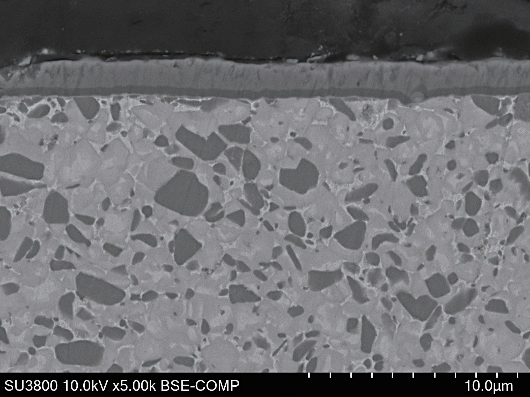
Highly Adhesive Coating Layer
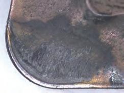
Substrate

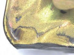
Smooth Cutting Edge Treatment
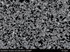

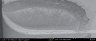
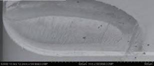
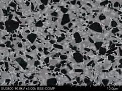
Distinguishing from Carbide Grades (example)
Chipbreaker Selection
D Negative type
Emphasis on Chip Control When chips are long Sharp Edge When chattering, burrs or poor machined surface occurs

fine finishing

D Positive type


Emphasis on High E ciency For high-speed / high-feed applications


When rake face wear is the main damage When adhesion is the main damage
Strong Edge When chipping or breakage occurs


Emphasis on Chip Control When chips are long Strong Edge When chipping or breakage occurs
Edge When chattering, burrs or poor machined surface occurs LB type

type GU type For fine finishing LU type

Chipbreaker Application Range


Wear Resistance Through External Continuous Turning (Steel)
1.5x
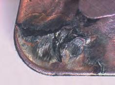
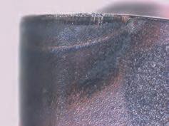
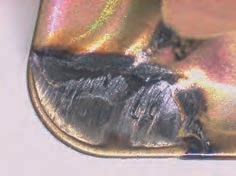
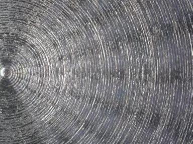
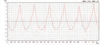
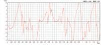
Comparison of Machined Surfaces in Continuous Facing (Steel)
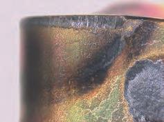
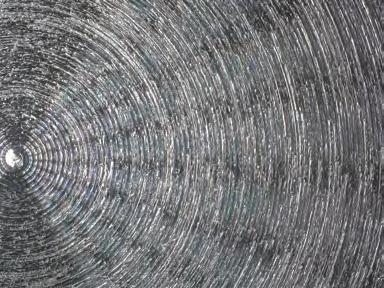
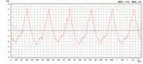
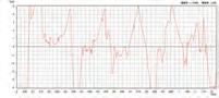
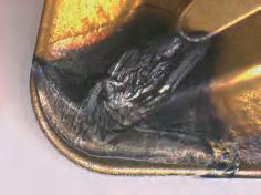
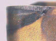
When flank wear is the main form of damage, wear resistance is higher compared to conventional grades and competitors’ grades Surface finish
Fracture Resistance Through Interrupted External Turning (Steel)
Significantly improved fracture resistance compared to conventional grades and competitors’ grades
Number of times impact can be sustained before breakage (each corner) 0 1,000 2,000 3,000 4,000 5,000 6,000 7,000 8,000 9,000
T2100Z
Fracture resistance competitor’s grade or more 3 x
Conventional Grade
Competitor's Grade B
Work Material: Insert:
Cutting Conditions: SCM435 Continuous External Turning CNMG120408 vc = 250m/min f = 0.25mm/rev ap = 1.5mm Wet


Triangular type Negative Inserts / M-class


80° Diamond type Positive Inserts / M-class


55° Diamond type Positive Inserts / G-class


55° Diamond type Positive Inserts / M-class


Triangular type Positive Inserts / M-class


Square type Positive Inserts / M-class (Without Hole)

Triangular type Positive Inserts / M-class (Without Hole)

Application Examples
SCM420H Shaft
Fracture suppressed for stable machining compared to competitor's coated cermet
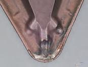
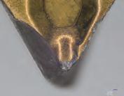
Tool: DNMG150408N-FE (T2100Z) Continuous turning
Cutting Conditions: vc = 350m/min f = 0.2-0.5mm/rev ap = 0.2-0.8mm
SCM420H Shaft SCM420H Automotive ComponentS53C Hub
Flank wear suppressed compared to competitor’s coated cermet
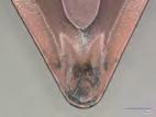
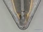
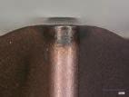
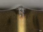
Tool: DNMG150408N-SE (T2100Z) Continuous turning
Cutting Conditions: vc = 260m/min f = 0.1-0.2mm/rev ap = 0.33mm
SPHD Frame
Stable machining and flank wear suppressed compared to coated carbide (P20)
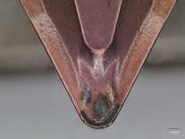
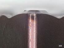
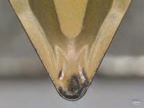
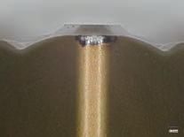
Flank wear suppressed compared to conventional coated cermet
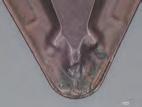
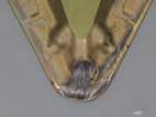
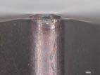
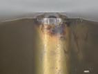
Tool: DNMG150408N-FE (T2100Z) Continuous turning
Cutting Conditions: vc = 350m/min f = 0.2-0.3mm/rev ap = 0.2-1.0mm
Stable and 1.1x longer tool life compared to conventional coated cermet (P30)
of Workpieces
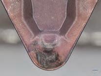
Tool: DNMG150408N-FL (T2100Z) Continuous turning
Cutting Conditions: vc = 300m/min f = 0.3mm/rev ap = 0.15mm
SPHD Frame
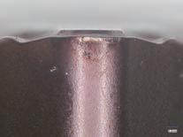
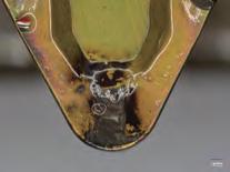
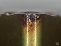
Flank wear suppressed compared to conventional coated cermet
¢ Recommended Cutting Conditions
Mild Steel (SS400, etc.)
Low Carbon Steel
Low-alloy Steel (S10C, SCM415, etc.)
High Carbon Steel
High-alloy Steel (S45C, SCM440H, etc.)
¢ Characteristic Values