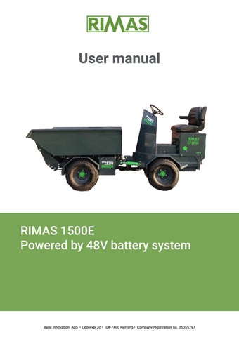

User manual
RIMAS 1500E
Powered
The right to make changes to technical specifications without prior notice is reserved.
Version: 2026/2
1. Introduction
1.1 Preface
We thank you for purchasing a RIMAS machine and trust that it will meet your needs and expectations.
By purchasing this machine, you have acquired a product that has undergone a comprehensive development process based on practical experience from users such as cemeteries, housing associations, landscaping contractors, and similar professional operators.
This user manual has been prepared with the purpose of helping you achieve optimum performance and maximum benefit from your investment.


Important
Read this user manual carefully and keep it readily available at all times for quick reference in case of doubt. Particular attention must be given to the safety requirements, which must be read and understood prior to commissioning. If you require advice regarding your RIMAS loader (hereinafter referred to as the machine), you are welcome to contact the manufacturer.
The manufacturer provides a 1-year warranty against manufacturing defects. This warranty does not cover normal wear and tear, nor damage resulting from overloading or improper use of the machine. Please note that the warranty becomes void if modifications are made to the machine’s construction or if additional equipment is installed without prior approval from the manufacturer.
1.2 Description
The RIMAS machine is a compact, versatile machine designed for transport tasks at construction sites, cemeteries, parks, and similar environments. As standard, the machine is equipped with continuously variable drive, articulated steering, and 2- or 4-wheel drive.
With its robust construction, wide tires, and ergonomic operator’s station, the machine is well suited for operation on grass, uneven or sloped terrain, and in confined spaces. The machine is fitted with a heavy-duty tipping body operated hydraulically.
The rated payload of the machine is approximately 1,500 kg, depending on the additional equipment installed.
2. Transport and handling instructions
If the machine is transported on, for example, a low-loader trailer, swap body container, or car trailer, it must be driven onto the platform. Lifting the machine onto the platform using a forklift or crane is prohibited. Please note that the machine’s unladen weight is approximately 850 kg, depending on the additional equipment installed.
The machine must be securely fastened to the platform using suitable securing equipment capable of restraining the machine under all foreseeable transport conditions.
Under normal transport conditions, the use of transport packaging is not required.
3. Assembly instructions
The machine is tested and ready for operation upon delivery from the manufacturer.
As a precaution, perform a visual inspection for any transport damage and carefully test essential functions such as brakes, lights, steering, etc., at initial start-up.
4. Operating instructions
4.1 Machine construction
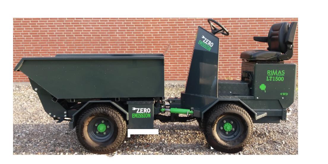
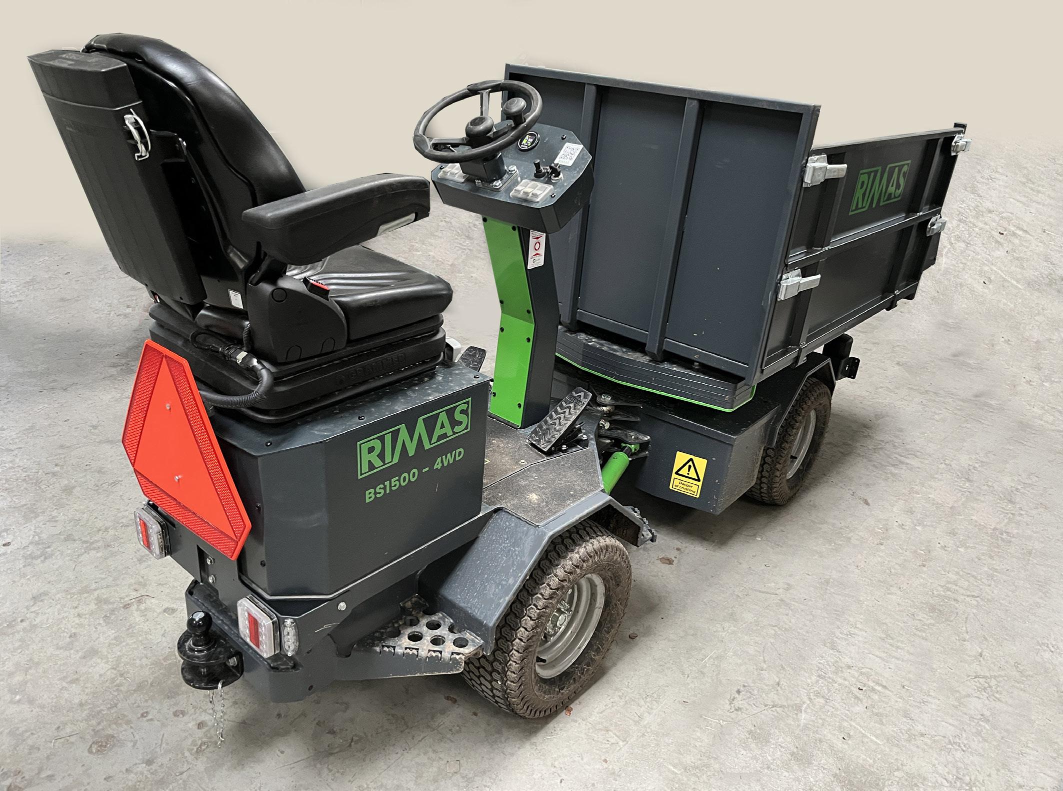
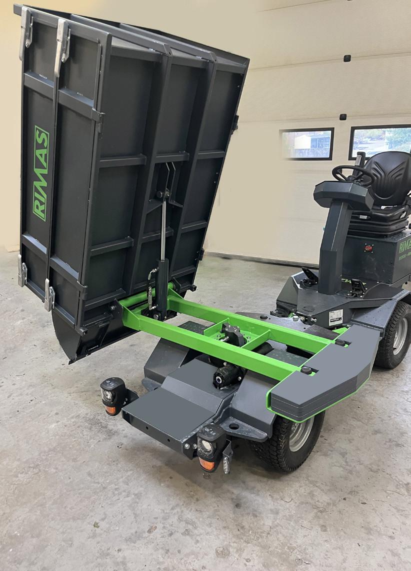
The machine is fundamentally designed to be simple, robust, user-friendly, and to provide easy access to service points. Its principal components and control devices are illustrated in the exploded drawings below.
Minor deviations may occur due to individual customizations and ongoing product development.
4.2 Safety requirements and description of use
General guidelines for the use of the RIMAS machine
The machine has been developed and designed with a strong focus on maximum safety and user-friendly operation. However, certain general guidelines for use must always be observed. It is the responsibility of the operator to exercise due care and consideration for the surroundings during operation of the machine.
General restrictions:
• The operator must be authorized to operate the machine in accordance with applicable local legislation.
• The operator must have read the user manual or received thorough instruction in the operation of the machine prior to commissioning.
• The user manual must always be available to the operator and stored on the machine. If the user manual is lost, a replacement may be obtained from the manufacturer.
• The machine must not be operated by any person who is physically or mentally unfit to operate it safely. It is the responsibility of both the operator and the responsible supervisor to assess this.
• Under no circumstances may the machine be operated by persons under the influence of alcohol, narcotics, sedative medication, or similar substances.
Acceleration
The machine starts smoothly and features continuously variable, gradual acceleration.
Intended use
The machine is designed for transport of materials on the tipping body or for operation with permanently mounted attachments.
If the machine is registered for road use, the maximum payload will be stated on the side of the tipping body.
During operation, a safe distance must be maintained from persons, animals, and property.
If the machine is loaded to a significant height, stability may be reduced. Careful assessment must be made of how the center of gravity has been affected by the load, and driving must be performed with caution accordingly.
The maximum payload of the machine is 1,500 kg. Overloading is strictly prohibited, as it may cause damage to the articulated steering and other components, resulting in risk of failure during continued operation.
Normal operation
Under normal operation, the operator must remain seated in the operator’s seat while driving. Standing while operating the machine is not permitted.
Only one person may be present on the machine during operation.

Warning
The machine’s hydraulically operated tipping body must only be raised on level ground If the machine is positioned on a side slope, there is a risk of overturning. Never tip the body on soft or unstable ground, as this may cause one of the wheels to sink during tipping, creating a serious risk of the machine overturning.
Important
When leaving the operator’s station, the ignition must be switched off. The parking brake engages automatically.
Important
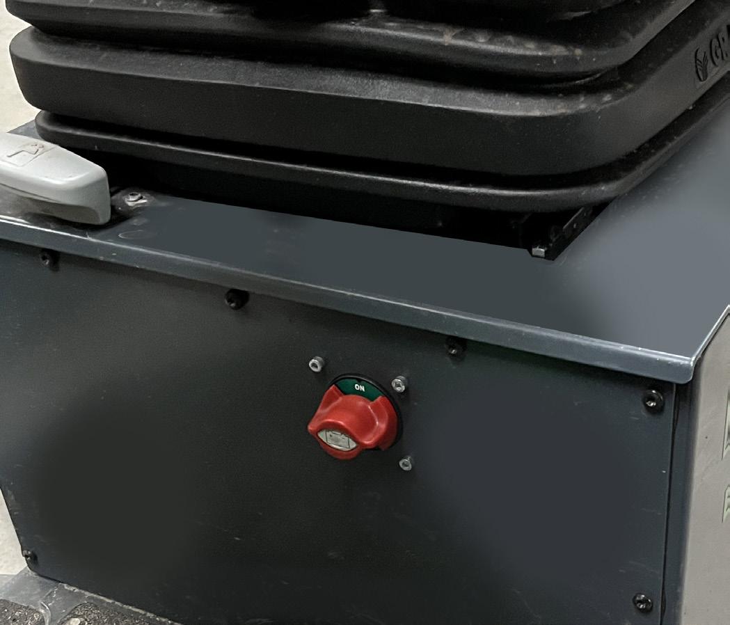
In the event of fire in the machine, activate the emergency stop and leave the machine immediately. If possible, switch off the main switch.
Operation on slopes and inclines
Speed must be adapted to prevailing conditions.
Reduced speed must be maintained when cornering, when passing through narrow areas, and when operating on slopes or soft ground.
Warning
Operation on sloping terrain may result in overturning or rearward tipping. The machine must never be operated on slopes exceeding 20°. Reference is made to the operating instructions for individual attachments, as certain attachments may further reduce the permissible slope angle. When operating on inclines steeper than 20°, there is a risk that the machine may stall and begin to roll backward or overturn.
Warning – Hazard at the articulation joint and moving parts

Warning
Never enter the area around the articulated joint unless the machine has been completely stopped. Never position yourself beneath suspended attachments. Attachments must be fully lowered before leaving the machine. If the machine is left with a raised attachment, the attachment may gradually lower over time.
Warning – Hazard during maintenance and inspection
Warning
Always stop the machine before commencing maintenance or inspection of the machine or its attachments. Activate the main switch, if possible. Appropriate personal protective equipment (PPE) must be worn during service and maintenance work.
Warning labels on the machine


Warning Crushing hazard
Keep a safe distance from persons
Fixed guards
Fixed guards and other protective covers must be securely fastened during operation. Any damaged guards or protective covers must be replaced immediately.
Important
For first-time users, the owner of the machine must provide thorough instruction in the operation of the machine, including a complete review of this user manual.
Particular attention must be given to the safety regulations.
Furthermore, the owner must ensure that the user does not operate the machine in areas with confined spaces, slopes, sharp turns, unstable ground conditions, or terrain that is muddy or slippery, etc.
This restriction applies until the user has obtained sufficient experience and familiarity with the operation of the machine.
Lighting
During normal operation, the operator must ensure that sufficient lighting is available in the working area so that obstacles are not obscured by darkness.
Steering
The steering system is hydraulic and is activated when the machine is started and an operator is seated in the operator’s seat.
In the event of hydraulic pump failure, steering remains possible; however, the steering wheel will require increased effort to turn.
Hydraulic components are protected by guards and are accessible only to authorized service personnel.
Permanently mounted attachments
If the machine is operated with permanently mounted attachments from other manufacturers, the companying operating instructions for such attachments must be strictly followed. Failure to comply may result in risk to the operator and persons in the vicinity of the working area, as well as damage to the machine.
Speed and slopes/inclines
Speed must be adapted to prevailing conditions. Reduced speed must be maintained when cornering and when passing through narrow areas. Operation on sloping surfaces may result in overturning. The machine must not be operated on surfaces with a cross slope exceeding 15% relative to the direction of travel.
When operating on sloped floors, ensure that the surface is sufficiently clean to prevent the machines wheels from slipping on greasy or slippery surfaces.
Maximum incline in the direction of travel: Approx. 30% over a distance of 0.5 m
Approx. 20% over a distance of 1–2 m
Approx. 15% over a distance of 3–5 m
When operating on steeper inclines and with a full load, there is a risk that the machine may stall and begin to roll backward.
Moving parts
Extreme caution must be exercised around the articulation point and during tipping of the tipping body to avoid crushing hazards.
A safe distance must always be maintained from moving parts during operation.
Hydraulic system
The machine is equipped with a hydraulic system.
The hydraulic filter must be replaced every 2,000 operating hours. Hydraulic oil should be replaced every 1,000 operating hours and at least every two years. Specified hydraulic oil: Panolin HLP Synth E32 – 9 L
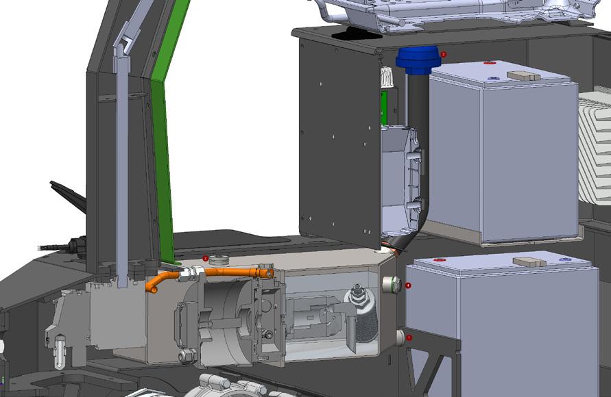

Hydraulic System – Oil Change
• The oil change is carried out by draining the oil by loosening the drain plug (1) on the hydraulic tank or by extracting the oil from the top plug (2) on the tank.
• Once the oil has been drained, ensure that the tank is clean and free from dirt and debris.
• Reinstall the drain plug and fill with new oil via the filling point (3).
• Reinstall the top plug and filling cap once the oil has been filled.
Drained oil must be disposed of in accordance with local regulations.
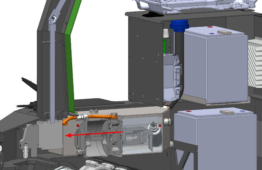
Hydraulic System – Replacement of Oil Filter
• The oil filter is replaced by loosening and removing the pump and motor (1), lifting the motor and pump upward, and then replacing the return filter (2).
• When reinstalling the motor and pump after filter replace ment, the pump must be sealed against the tank flange using liquid gasket compound.
The used oil filter must be disposed of in accordance with local regulations.
Warning
Hydraulic systems operate under pressure. Troubleshooting for possible leaks must not be carried out without protection of hands and eyes. Wear gloves and safety goggles. In unfortunate cases, small leaks may result in jets of such high pressure that bodily injury may occur.
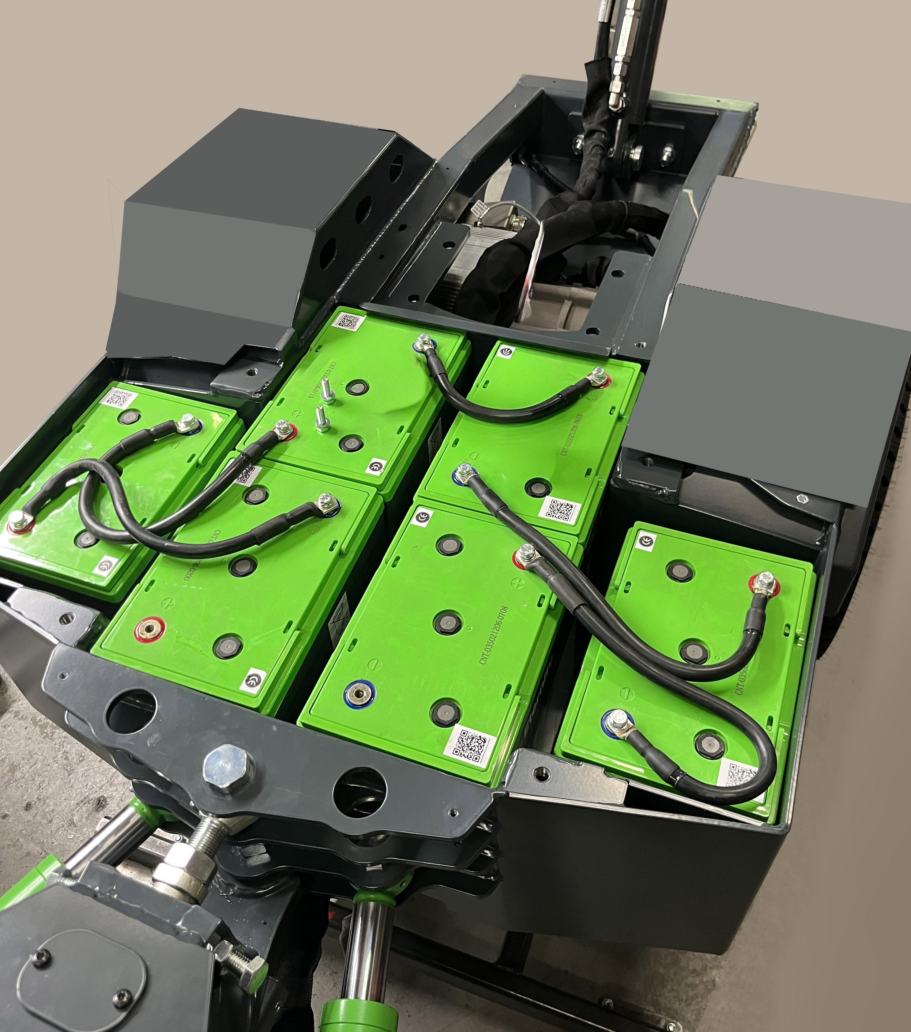
Battery Covering / Securing
Cover plates and securing brackets on the batteries must remain in place during operation in order to prevent possible ejection of electrolyte in the event of the machine overturning. Battery compartments and electronic compartments should only be opened by service personnel and only when the main switch has been activated.
Maintenance
During maintenance of the machine, e.g. lubrication, the machine must be stopped and the main switch activated to prevent risk of personal injury.
Vibrations
Vibrations from the motor are considered insignificant and without danger to the operator of the machine, as the seat absorbs the majority of these.
4.3 Commissioning
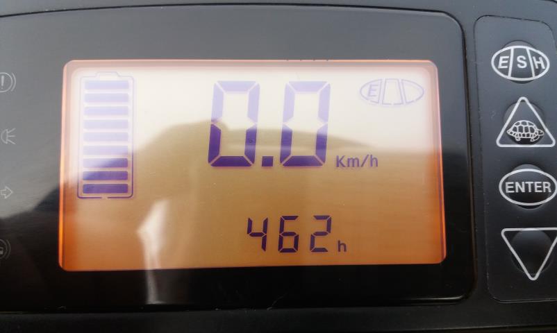
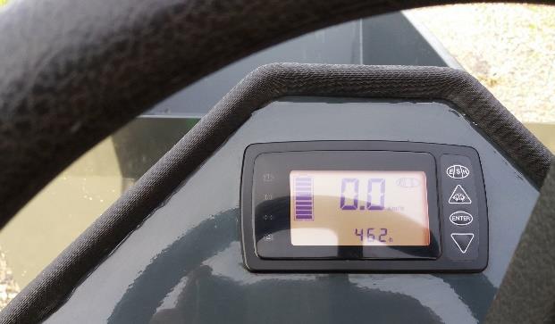
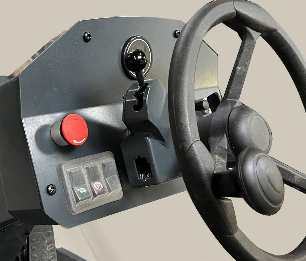
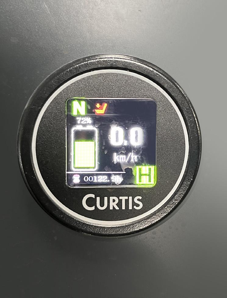
Instrument panel
The instrument displays the following:
• Battery level
• Speed
• Hour meter
• “Turtle” button (reduced speed)
Multi-function display
Located in front of the steering wheel.
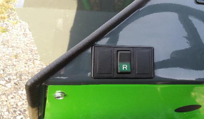
Direction control
Push button located to the left of the steering wheel.
• Button pressed forward: Forward driving
• Button pressed backward (R): Reverse driving
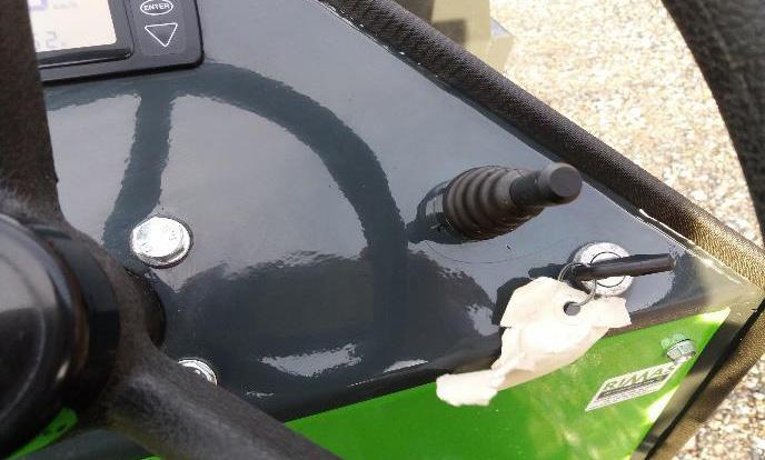
Tipping operation
Joystick mounted to the right of the steering wheel.
• Joystick moved forward: The tipping body is raised
• Joystick moved backward: The tipping body is lowered
Start-up of the machine
Before operating the machine, check the tire pressure and ensure that the battery is fully charged and that no active alarms are displayed.
Start the machine by turning the ignition key to the first position. This activates the relays for the electric motors. Two clicks will be heard, and the machine is ready for operation.
4.4 Driving operation
Drive
In order to operate the machine, the start-up procedure must have been completed.
The foot pedal controls forward and reverse travel
When the accelerator pedal is released, the machine decelerates to a stop over approximately 3 meters. Once the machine has come to a complete stop, a holding brake (stop/go) is automatically activated. This is released when the accelerator pedal is pressed again.
Two types of service brakes are used: regenerative braking and electromagnetic braking.
• Regenerative braking operates by using the electric motor as a brake when the accelerator pedal is released, instead of providing drive power.
• Electromagnetic braking operates via the brake pedal. When activated, the electromagnetic brake is engaged and the vehicle is brought to an immediate stop.
Stopping
When the foot pedal is released, the machine brakes as described above. When the machine is stationary, the parking brake is activated automatically. See above regarding the foot pedal.
Loading
The permissible gross vehicle weight of the machine must not be exceeded. The load must be evenly distributed across the entire tipping body. Loading must be carried out in such a way that there is no risk of the load falling off during driving or braking.
Extending parts of the load must be marked so that they are clearly visible at all times. If clay or moist soil is transported, a thin layer of gravel may advantageously be spread on the bottom of the tipping body to prevent the load from sticking during unloading.
Unloading/tipping
Important
The tipping body must not be raised if the machine is positioned on a side slope or if the load is stuck to the tipping body. The machine must remain completely stationary during tipping, and driving must not resume until the tipping body has been fully lowered. Failure to comply with the above guidelines entails a significant risk of the machine overturning.
Unloading may be commenced when the machine is positioned on level and firm ground. This is done by moving the joystick lever forward. During unloading, be aware that the tipping body is emptied during the upward movement, as adhering material may cause a shift in the center of gravity and reduced stability of the vehicle.
Emergency stop
To stop the machine completely, turn the ignition switch to “O”. This stops the machines hydraulic pump and disconnects all functions.
The machine is equipped with an emergency stop located on the front panel below the steering wheel. In addition, a main switch is mounted on the seat base, which disconnects the batteries.
Battery charging
The battery charger is a processor-controlled charger built into the machine.
Charging is initiated when the supplied charging cable is connected and a grounded 220 V AC power supply is provided.
Charging should take place in a ventilated area where no open flames, welding operations, or similar activities occur.
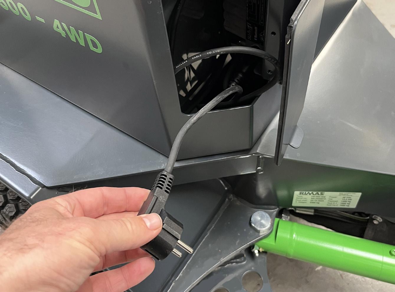
The QR code refers to the manufacturer’s manual. See also the appendix to this manual.
4.5 Technical data
Motor
2 x 5,5 kw
Transmission 2- or 4-wheel drive with continuously variable adjustment
Forward 0–12 km/h
Speed
Brakes
Steering system
Electrical system
Hydraulic system
Tire dimension
Tire pressure
Unladen weight
Reverse 0–12 km/h
Regenerative and electromagnetic brake
Automatic parking brake with ‘hill hold’
Hydraulic with 90° steering angle
Voltage 48 V
Current 217 A
Tank capacity 9 l
Recommended hydraulic oil Panolin HLP synth E32 9L
48v 2,2kw hydraulic station
20 × 10.00 – 10” – 6 ply turf tires
23 × 8.50 – 12” – 6 ply industrial tires (option)
Normal operation
20 × 10.00 – 10” 30 psi
23 × 8.50 – 12” 50 psi
Approx. 850 kg
5. Maintenance instructions
5.1 General
A prerequisite for the machine to function satisfactorily is that daily and periodic inspections are carried out.
The service life of the machine and operation without downtime depend on proper maintenance. As the machine is an electric vehicle, maintenance requirements are minimal.
The following is a summary of checks, inspections, and lubrication intervals. However, it should be noted that operating conditions determine the intervals and not solely the recommendations below.
In case of doubt, always contact the local dealer or the manufacturer.
When using a high-pressure washer for cleaning, do not spray directly at electrical components.
5.2 Running-in period
As the machine is an electric machine, no running-in period is required.
5.3 Maintenance
Weekly inspection points
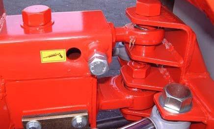
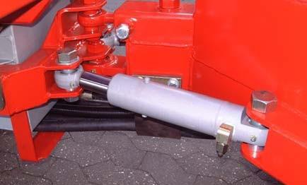
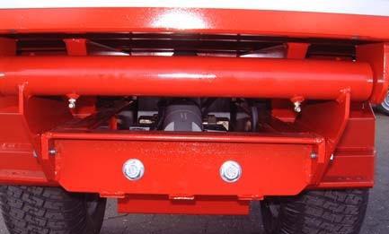
All grease nipples in the articulation joint must be lubricated with multi-purpose grease.
Grease nipple
Grease nipple
Grease nipple
Grease nipple
Grease nipple
The grease nipples at the pivot point of the tipping body must be lubricated with multi-purpose grease.
Check that the bolts (M16) located on both sides are sufficiently tightened.
Annual inspection
The machine is electronically controlled, and energy is supplied by batteries. It is recommended that an annual inspection of the drivetrain be carried out by the local dealer or the manufacturer.
Faults and towing
In the event of a malfunction, an error code can be read on the display. Contact the manufacturer for information and guidance.
If the machine stops unintentionally, this may interrupt the machine’s steering system. Wait a moment and reconnect the switch. This will reboot the controls. If the machine still does not start, contact the manufacturer.
If it becomes necessary to move the machine during a fault condition, the brake(s) must be released. This is done by pulling the bracket on the brake toward the center and securing it in this position. The machine can then be pushed or towed carefully at low speed.
Spare parts
Contact the nearest dealer or the manufacturer directly. Be prepared to provide: Model, year of manufacture, and spare part number.
Note
Always use original spare parts; otherwise, the warranty will become void. It is too late to claim warranty after the repair has been carried out.
Disposal of the machine
When the machine is to be scrapped, this must be done in accordance with local waste disposal regulations.
The batteries must always be delivered to an approved recycling facility. The hydraulic oil must be drained and disposed of properly.
The remainder of the machine may be handled as normal scrap.
6. Warranty
6.1 Warranty, service and claims
A 1-year warranty is provided from the date of purchase against manufacturing defects.
• This warranty does not cover normal wear and tear or if the machine is subjected to overloading.
• The warranty does not cover damage caused by circumstances beyond the manufacturer’s control, including, but not limited to, falling objects, lightning strikes, water, fire, smoke, or other force majeure events.
• The warranty becomes void if modifications are made to the machine’s construction or if equipment or attachments not approved by the manufacturer are used.
• The warranty becomes void if non-original spare parts are used.
• The warranty becomes void if service intervals are not observed.
• It is a condition for the acceptance of warranty claims that maintenance has been carried out in accordance with the guidelines in this user manual. Such maintenance is not covered by the warranty.
• It is a condition for the acceptance of warranty claims that direct contact is made with the manufacturer or one of its authorized dealers before any repair work is commenced.
• A warranty repair carried out by a non-authorized dealer without prior agreement with the manufacturer will not be accepted.
• The manufacturer may, at its discretion, repair or replace defective components covered by the warranty. The warranty on such replaced or repaired parts shall not extend beyond the original 1-year warranty period.
• The manufacturer continuously develops its products; therefore, specifications, equipment, etc., may be changed without notice. This does not entitle the customer to an upgrade of the machine during the warranty period.
• The warranty covers materials and labor in accordance with the manufacturer’s guidelines.
6.2 EU Declaration of conformity
EC Declaration of Conformity

Balle Innovation. Cedervej 2c, 7400 Herning Tel. +45 72 16 17 55 www.rimas.dk
EC Declaration of Conformity
The undersigned, representing Balle Innovation, Cedervej 2c, 7400 Herning Hereby declares that:
Machine: Rimas BS 1500e
Type: BS-000-002 SN-XXXXXXX (Serial number)
Complies with:
Directives 2006/42/EC
DS 116.2.1:2011
Machinery Directive Annex B.
Machinery safety - danger areas, safety distances
DS 116.2.2:2017 Safety of machinery - safety devices
DS 116.2.3:2017
DS 116.1:2018
Machinery safety - ergonomics
Machinery safety - Basic concepts and principles
Herning. Date: 1.12-2023

QUASAR Gel Batteries
Installation & Operating Guide
Safety Instructions
Carefully read this manual in all its parts upon receipt of Eternity Technologies QUASAR Gel Batteries.
Lead-acid QUASAR Gel Batteries are components of a system and although they are low maintenance, they require suitable precautions and behavioural norms to guarantee safe working conditions and to ensure maximum performance of the battery during its entire life. The Installation, Operation and Maintenance instruction manual supplies the necessary instructions for the correct care, handling, installation, use and maintenance of Eternity Technologies QUASAR Gel Batteries.
The non-compliance with the instructions given herein may cause injury to personnel and damage to equipment as well as poor operation and performance of the battery. Any repairs made without authorisation may render the warranty void.
Store this manual in close proximity to the batteries at all times and ensure it is accessible to the relevant personnel.
Observe the following precautions at all times
Observe the operating instructions - work on the battery should be carried out by qualified personnel only.
Exposed metal parts of the battery carry a voltage and are electrically live with the risk of short circuits.
Avoid any electrostatic charge; before starting work on the battery, first discharge any possible electricity from yourself by touching an earth-connected part; repeat this action occasionally until work is complete.
Use protective equipment, such as protective clothing, rubber gloves and goggles.
Use insulated tools.
DO NOT place or drop metal objects on top of the battery.
DO NOT wear rings or bracelets.
Remove any articles of clothing with metal parts that might come into contact with the battery terminals.
DO NOT smoke and DO NOT use open flames or create electric sparks.
Take all precaution when using the main supply.
Make sure that the first aid kits and fire extinguishers are easily accessible.
Used batteries contain recyclable materials. They must not be disposed with household waste but as a special waste. Methods of return and recycling must conform to the regulations in operation at the site where battery is located. If in doubt please contact Eternity Technologies.
1. Delivery, unpacking and storage
Unpack the batteries as soon as they are delivered. Verify that the equipment has been delivered in good condition. Any damage must be reported immediately to the carrier and the damaged items retained for inspection by the carrier’s representative.
If the battery cannot be immediately installed, store it in a dry, cool and clean place.
Do not expose the battery to direct sunlight, to avoid any damage to containers and lids.
During the storage time, the open circuit volrage (OCV) must periodically be checked.
Cells with OCV below 2.15 Vpc must be recharged using an approved charger and VRLA profile.
The OCV of a fully charged battery should result between 2.20-2.22 Vpc.
Recommended storage time for QUASAR Gel cells is 2 months @ 30°C and 3 months @ 20°C.
Failure to observe the above conditions may result in a greatly reduced capacity and service life or in permanent damage to the cells.
2. Installation & Handling
WARNING
The cells are already charged when delivered and should be unpacked with care. Avoid short circuiting terminals of opposite polarity.
The cells are fitted with a Gas Release Valve, please do not remove this valve. The valve is designed to release air from the cell when the pressure builds up to a pre-defined level during charge or discharge. The valve prevents air entering the cell and acts as a fire barrier to the inside of the cell.
Before installing the cells, clean all parts. Remove the short circuit protectors from the terminal posts and discard.
When lifting the cells off the pallet ensure that the cells are adequately secured on all four side to prevent cells from falling over.
Motive power batteries are heavy, so adequate mechanical handling systems should be used. Cells that are lifted using mechanical equipment should be lifted with both terminals. Ensure that the lifting equipment does not short out the battery terminals.
Anti corrosive terminal grease is applied to the terminals to prevent corrosion of the brass insert in the terminal. It is recommended to apply more anti corrosive grease to the terminals if required before fitting the connectors and bolts. Ensure that the cell polarities are lined up correctly before connecting the cells. Connecting the same polarity terminals will cause a short.
Bolts must be tightened to a torque of 23Nm +/- 2Nm. The connectors should be well anchored and sufficiently long to prevent pulling on the battery terminals. The cells must be accessible to facilitate voltage readings.
Before fitting the battery to the vehicle make sure the top of the battery is clean and dry.
Batteries must be kept upright when lifting. Provided in the battery tray (container) are holes into which lifting hooks should be located. Ensure that the battery is located in its correct position on the vehicle and secure any restraining devices.
3. Applications
The QUASAR Gel cells are maintenance free and are the ideal battery technology for certain motive power applications. However, it’s important to ensure the batteries are cleaned periodically as a build-up of grim on the top of the cells can lead to the gas release valve becoming blocked and malfunctioning.
4. Charging
As the cells only release a very small amount of Hydrogen release gas during charging, a dedicated charging room is not required although it is advisable that the charging room / area complies with DIN EN 50272-3.
A full charge should be carried out after every discharge. We advise a minimum of 8 hour charge for a battery taken to a depth of discharge of 70% when charging at standard rates = up to 20A/100Ah.
High-rate charging
Maximum charging currents should be 30A/100Ah. The duration of the charge will depend on the charger manufacturers profile.
Temperature controlled charging is required. The charger should reduce the power output / switch off if the temperature reaches 45°C to allow time for the battery to cool.
IUI profiles are commonly used in VRLA traction charging profiles. It’s important to limit the max voltage for the first two phases to 2.35V
All battery covers on the application should be open when charging to avoid any gas build ups. Do not open or tamper with the gas release valves at any point.
An equalization charge is to be carried out once per quarter to avoid capacity drop and prolong battery life.
The charging and equalization profiles must be approved by Eternity Technologies. Please contact us for any clarification.
NOTE – Constant overcharging of QUASAR Gel products will lead to ‘drying out’ of the cell and ultimately early failure of the battery.
Opportunity Charging
QUASAR Gel batteries can be opportunity charged. Opportunity charging should only take place when the battery is between 3070% SOC. Frequent charging at higher states of charge will lead to overheating and early failure of the battery.
For fast charging, between 20 - 30A/100Ah - The charging and equalization profiles must be approved by Eternity Technologies. Please contact us for any clarification.
5. Operation / Discharge
The QUASAR Gel cells are maintenance free so the valves should not be removed at any point unless instructed to by Eternity Technologies. The cells are ideal for use in storage areas of food, chemicals and pharmaceutical products.
It is recommended that the battery is not discharged beyond 70% of nominal capacity. Frequent deep discharges beyond 70% depth of discharge will lead to early failure of the battery. When the battery has been discharged it should be recharged as soon as possible on the appropriate charger.
A discharge of more than 80% DOD is classed as an abuse cycle and will have a considerable effect on the residual capacity of the battery. This can be avoided by setting the Battery Discharge Indicator (BDI) to a VRLA profile. This can also be clarified by the battery Battery Monitoring Unit BMU data.
QUASAR Gel cells should only be used in light to normal duty applications and for a maximum of 6 times per week. Adequate rest periods should be given to the battery to allow it cool after each cycle.
The recommended operating temperature range for the battery should be between +5 - +35°C. Operating outside of these temperatures will lead to early failure of the battery.
Battery in Service
The QUASAR Gel cells are maintenance free. Never remove the valves or top up with water.
Ensure the cells are clean and dry and remove any liquids present at the base of the battery tray with the drainage tube or pump.
Lifting facilities on battery trays and racks should be examined periodically for corrosion or other deterioration. Do not lift damaged trays as there is a danger of collapse. If the battery is in two units, these should be kept together when charging.
If excessive corrosion or other deterioration becomes evident in any part of the battery it should be reported to Eternity Technologies. Check bolted connections on the battery for tightness and ensure that they are clean.
Inspect battery cable insulation and battery charging connectors for wear and damage to insulation and burning of contacts. Refurbish or replace as necessary.
Keep all terminal connections smeared with an approved anticorrosive grease.
Keep a record of the battery voltage and individual cell voltage on a monthly basis.
• Daily Ensure the battery is charged after use.
• Weekly
Inspect the battery for any signs of dirt, especially around the valve area. Clean the battery if necessary. Any damage should be reported to a qualified technician / the local sales office.
• Quarterly
Perform a full recharge of the battery. After charging, allow a minimum of 5 hours of rest time before taking measurements. Record the following parameters:
- Total battery voltage
- Individual cell voltages
If there are significant discrepancies compared to previous records or noticeable differences between cells, contact Aftersales Service immediately for inspection and repair.
Temperature
The nominal operating temperature for the battery is 30 °C. Temperatures above this will shorten the battery’s lifespan, while lower temperatures will reduce its available capacity.
Operation at the maximum temperature limit of 45 °C is not permitted.
Battery out of Service
If a battery is to be taken out of service for a time, or if a new charged battery cannot be put into service immediately, it should be given a charge and stored in a cool dry place.
Disconnect detachable connectors.
Every 2-3 months, give the battery a charge.
If a vehicle is used at irregular intervals the battery should be given a charge every month and the battery disconnected from the vehicle during its idle periods. Before putting back into service, charge the battery.
7. Disposal of old batteries
Careless disposal of a battery can harm the environment and can be dangerous to the public. Always dispose of spent batteries to an authorised, licensed dealer. Do not attempt to open or dismantle a battery or cell.
The British Standards Institute have published a ‘Code of Practice for Safe Operation of Traction Batteries’ – BS 6287:1982 which is available online.
Additional information
For any further information on Eternity QUASAR Gel batteries, please contact:
Eternity Technologies FZ-LLC
Al Hamra / Al Jazeera PO Box 35102
Ras Al Khaimah U.A.E
Phone + 971 72 433 535
Fax + 971 72 433 536
Web www.eternitytechnologies.com
Charging profile
IU Charging
IUI Charging
I = min. 12% C₅ max. 18% C₅
U = 2.4 V per cell
I1 = min. 12% C₅ max. 18% C₅
U = 2.35 V per cell
I 2 = 1.5 % C₅ for max. 4 hours
Self discharge at different temperatures
Capacity vs. temperature
Storage: Determine the state of charge
Relation between charging, voltage and temperature
Electrical Specifications
C5 Capacity Voltage
80% DOD Voltage Cutoff Self Discharge
Charge Temperature
Discharge Temperature** Storage
Less than 3% per month (20°C/68°F)
Min: -10°C (14°F) / Max: 50°C (122°F)
Min: -40°C (-40°F) / Max: 50°C (122°F)
Min: -20°C (-4°F) / Max: 60°C (140°F)
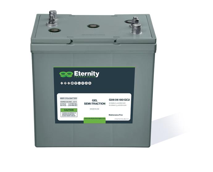
G06 06 180 (GC2)
** CAUTION: Depths of discharge, operating voltages and currents, when designing systems for use at maximum temperatures, will vary.
Mechanical Specifications
Industry Reference
Length (A)
Width (B)
Height (C)
Weight
Terminal (Opt’l)
Cell(s)
Electrolyte
Terminal Torque Nm
NOTE:
Features
Maintenance-free bloc batteries in Gel technology (no topping up during lifetime)
Good high current performance for extreme operating conditions
High-class patented safety valve
700 cycles (DIN EN 60254-1) (IEC 254-1)
Valve-regulated lead-acid battery
Recyclable
Long cycle life
Low self discharge rate allows for up to 2 years shelf life
Classified as a non-spillable battery is not restricted for transportation by:
• Air (IATA/ICAO provision 67)
• Ground (STB, DOT-CFR-HMR49)
• Water (IMDG amendment 27)
Applications
Power Pallet Jacks
Electric Vehicles
Cleaning machines
Electric working platforms
Universal for multiple cyclic applications
ET/DATAGELTRACTION