BRAYDEN TANG
SELECTED WORKS 2021-2023
PORTFOLIO
BRAYDEN TANG
SELECTED WORKS 2021-2023

B.Sc Architecture and Sustainable Design
Singapore University of Technology and Design
Mobile +65 96424630
Email brayden.tang@gmail.com
Linkedin www.linkedin.com/in/braydentangjj
I’ve always been fascinated by the design of the built environment, as it has the power to shape our behaviour and influence our perception of spaces. However, this is not an easy task, given the demands and requirements from different stakeholders, be it the client, future users of even our natural environment.
Through computational means, I hope to develop efficient and streamlined systems to aid decisions through data driven designs, building an environment for all to thrive.
SEP 2021 - MAY 2025
JAN 2024 - JUN 2024
JUN 2022 - AUG 2022
SINGAPORE UNIVERSITY OF TECHNOLOGY AND DESIGN Architecture & Sustainable Design Bachelors of Science
AALTO UNIVERSITY
School of Arts, Design and Architecture Global Exchange Programme
UNIVERSITY OF LOS ANGELES
School of Architecture and Urban Design Summer Programme
JAN 2017- NOV 2018
RAFFLES INSTITUTION
H2 Physics, Chemistry, Math and Art
GCE Singapore-Cambridge ‘A’ Levels
WORK EXPERIENCE
AUG 2023 - DEC 2023
HKS ASIA PACIFIC DESIGN CONSULTING PTE. LTD.
Architectural Intern
Assisted with Building Design, Renderings and Presentation Decks
CO-CURRICULAR ACTIVITIES
FEB 2024 - MAY 2025
MAR 2023 - FEB 2024
MAY 2022 - FEB 2023
MAY 2022 - FEB 2023
ARCHITECTURE AND SUSTAINABLE DESIGN PILLAR Senior Pillar Representative
ARCHITECTURE AND SUSTAINABLE DESIGN PILLAR Sophomore/Junior Pillar Representative
SUTD MOUNTAINEERING CLUB President
SUTDIO (ARCHITECTURE AND CRAFTS CLUB) Secretary
STUDENT SERVICE AWARD (INDIVIDUAL)
TOP STUDENT FOR 02.003 SOCIAL SCIENCE
SUTD HONOURS LIST 2021/22
SUTD UNDERGRADUATE MERIT SCHOLARSHIP
SKILLS
MODELLING RENDERING
DESIGN
OTHERS
LANGUAGES
RHINO 7, GRASSHOPPER, SKETCHUP, BLENDER
VRAY, UNREAL ENGINE 5, ENSCAPE, D5
PHOTOSHOP, ILLUSTRATOR, INDESIGN, PREMIERE PRO WORD, POWERPOINT, EXCEL, PYTHON ENGLISH, MANDARIN CHINESE
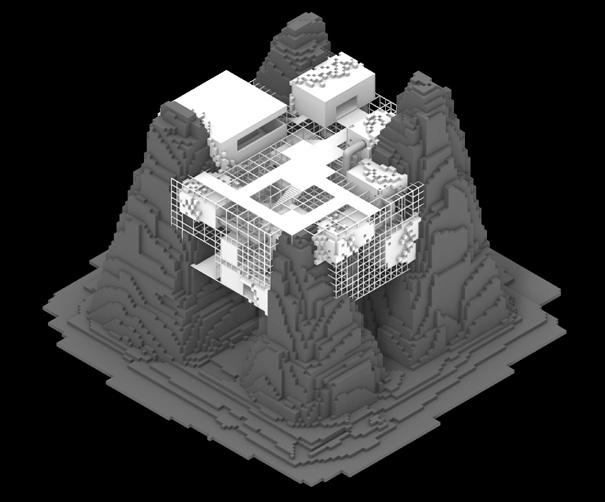
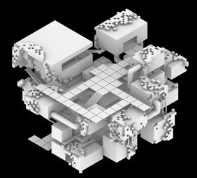
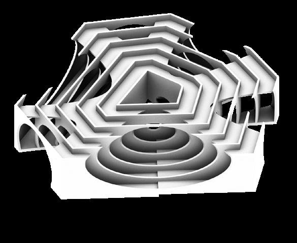
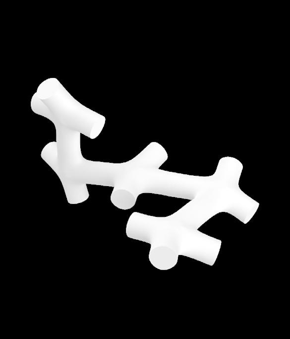
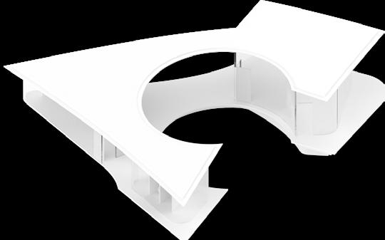
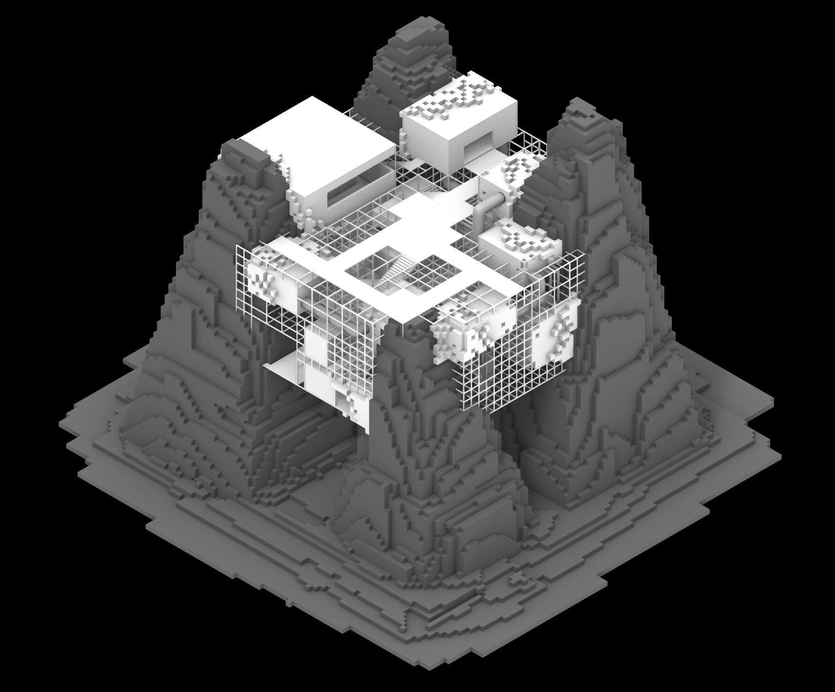
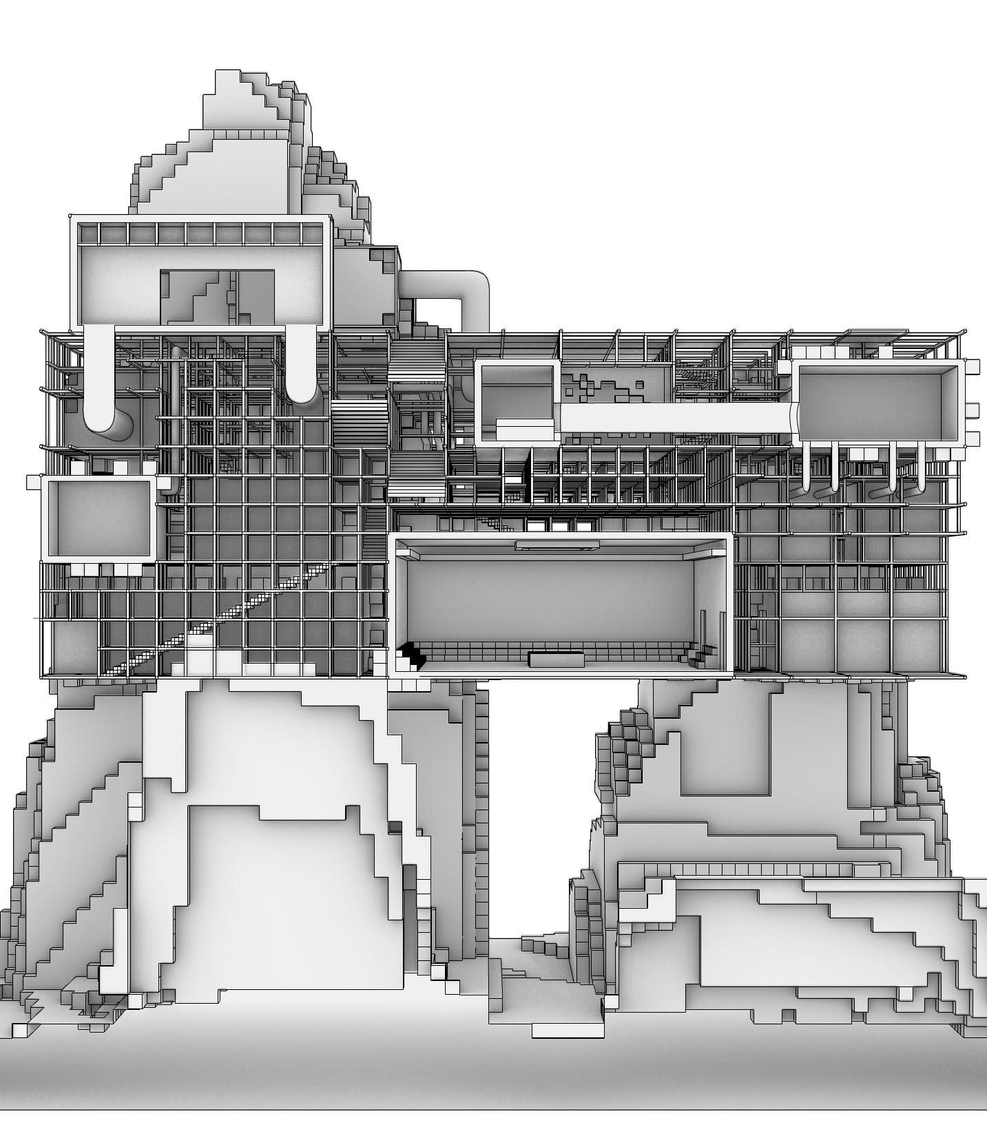
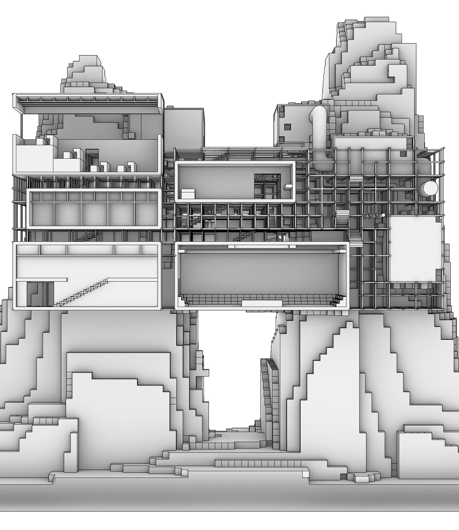
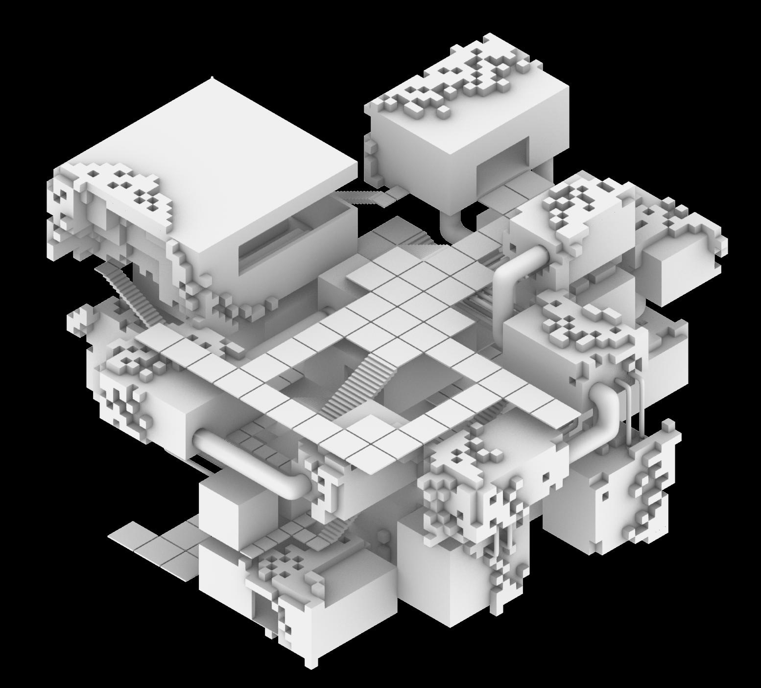
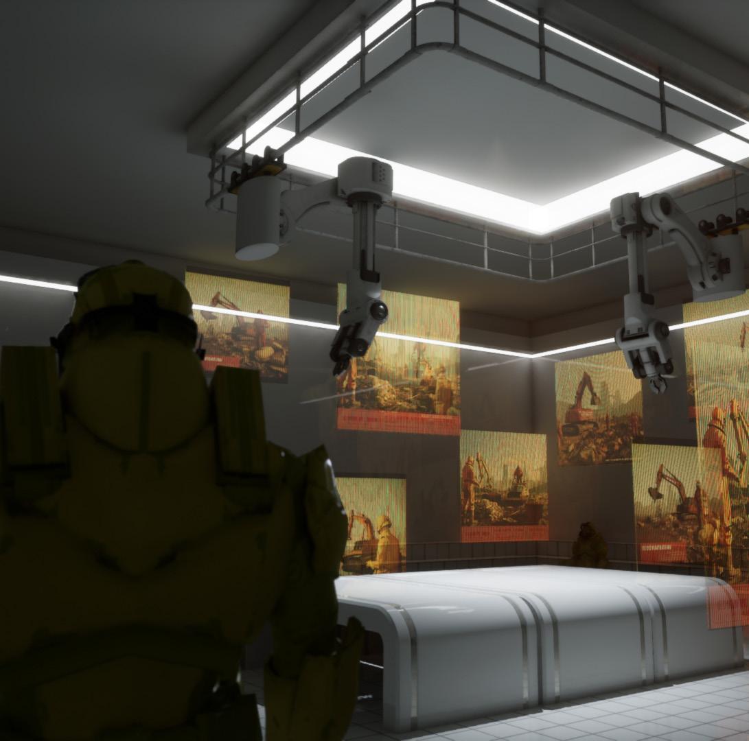
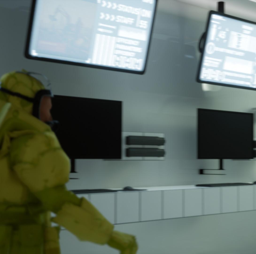
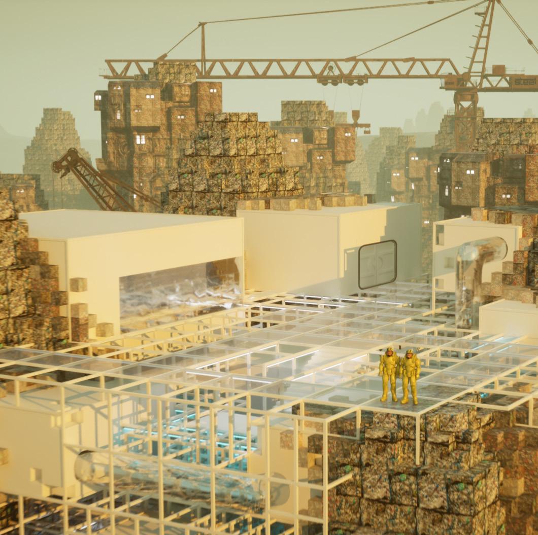
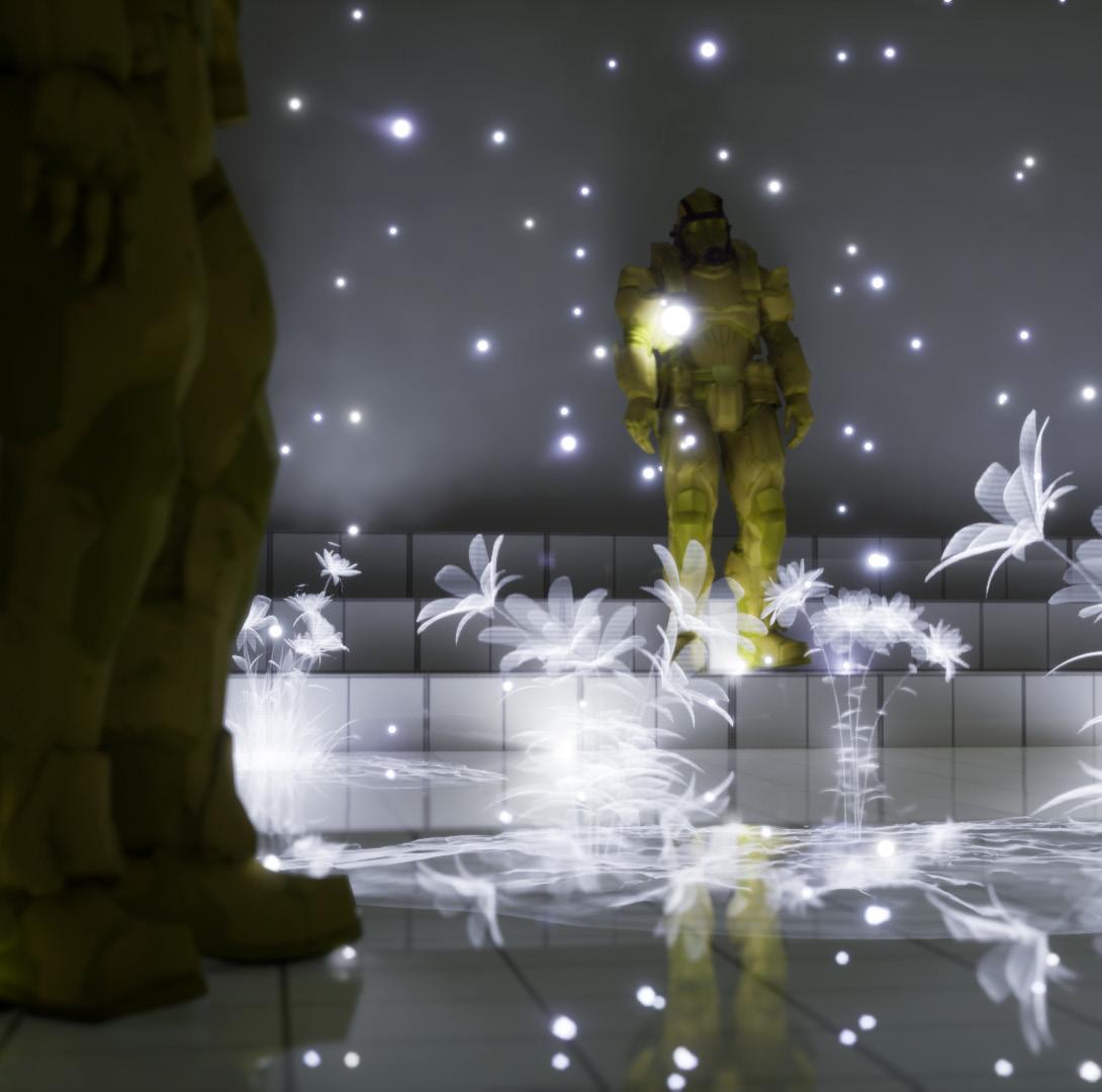
LIFECYCLE is cemetery which sits in the context of a speculative dystopian future.
Presently, the global trash problem is a pressing issue, with over 2 billion metric tons of municipal solid waste being generated every year, and it is expected to rise to 3.4 billion by 2060, a number that would greatly strain ecosystems and pollute waterways.
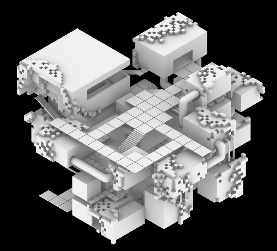
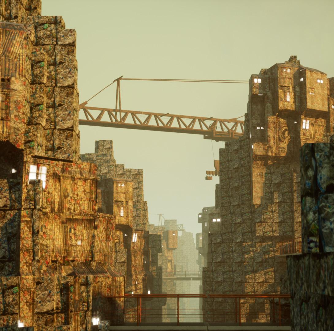
As such, this future is in a state where trash has overwhelmed the surface of Earth, making the polluted grounds uninhabitable for life. The sole option that allows mankind to persist is to live upwards.
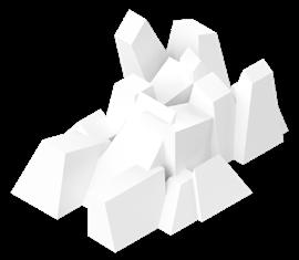
In this reality, this is achieved through harnessing trash itself, compacted into blocks and stacked to form towering mounts suitable for dwelling. The cemetery is designed to be built within the trash mounts and meant to serve as a facility for the deceeased to be processed.
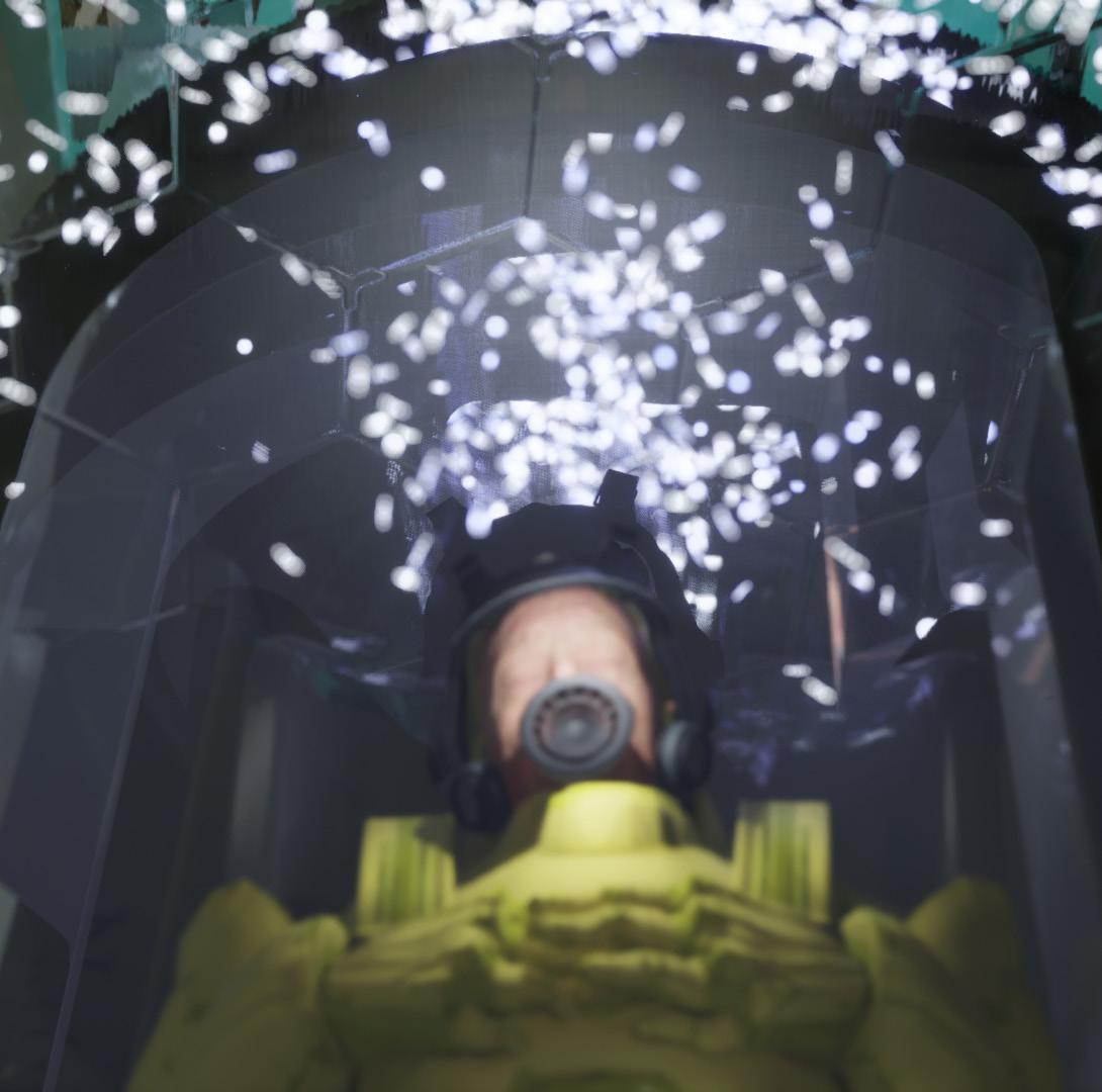
This project challenges traditional ideas about building materials, as well as an understanding of how architecture responds to human behaviour and interactions accommodated with the digital realm.

THE PROTO-CEMETERY: LIFECYCLE // SITE MASSING//
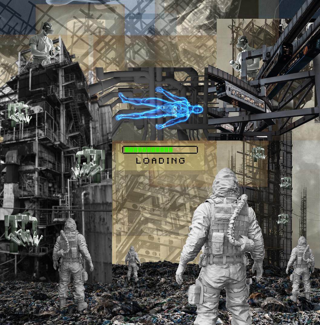
PICTURE COLLAGES
WORLD BUILDING AND NARRATIVE
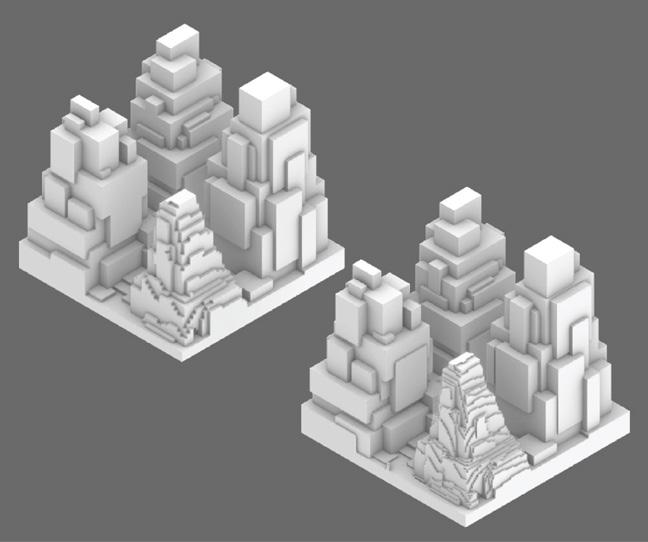
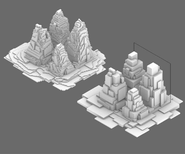
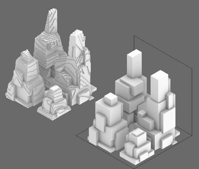
SITE DEVELOPMENT
DIGITAL MODEL ITERATIONS
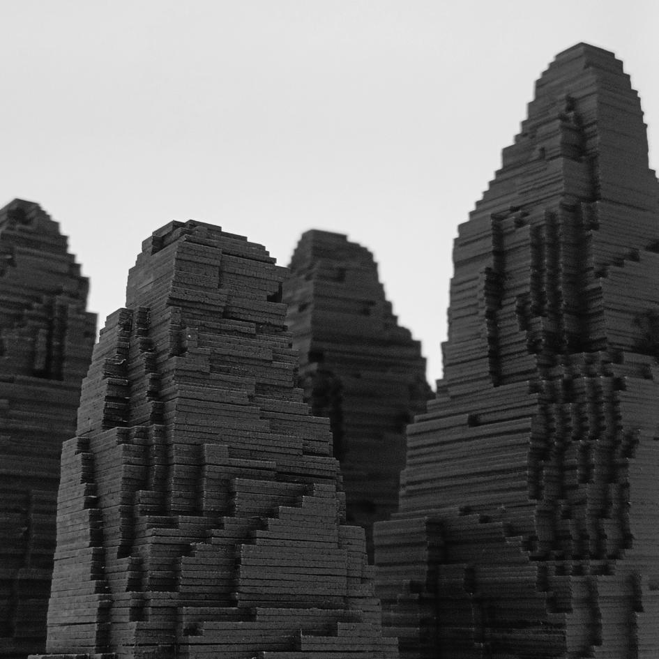
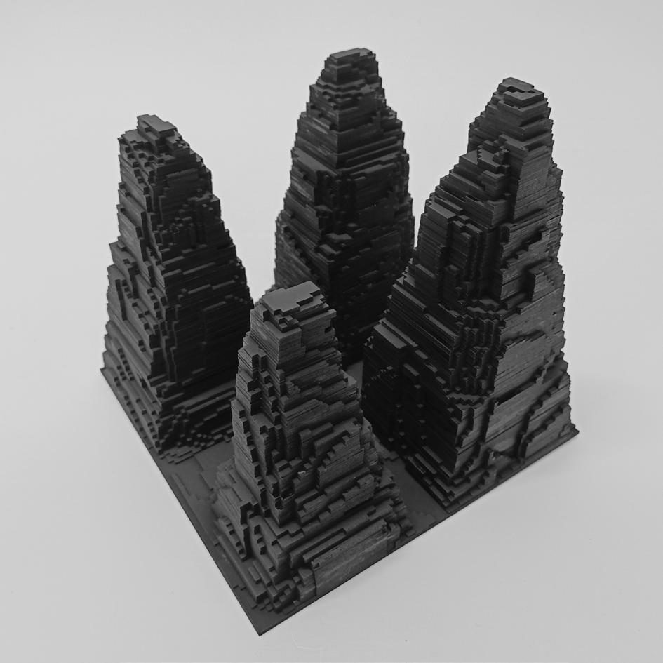
SITE DEVELOPMENT PHYSICAL MODEL
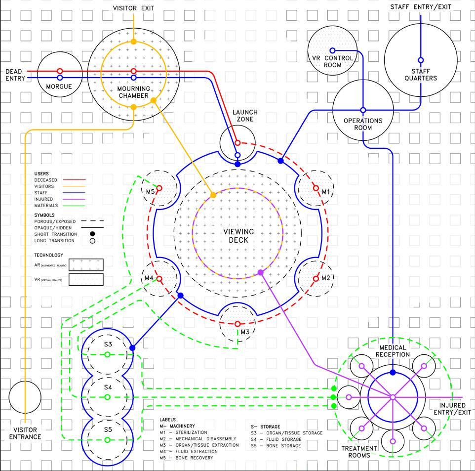
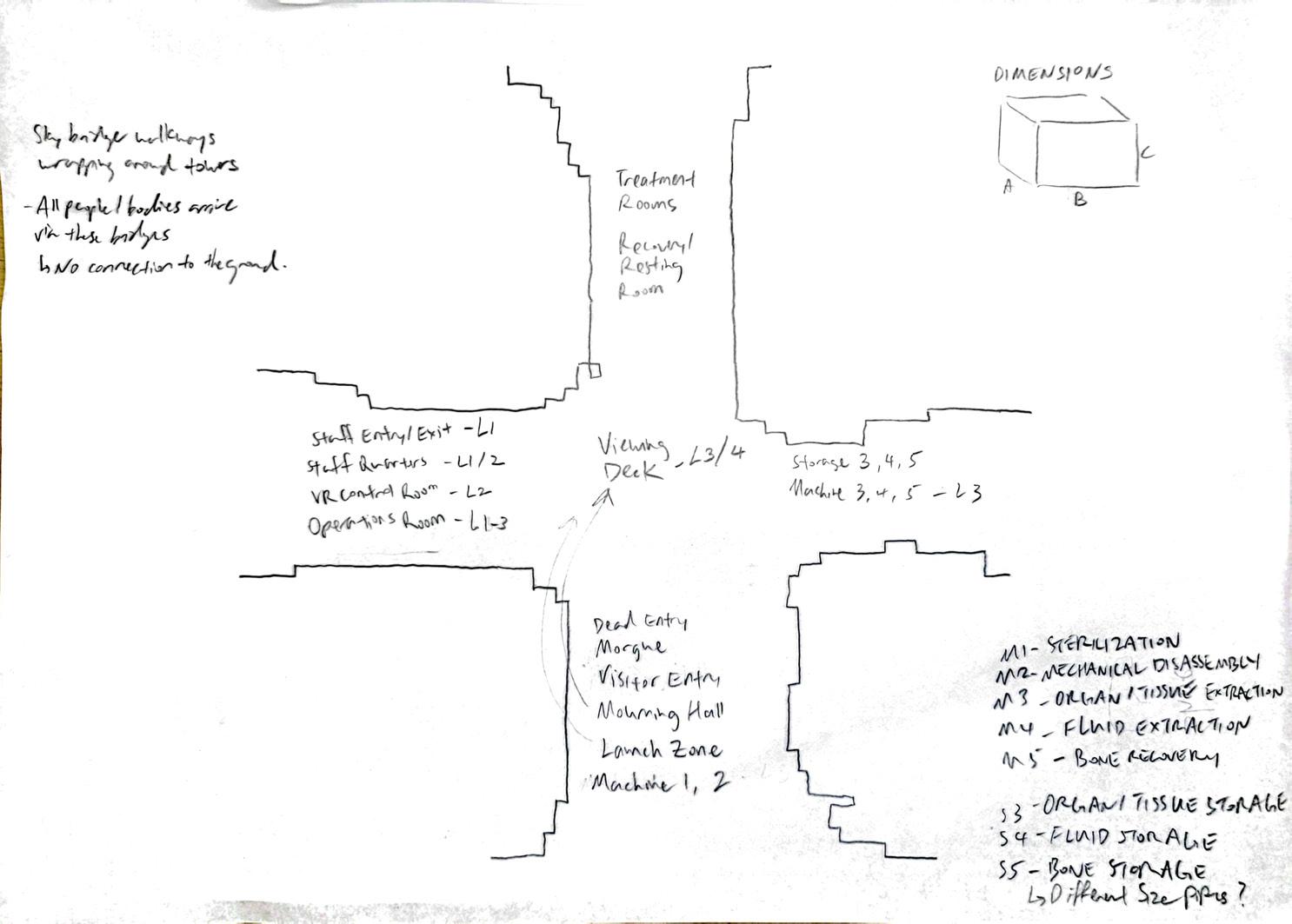
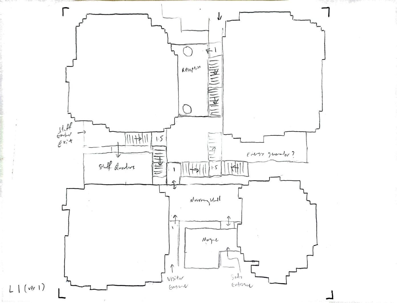
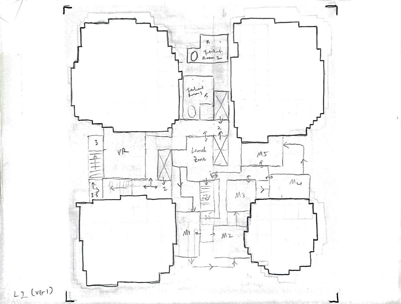
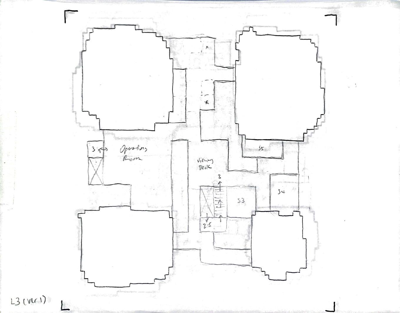 FLOOR PLAN SKETCHES
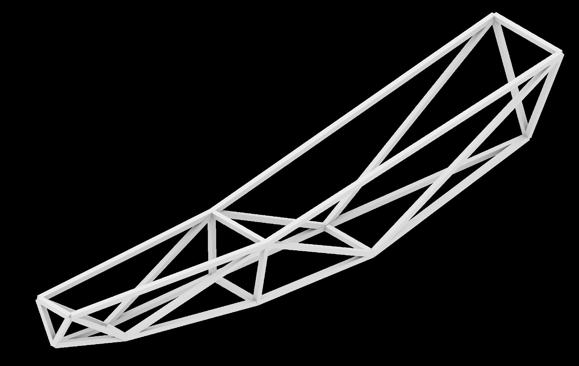
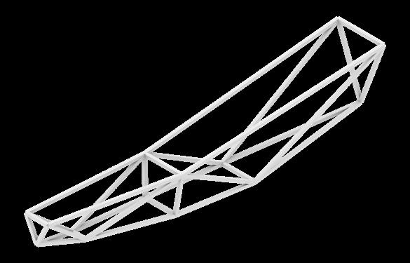
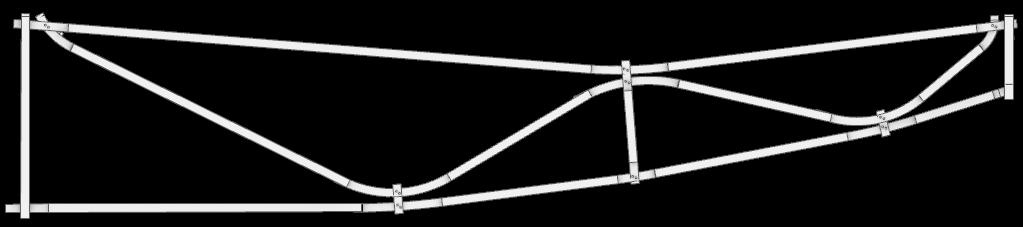
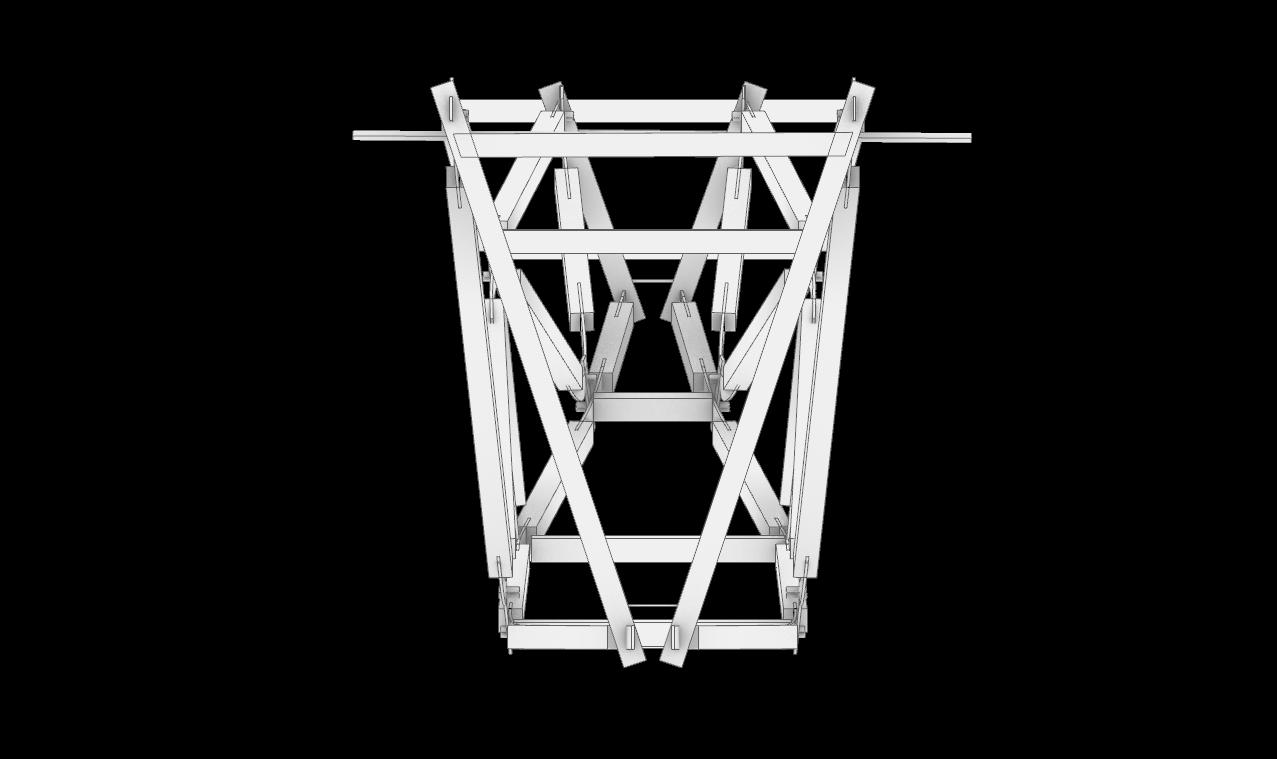
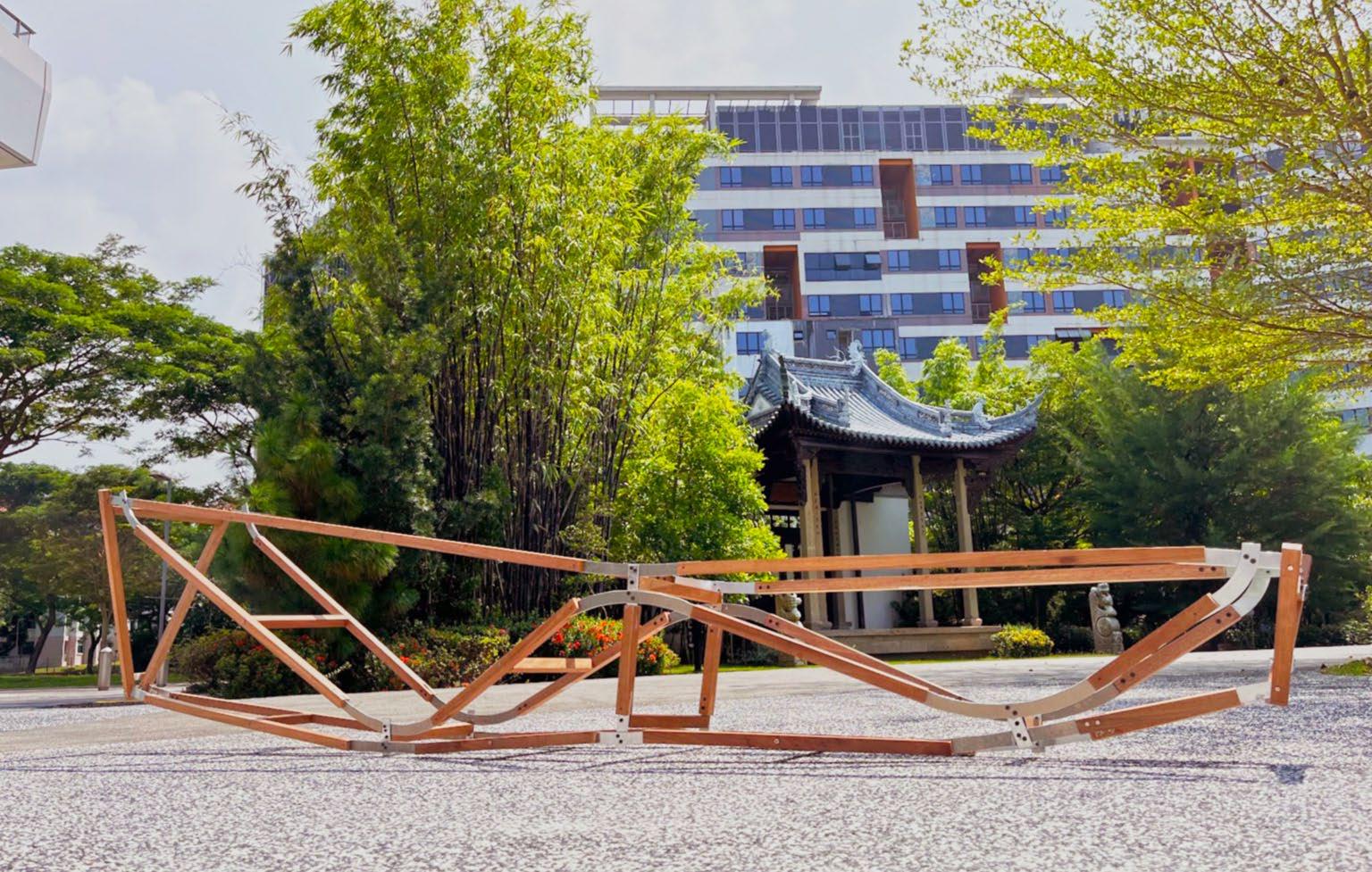
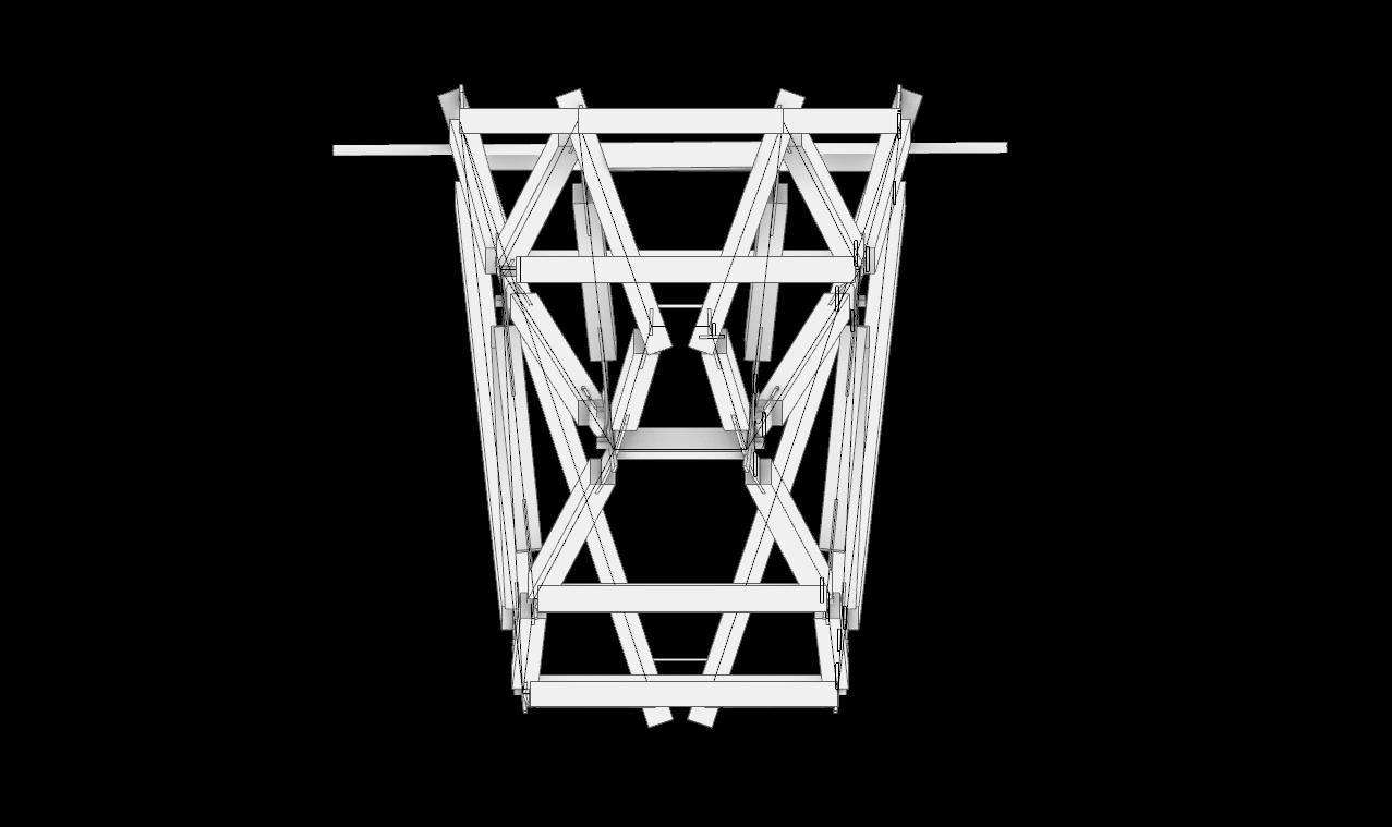
HELIX is an investigation on unconventional truss designs. The focus is on utilizing parametric design principles to optimize specific parameters, constrained by limited materials.
Drawing inspiration from the Helix Bridge found in Marina Bay, Singapore, we referenced the intriguing design that breaks free from conventional truss structures.
3 approaches were used to develop the design, each with varying degrees of freedom for the position of the beams. The outcome of this study is a truss design that incorporates nonplanar joints and introduces undulating truss patterns, deviating from the typical triangulation-based arrangements found in conventional designs.
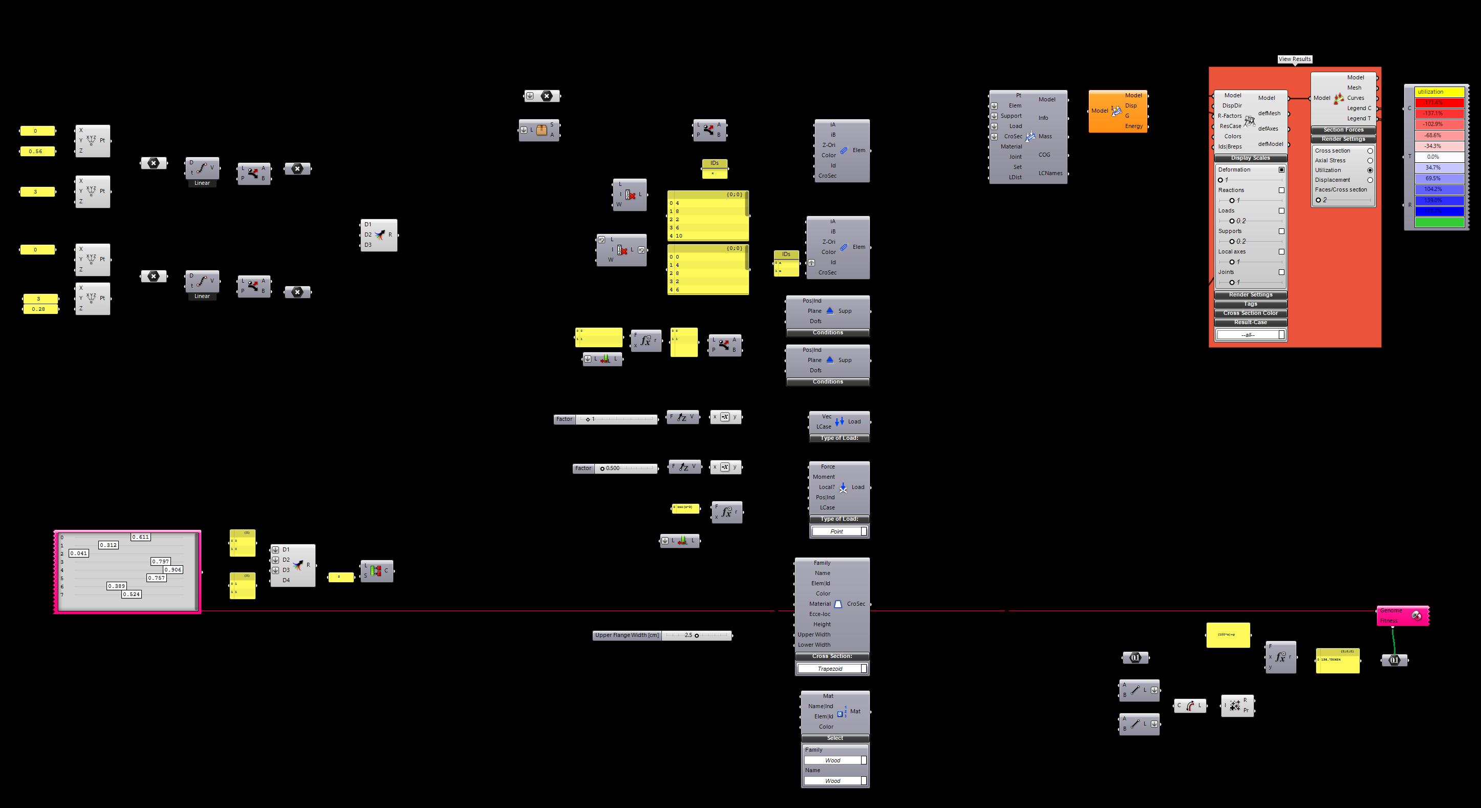
APPROACH 1 GRASSHOPPER CODE
Approach 2 optimizes the position of points randomly placed within a bounding connections
Initially, all points box space However, find a solution sections, enabling faster.
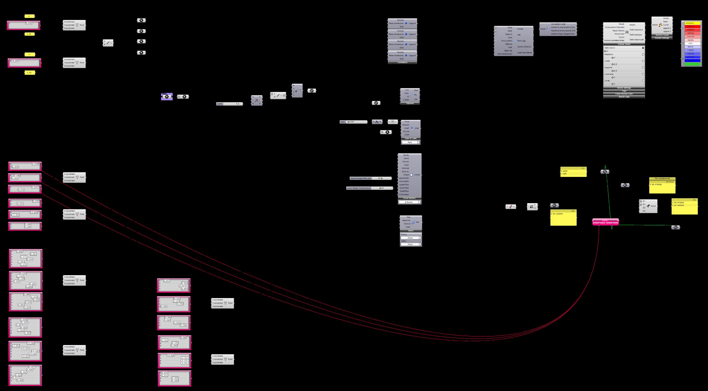
APPROACH 2 GRASSHOPPER CODE
Approach 1optimizes the positions of vertical beams connecting the top and bottom horizontal beams
generate a design that is skewed in either aspect
The top and bottom beams were first determined through the marking of the endpoints.

However, the code does not account for utilization Hence, certain results produced are not feasible Additionally, the code is too restrictive, with results often being in the shape of already existing trusses
Therefore, a new approach that allows for more freedom for the points to break its form is required Approach 1: Along Beams Lengthwise – Results
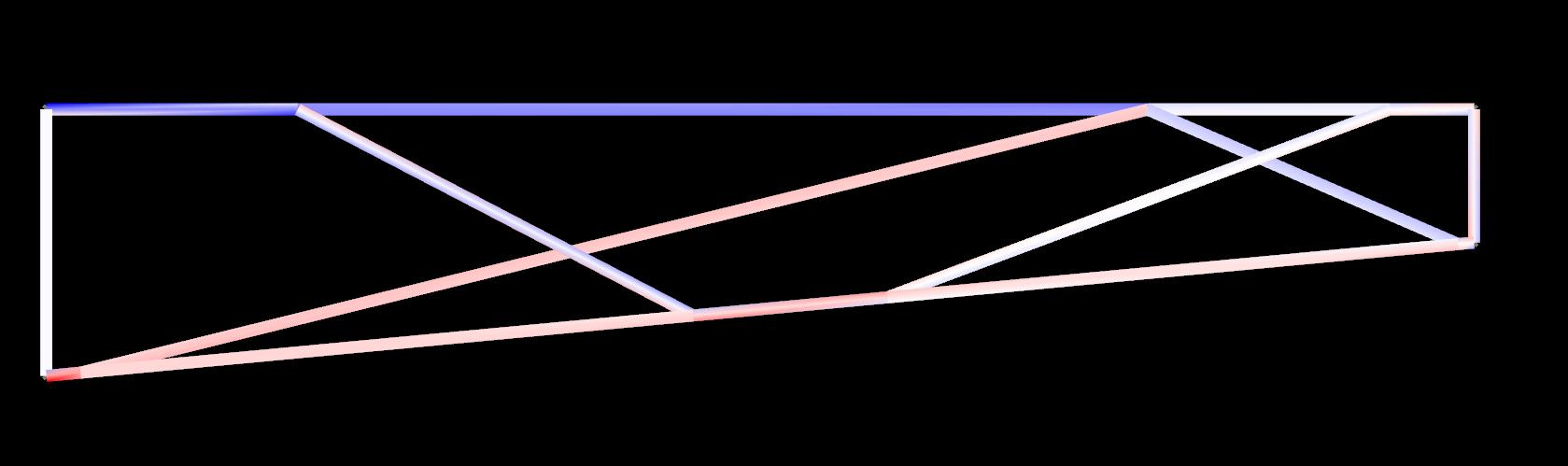
The position of the connecting bems are based on a parameterised position along the top and bottom. These beams are placed into the model analyser, with the cost being directed into the Galapagos Optimizer.

It is successful in achieving optimised forms that reduce both material usage and strength, however, it does not account for utilization, hence certain results produced are not feasible. The code is also too restrictive, with results often being in the shape of existing trusses.
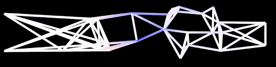
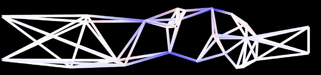
APPROACH 1 RESULTS OF VARIOUS COST FUNCTIONS
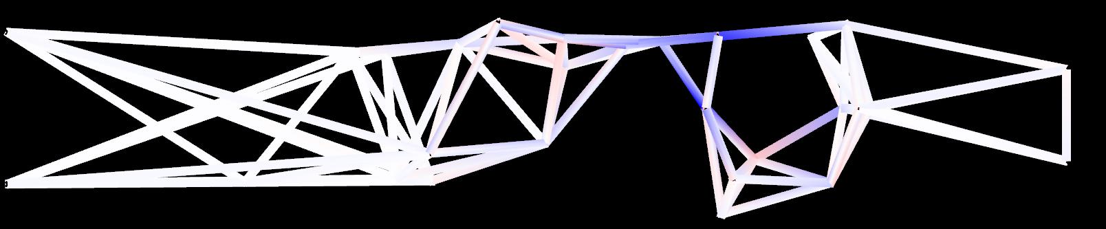
APPROACH 2 INTERESTING RESULTS
From
Approach 2 optimizes the positions of points randomly placed within a bounding box to form the nodes for the beam connections.
Hence,
Approach 2 is successful in achieving irregular forms, however, many of them are not constructable or too challenging to build From the 3 variations, all exceed the utilization value of >2000%
It is successful in achieving irregular forms, however, many of them are not constructable or too challenging to construct (as seen in the 3 variations, all exceed the utilization value of >2000%)
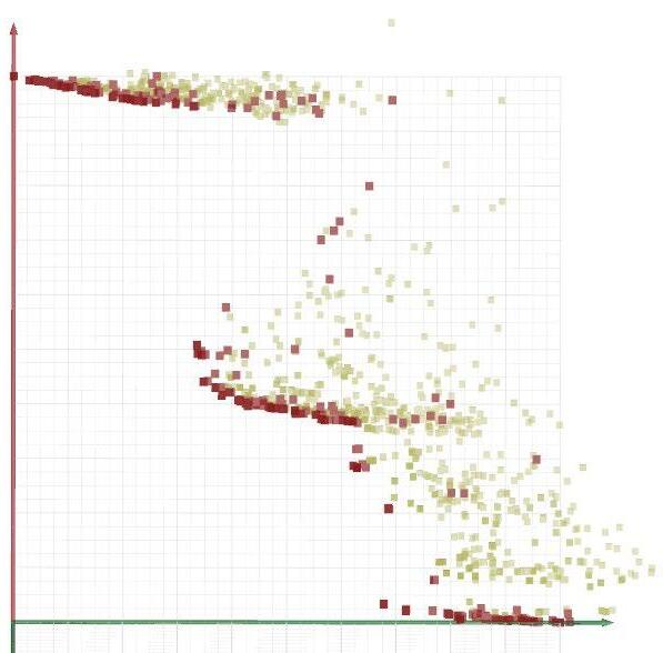
From Graph 1 there is no linear correlation between the total material used and the performance of the cantilever As such, there is no clear relationship that can be inferred to achieve a strong design
Hence, an approach that achieves the distortion of the cantilever shape and still strong would be ideal Therefore, an algorithm that has more control over the position of the points is required
As seen in graph 1, there is no linear correlation between the total material used and the performance of the cantilever, hence there is no clear relationship that can be inferred to achieve an ideal design.
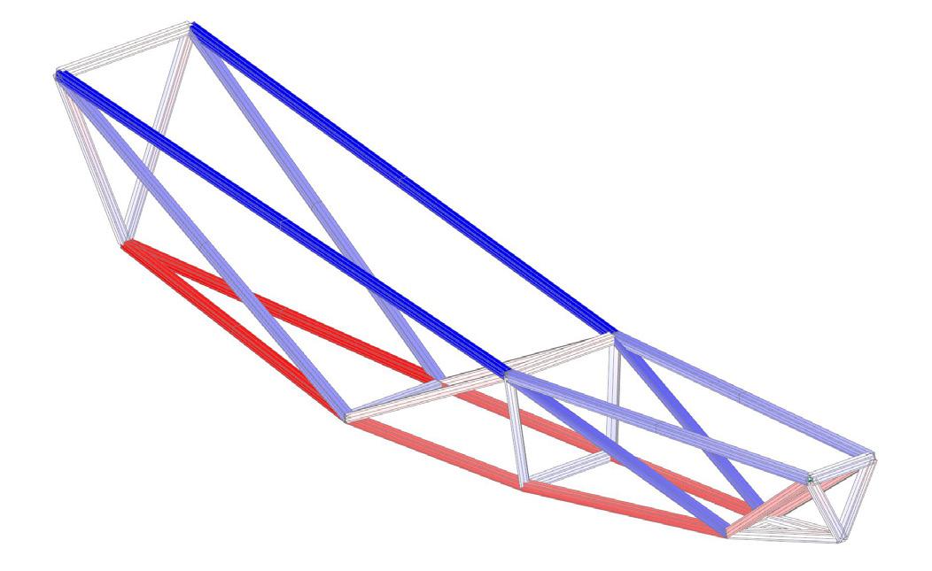
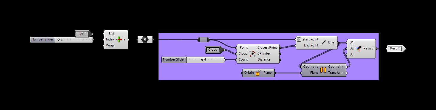
Approach 3 optimizes the position of 4 points placed within a bounding box, after which, the
Ultimately, the final design was chosen based on a balance between detail and overall form, taking into consideration that excessive complexity could complicate construction.
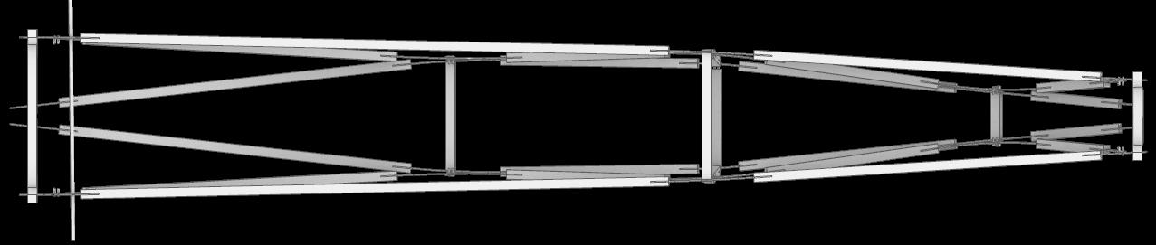
To deviate configurations, triangular
and back surfaces of
points
coordinate
0.56m.
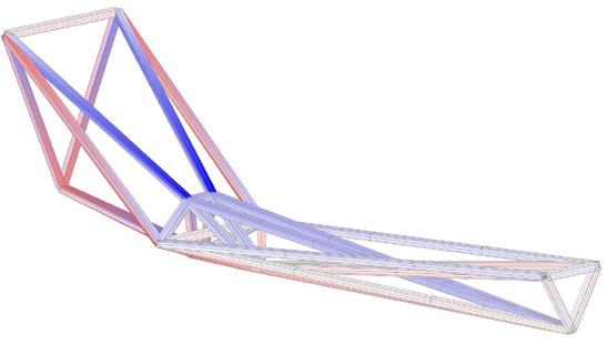
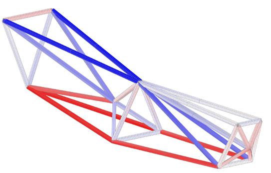
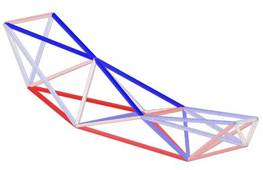
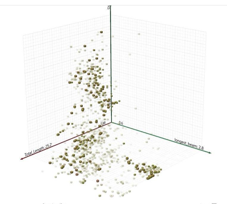
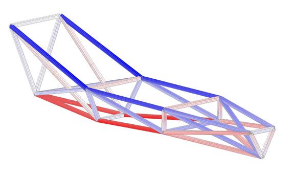
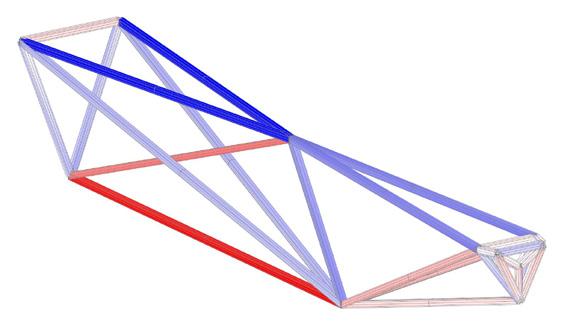
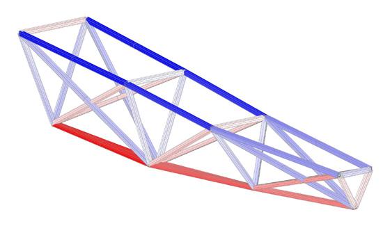
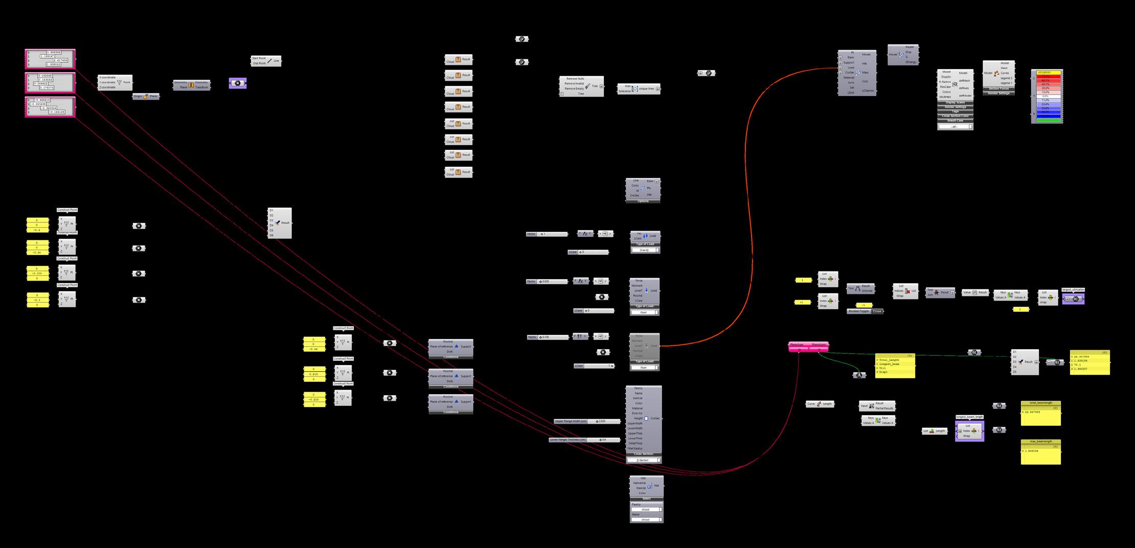
Approach 3 optimizes the positions of 4 points placed within a fixed region, which determines the connection points for the beams, after which, the points are mirrored lengthwise.
To deviate from the conventional truss configuration, a triangular shape was used for both the front and back surfaces of the cantilever structure.
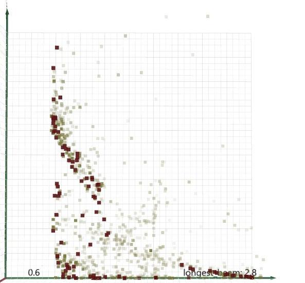
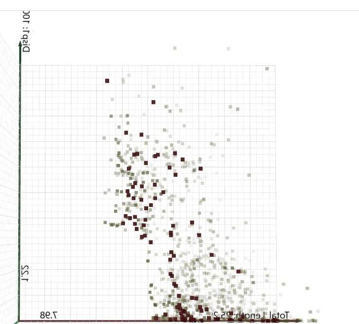
From the graphs, it was found that a greater total amount of material used leads to a smaller deflection. Interestingly, the greater the length of the longest beam, the smaller the value of the maximum deflection.
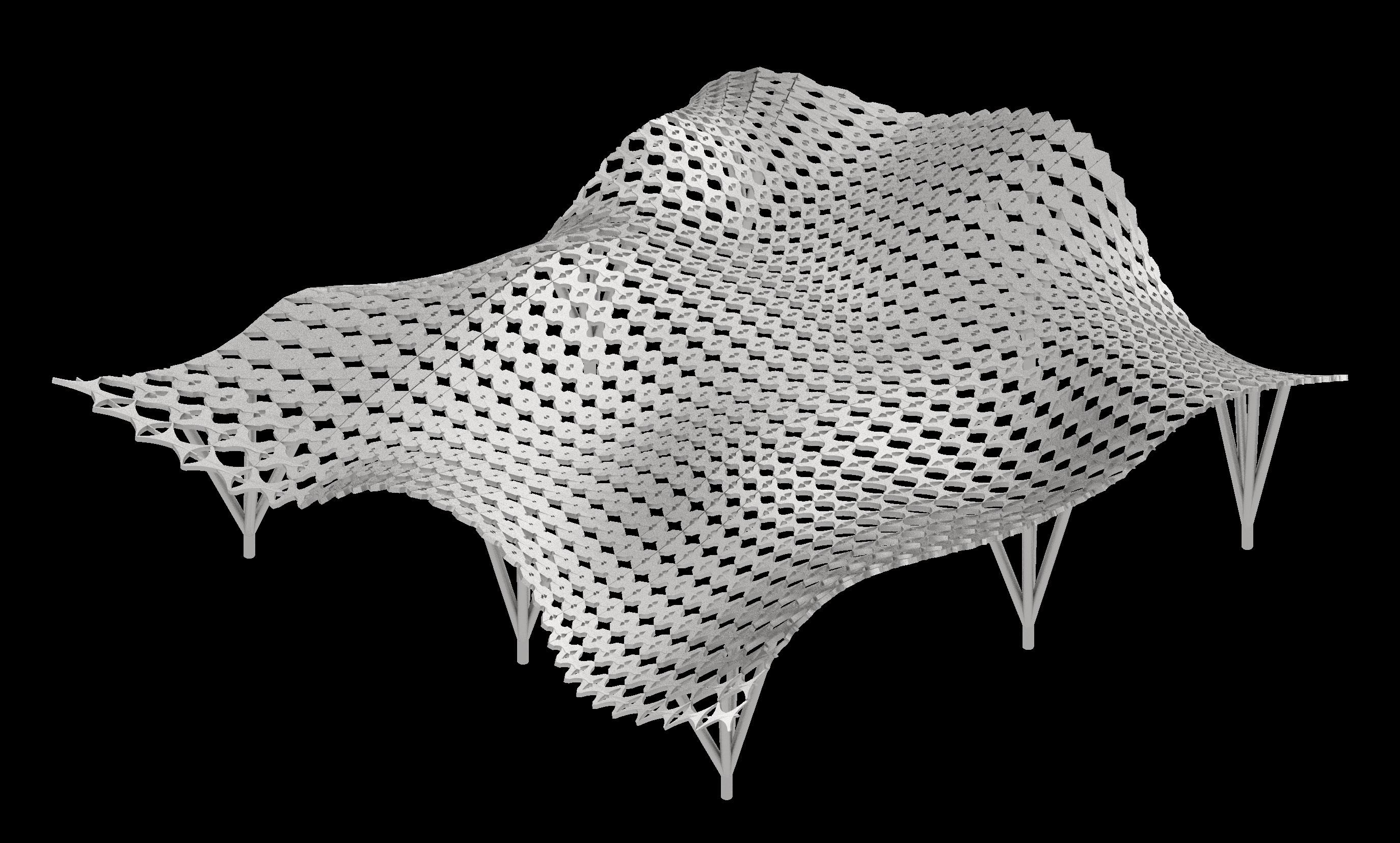
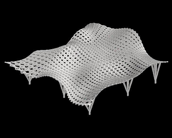
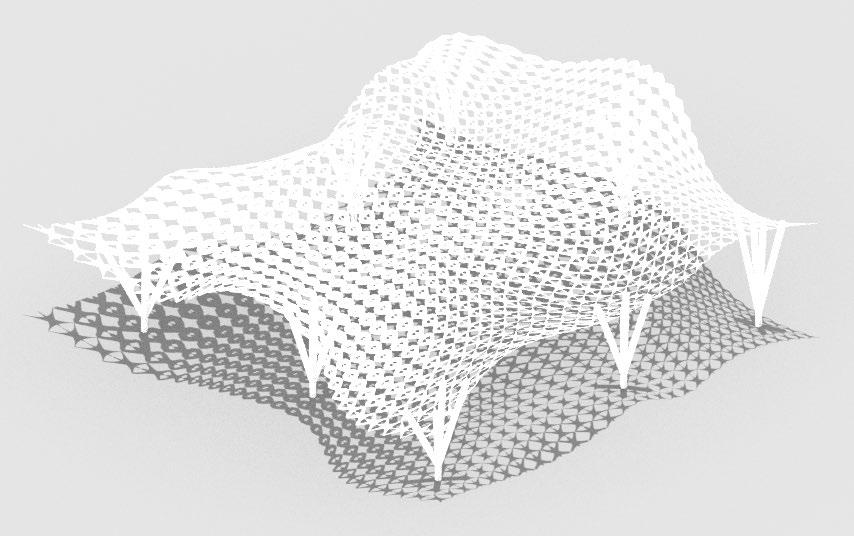
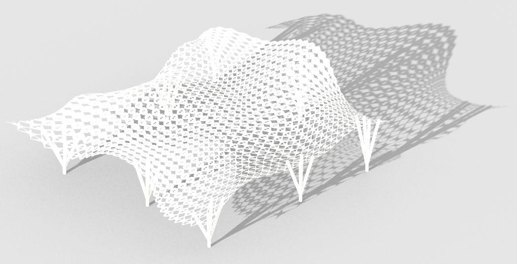
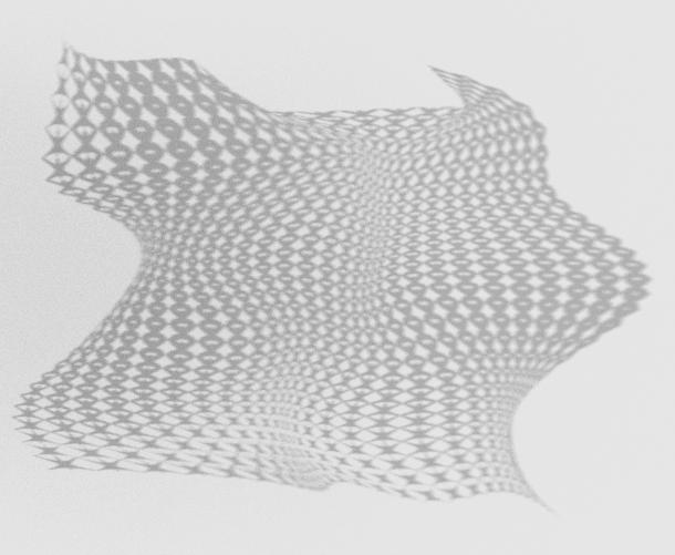
TAPESTRY is a canopy for an outdoor plaza that explores the modulation of light.
Light is a key element in architectural design, and its effects are aesthetic, perceptual and functional.
Too much light may cause glare and generate heat, and too little light may restrict certain programs from being held. As such, light is a crucial consideration for architects and it can be explored through computational means.
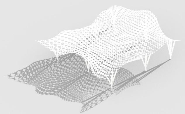
The vision for this canopy is to create a space that promotes intergenerational bonding, with the programs beneath it complemeted by the awe-inspiring intricacy of the canopy’s form and pattern, serving as a conversation starter. The amount of light that passes through a particular region would influence the type of activities that are held below.

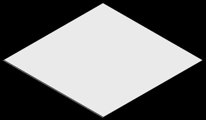
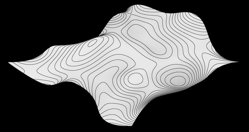
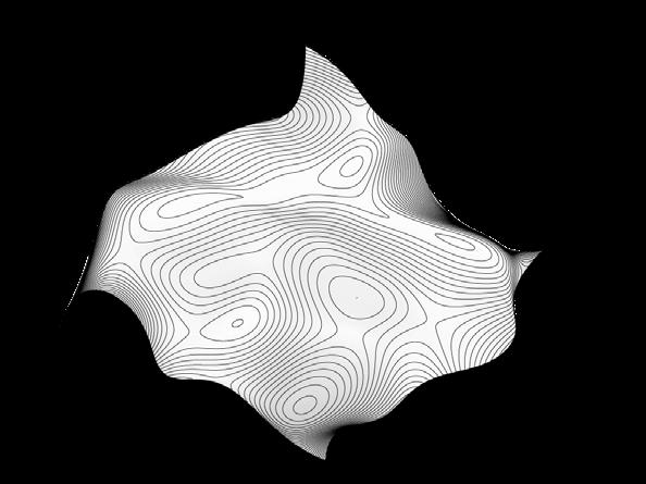
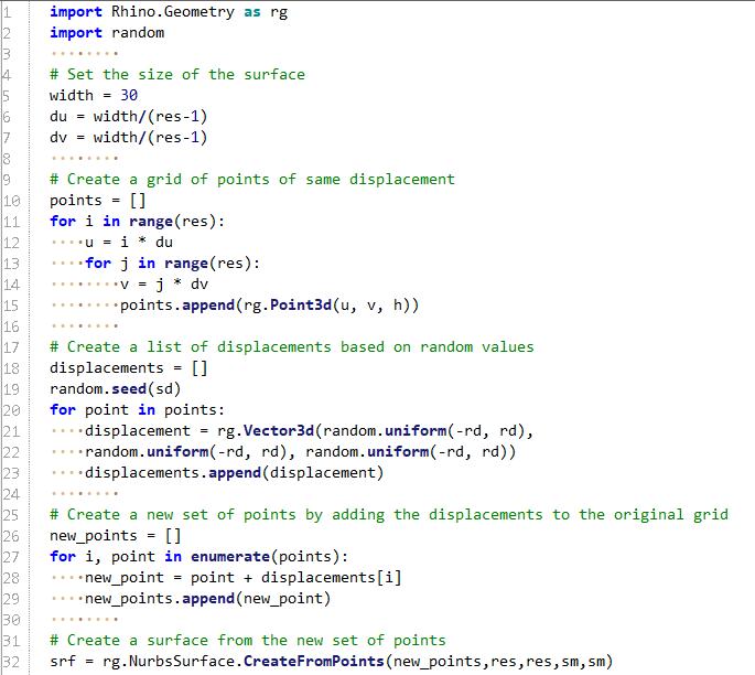
A base surface was first created through a grid of points, in which they are randomly displaced. The surface is then created through the aggregation of these points.

<Introduction to Design Computation> <Photo-philia/Photo-phobia>
<Step 2b - Creation of Pillars>
The pillars are formed by creating lines from the points, where each pillar unit consists of 4 diagonal beams and 1 vertical beam.
<Introduction to Design Computation>
<Step 2b - Creation of Pillars>
I aimed to make the canopy appear like a piece of fabric and use its curvature to influence the shape of the tessalted module.
The center tile where the pillars are located below are predetermined, after which the index of 4 connection tiles are obtained through calculation.
The pillars are formed by creating lines from the points, where each pillar unit consists of 4 diagonal beams and 1 vertical beam.
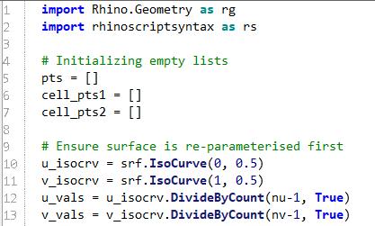
<Photo-philia/Photo-phobia>
The surface is then reparameterized, and then subdivided into smaller square grids.
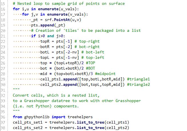
This grid serves as a reference point for the modules which will be populated on the canopy.
The center tile where the pillars are located below are predetermined, after which the index of 4 connection tiles are obtained through calculation.
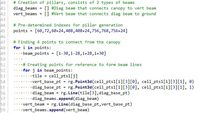
For each tile, as it is stored as a list of 4 points, I referenced the 3rd index in the list, which correlates to the middle point. The x and y values of the vert_base_pt and diag_base_pt coordinates are constructed referencing the middle point, while the z values are set to 0 and 1 respectively.
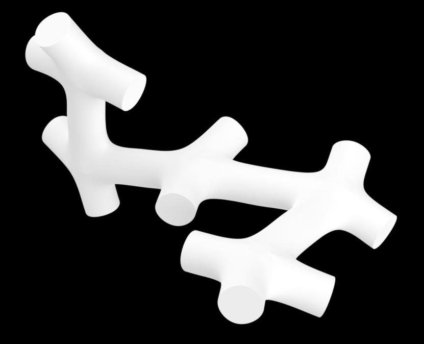
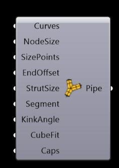
The lines are connected to the Grasshopper ‘Pipe’ block to generated the beams with a radius of 0.2, completing the pillar.
I settled with a variation that managed to achieve a good balance of curvature and flatness, as well as giving a cloth-like appearance.
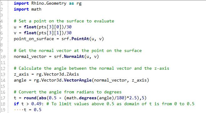
Python code (2b)
For each tile, as it is stored as a list of 4 points, I referenced the 3rd index in the list, which correlates to the middle point. The x and y values of the vert_base_pt and diag_base_pt coordinates are constructed referencing the middle point, while the z values are set to 0 and 1 respectively.
The lines are connected to the Grasshopper ‘Pipe’ block to generated the beams with a radius of 0.2, completing the pillar.
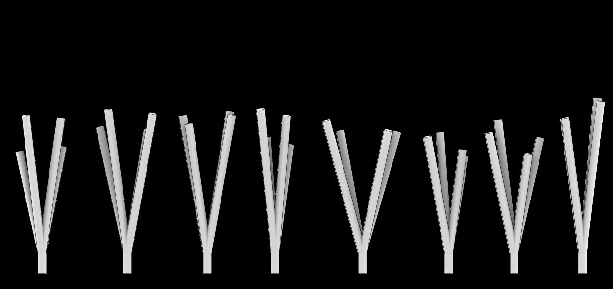
Each pillar consists of 4 diagonal beams and 1 vertical beam.
The position of the pillars, with respect to the canopy, are predetermined. Hence, the index of the 4 tiles that the diagonal beams connect to the vertical beam are calculated.
There are 4 primary components in the code. First, the base surface is created, which establishes the basic form of the canopy. Next, lists of points necessary to define the modules and pillars are generated. The modules are then drawn out by outlining its shape, making a surface and giving them thickness. Finally, the shape of the module is dependent on the parameter calculator, which takes into account the angle of the surface at that point.
Lines are drawn and then piped to form the final pillars.
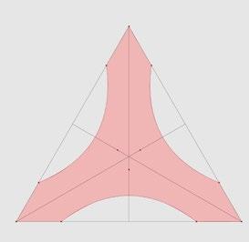
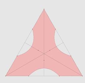
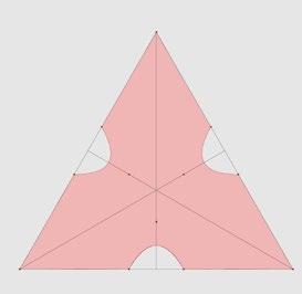
make the modules respond to the intrinsic attributes of the surface.
The base module consists of a triangle, where its shape can be adjusted based on a parameter.
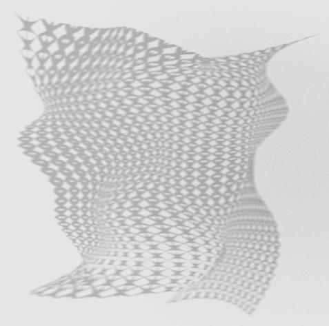
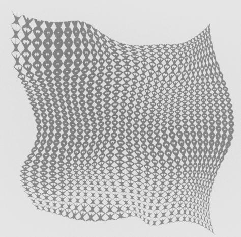
To make the canopy comfortable for users below it, I explored the idea of minimizing the size of the gaps at regions that face directly upwards, and maximizing gaps at regions that are angled away. This not only reduces direct sunlight shining in downwards, but the larger side facing openings still allows for ventilation into the canopy, and it also makes the structure appear light and seemingly “float” in air like a piece of cloth.
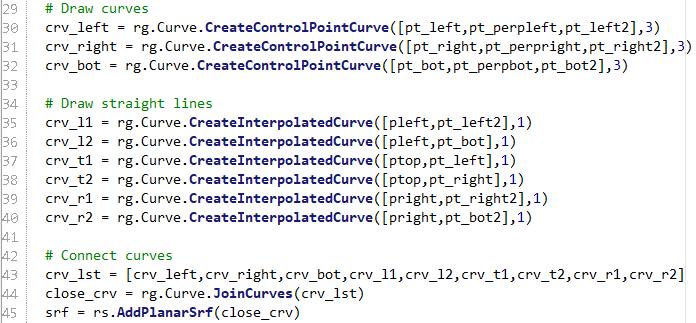
Reference points are created for the adjustment of the shape of the module.
To achieve this, I decided to calculate the tangent of each module with respect to the zaxis, and parameterizing the value which can be used to input and adjust the size of my module.
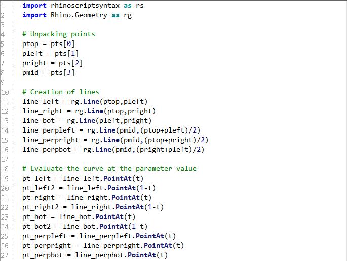
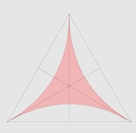
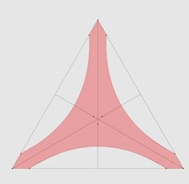
Curves are drawn along each of the 3 sides of the triangle using 3 points, with the 2 end points dictating as anchors, while the center point serves as a controlling point that governs the degree of curvature in the curve.
that I wanted the
to
Considering the size of the gaps in the modules above, I demarcated
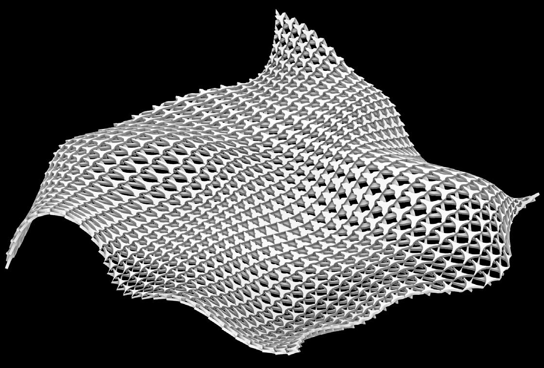
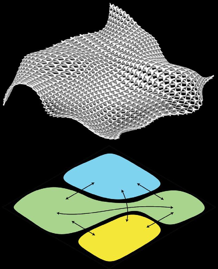
To make the modules respond to the intrinsic attributes of the surface, I explored the idea of minimizing the size of gaps at regiions that face directly upwards, and maximising gaps at regions that are angled away.
This was done through the calculation of the tangent of each module with respect to the z-axis.
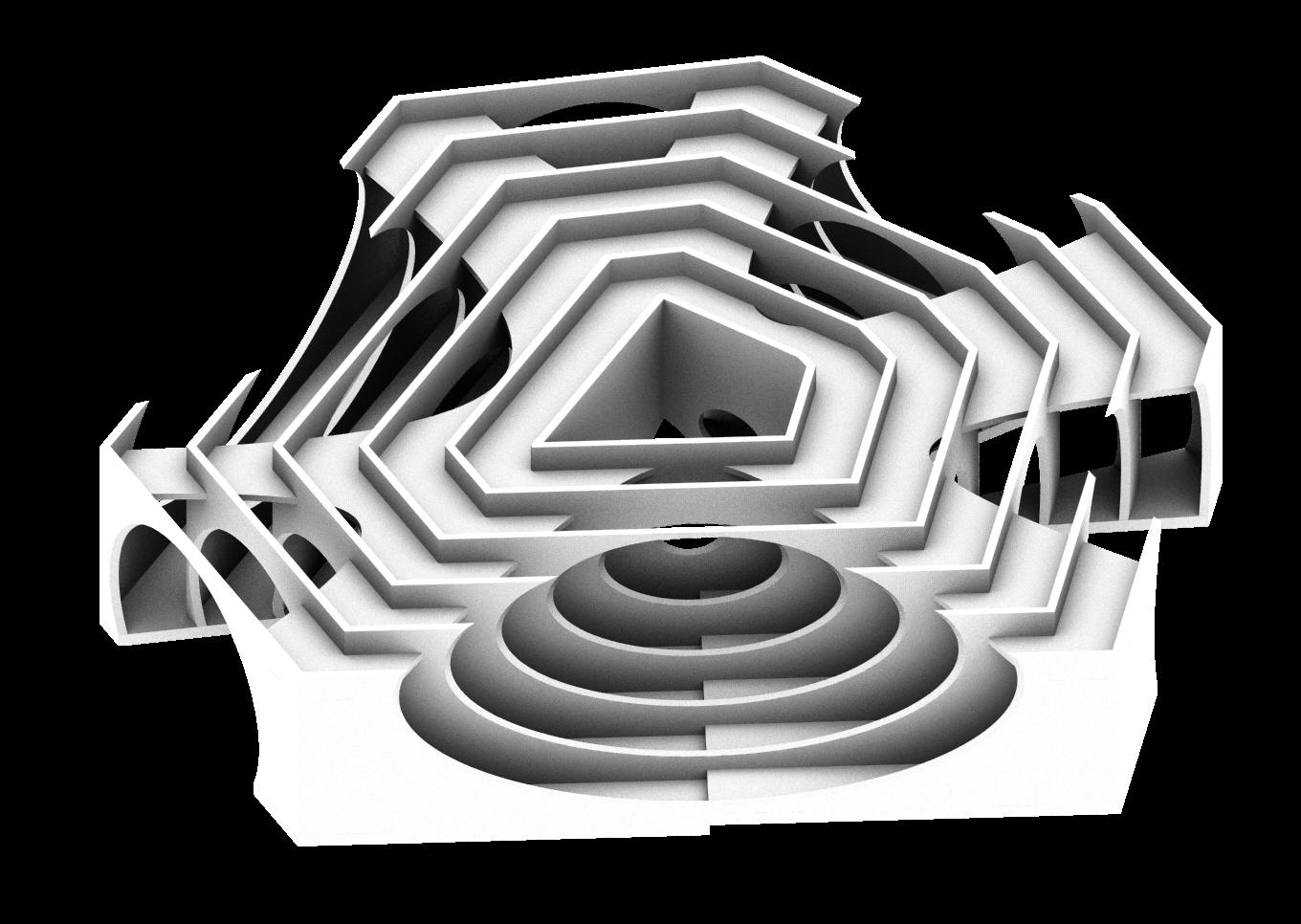
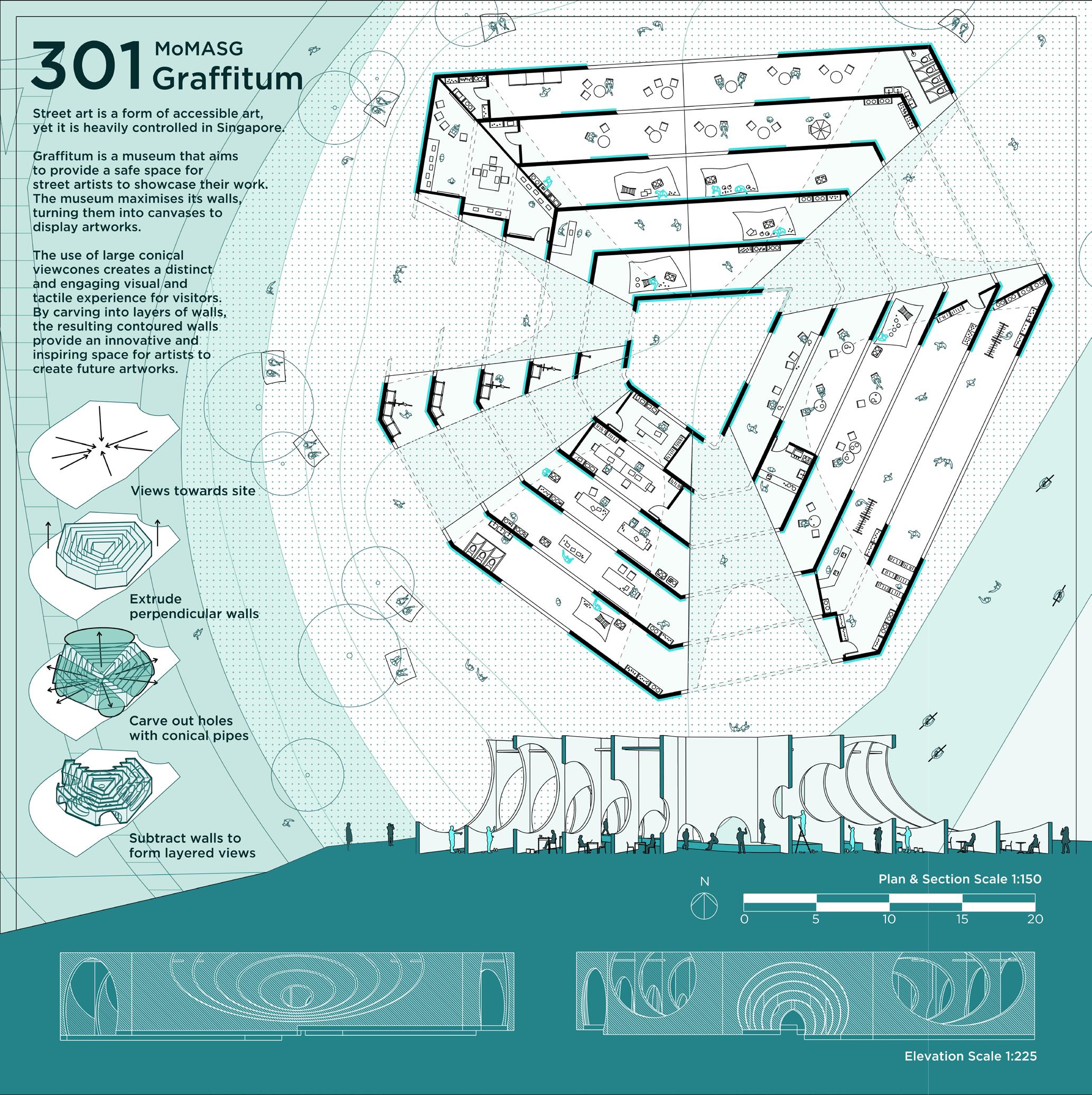
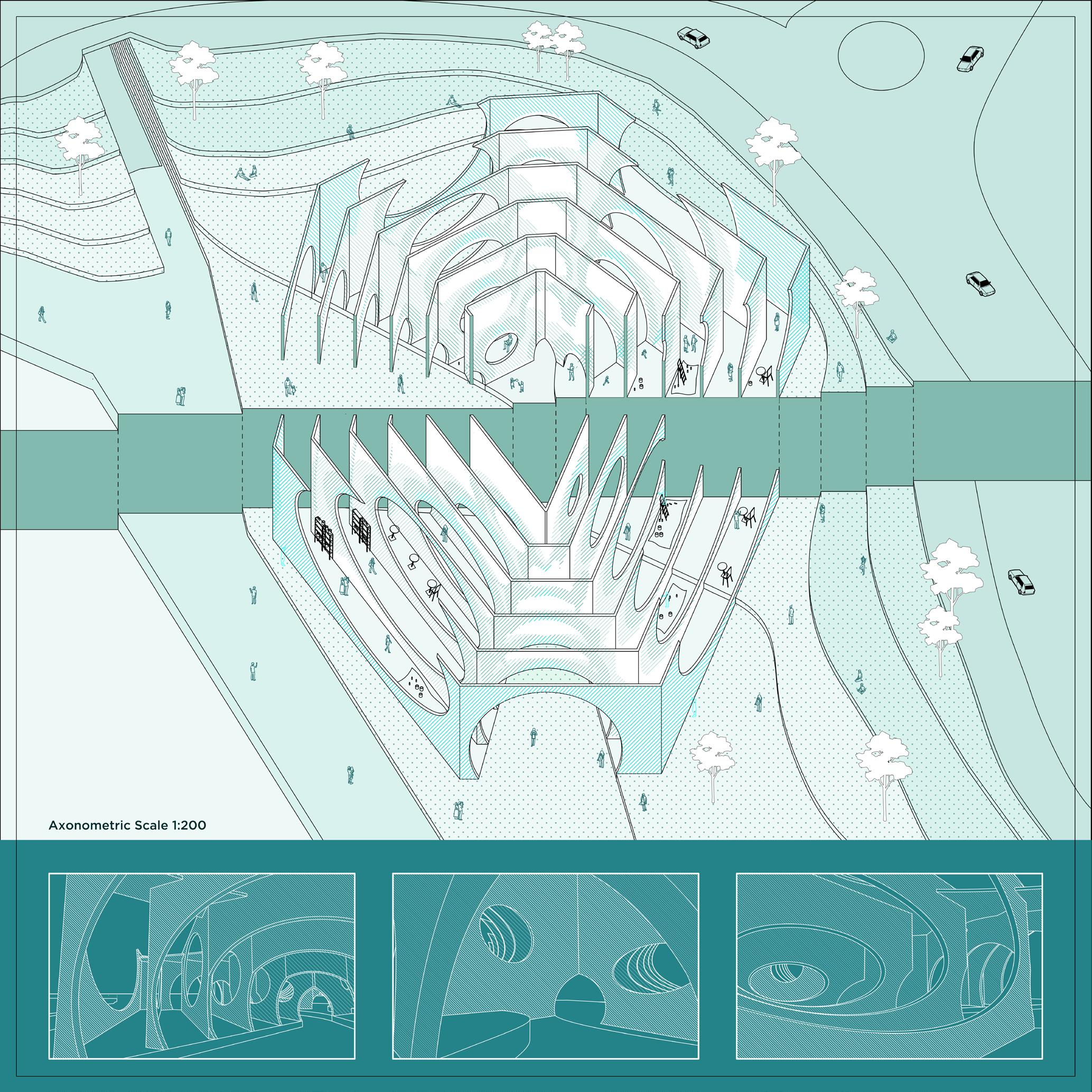
GRAFFITUM is a proposed design for a Singapore MoMA (Museum of Modern Art) Satellite, located in Esplanade Park.
Presently, Singapore has a many different art museums, such as the National Gallery and Singapore Art Museum, which showcases various collections ranging from historical to contemporary modern artworks.
However, an artform shunned and often clamped down on is Street Art. It is an artform practised by many Singaporean artists, yet they do not have a safe space for them to showcase their work.
Hence, this proposal aims to provide the safe space for them to do so. The building is designed in a manner that it maximises its walls, turning them into canvases to display artworks.
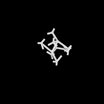
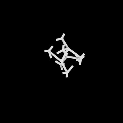
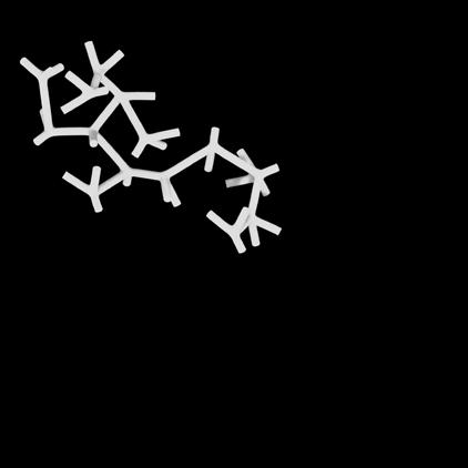
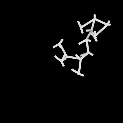
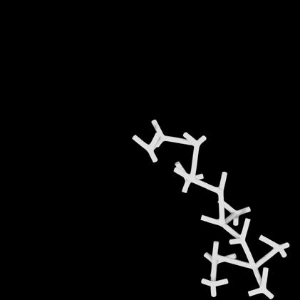
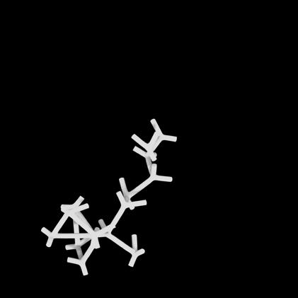
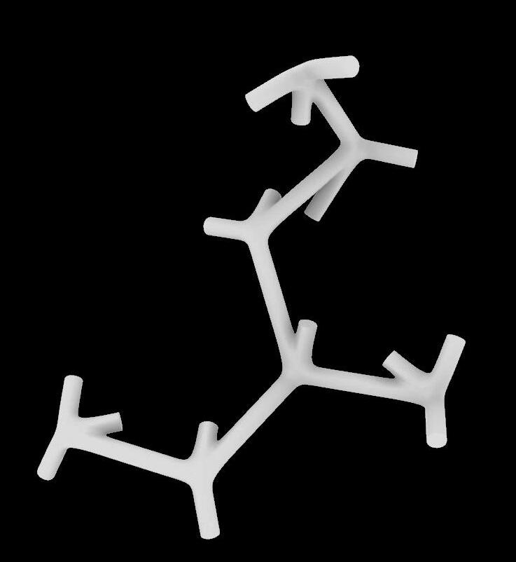
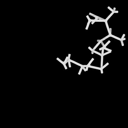
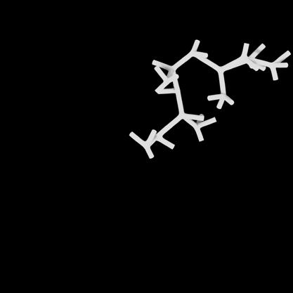
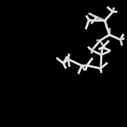
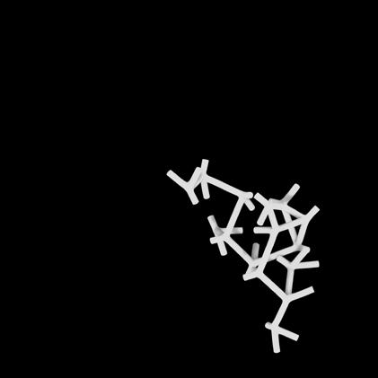
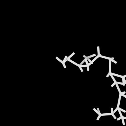
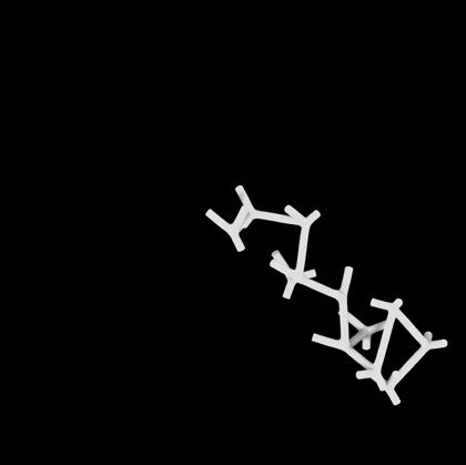
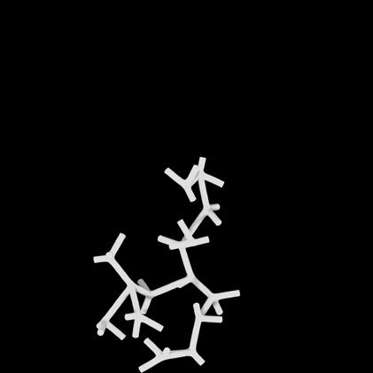
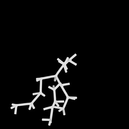
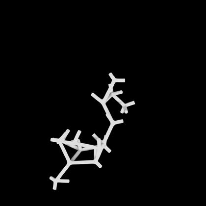
ORGANISCAPE is an investigation into generative algorithms.
Generative design approaches involve creating outcomes from algorithms. In the architecture domain, these outcomes are often material in nature and exhibit traces of their algorithmic lineage through their physical characteristics.
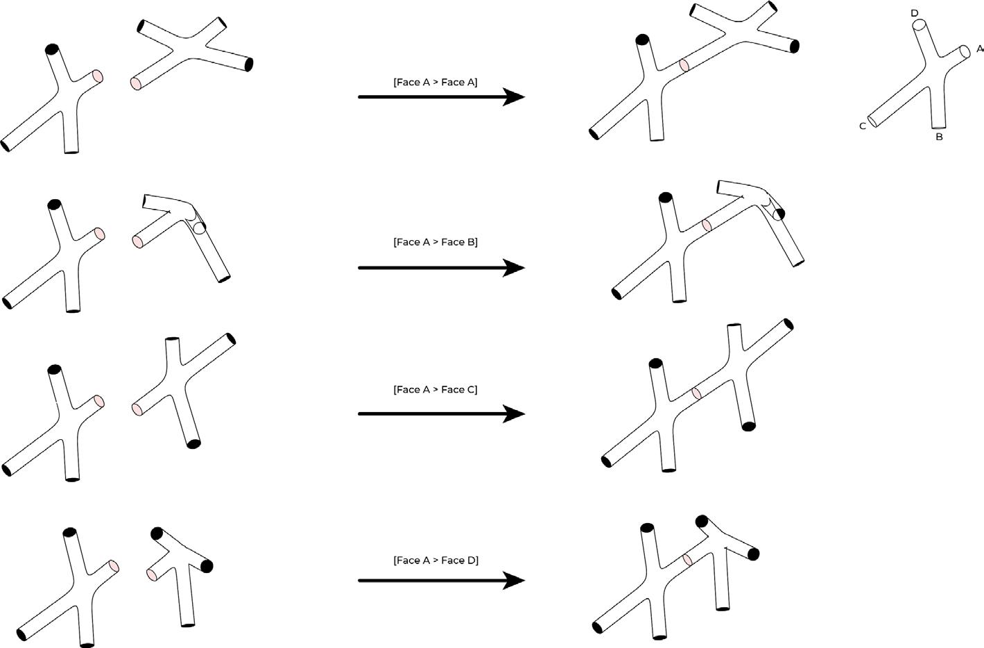
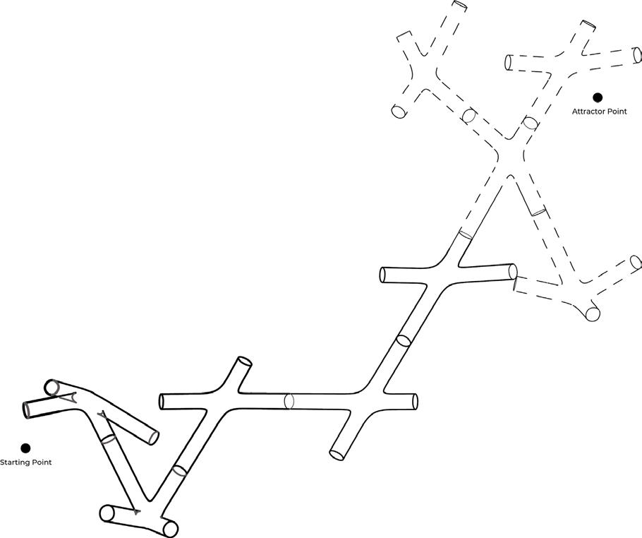
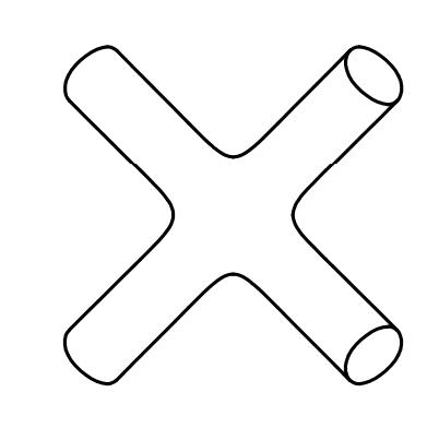
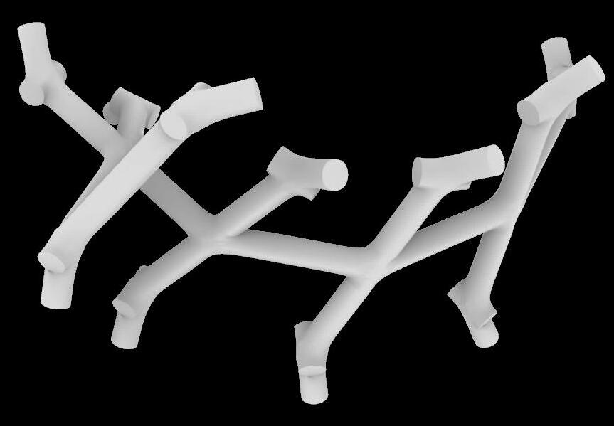
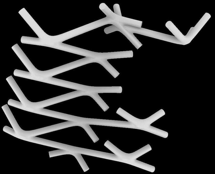
In this project, our group wanted to explore on the growth of modules, which is dependent on its shape, its connecting face and the scalar field.
1 CREATING 4 CURVES
2A GENERATING MODULE
2B GENERATING SCALAR FIELD
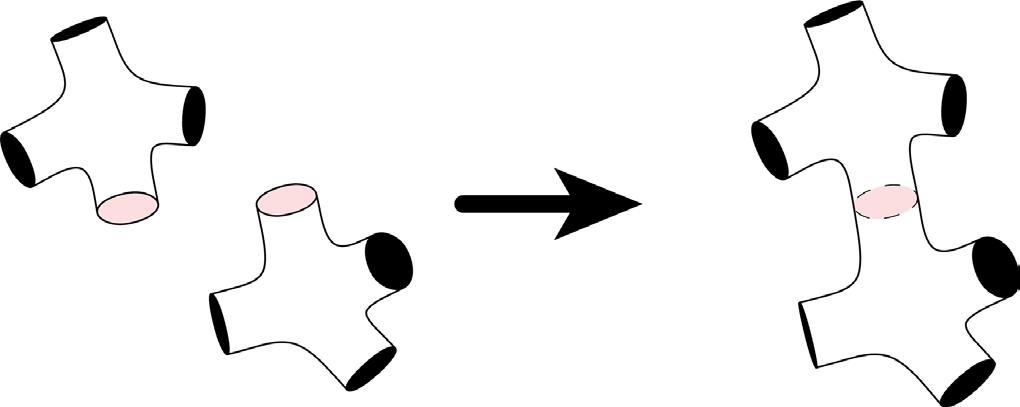
3 COMBINING MODULES

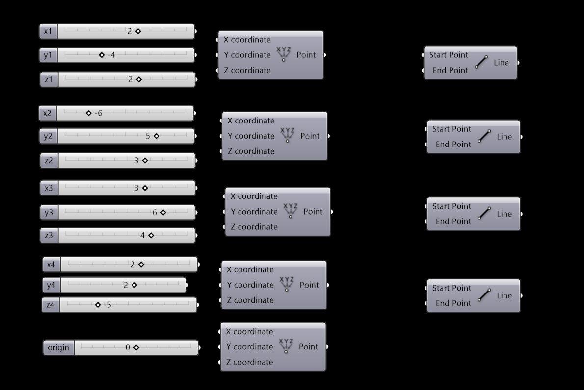
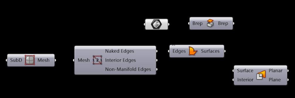
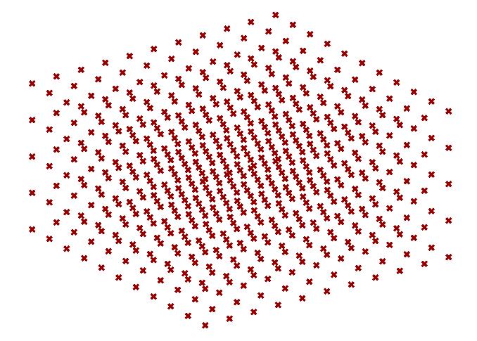
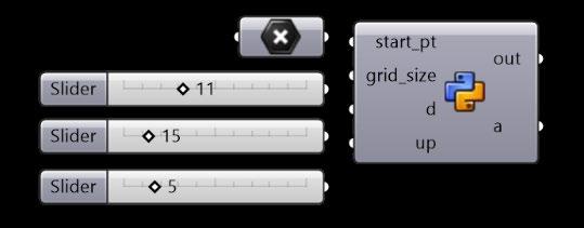
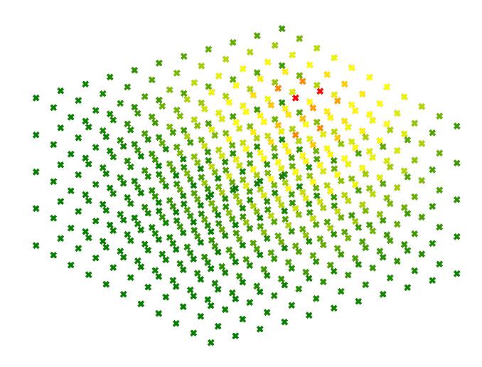
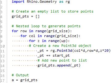
The grasshopper code contains 4 parts in total. Firstly, the creation of the curves, followed by the generation of the module and scalar field. Lastly, the module combination algorithm is applied.

<Introduction to Design Computation> <The Computational Artefact>
3) COMBINING MODULES
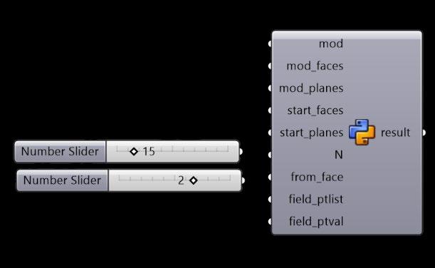
mod = Brep of module
mod_faces = List of module surfaces
mod_planes = List of module planes
start_faces = List of starting geometry surfaces
start_planes = List of starting geometry planes
N = Number of modules to be added
from_face = Index of face to join field_ptlist = List of points in field field_ptval = List of values of points in field
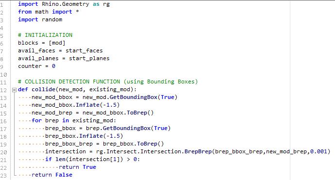
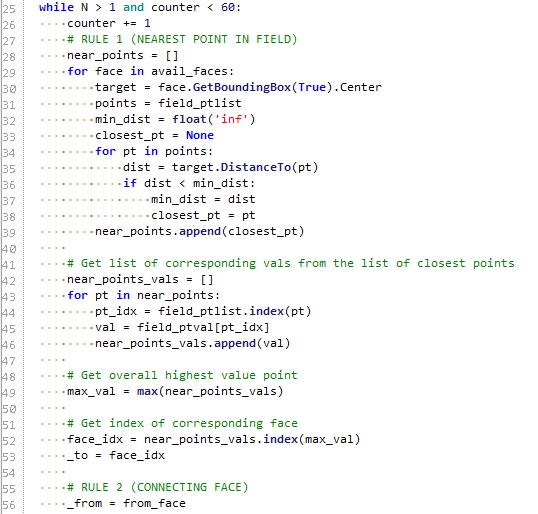
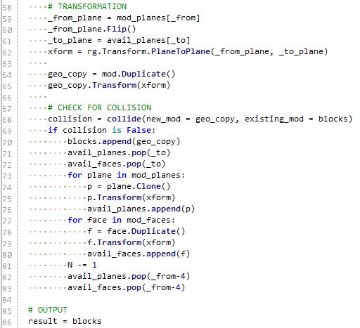
The Grasshopper Python Block takes in surface and plane data from 2A, as well as the list of points and a list of the point values from 2B.

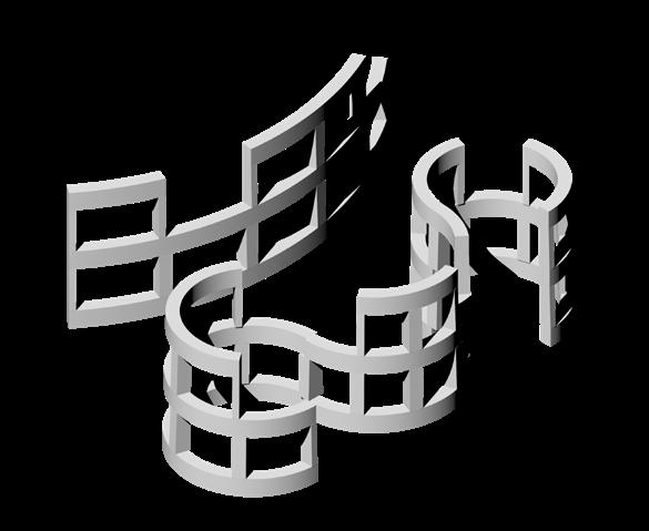
UNDULATE is an exploration of the use of width and height to achieve a sense of movement and dynamism in the space within the building.
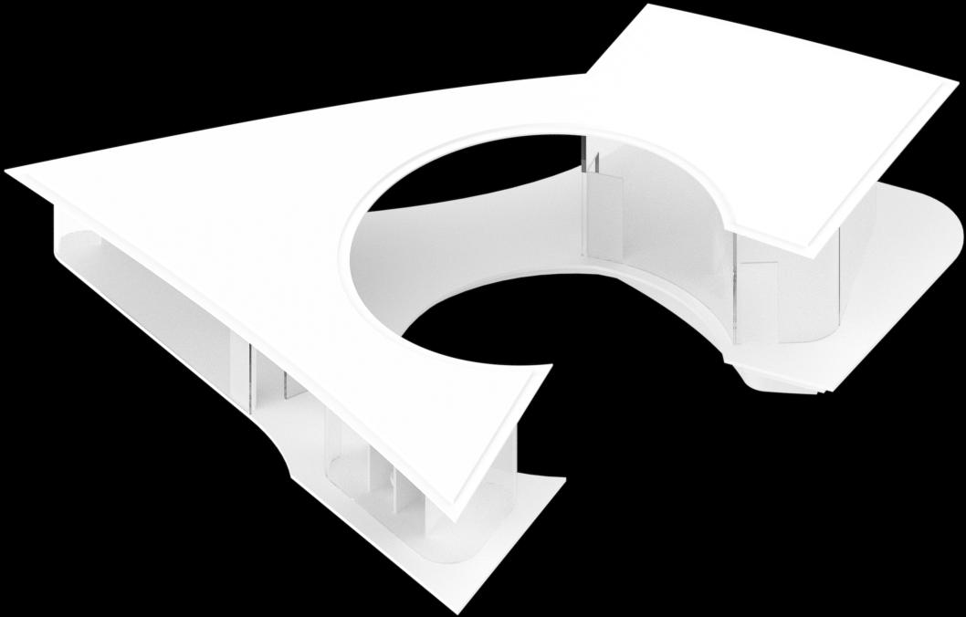
3 Shapes were provided: Circle, Square and Triangle.
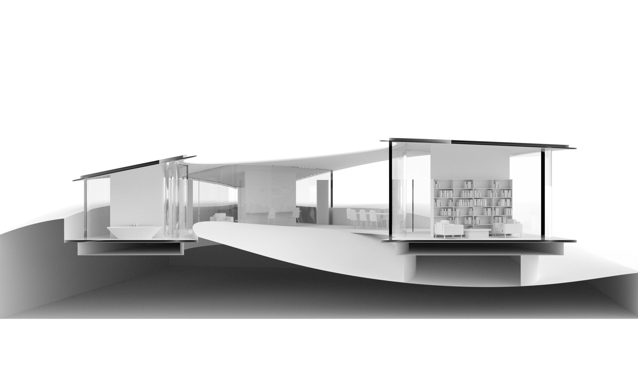
Firstly, I used the circle to subtract away the regions formed by the addition of the triangle and the square, forming narrow and wide spaces that imply functional spaces and spaces that are meant as transitions to one another. As a result of these operations, 3 “nodes” were defined with 2 “links” between them.
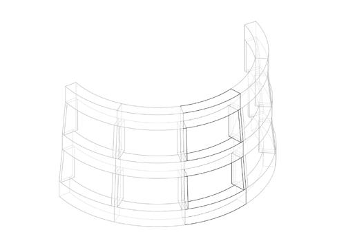
Inspired by the Farnsworth house, full glass walls were used, with furniture surrounding the centre supporting wall in the room. As the building curves towards itself, residents can see across the cottage, making it seem spacious, yet the rooms are placed far apart, creating a sense of privacy. This forms a unique and engaging architectural experience, with its spatial elements dictating the purpose of the spaces within it.
Testing out different configurations and measuring the narrowest and widest space produced
B - BEDROOM
T - TOILET
K - KITCHEN
D - DINING AREA
L - LIVING ROOM
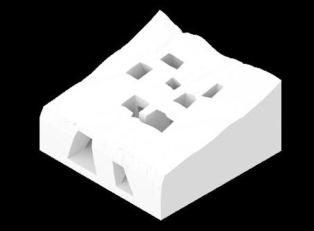
GEOMETRIC OPERATION ITERATIONS
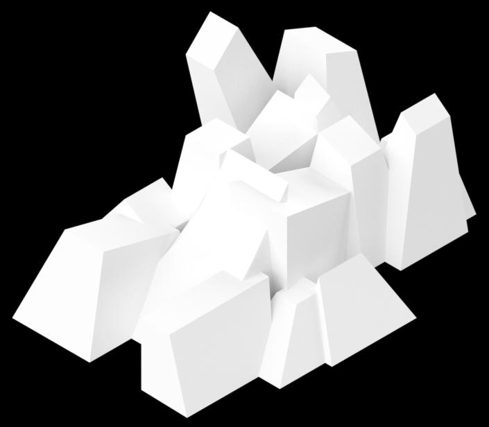
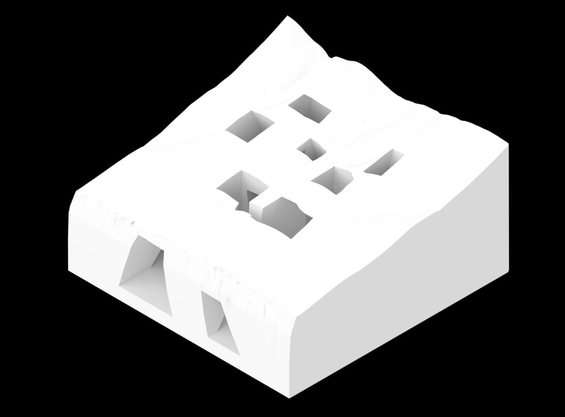
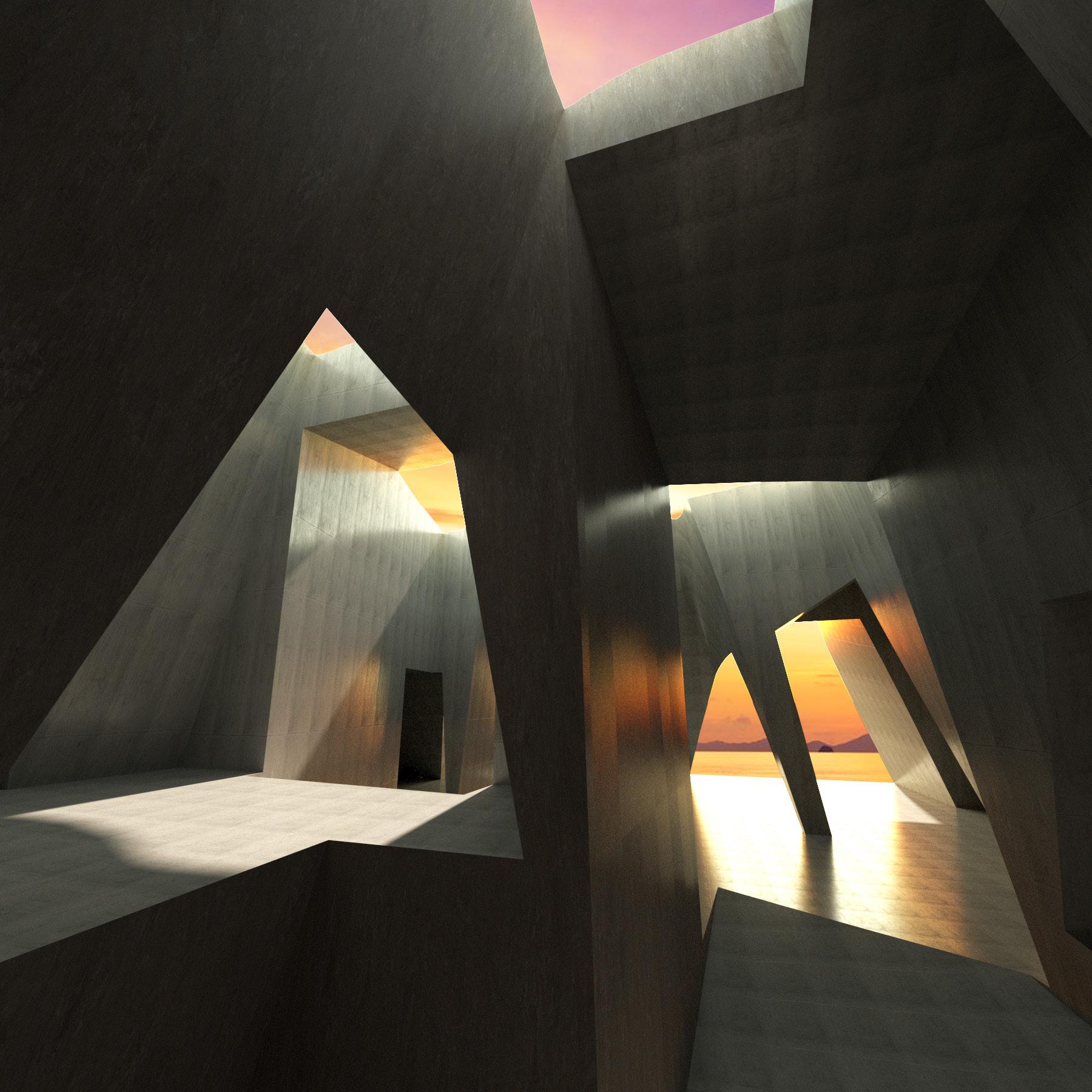
SKYLIGHT investigates the nature of intersections, producing voids or surfaces depending on the proximity between 2 tapered trapezoidal unit spaces. These trapezoidal units are carefully positioned, with the entire mass treated as a continuous field that connects different areas, creating a sense of fluidity and continuity throughout the space.
Several units extend upwards, producing skylights depending on the connectivity of that area, establishing its function as a public or private area. The public areas are designed to be open and welcoming, with plenty of natural light and communal spaces for gathering and socializing. The private spaces, on the other hand, are more enclosed, providing a sense of privacy and intimacy.
ARTICULATED GROUNDS 20.101 ARCHITECTURE CORE STUDIO 1 > SPRING 2023 > CHRISTINE YOGIAMAN, CARLOS BANON > INDIVIDUAL WORK
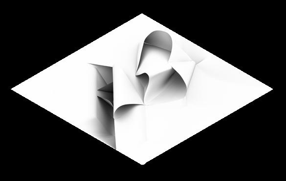
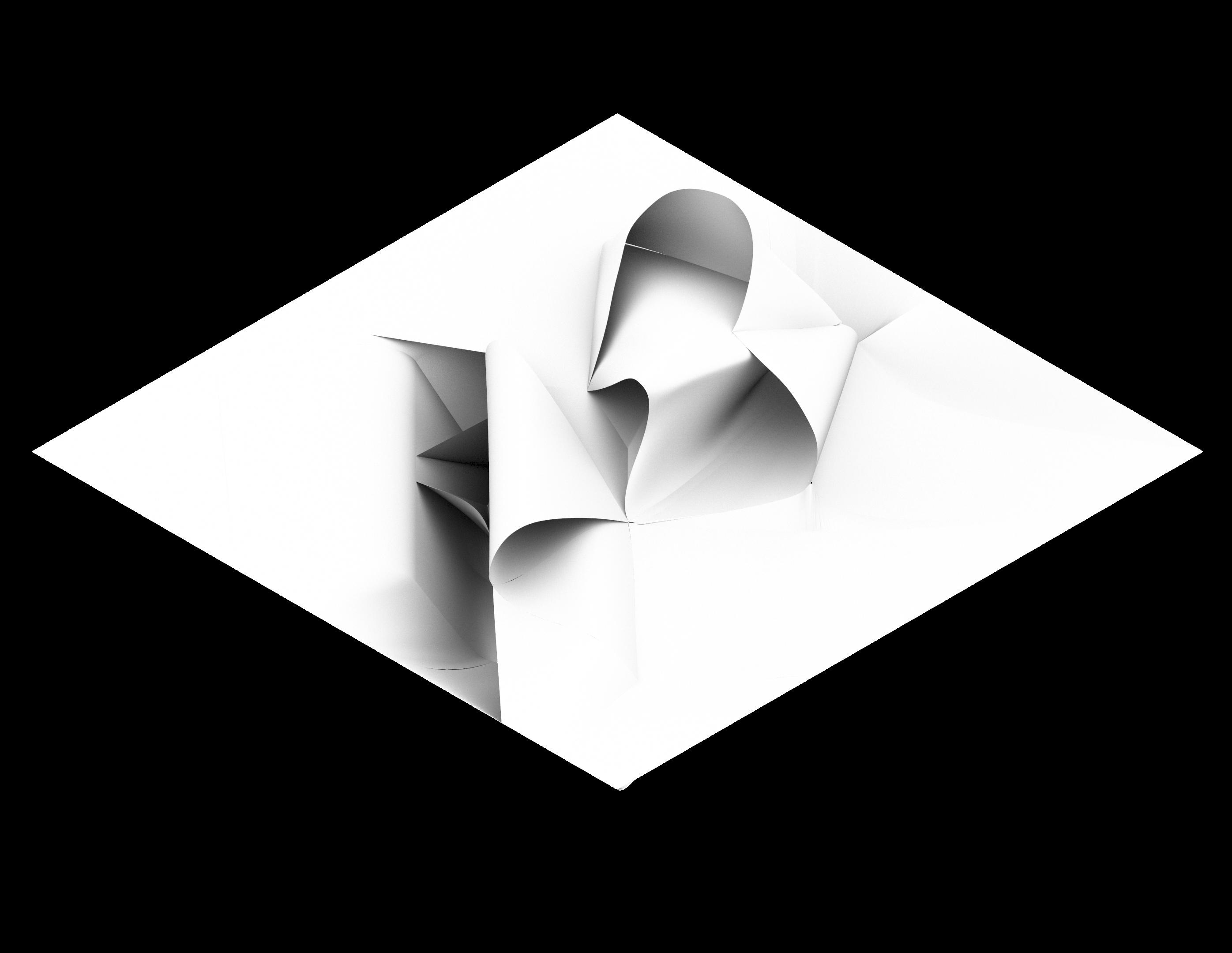
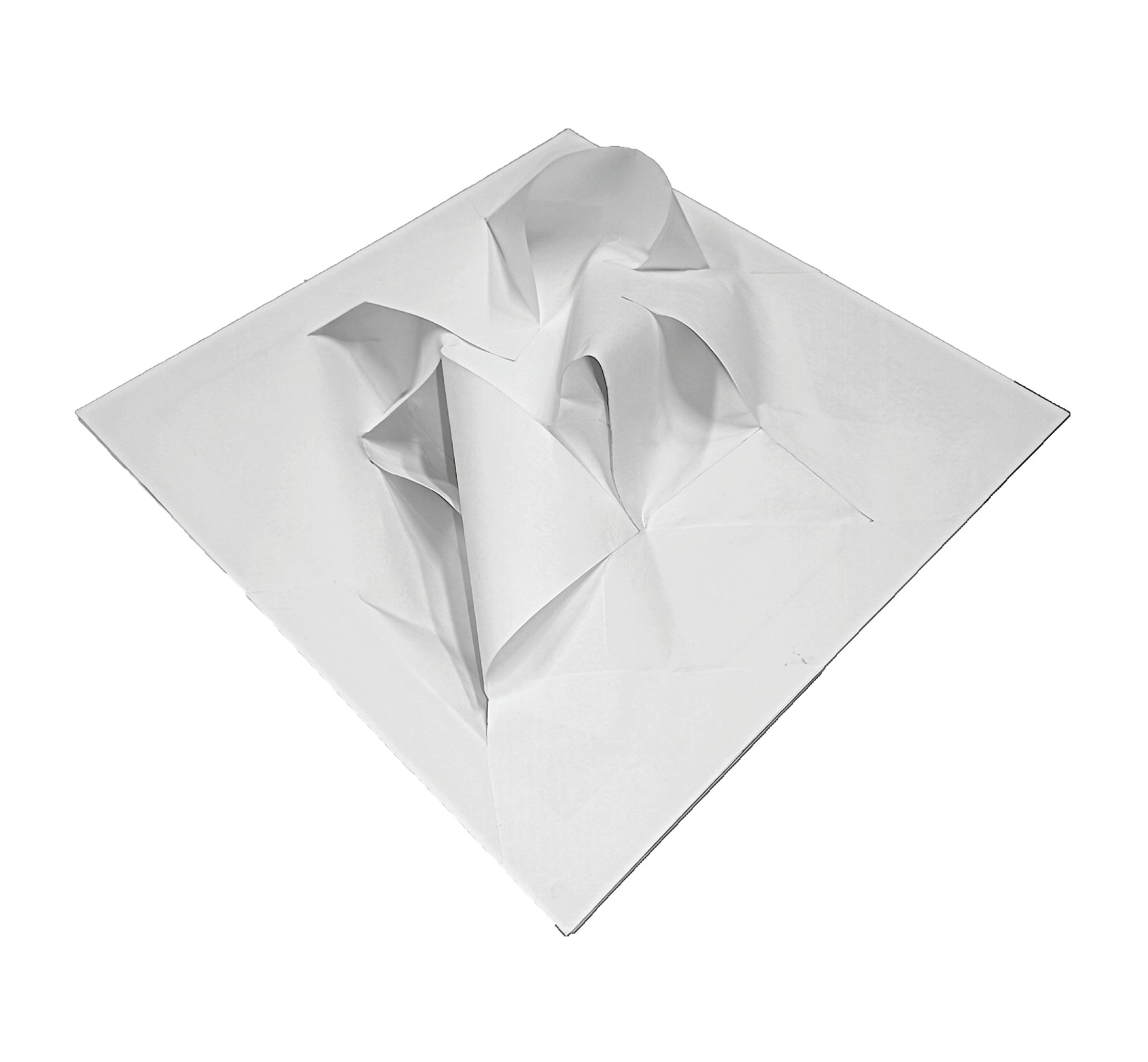
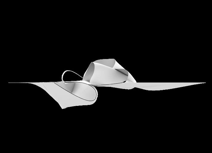
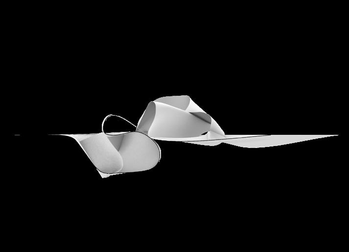
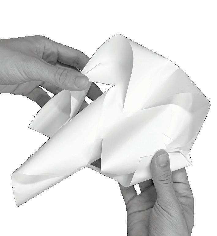
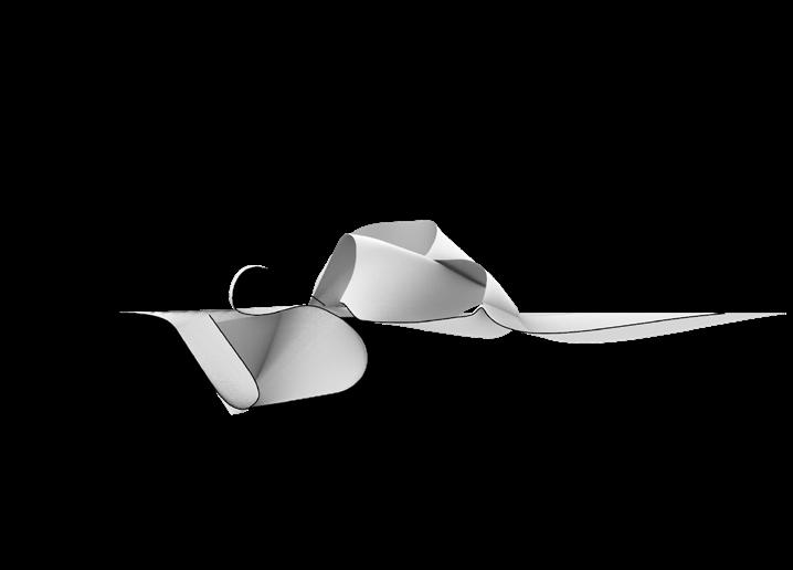
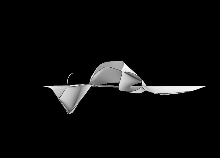
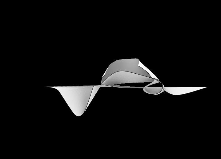
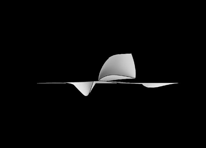
DUNES was formed as a product of the combination of 4 operations: folding, bending, cutting and twisting. This articulated surface performs as a field of transitions between various types of spaces.
The undulating surface, reminiscent of desert dunes, forms a permeable aggregation that burrows and floats through the earth. Vertical extrusions that appear to emerge from the ground create continuity, creating a continuous fabric, yet it delaminates the surface and articulates pockets of space.
With a mix of open and closed spaces, a variety of uses can be accommodated, from public gathering spaces to intimate personal spaces. Pedestrian circulation routes run along the openings to facilitate passage across, or up and down the slopes for vantage points and views of the surface. The diversity of forms and textures creates a fun and interactive environment for the young and old.
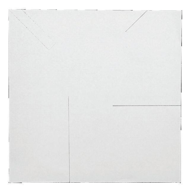
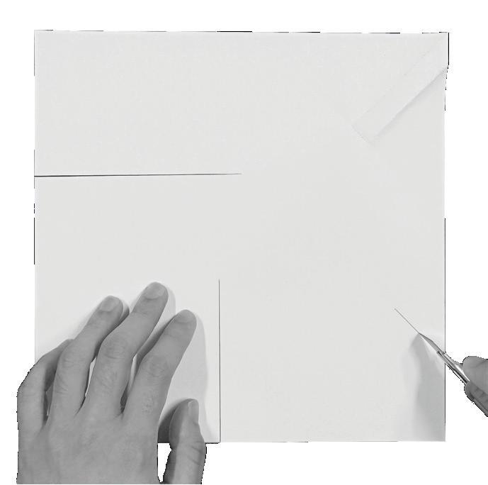
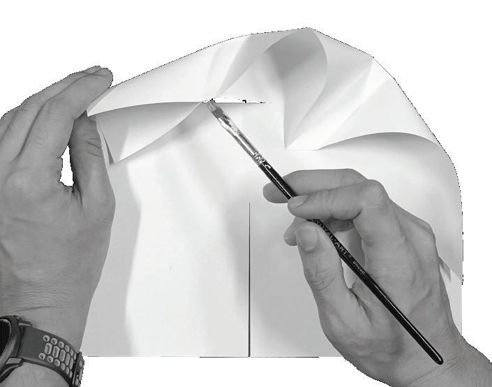
Exploration using 2 methods, namely cutting and bending, in an attempt to hide the edges of the paper
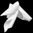
Physical Model
Digital Model
Re-attempted idea of hiding the edges of the paper, but only using 1 method (bending).
Combined “cavities” of different sizes to create irregularity
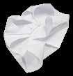
Further explored possibilities of forming such curves and cavities, using small slits along the edge

Looping of edges and connecting them to the main structure, twisting them in various ways to avoid symmetry

Merging of model to a surface of the ground to study its relationship and observe possible
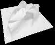


DESIGN PROCESS
Created a frame for the model to be partially submerged into the ground, forming a more continuous surface
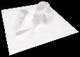
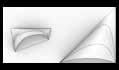
Creation of base unit
Initially used revolve, however this method was limited as it only allowed for the creation of an uniform cavity
Method: drawing out 3-4 curves, which form the cavity, followed by lofting them together Revolve
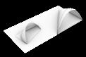
Changing angle of starting curve relative to direction of loft and altering of base curve to create more diverse looking cavities
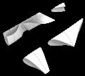
Construction of more elaborate cavities but still using the same method of drawing curves and lofting
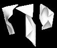

Piecing together individual unit pieces, understanding the geometry of the form
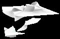
Exploring ways of enclosing spaces that may be more challenging to do on the physical paper. One such area was the gaps in the interior of the model
Usage of MatchSrf and Sweep2 to form smooth transitions
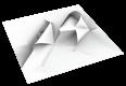
Finalised integration of model into surface, tucking in rough edges and creating a seamless landscape
TANG JIA JUN (1005897) 20.101 CORE STUDIO 1
EX 1: ARTICULATED GROUNDS

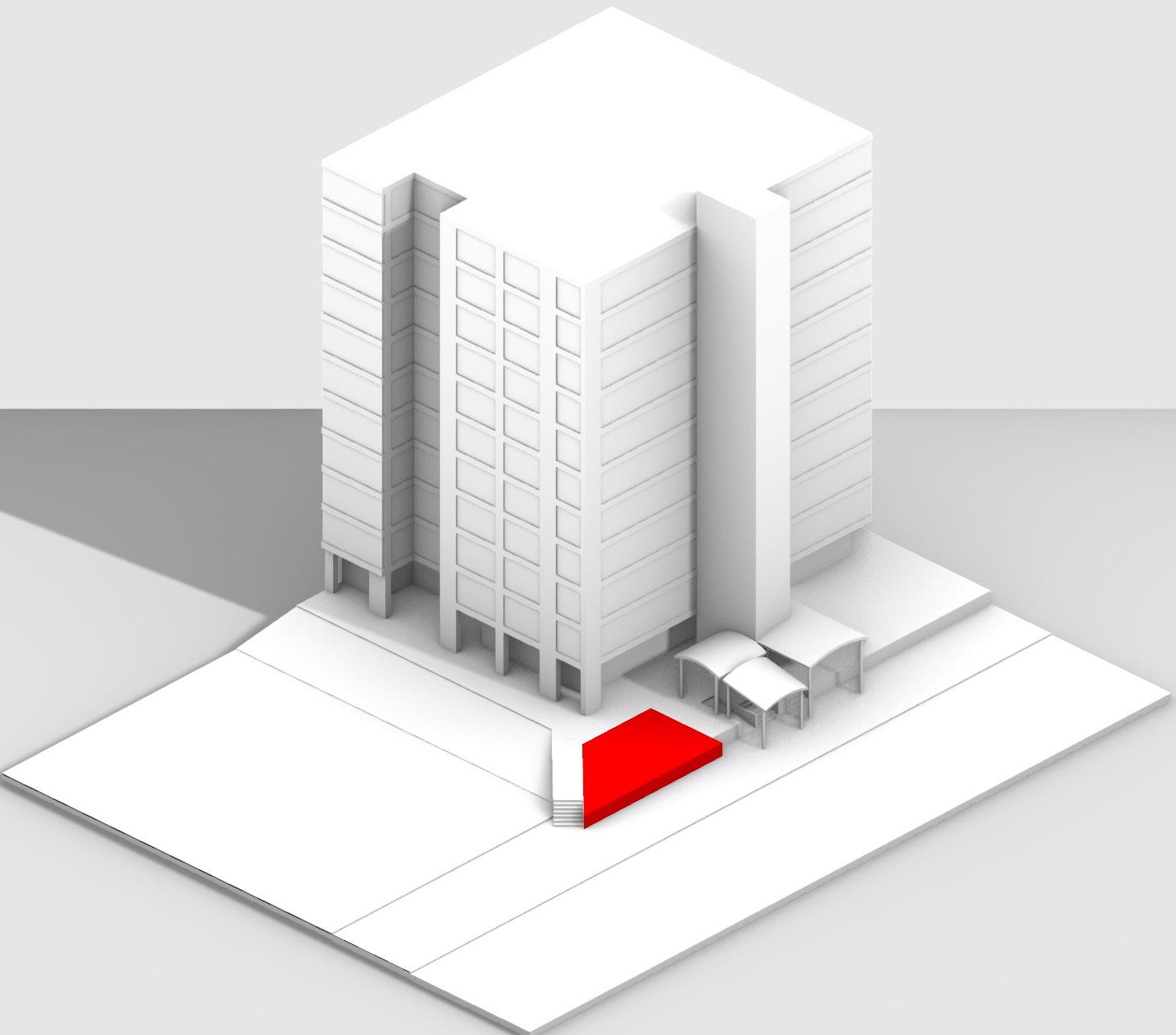
PADDYBUDDIES is a vertical community garden designed to address food security challenges aligned with Singapore’s 2030 goals and contribute to mitigating mental health problems.
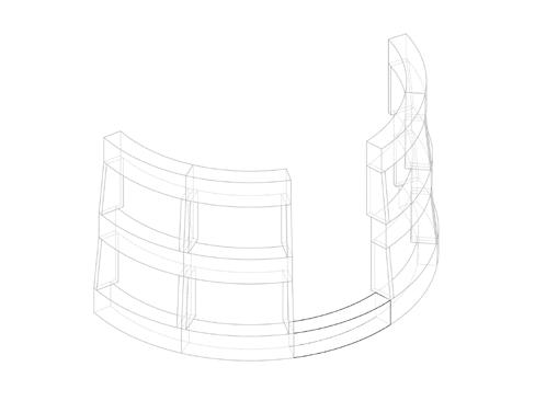
The project’s ethos is to engage the community, engage users in assembly process, and cultivate their garden. These structures shall be conceived as rapidly deployable farming modules that can be installed on HDB’s unprogrammed common spaces.
The design was influenced by the forms of paddy fields and Golden Mile Shopping Centre, where we wanted to create staggered tiered surfaces for the plants, so as to maximise the use of the floor space as well as maximise the sunlight received by the plants.
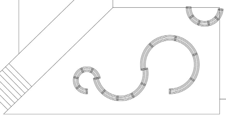
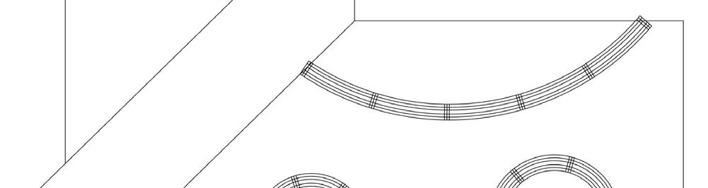
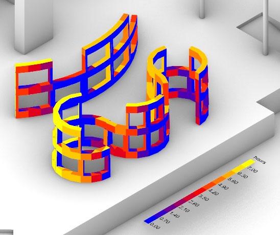
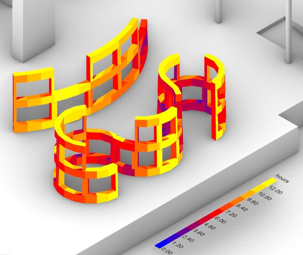
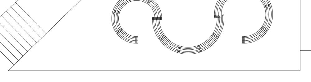
My team identified 2 key narratives which informed us on the shape of our structure as well as its placement in the plan view. Following which, with the application of Ladybug, which is a Grasshopper Plugin that allows for the application of environmental data, we were able to simulate sunlight, allowing us to determine the areas which experience the most sunlight and which areas have the least. From this data, we oriented the structure in a manner to optimise the amount of sunlight received.
For this project, I worked on the form generation using Grasshopper and the physical model .
Our design was our geometric exploration of wireframe models was influenced by stepped silhouettes and organic curves. We extracted the curved geometry and iterated it to generate the surfaces and define spaces.
1.5 PLANT ANALYSIS
1.5 PLANT ANALYSIS
SUNLIGHT EXPOSURE ANALYSIS
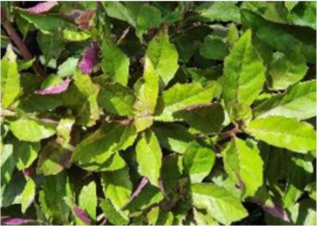
Based on the structural analysis of sunlight exposure and the evaluation of the growing conditions for different types of plants, our team decided that the following plants were the most desirable to be grown in the garden, which are split into 3 to determine the arrangement of the plants, ranging from the areas with greatest to the least sunlight:
We did a sunlight analysis for 2 days, 21 June 2022 and 21 December 2022, where the sun was the strongest and the weakest respectively. In our plant analysis, we noted 3 plants with different growing conditions in terms of sunlight. We evaluated the amount of sunlight exposure at various areas of the model, and concluded that our model was effective in evening out the distribution of the plants, whereby there would not be a case where there is a cluster of the same plant, as shown in the figure above.
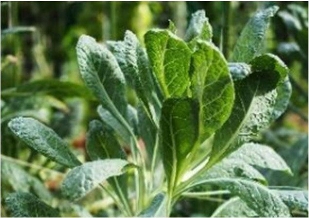
ALLOWING FOR VARIATION IN PLANT DISTRIBUTION KALE
>6 HOURS OF SUNLIGHT
Based on the structural analysis of sunlight evaluation of the growing conditions for different types of plants, our team decided that most desirable to be grown in the garden, which are split into 3 to determine the ranging from the areas with greatest to the least sunlight:
1
Index 1 >6 hours of direct sunlight
Index 2 4‐6 hours of semi‐direct sunlight
Based on the structural analysis of sunlight exposure and the evaluation of the growing conditions for different types of plants, our team decided that the following plants were the most desirable to be grown in the garden, which are split into 3 to determine the arrangement of the plants, ranging from the areas with greatest to the least sunlight:



Index 3 ~4 hours of minimal direct sunlight
OKINAWA SPINACH 4-6 HOURS OF SUNLIGHT
Throughout the year, the areas that are colour‐coded yellow and orange will be populated with the greatest amount of sunlight exposure, which are Kale. This would then be followed by Okinawa purple areas, and Cincau at the blue areas with minimal sunlight exposure. All the plants chosen are of low maintenance, requiring only moderate amounts of water (2 times per week) so that the gardeners do not need to worry the plants frequently. We can then maximize the number grown alleviates the problem of food security.
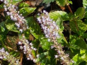
CINCAU
~4 HOURS OF SUNLIGHT
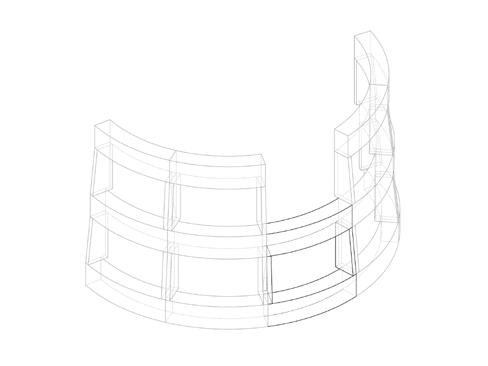
GENERATING OVERALL GEOMETRY
STANDARDIZED VALUES
NUMBER OF SECTIONS (5), SUPPORT WIDTH (0.05), SUPPORT HEIGHT (0.6), CELL HEIGHT (0.3), PERCENTAGE OVERLAP (30%), PATH AMPLITUDE (2)
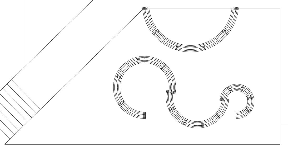
The drawings above were done using Grasshopper, where we first defined the diagonal and boundary paths for the site, which is our design requirement based on the user narratives. The diagonal path is 1.2m wide, and it has a "Path Amplitude" slider to adjust its curvature, while the boundary path is a 1.0m path which is fixed around the perimeter of the site.
Index 1 >6 hours of direct sunlight
Throughout the year, the areas that are will be populated with plants that require the greatest amount of sunlight exposure, then be followed by Okinawa Spinach at the purple areas, and Cincau at the blue exposure. All the plants chosen are of low maintenance, requiring only moderate amounts of water (2 times per week) so that the gardeners do not need to worry about making time to water the plants frequently. We can then maximize the number of plants that can be grown at any period, which alleviates the problem of food security.
PLANTS INDEX 3 CATEGORIES OF SUNLIGHT REQUIREMENT
Index 2 4‐6 hours of semi‐direct sunlight
Index 3 ~4 hours of minimal direct sunlight