
Decomposition & Reorganization
Architecture Portfolio
Boyu Xiao 2022-2025 selected work
Light
Light
Architecture Portfolio
Boyu Xiao 2022-2025 selected work
Light
Light
Location: Corning Museum of Glass, Corning, NY
Instructor: Dr. Masoud Akbarzadeh Website: https://psl.design.upenn.edu/project/ultra-thin-highperformance-glass-bridge/ Main Roles: Formwork, Steps, Support, Assembly Sequence Designer
Fabrication Coordinator
Assembly Manager
Diagrams / Drawing Production
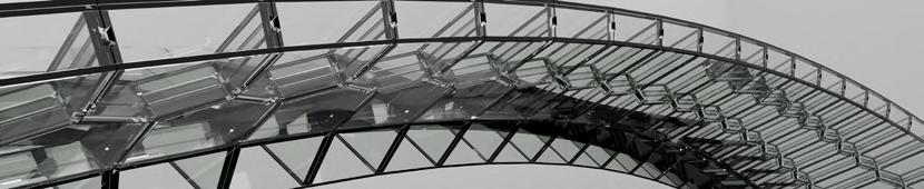
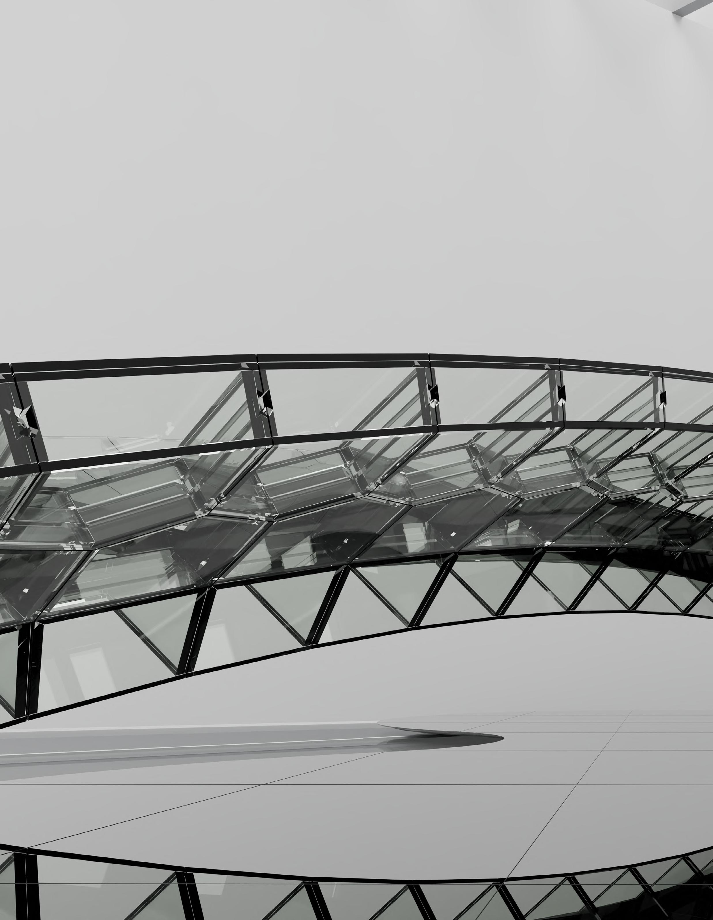
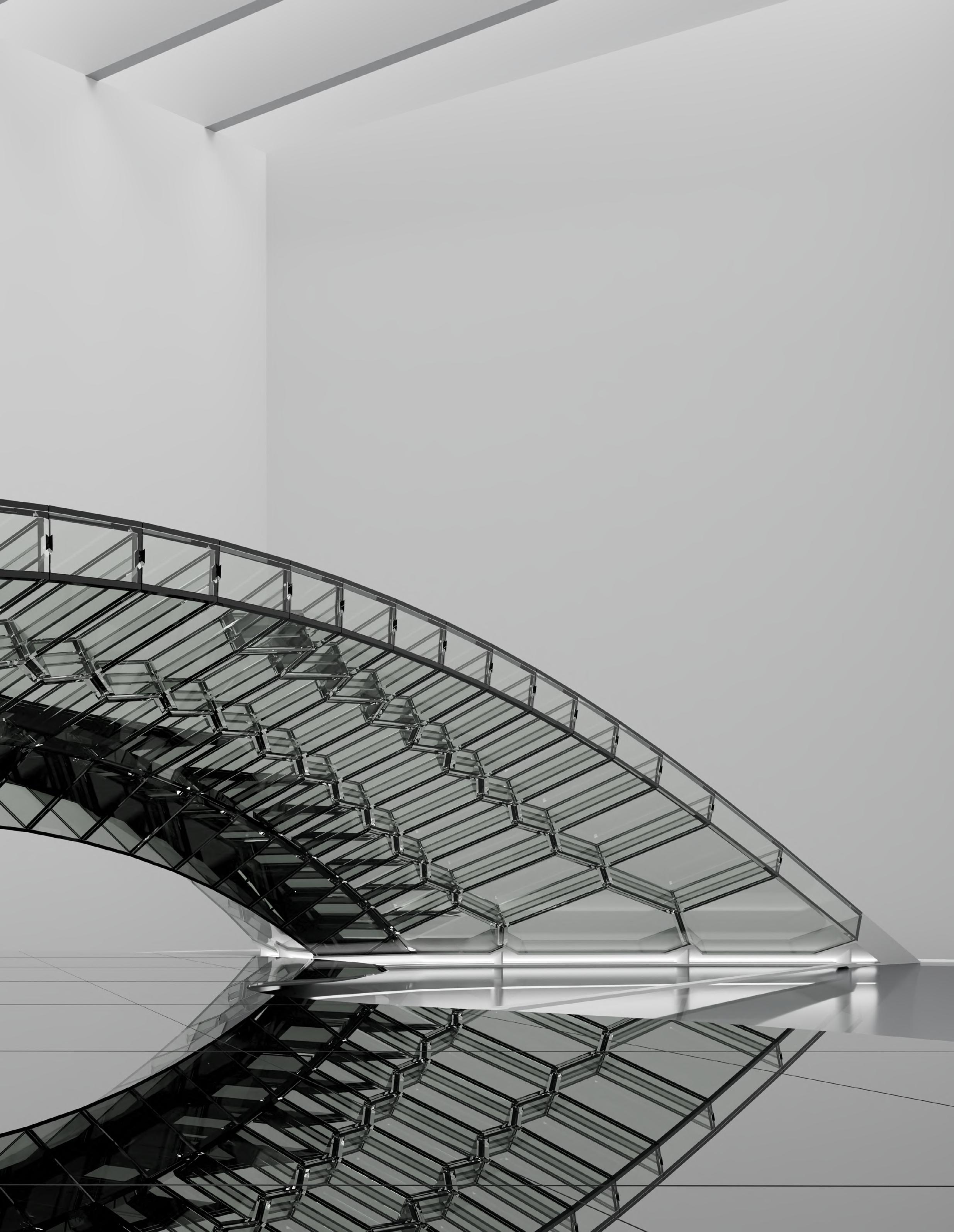
The Penn Monument for Hope is a high-performance transparent glass bridge that symbolizes connection, collaboration, and hope. Bridges are more than functional structures; they represent the human desire to overcome separation and foster unity. This project embodies those ideals through its innovative design and engineering.
The Glass Bridge is a light weight, sheet based structure with compression-dominant forces. Utilizing Polyhedral Graphic Statics, the design achieves a funicular form (tension / compression only) with minimal mass and optimal structural efficiency. PSL has developed their own software program, Polyframe 2, to create the 3D geometry of the bridge in the form of a compression-dominant structure.
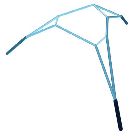
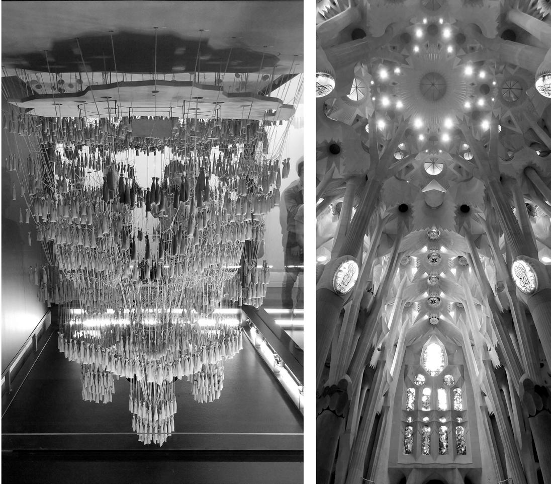
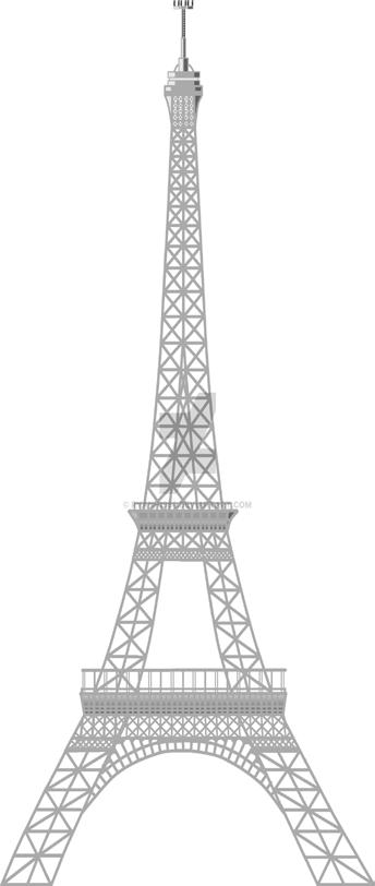
Many architects and master builders used hanging-chain models to design the tension-only and compression-only forms of their structures. Antoni Gaudí (Spanish, 1852–1926) used extensive, physical techniques to find funicular forms for the Basílica de la Sagrada Família. However, hanging chains is not the only way to find such geometry. There are geometric methods to find such forms as well. Maurice Koechlin (French Swiss, 1856 –1946), who designed the Eiffel tower, used the geometry-based method of Graphical Statics to find the funicular form of the tower under lateral wind loads.
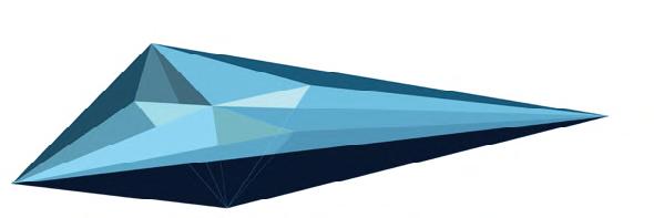
In Polyhedral Graphic Statics, the force diagram consists of closed polyhedrons with planar faces, where the area of each face represents the magnitude of the force in the member of the structure. The form diagram also consists of planar faces, and these planar diagrams can be used to design efficient and lightweight thin-sheet building components.
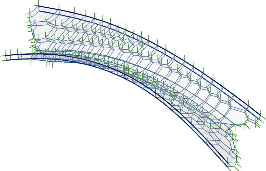
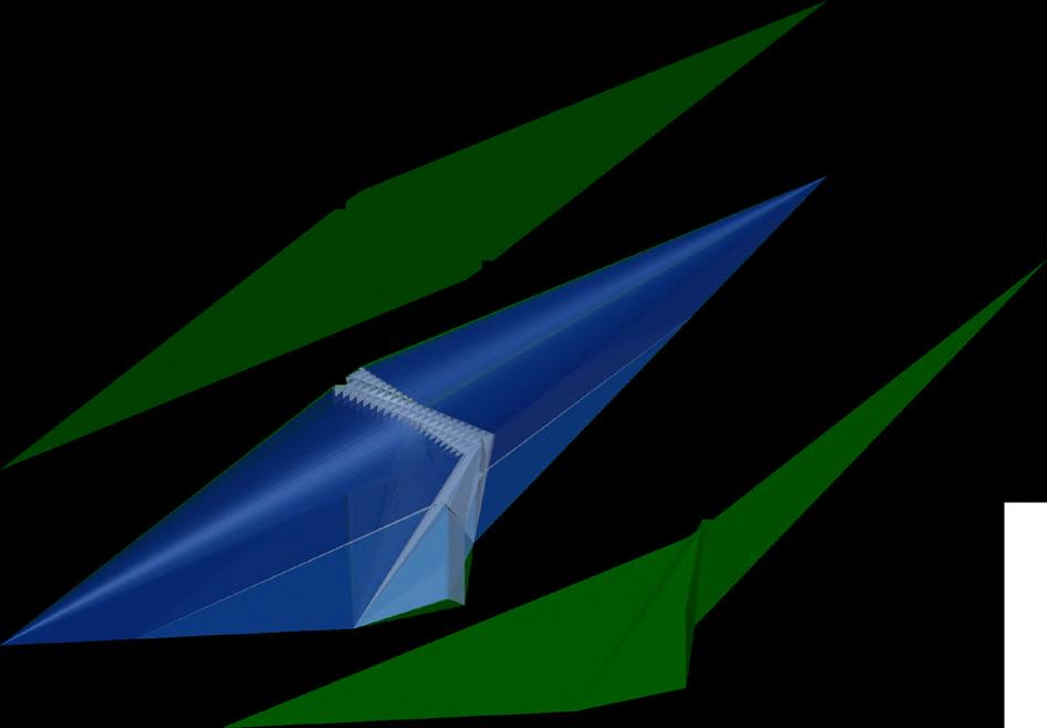
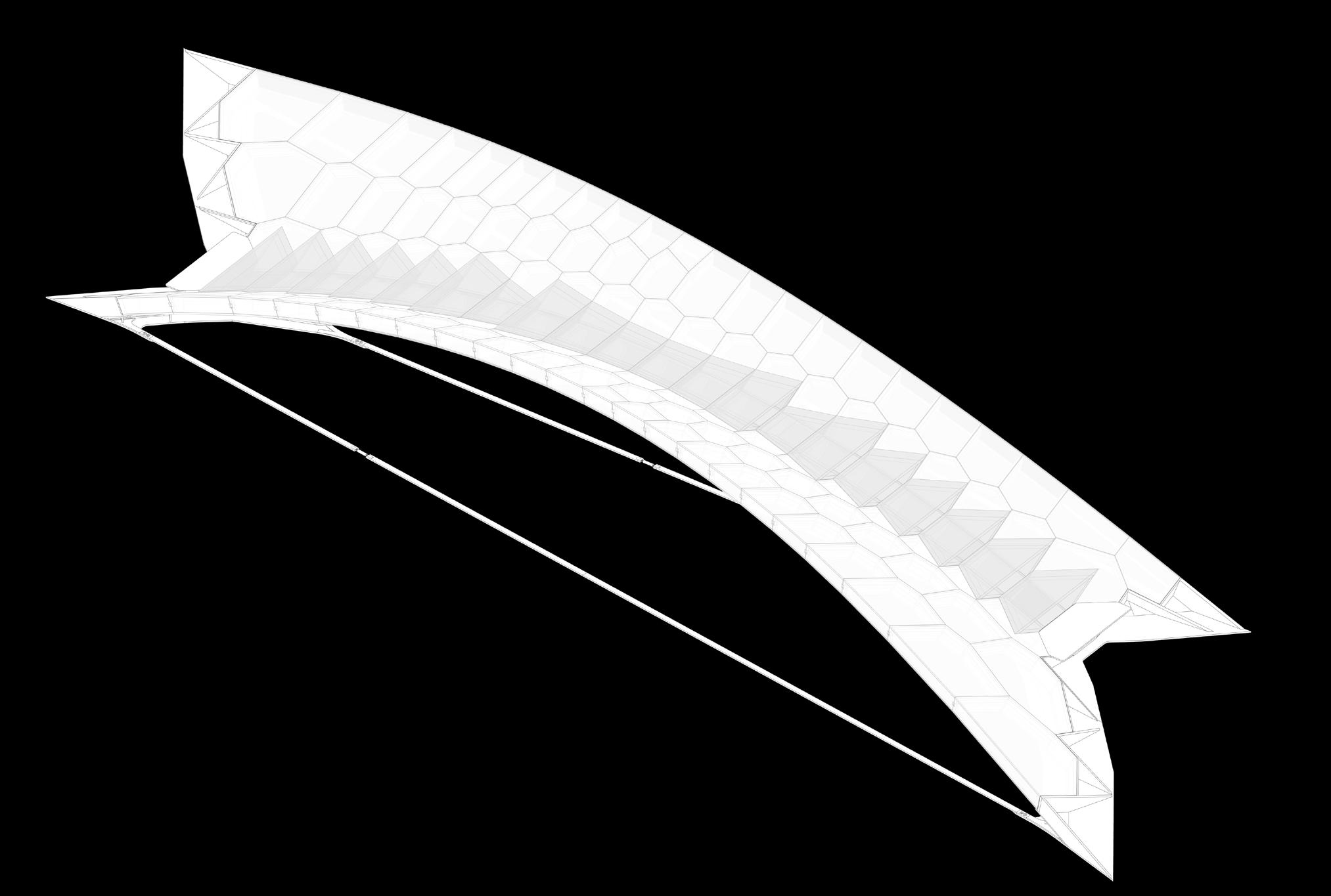
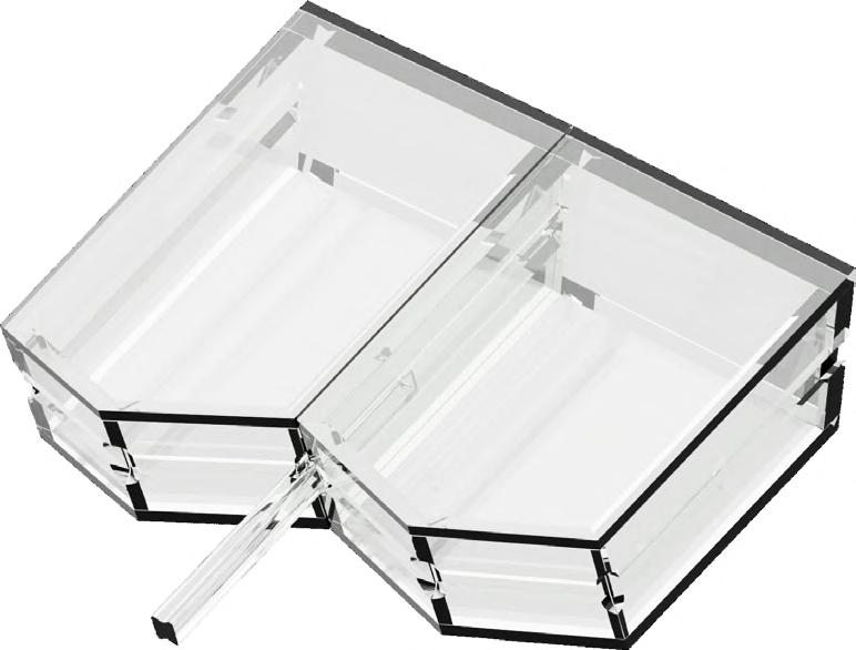
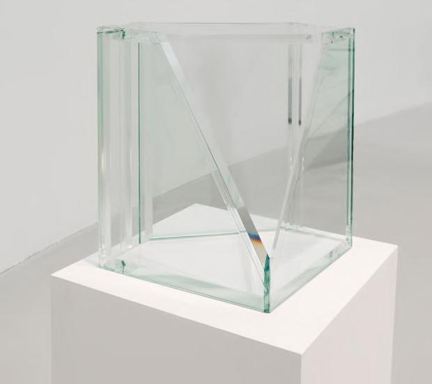
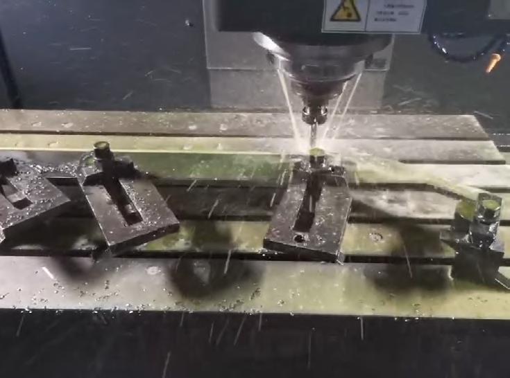
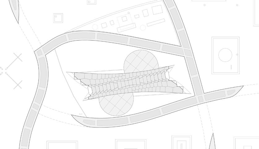
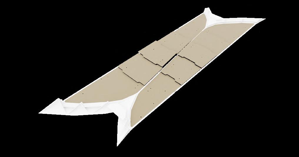
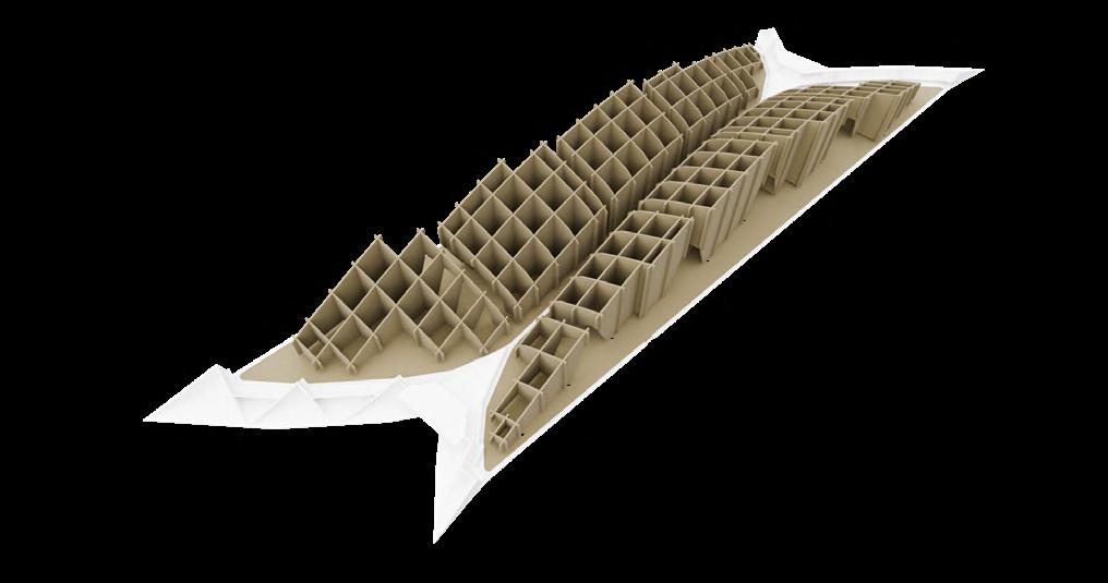
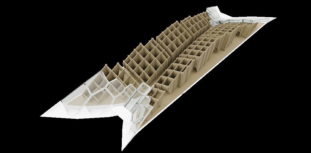
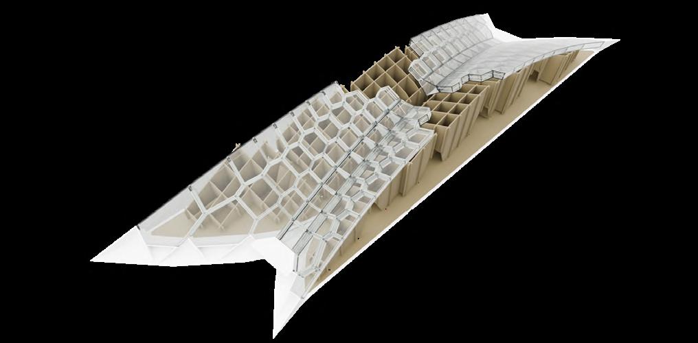
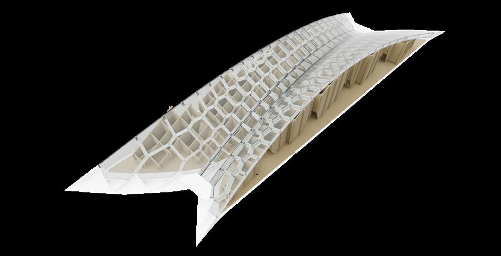
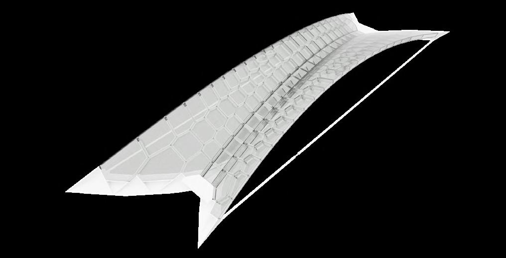
The modular bridge is composed of 124 hollow glass units (HGUs) that span 10 m from the supports. Each HGU is a closed polyhedron with flat faces. Every HGU includes laminated glass panels on the top and bottom and acrylic side plates for ease of fabrication. The glass panels are 16 mm thick, while the acrylic sides are 21 mm. Precision milling shapes all components, with 5-axis milling used for the acrylic parts to create complex butterfly connections.
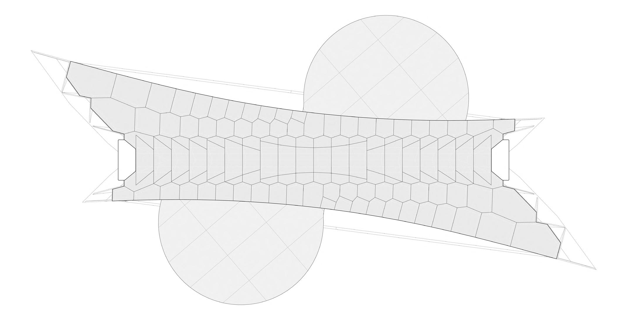

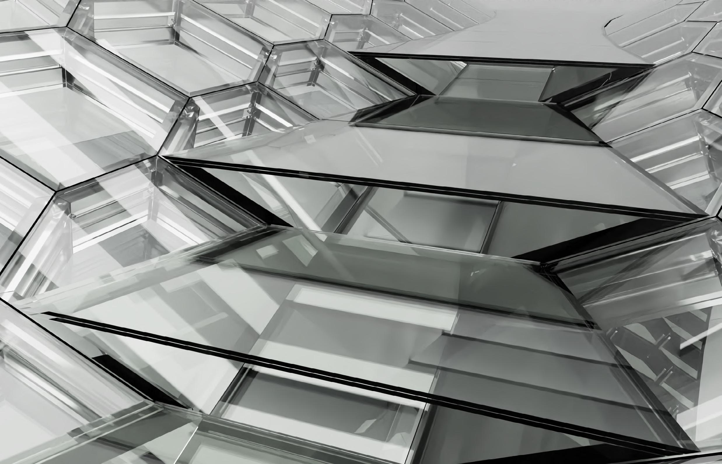
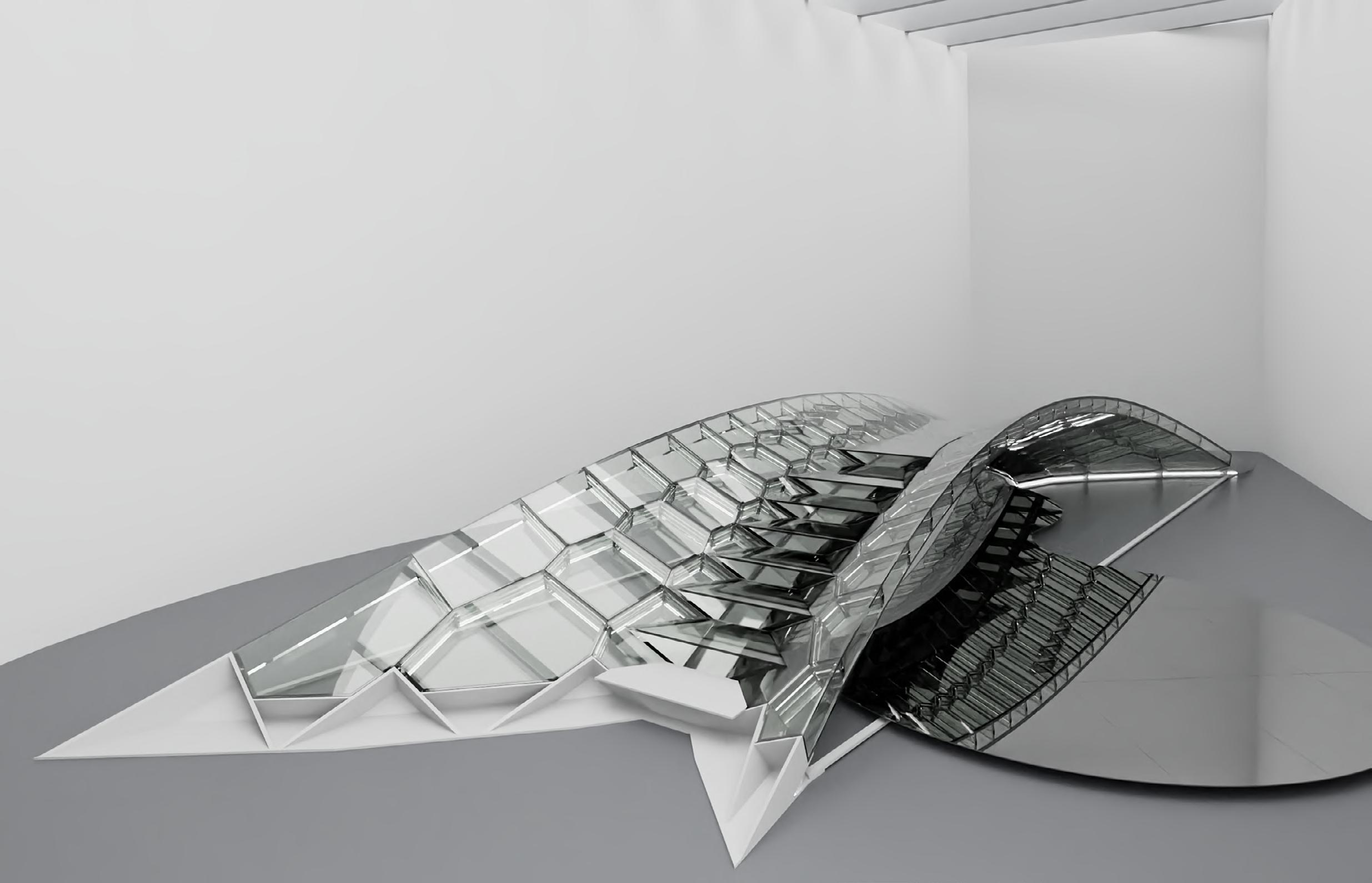
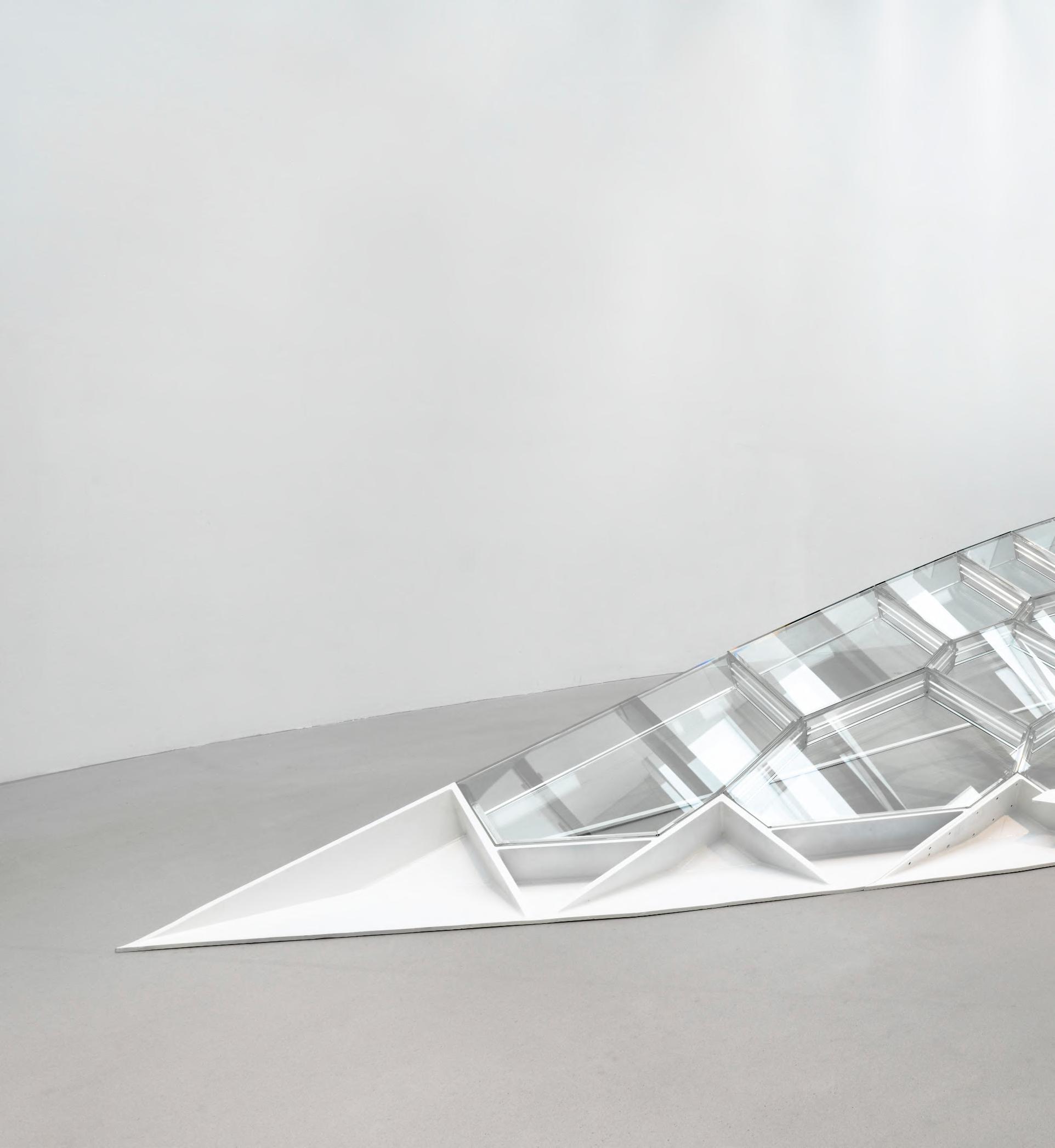
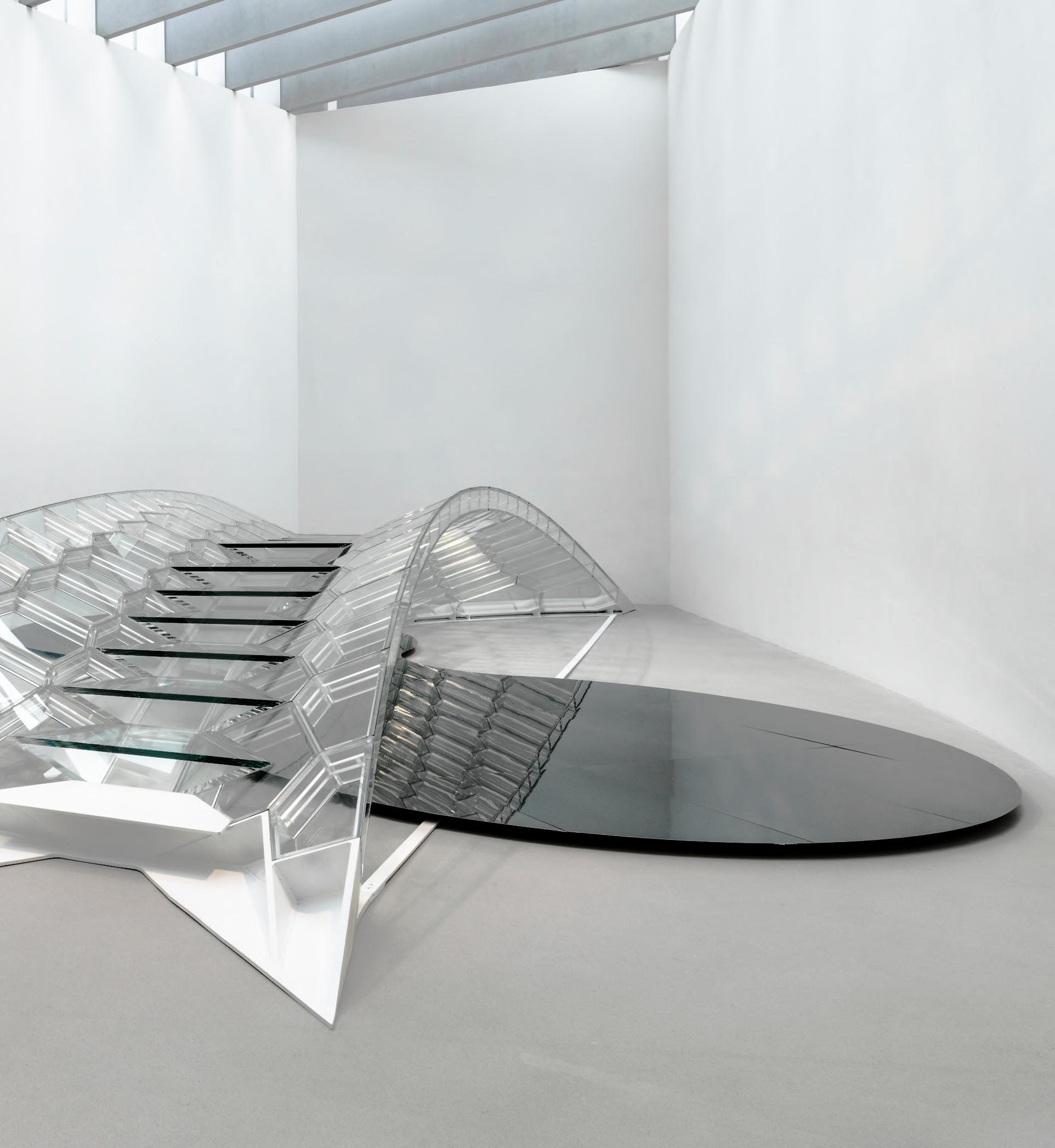
The HGUs interlock through a butterfly-shaped locking strip that fits into pocket channels on adjacent units. To avoid damaging glass-on-glass contact, a soft, transparent interface material—SentryGlas™—is placed at joint interfaces.
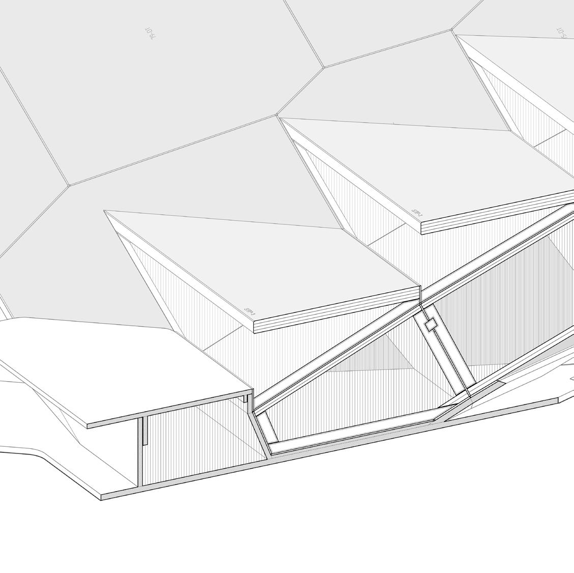
Detail Section 1
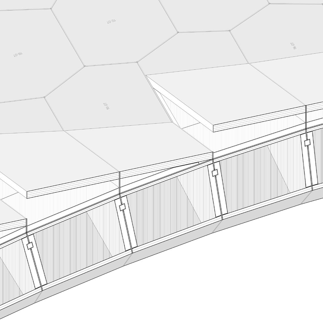
Section 2
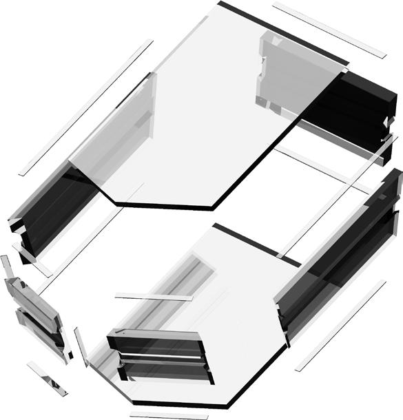
Exploded HGU
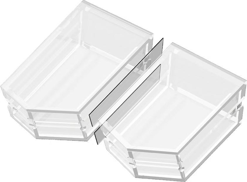
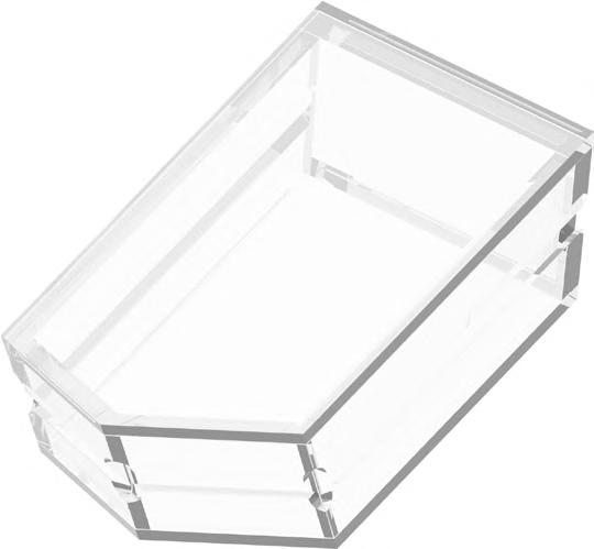
Assembled HGU
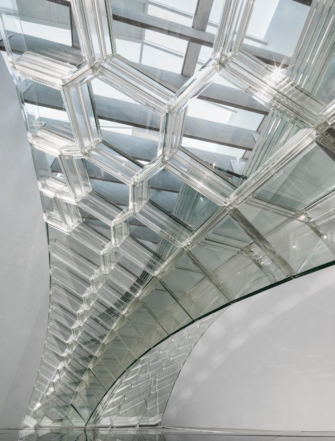
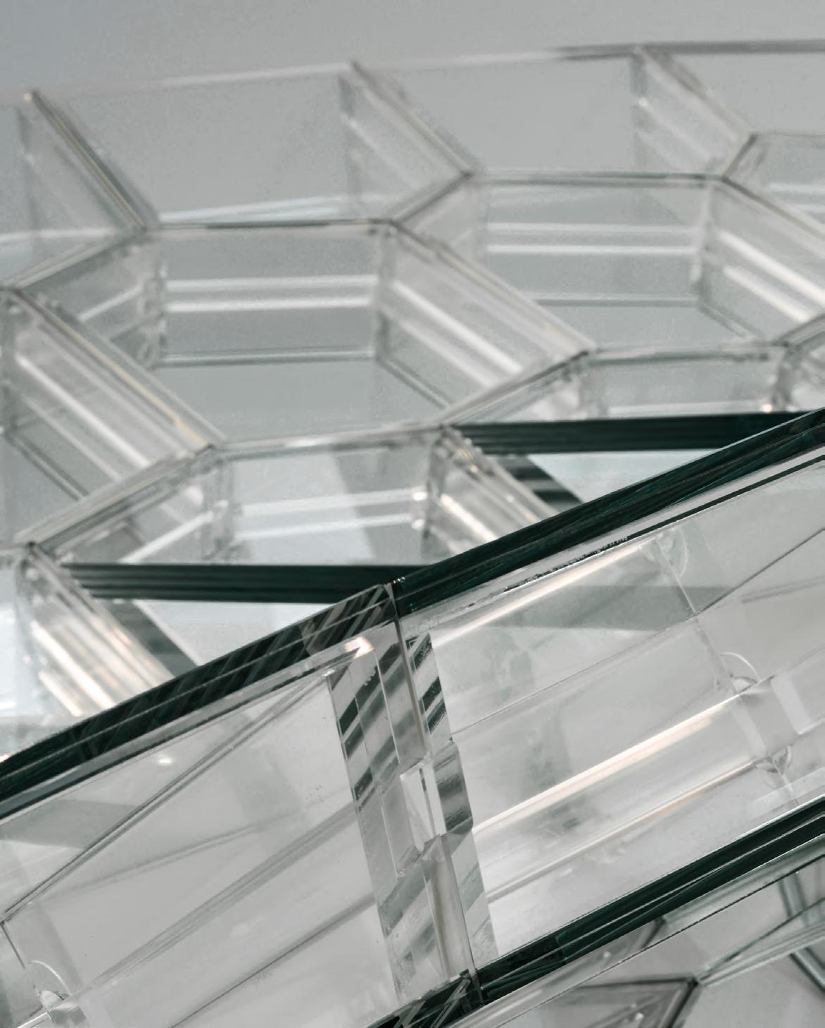
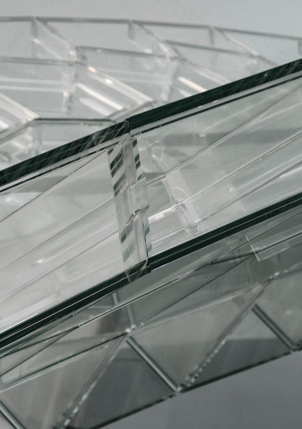
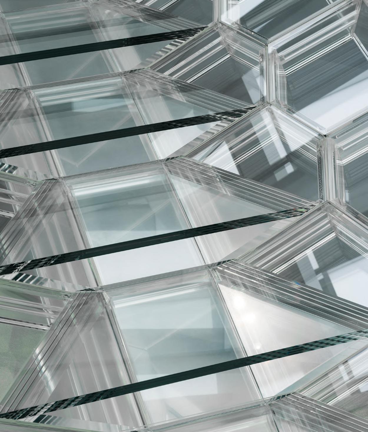
The success of building the glass bridge highly relies on the precision of fabrication and assembly. To achieve this degree of accuracy, the team collaborated with several firms from Germany and China. There was many back and forward works happened during the fabrication process to guaruntee the glass and metal parts are within tolerence.
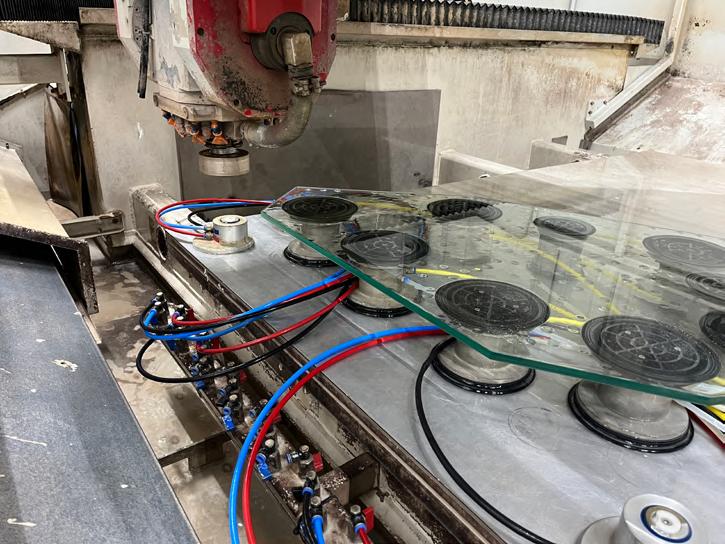
Manufacturers

Fabricators





Assembly
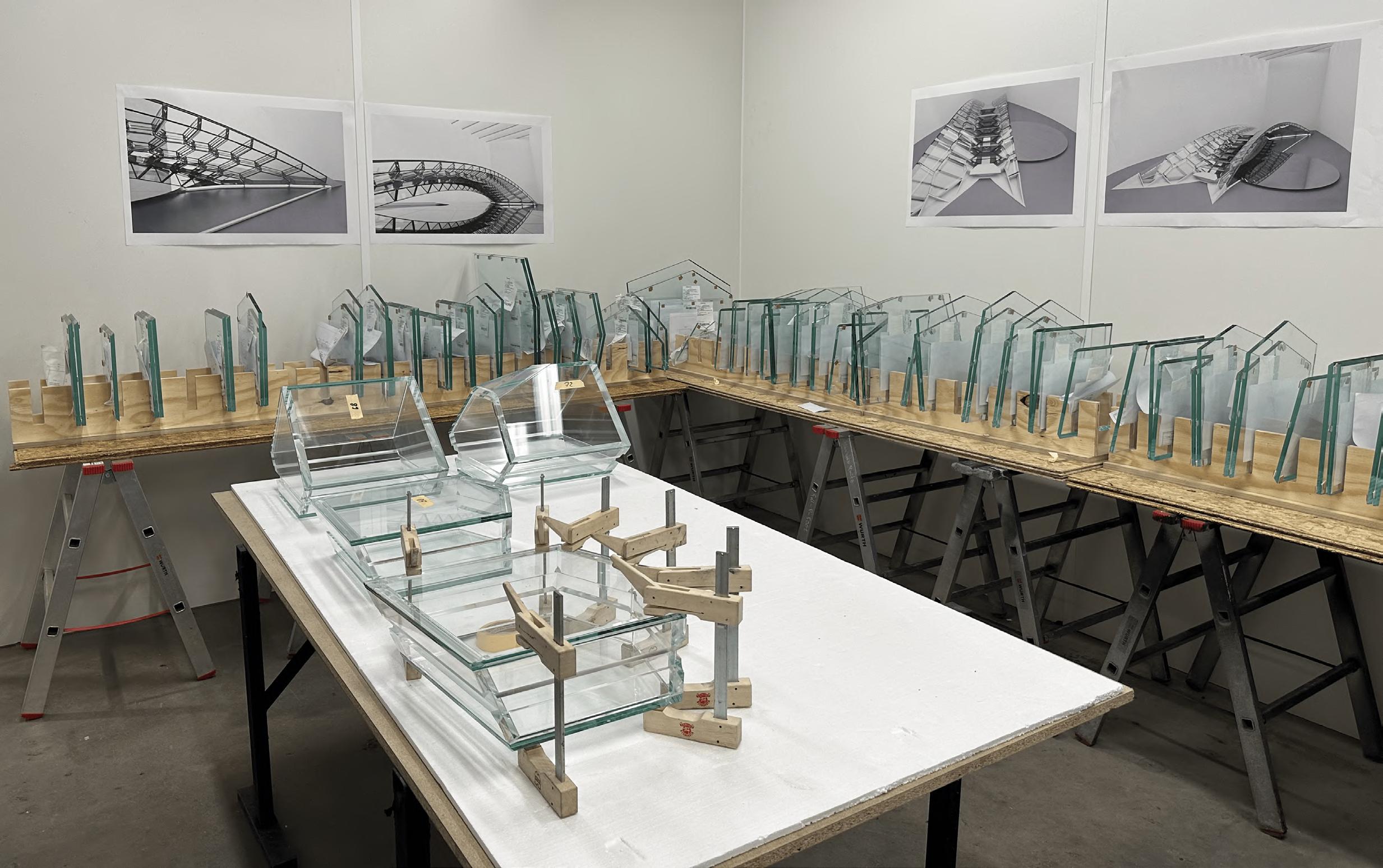
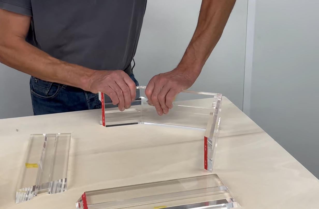
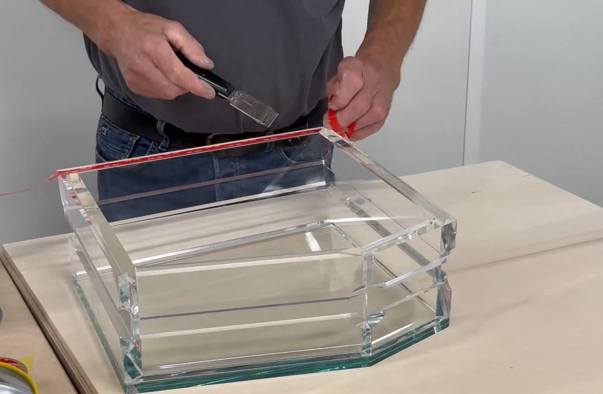
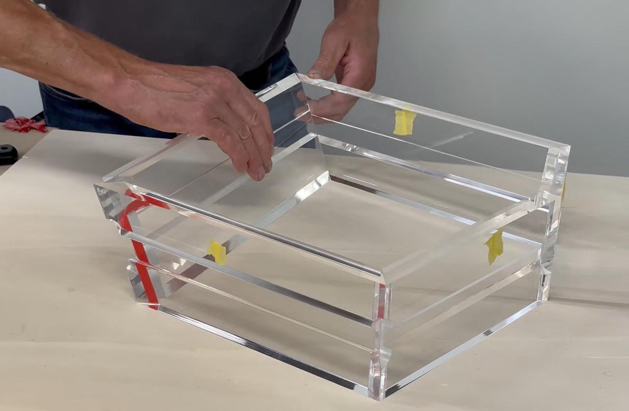
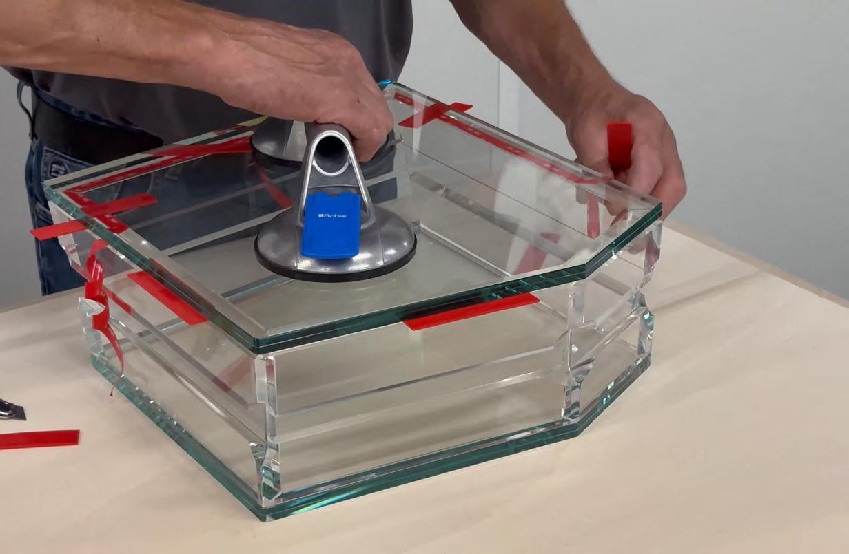
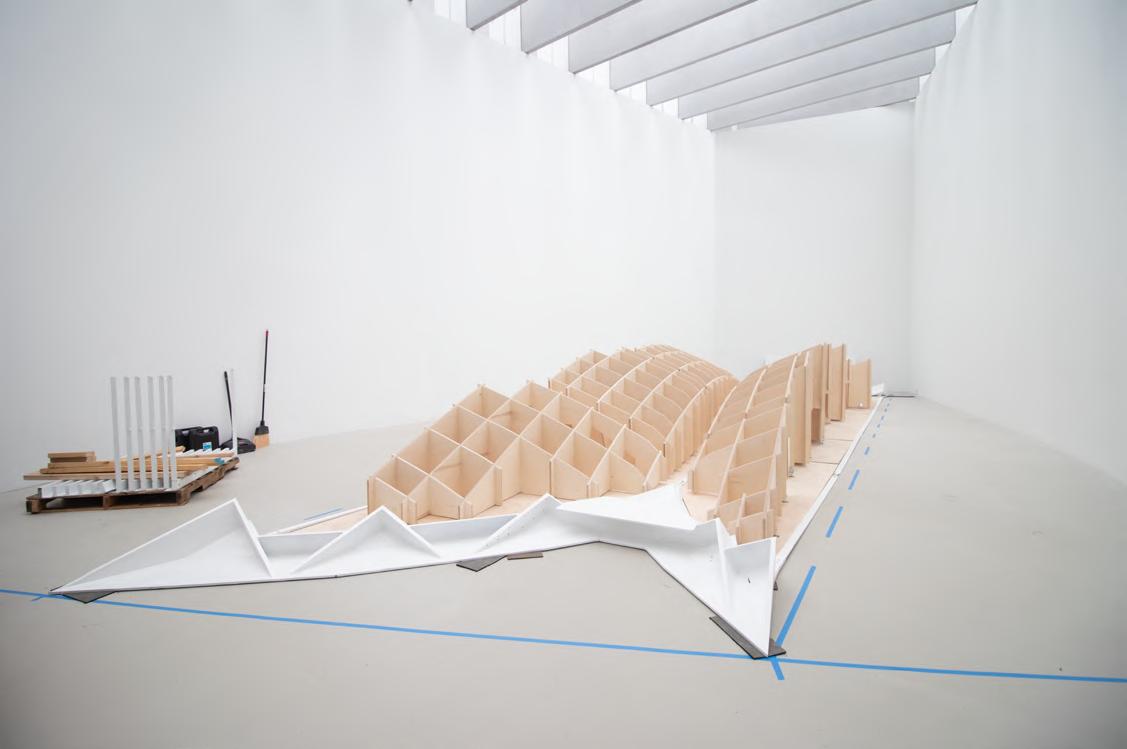
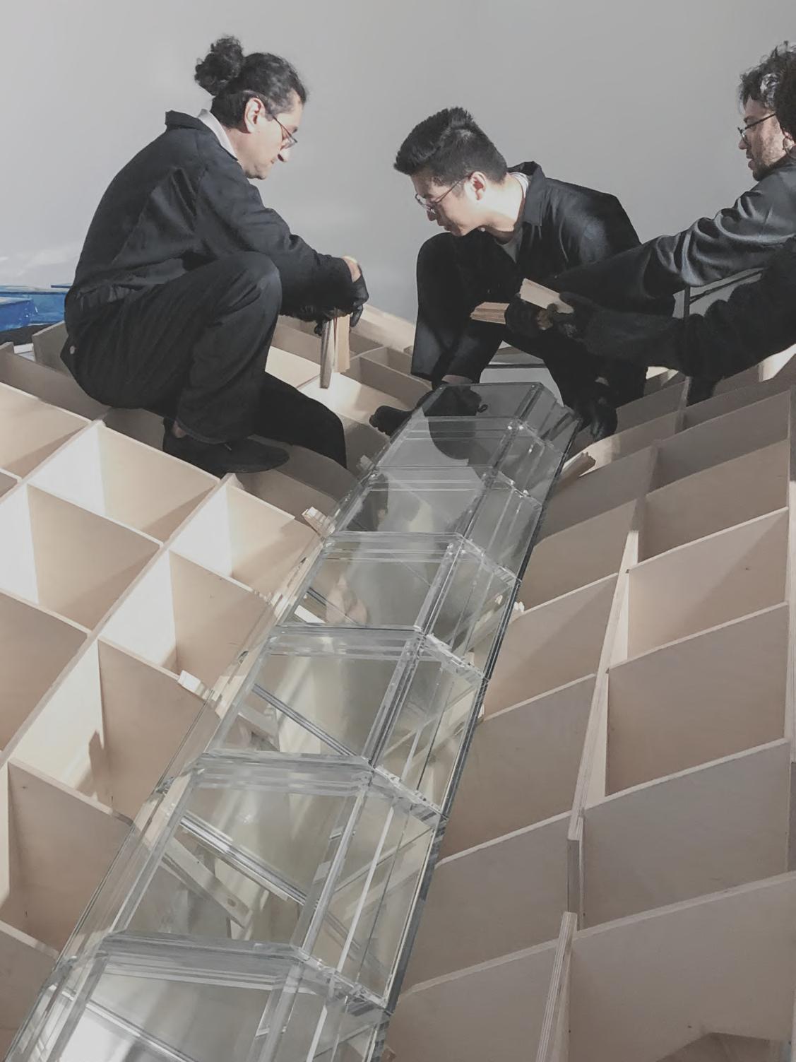
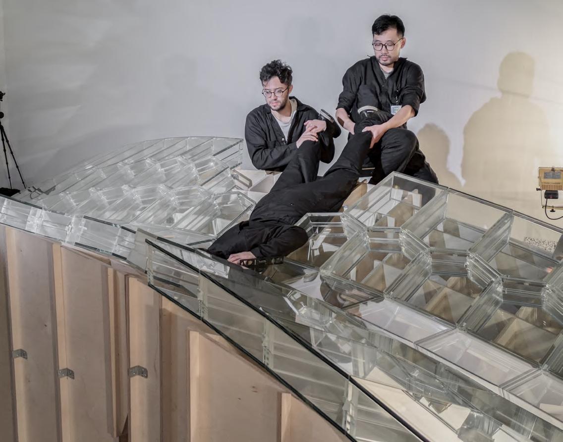
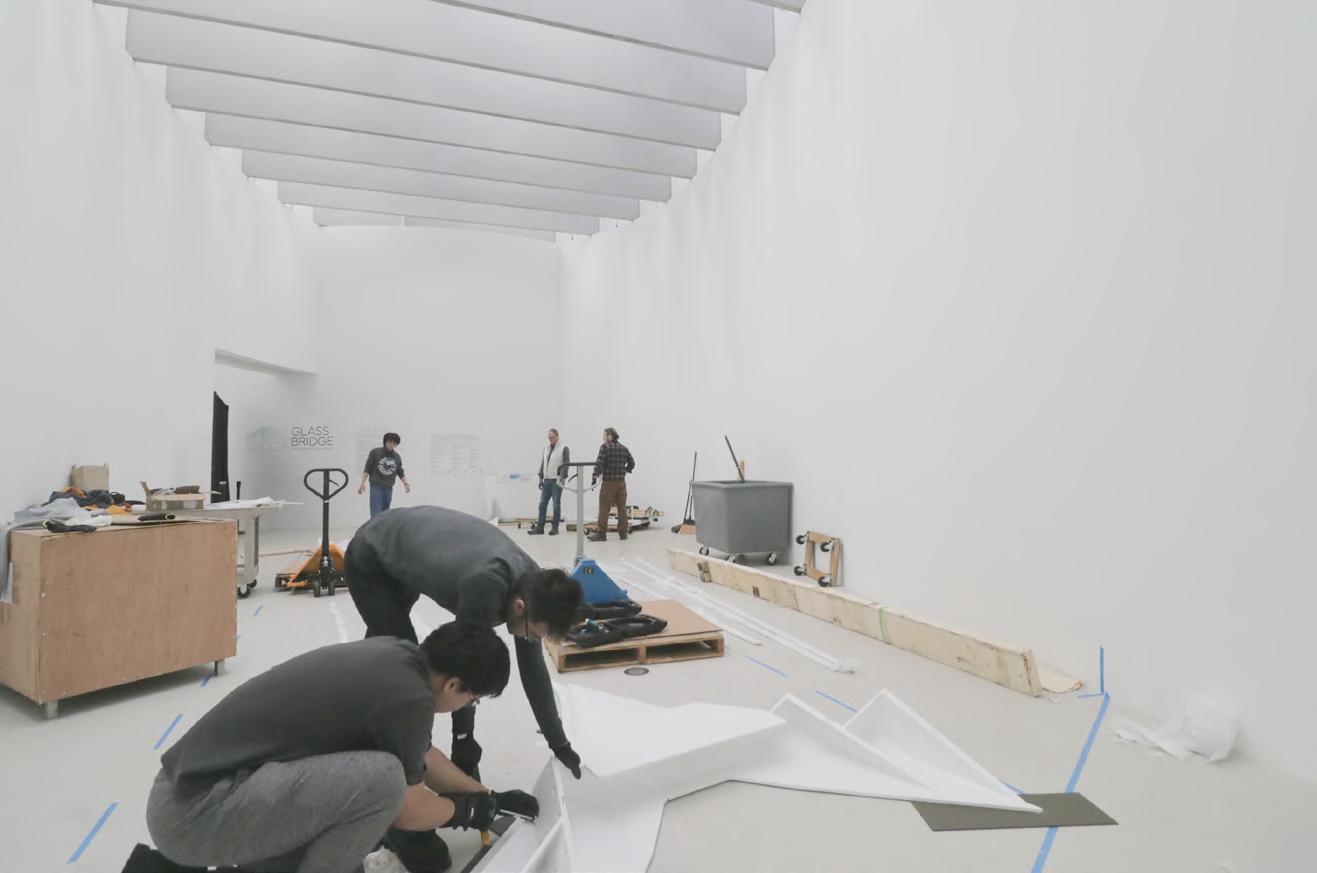
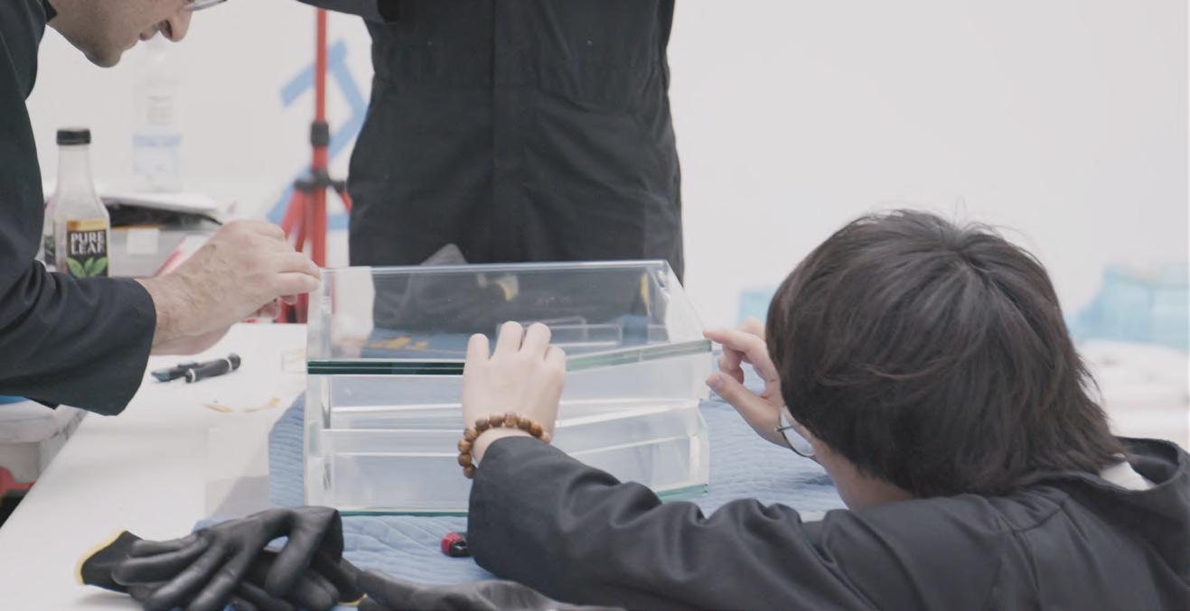
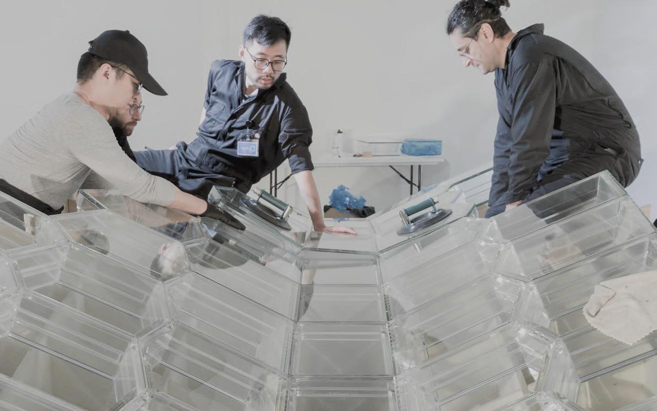
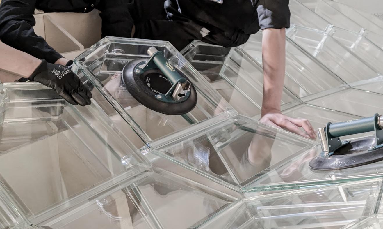
The assembly starts from placing the steel supports in the exact locations required for completing the arch in the gallery space. The bridge has a rotation symmetry, which allows the construction to start from both ends and continue until the HGUs meet in the middle. This also means that placement of the supports is crucial—any rotation or misplacement will be transferred to the arch of the bridge and keep the units from meeting exactly.
Location: N/A
Instructor: Masoud Akbarzadeh
Team Member: Yuhang Tao, Boyu Xiao
In the world of architecture, higher structural efficiency has always been a goal for aengineers and architects, which means more loads witch less material. However, a structure system that can benefit a wide range of the architecture industry is not only about structural efficiency, but also the economic cost and accessibility of the materials consumed, the accessibility of the tools used in the fabrication, the time cost of fabrication, and so on.
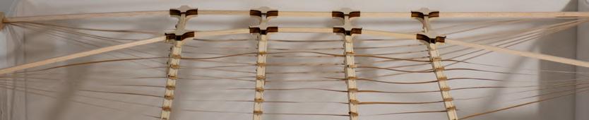
Under this environment, traditional building materials such as bamboo and wood are beginning to regain designer’s attention, because they are environmentally friendly, easy to work with and less expensive. In this study, we use 3D graphic statics as a tool to design a structure system that can take advantage of the tensile capacity of fibrous material. The purpose is to create a system with high structural efficiency, but also with low material and manufacturing costs. At the same time, parameterize the design process so that it can be easily adapted to different architectural needs by just adjusting a few numbers.
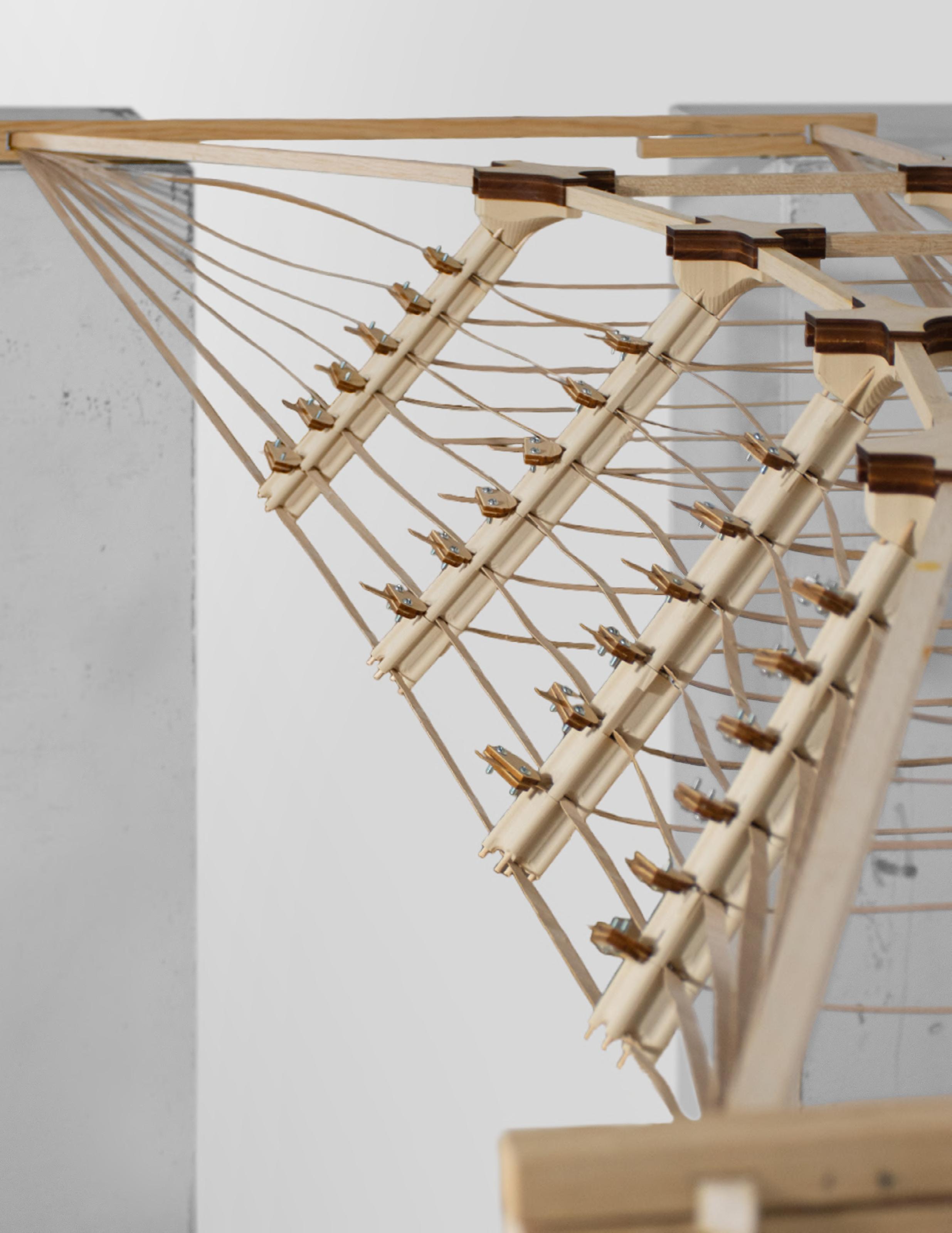
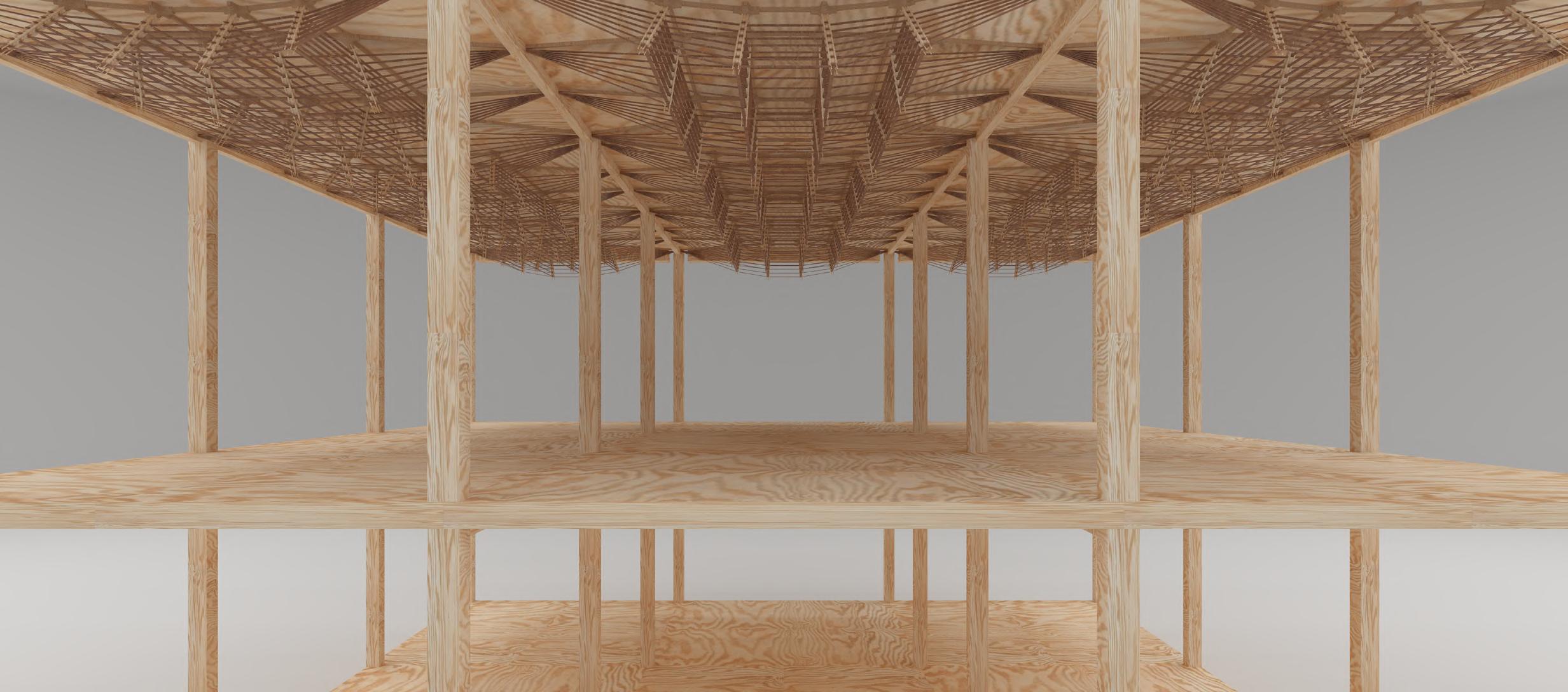
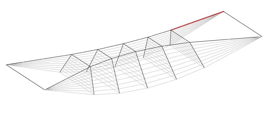
In order to generate a high structural efficiency system, our first step is to design a funicular structural form, in which the only type of forces in the structural members are tension and compression, from that we can reduce the cross section of our structural members significantly. The method of 3D graphic statics help us visualize the force of funicular system, so we can manipulate it to design the structure.
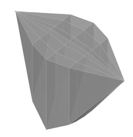
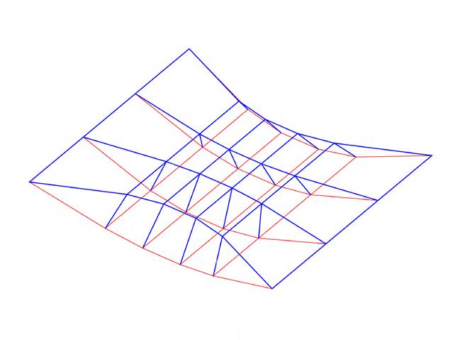
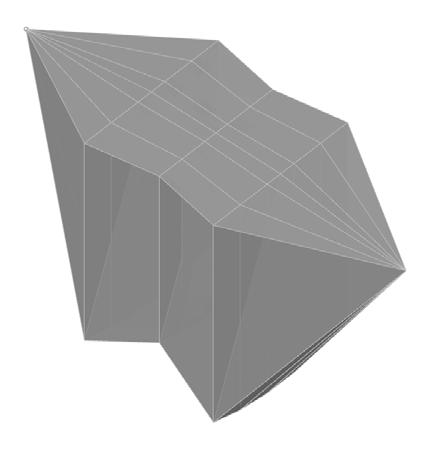
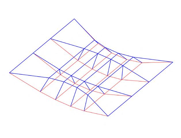
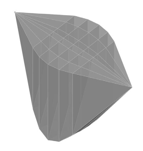
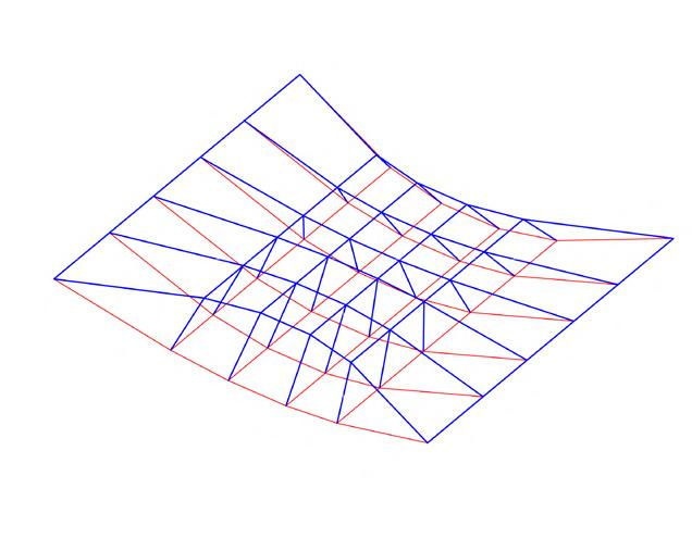
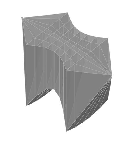
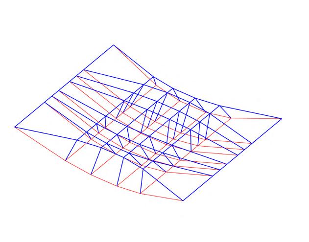
The 3D graphic static design process of the form can be seperated in to two aspects, the planar profile and the sectional profile. The force distribution was desinged and converted into a self-intersecting force diagram, in order to generate tension-compression combined structure system.
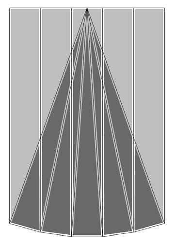
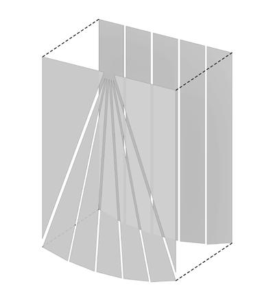
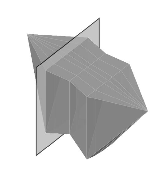
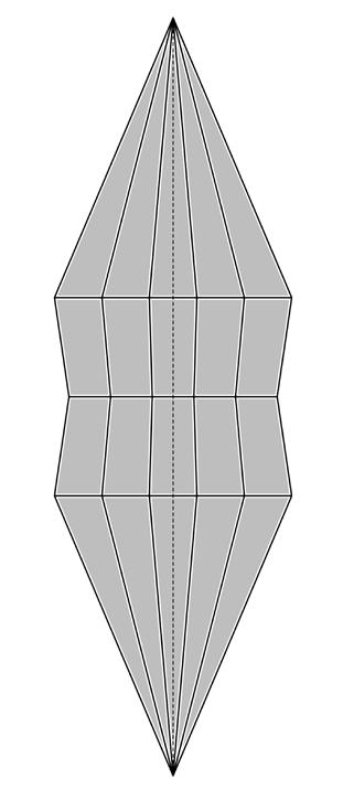
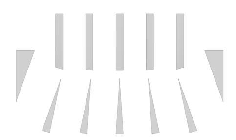
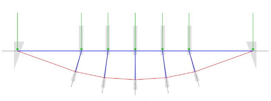
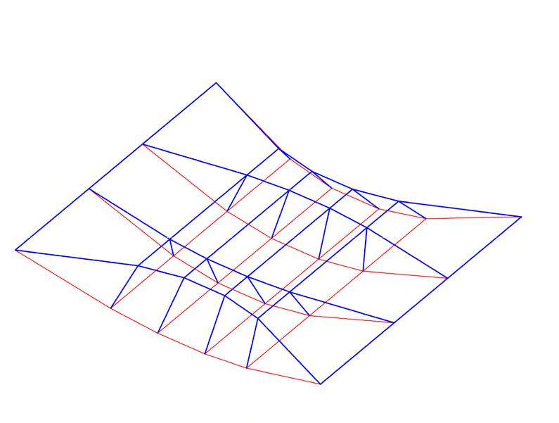
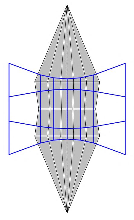
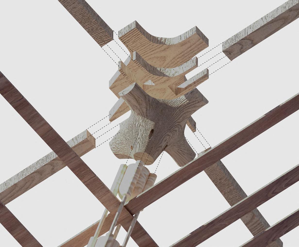
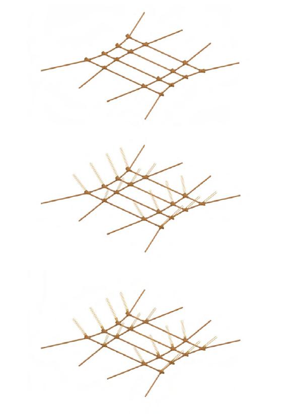
assembled members
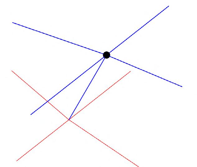
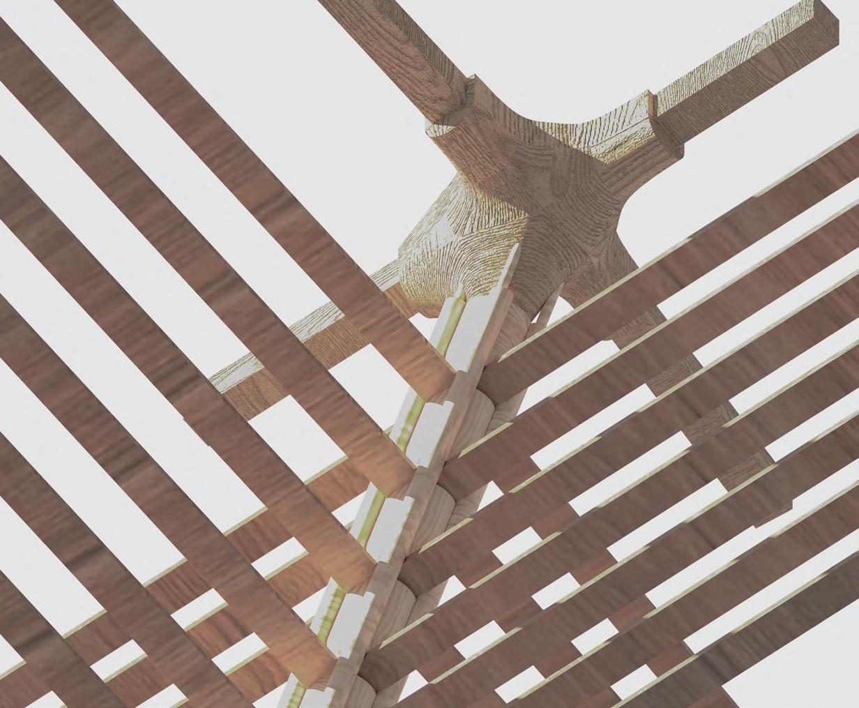
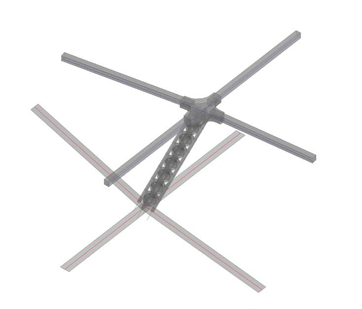
- Single Node
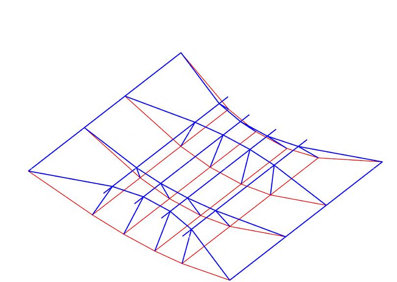
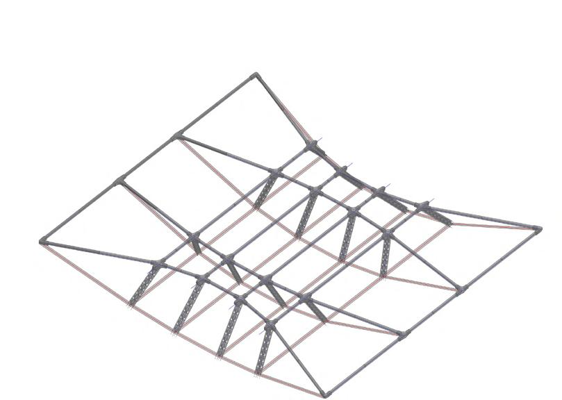
exploded members Input - Whole System
- Whole System Input - Single Node
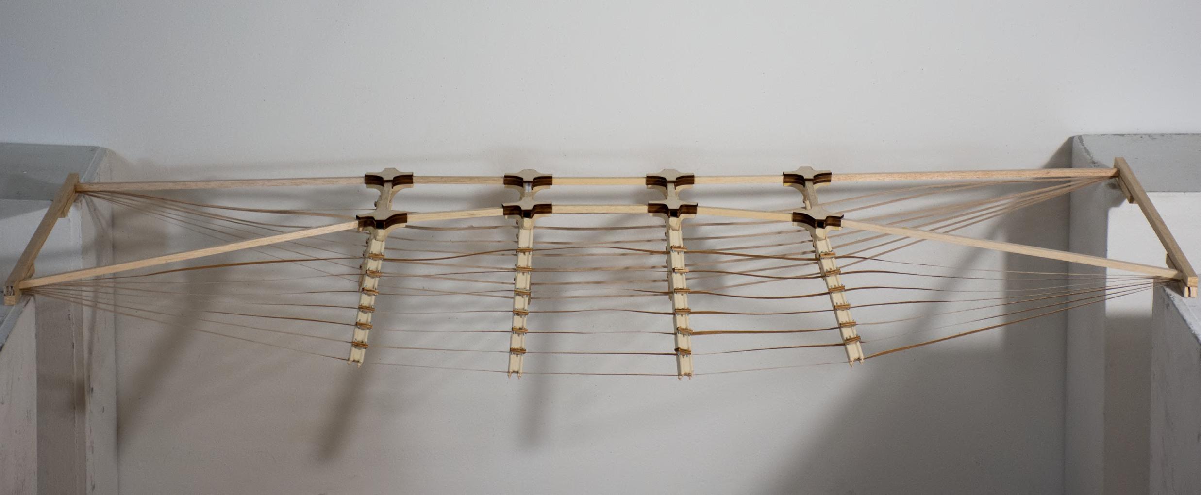
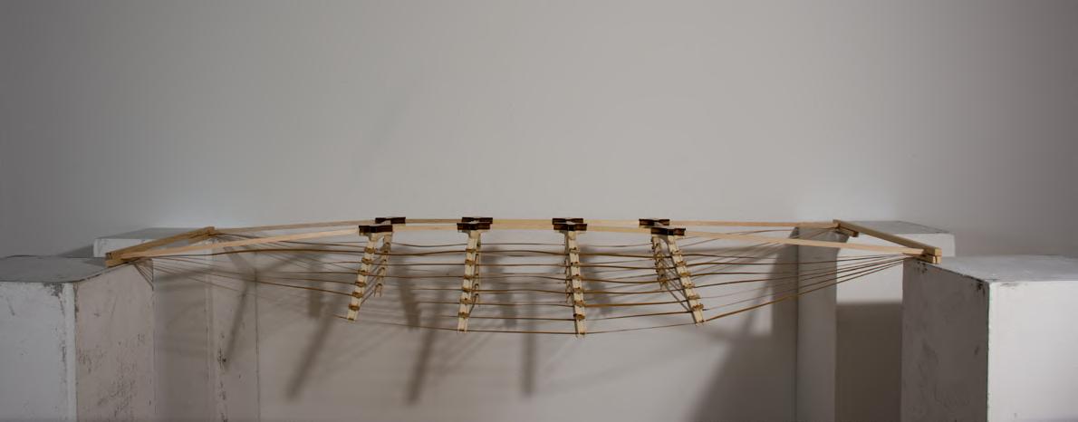
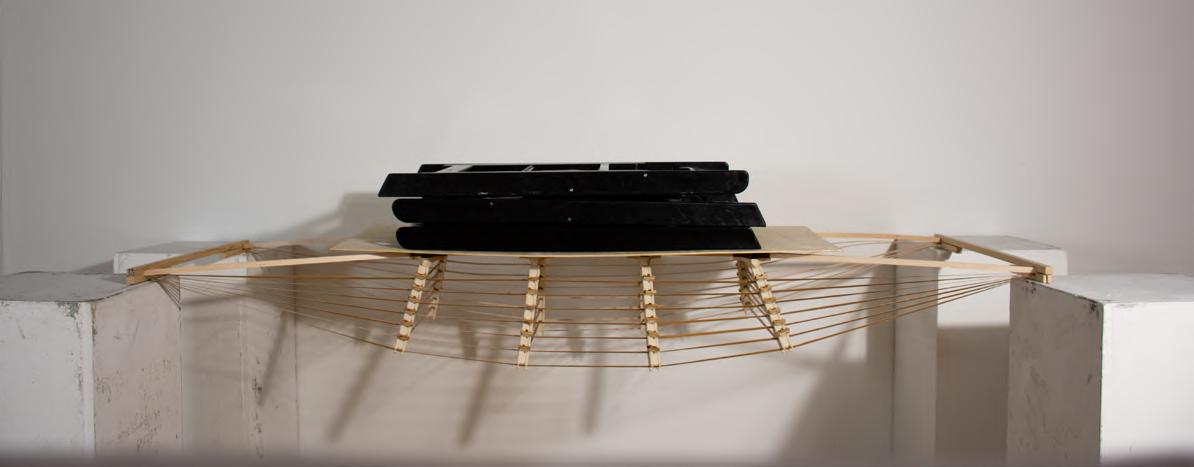
photograph before load test
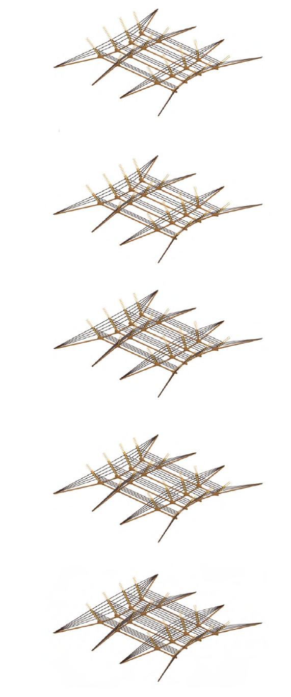
Phase 1
Construct Compression Members
Phase 2 Weave Tension Members
Phase 3 Flip and Fix the Structure
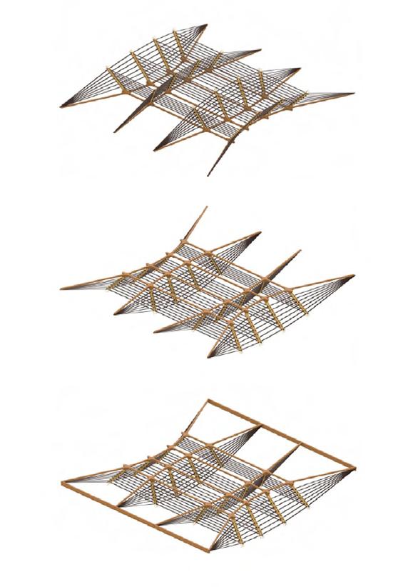
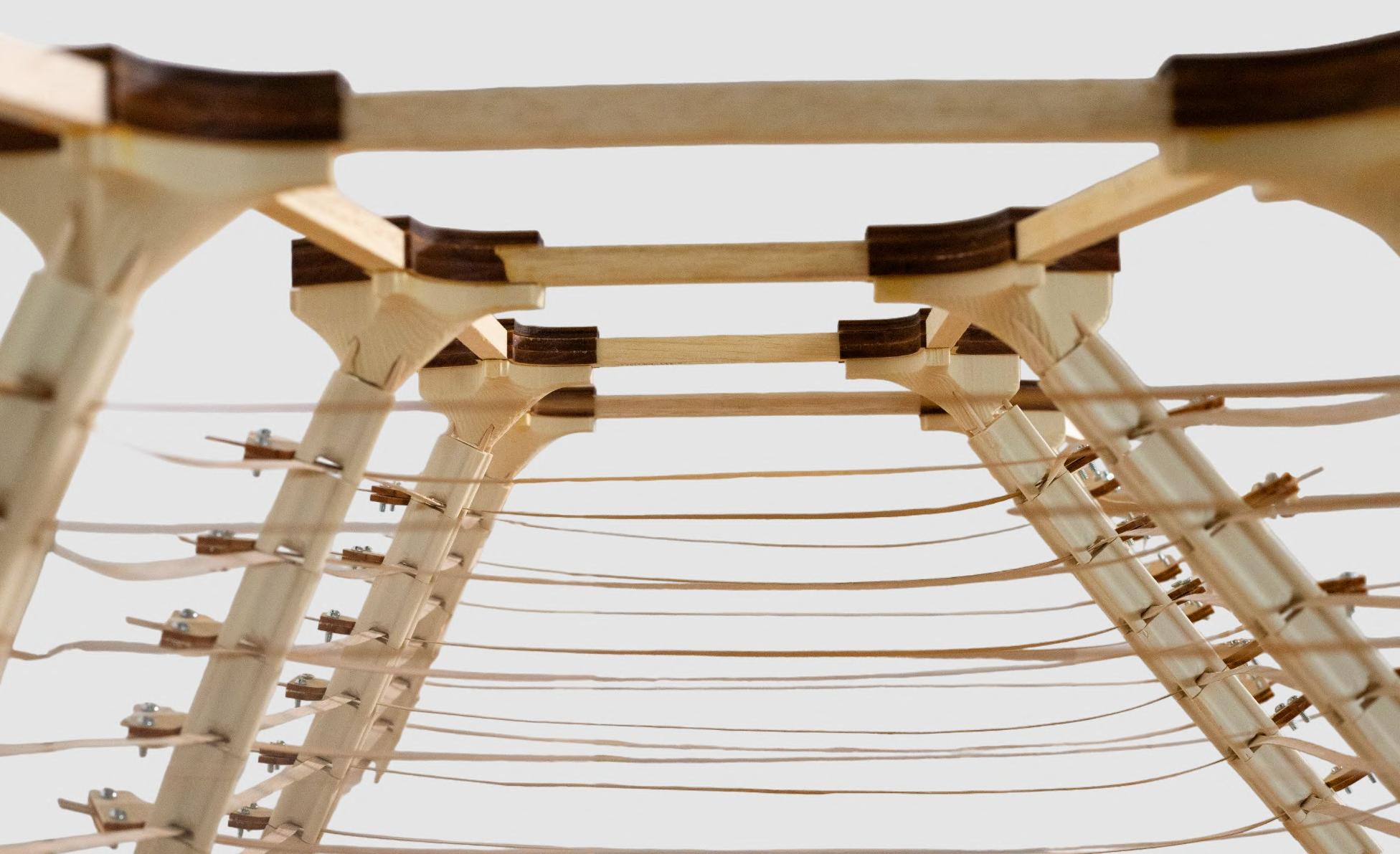
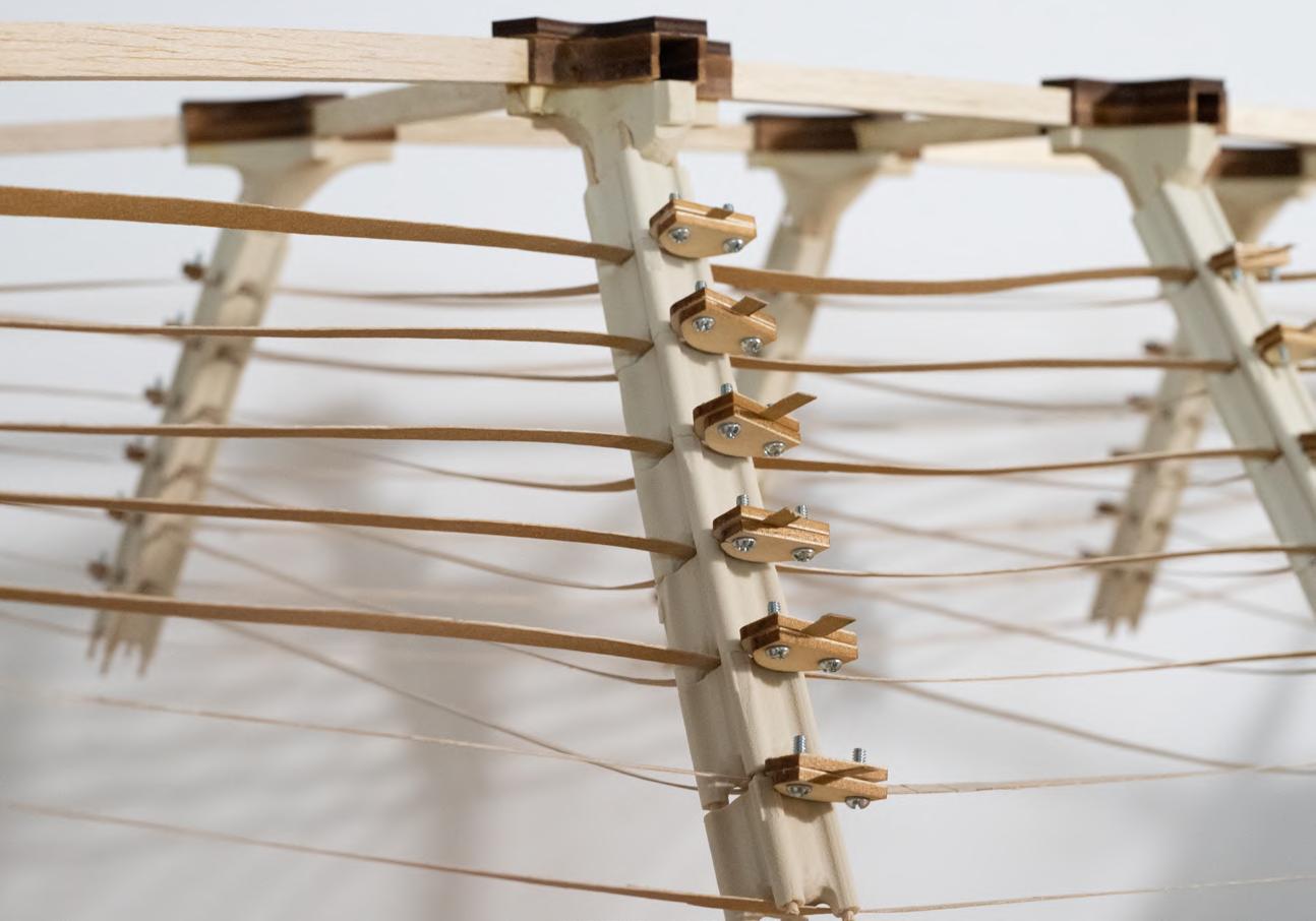
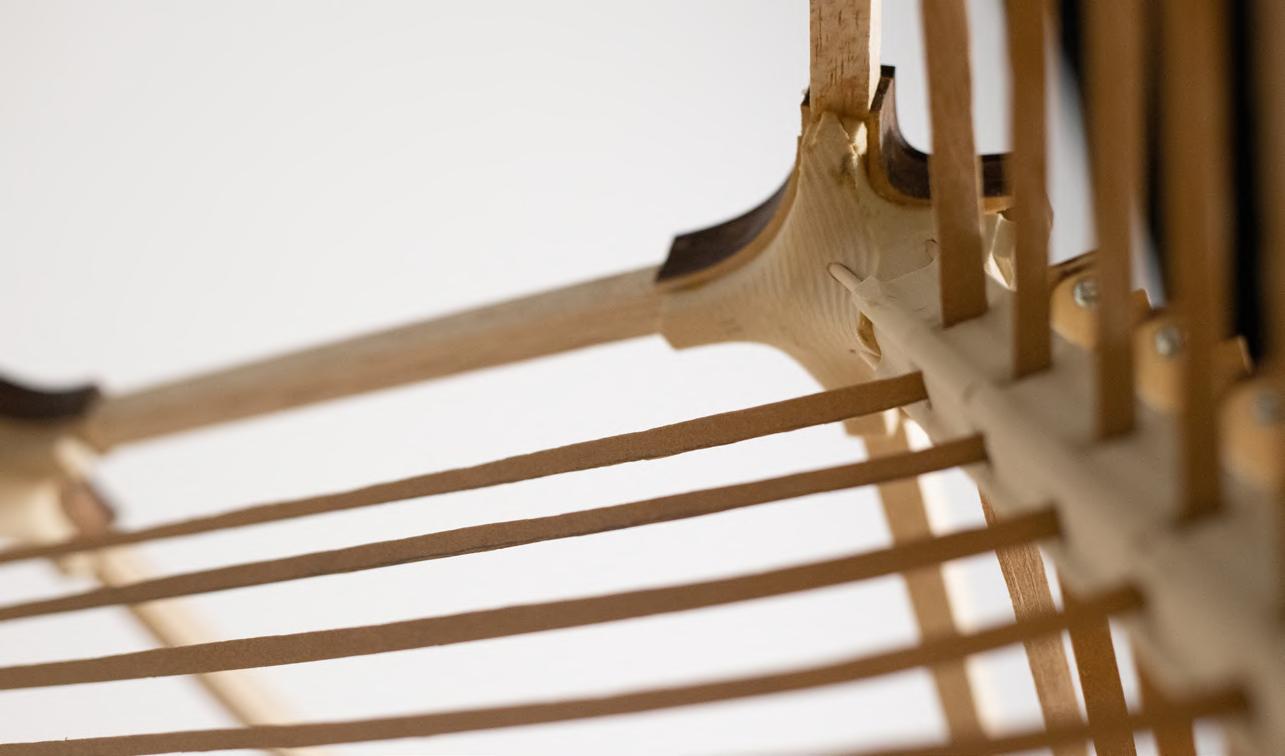
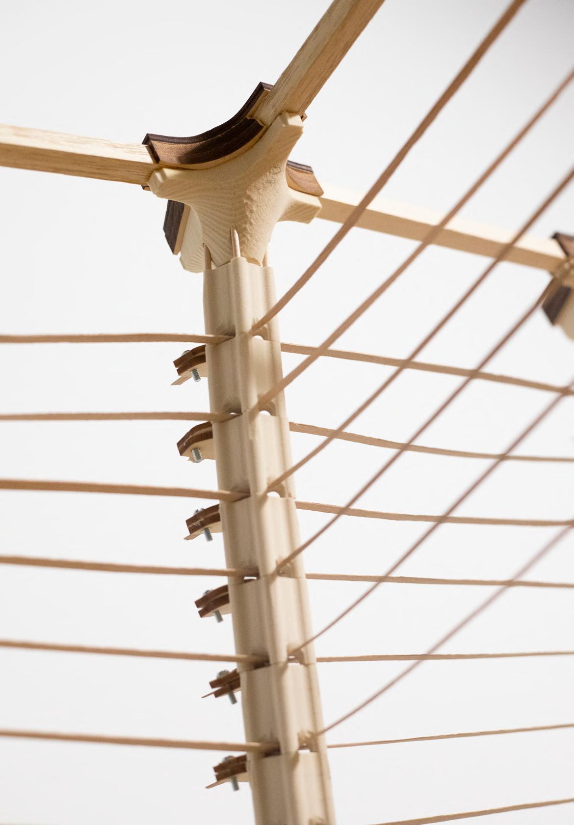
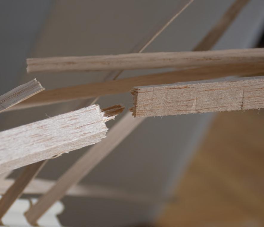
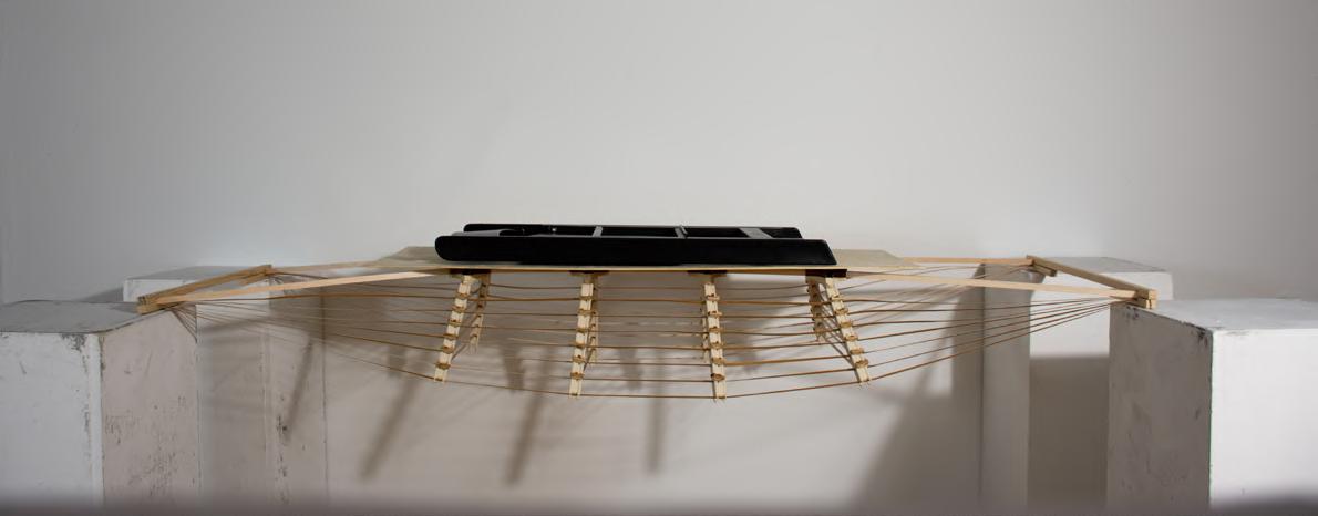
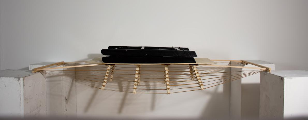
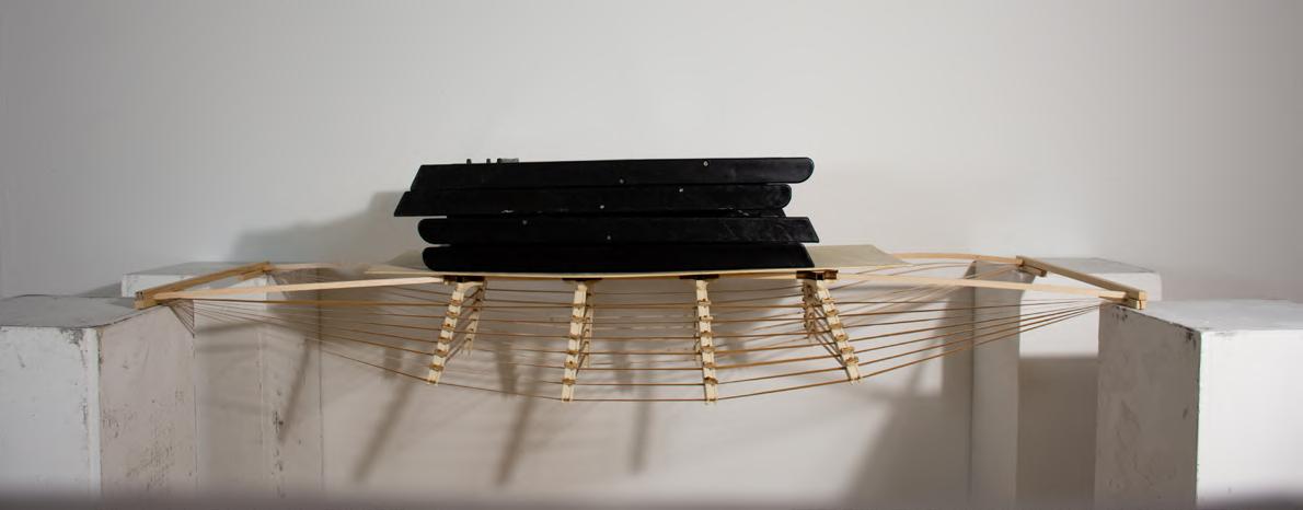
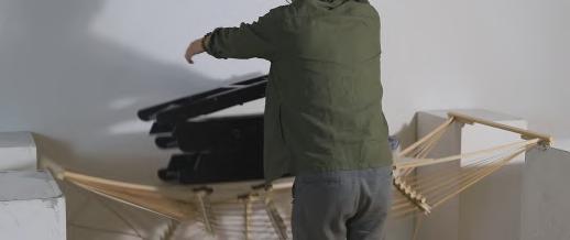
The self-weight of this structure is 1.8lb, and the maximum load it took before failure is 32lb (4 chairs)This set of photos shows the process of the physical load test. An interesting observation during the process is : the additional tension members were not performing when there is no load on the structure, and they get more loose when they are closer to the compression members on the very top of the structure. However, when we are gradually adding weights to the system, they get more tight following the sequence from bottom to top. From this, we can speculate the tensile forces on each members: as assumed, the tension goes mainly on the bottom chords of the structure, which are the only members that are generated by the form finding method, however, the additional members starts to share laods from the bottom chords when the external forces are increasing.
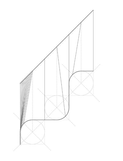
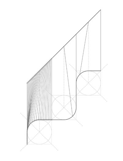
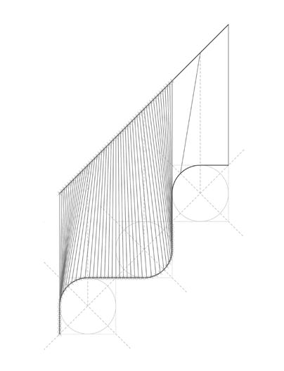
Arch
Location: Governor's Island, New York
Instructor: Marion Weiss
Team Member: Chen Su, Boyu Xiao
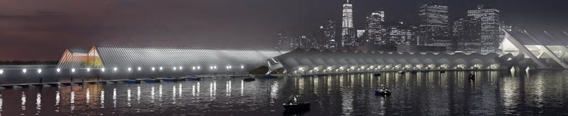
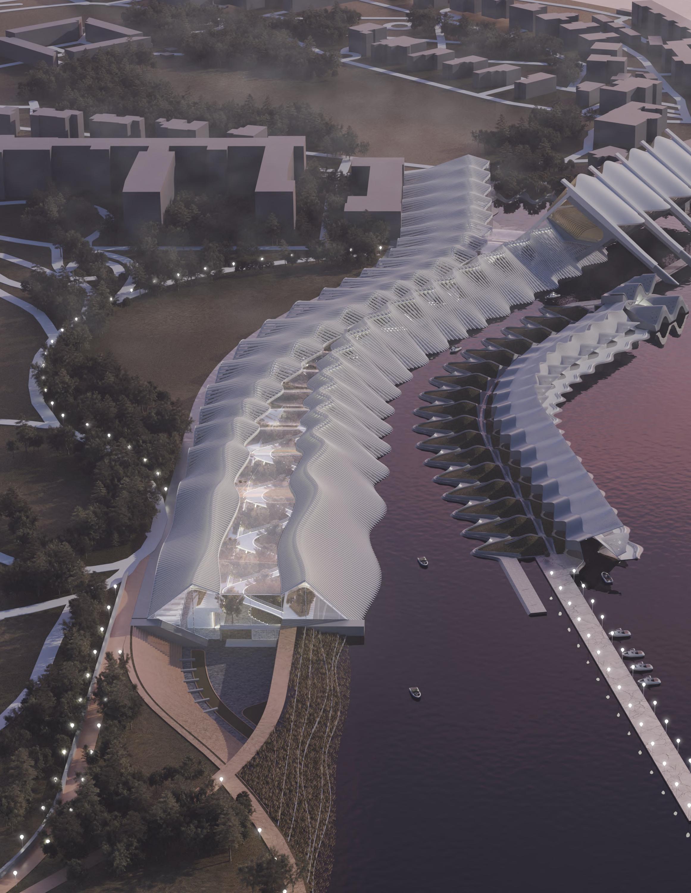
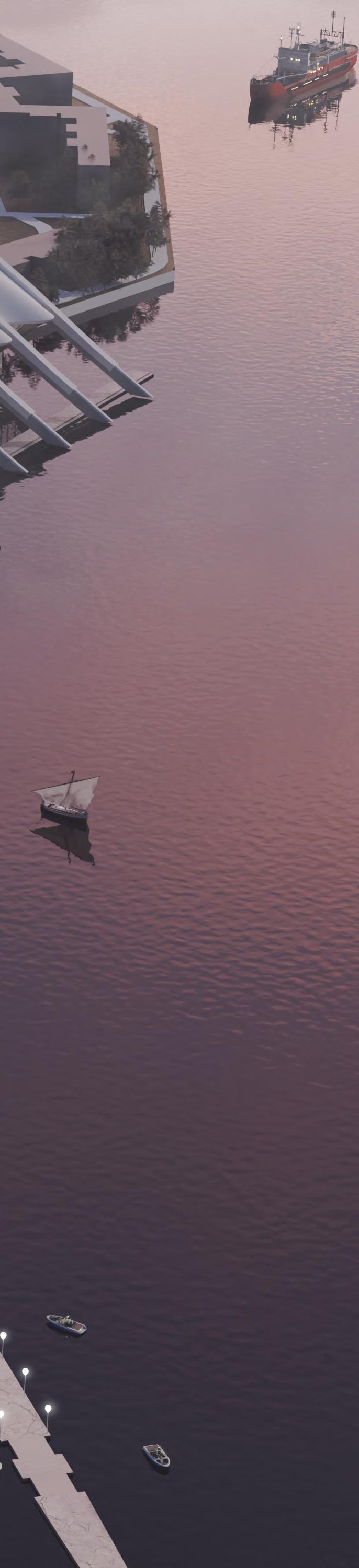
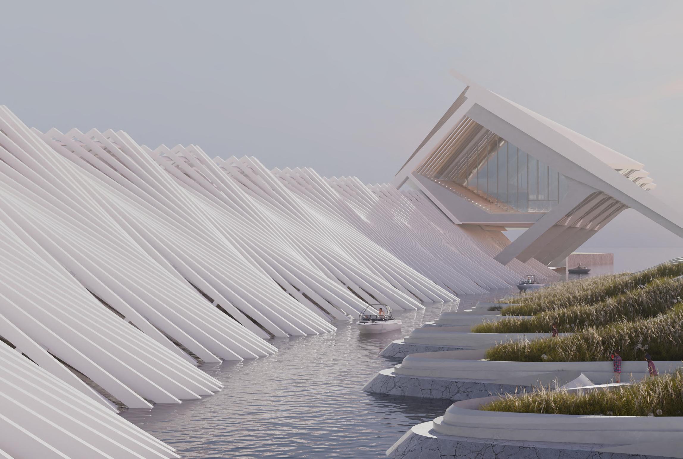
Governors Island, once a military base, was acquired by New York City with the vision of transforming it into a vibrant public space. Initially, an ambitious effort was to attract academic institutions, but the lack of essential infrastructure deterred universities from establishing a presence. Now, we propose building a comprehensive conservatory on the island, creating a compelling opportunity to attract esteemed institutions.
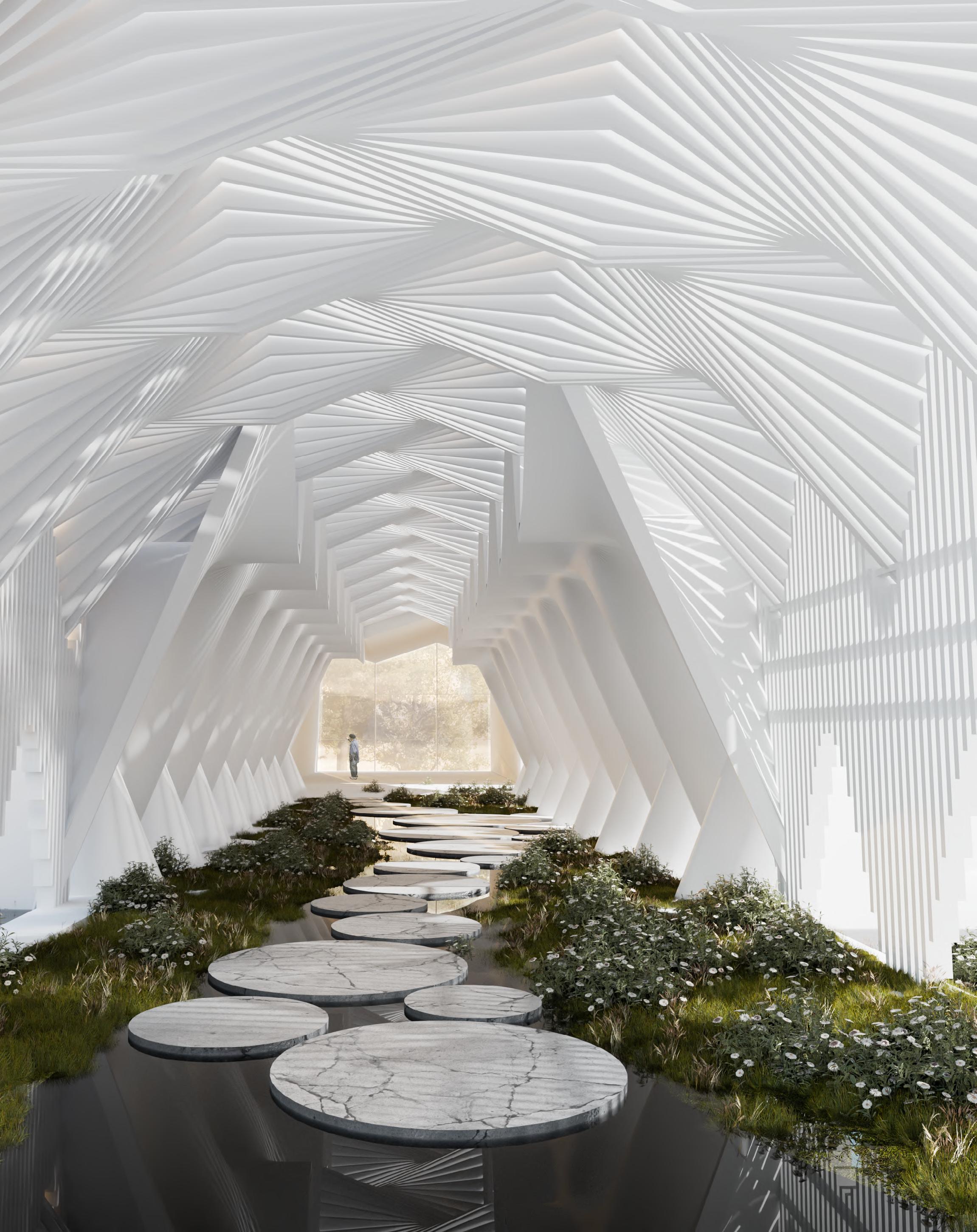
Our initiative includes the development of a botanical conservatory, an aquatic conservatory, and a state-of-theart aquarium. This trio of facilities is intended to create an integrated ecosystem that supports academic research and educational activities. The project is not only envisioned as a hub for educational collaboration but also as a testing ground for innovative climate resilience strategies.
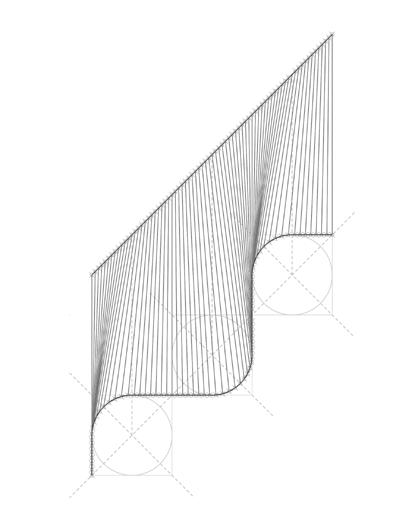
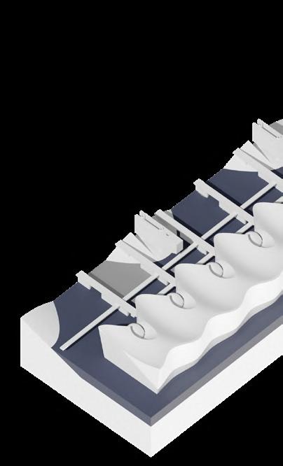
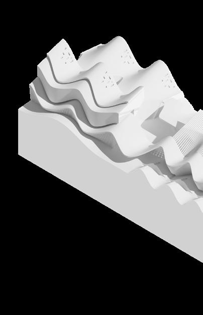
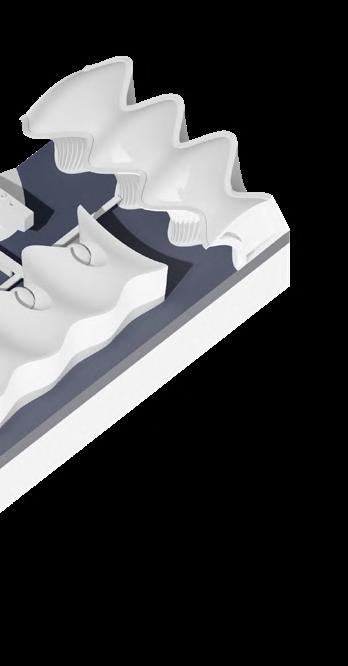
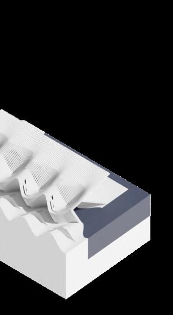
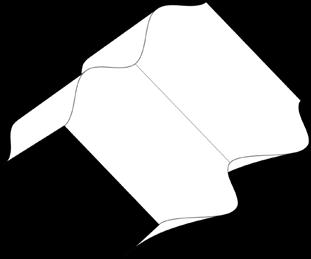
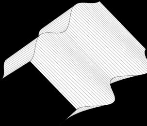
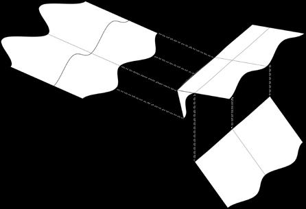
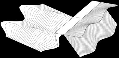
During the concept generation phase of the project, we made different prototypes to guide the final design language of the project, and in order to better integrate with the theme of water, we ended up adopting a corrugated geometric generation logic.
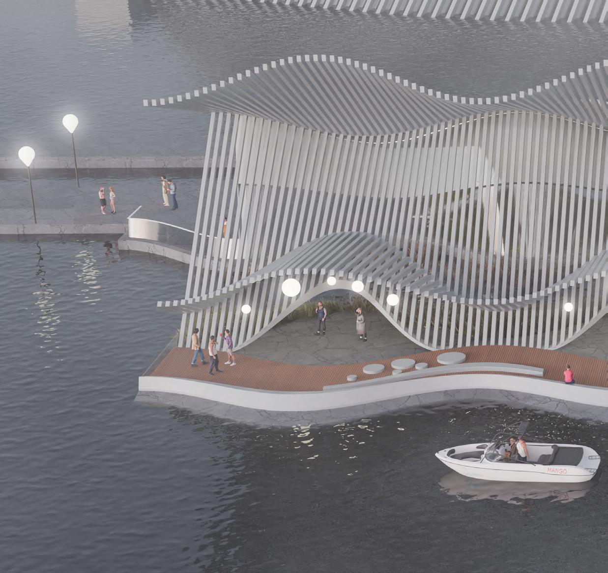
The coastal area faces a significant lack of interactive public spaces connecting with the water. Our project addresses this by strategically delineating the area to establish two primary zones.
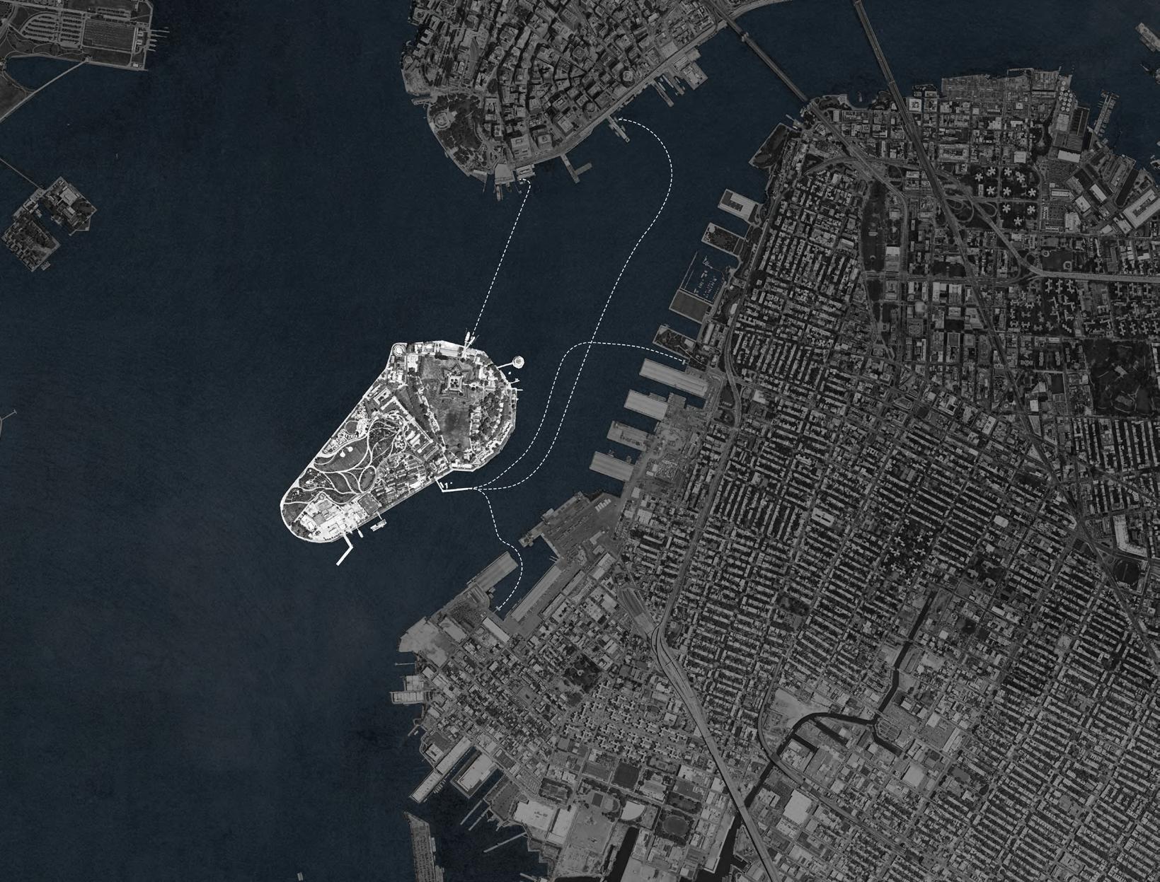
In order to incorporate island so that water transportation
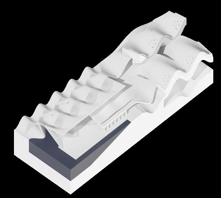
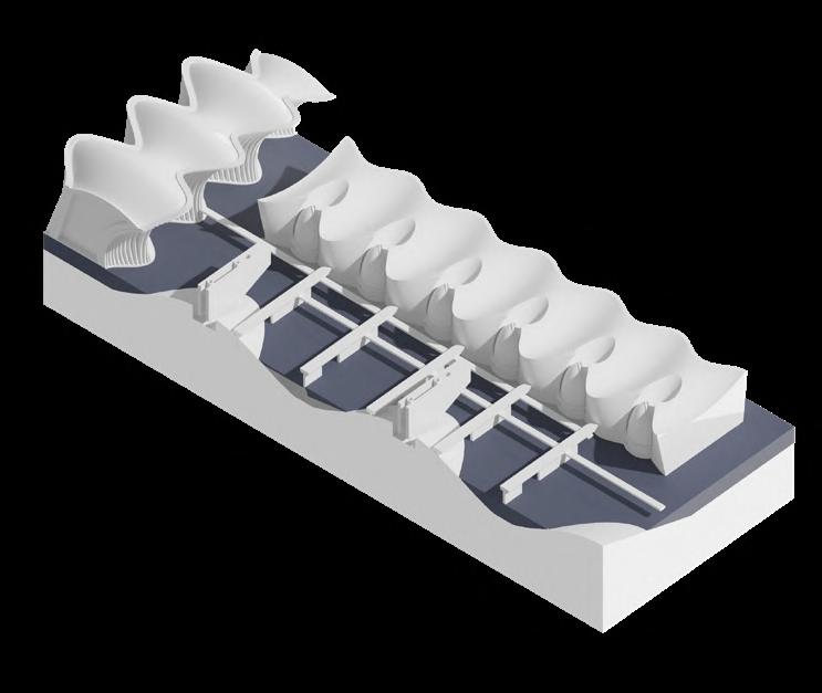
incorporate the existing water transportation routes into the design, we recreated the waterfront of the transportation could become part of the botanical garden.
curve introduce new curve create new landing, the 'zipper'
Form
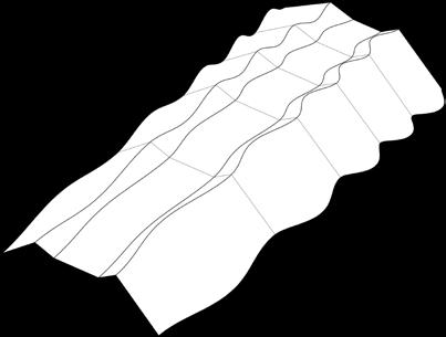
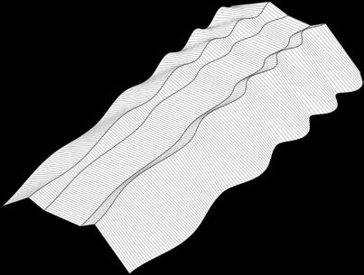
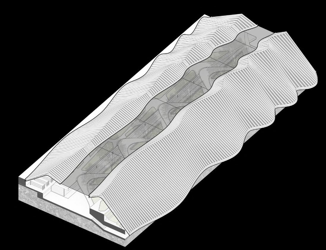
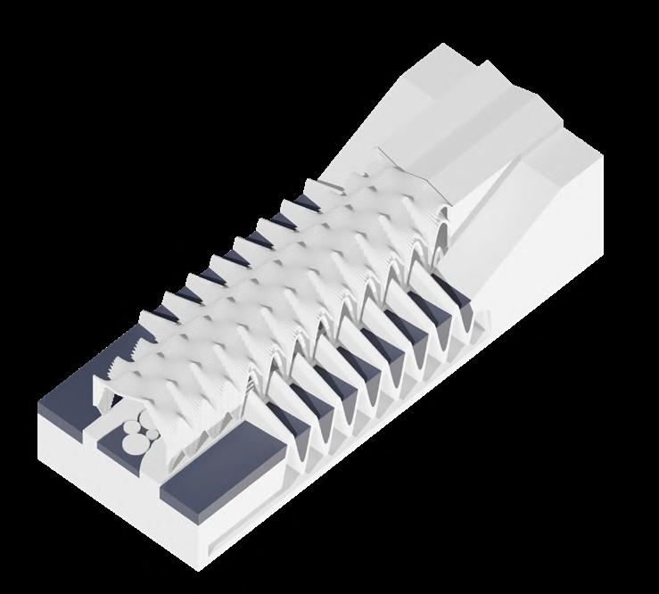
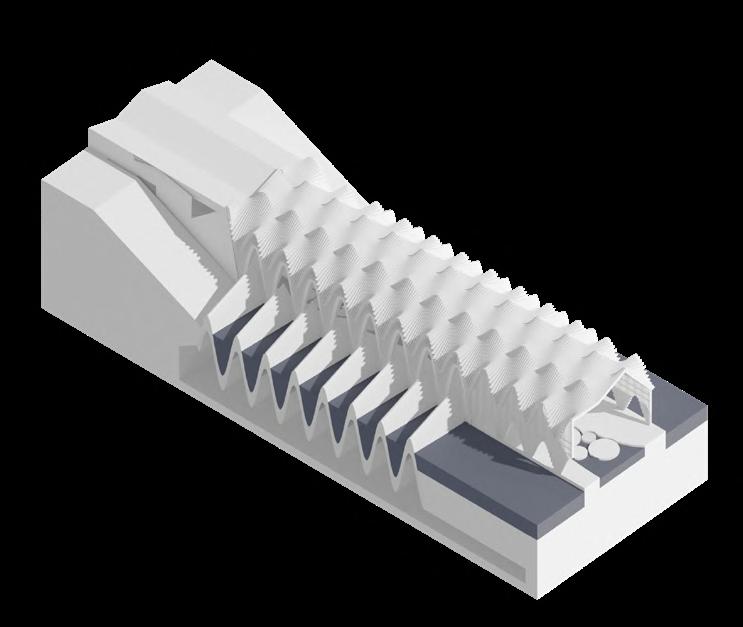
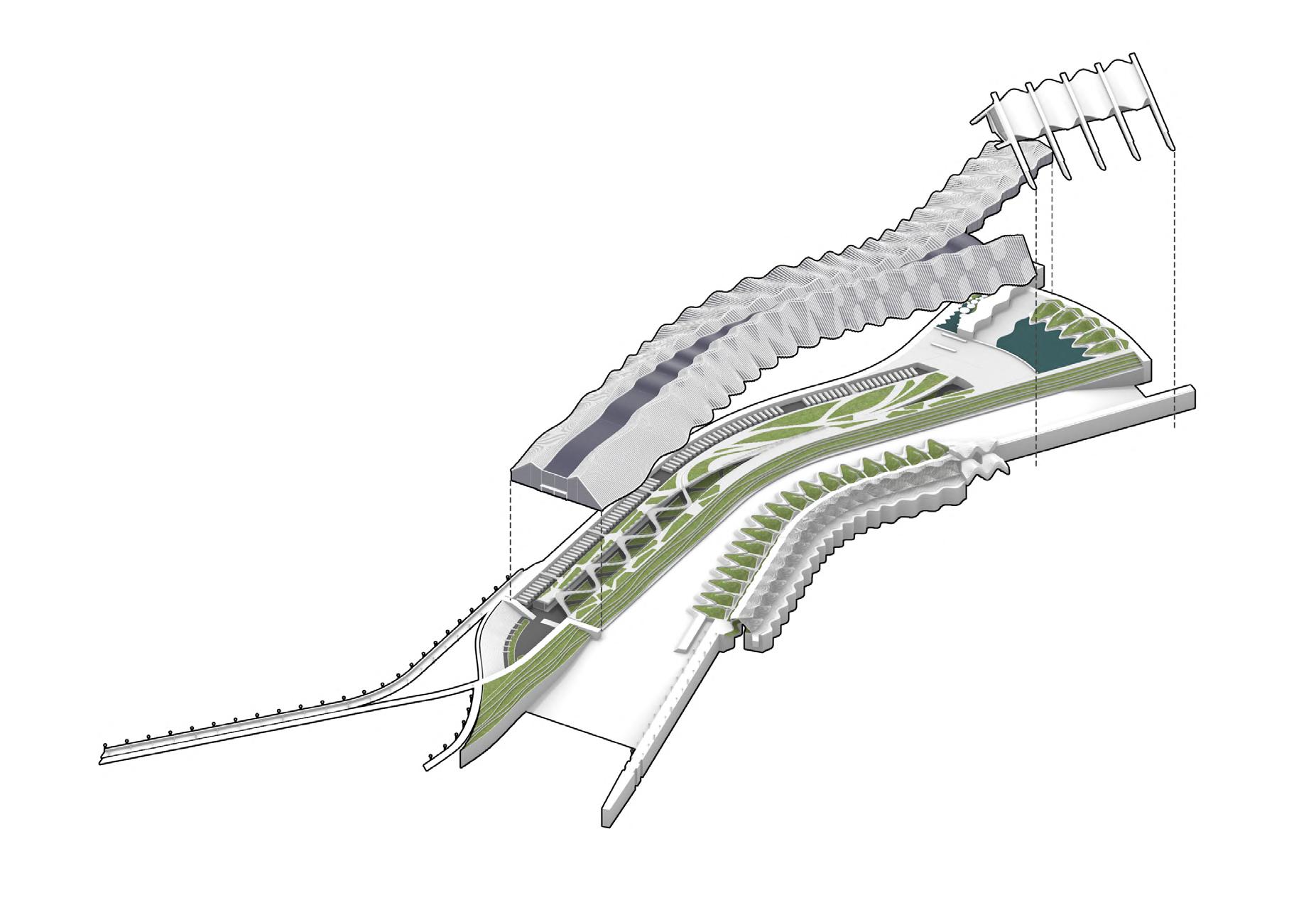
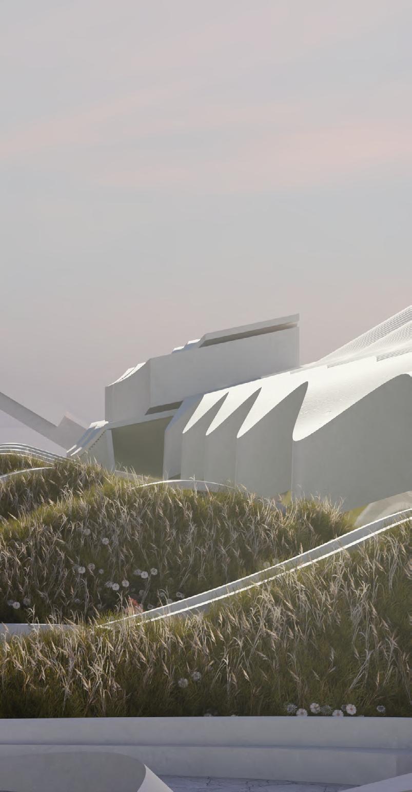
The conservatory part has a linear design, subdivided into three climate zones
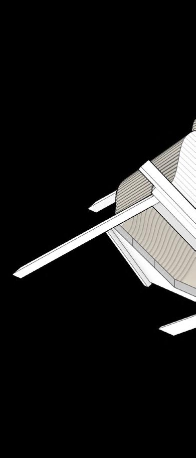
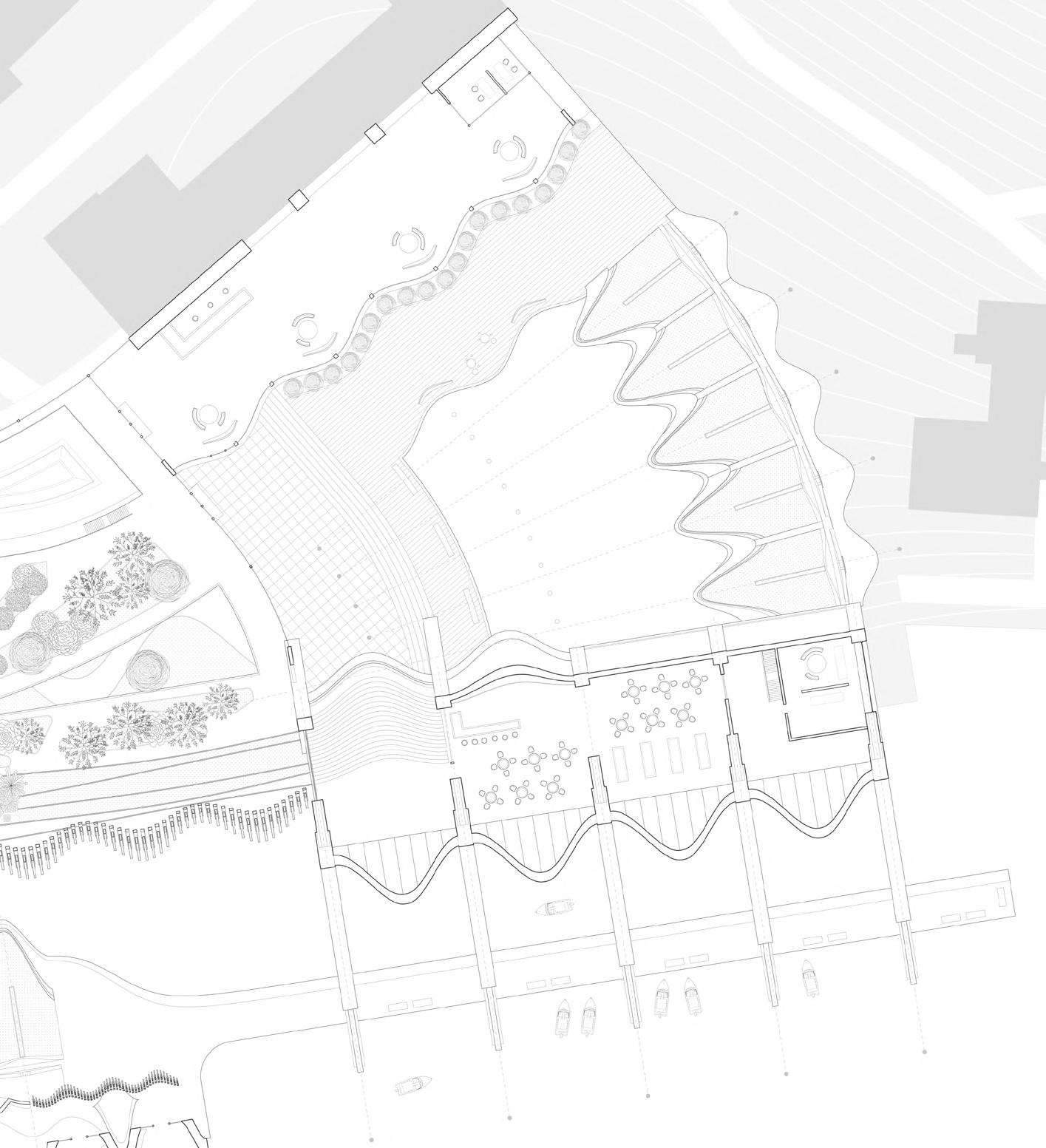
Ground reception for the aquatic garden and the conservatory, building also has an auditorium and a cafe.
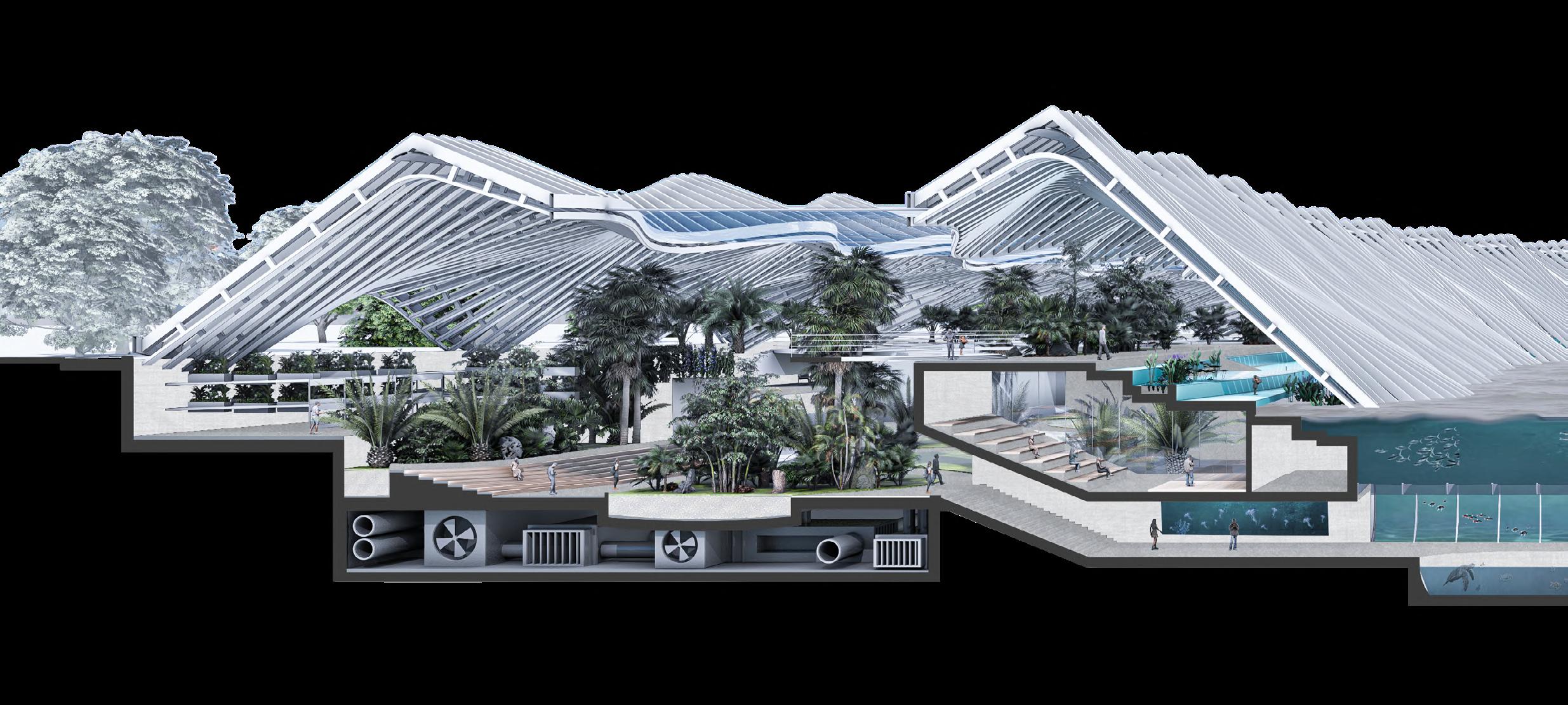
In this project, same geometric generation logic is appllied into three different zones with their own functions. These spaces are designed to foster a comprehensive environment that encapsulates both terrestrial and marine ecosystems.
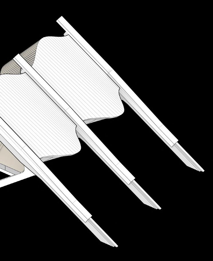
conservatory, this
Detailization
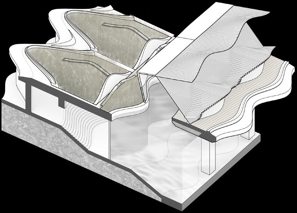
Detailization
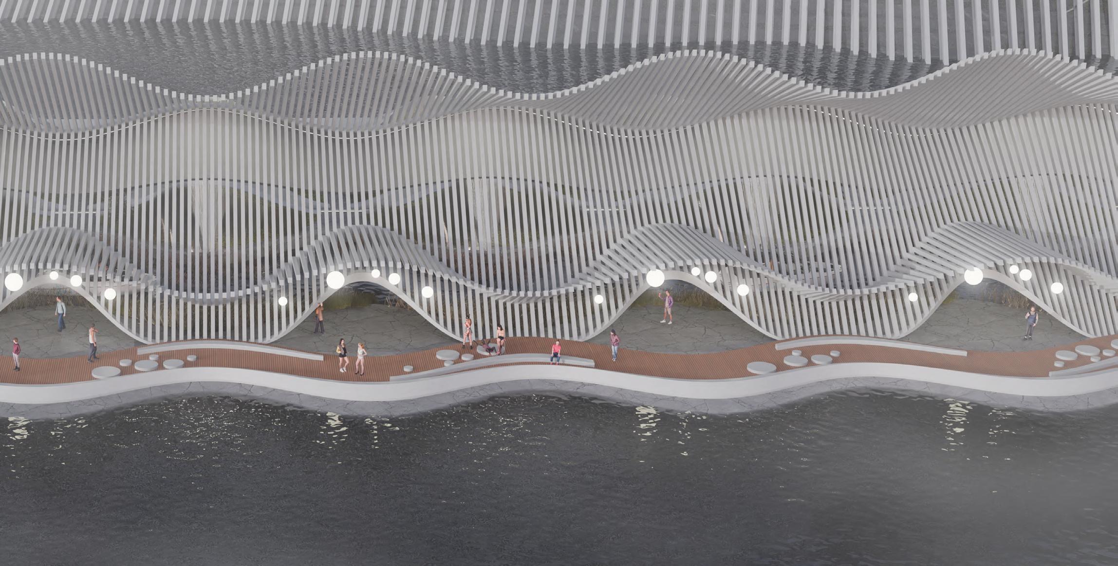
The orginal water edge of governor's island is turned into a water way with marine ecosystems, allowing visits from both ground and waterway
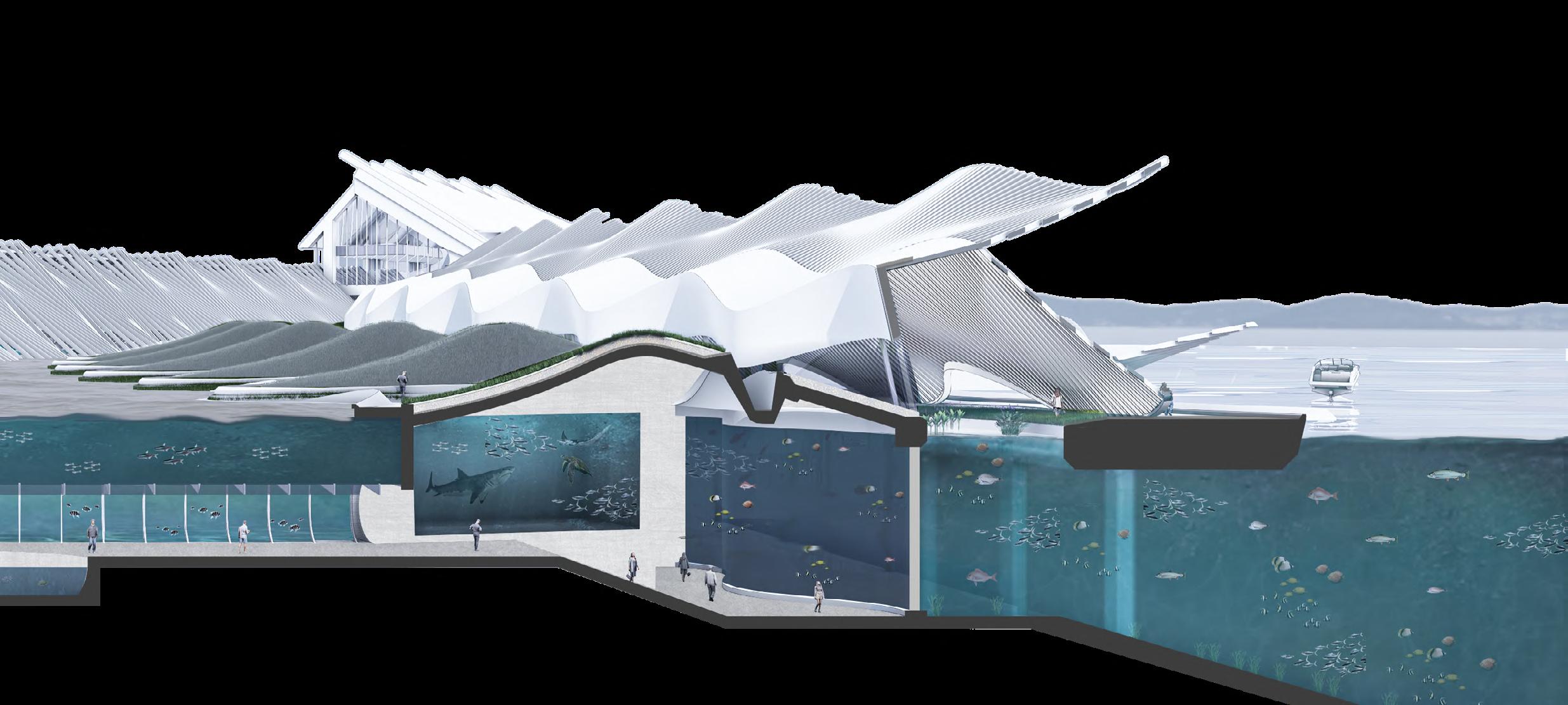
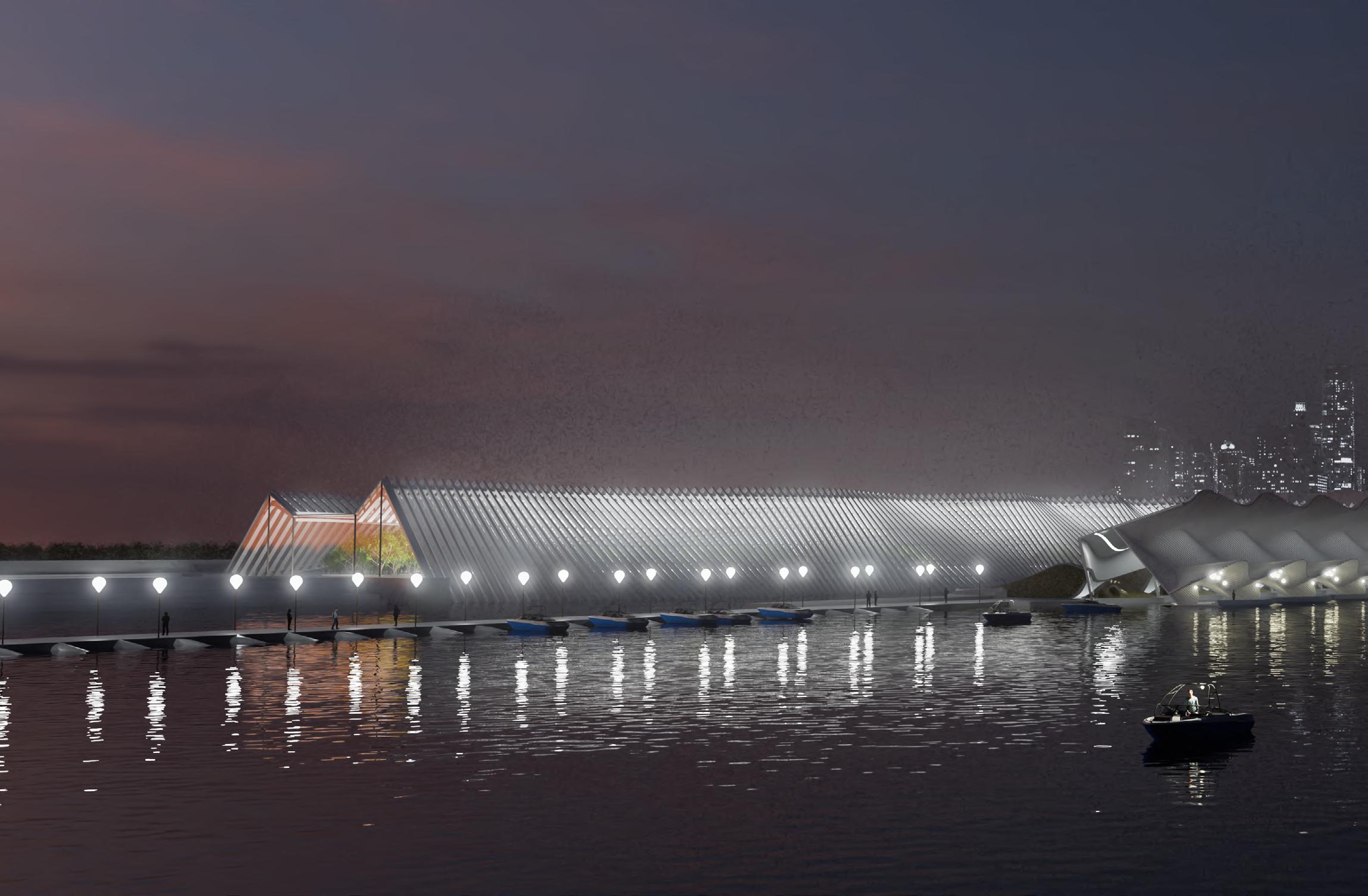
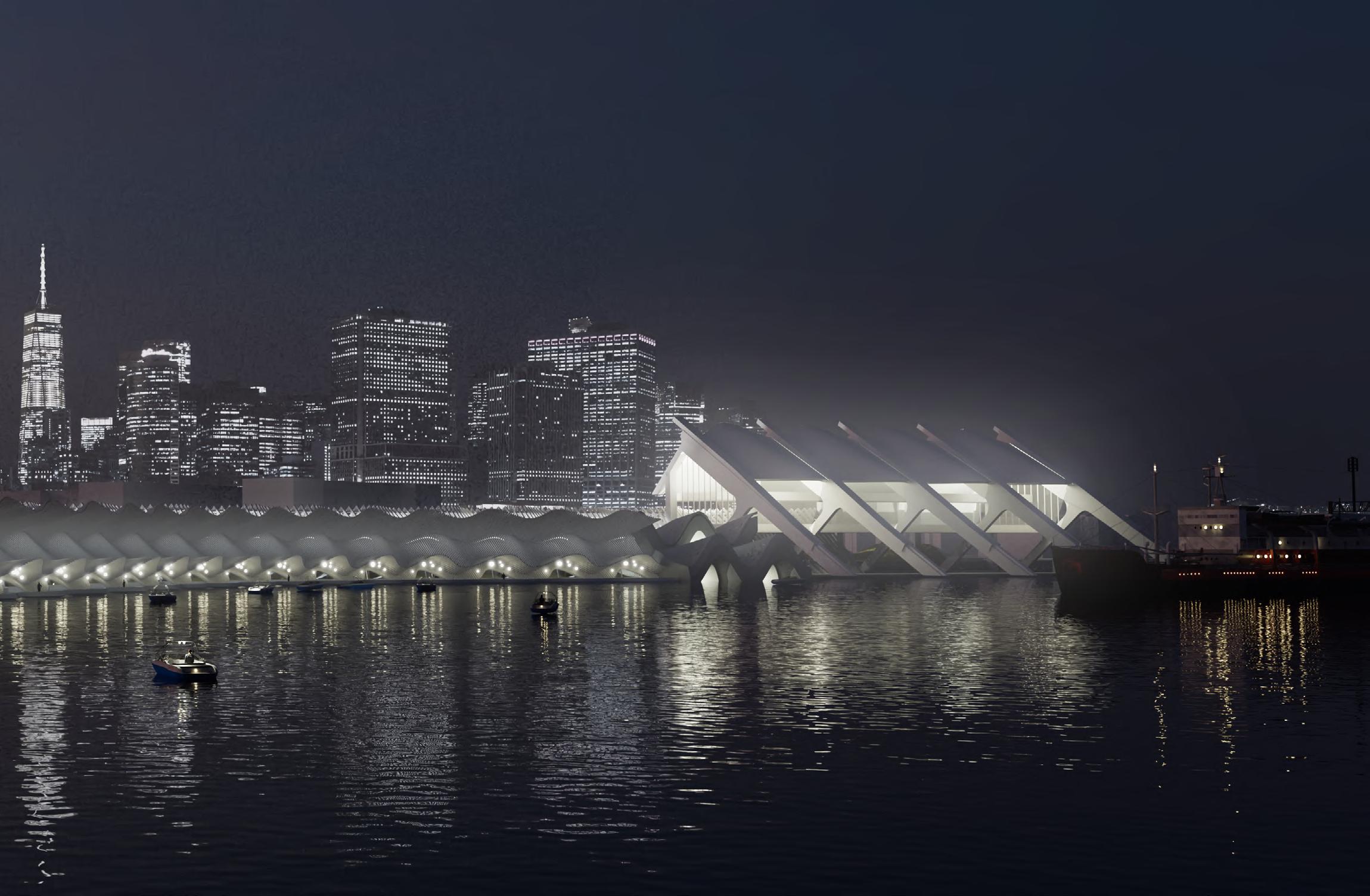
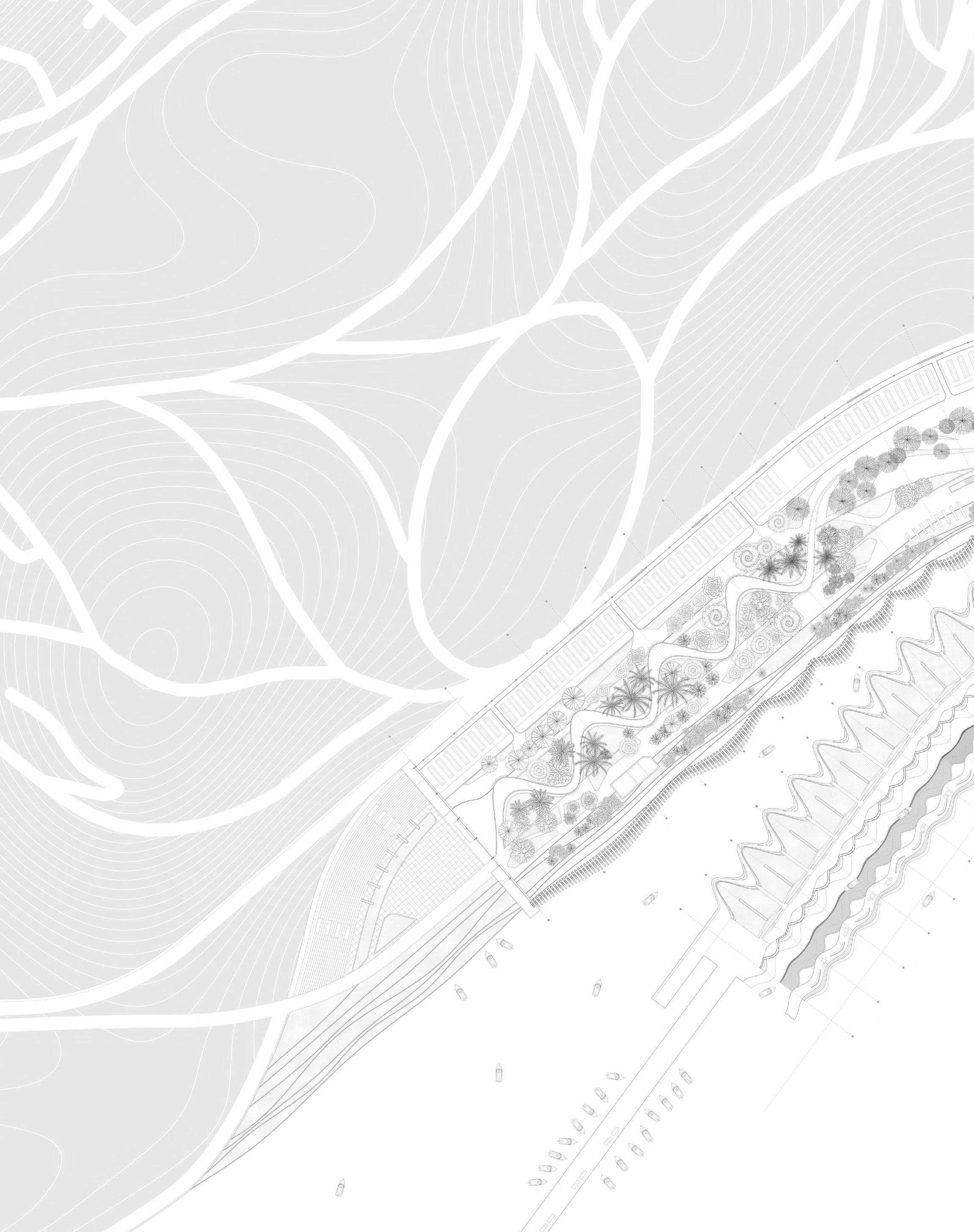
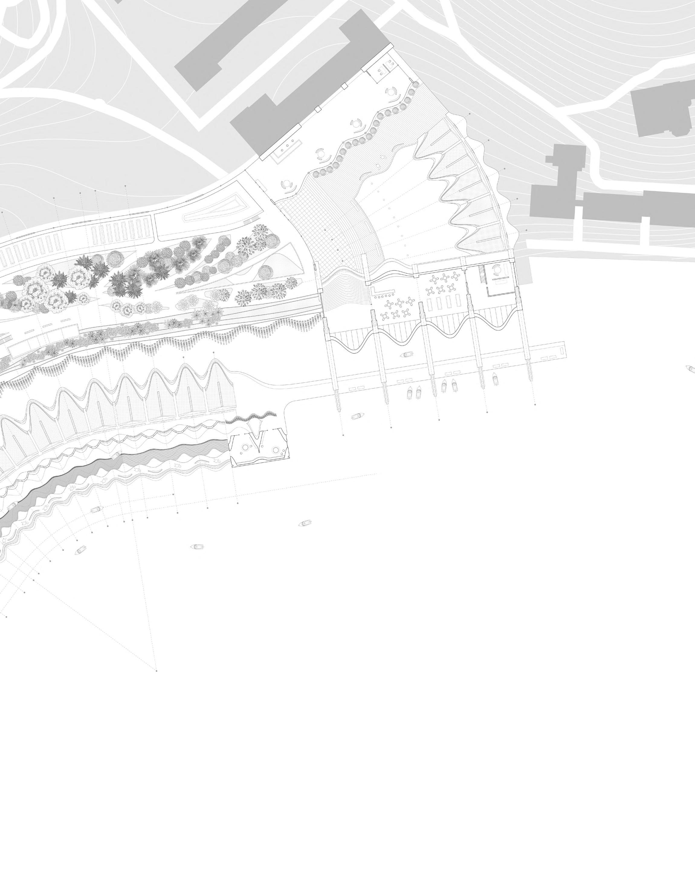
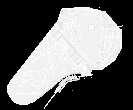
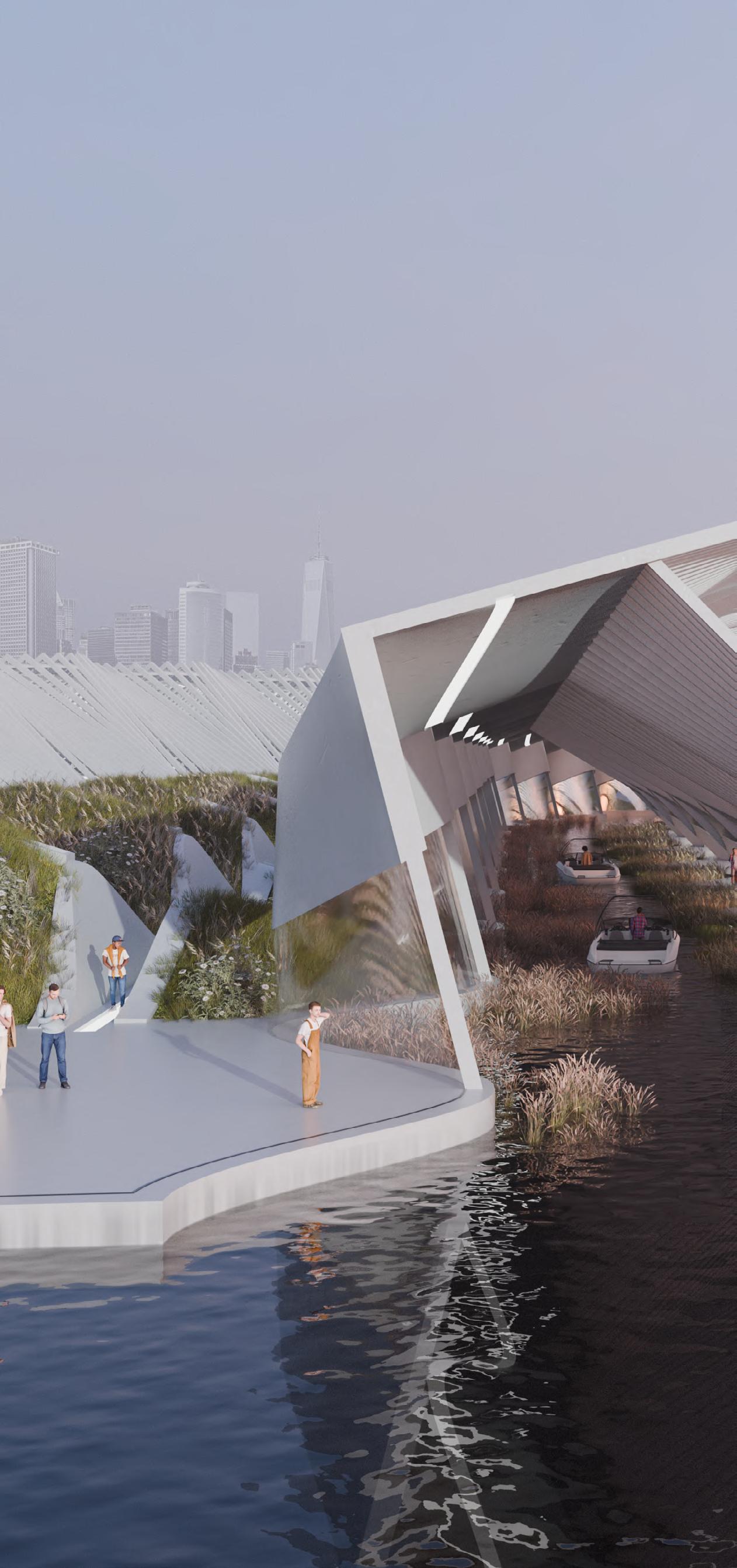
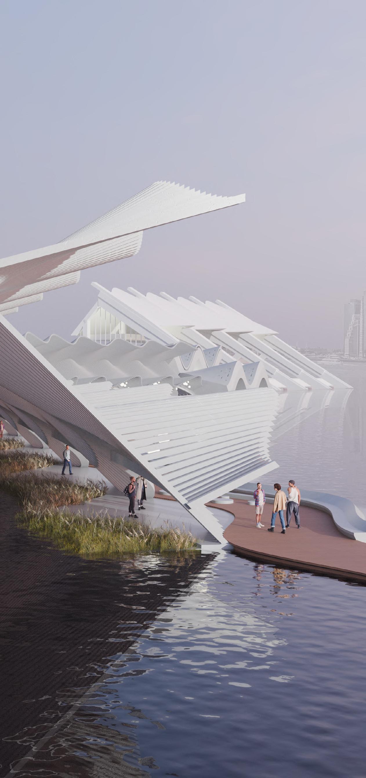
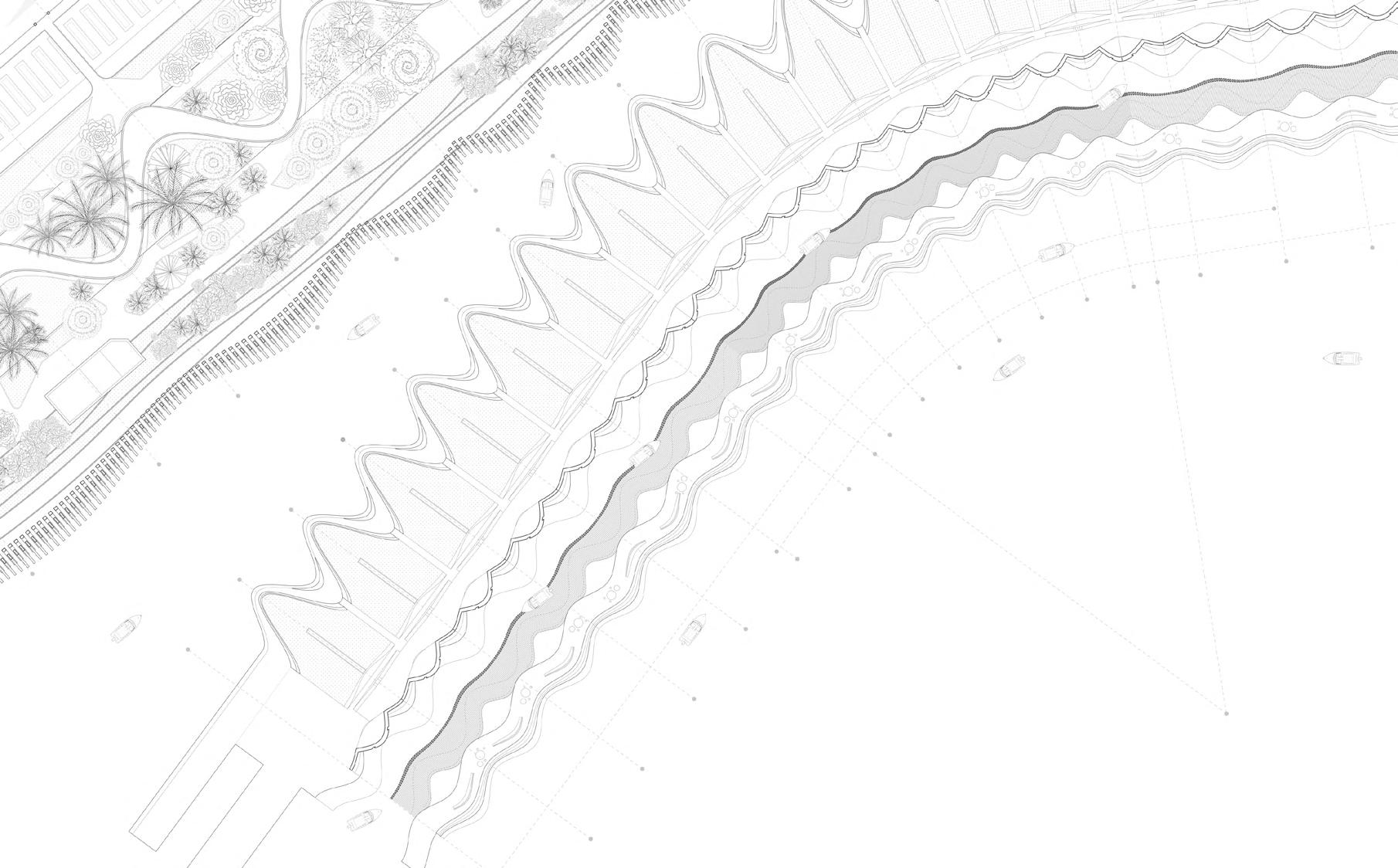
The Botanical Gardens' marine ecosystems are scattered along the aquatic path, which can be accessed directly by cruise ships from New York City, or through the ground entrance on governor's island.
1. Conservatory
2. Underground Pathway
3. Aquatic Pathway
4. Reception / Cafe
5. Ground Entrance

Arch 601: Shifting Hybrids: Adaptive Reuse of the Corbin Building
Location: 13 John St, Manhattan, New York
Instructor: Hina Jamelle
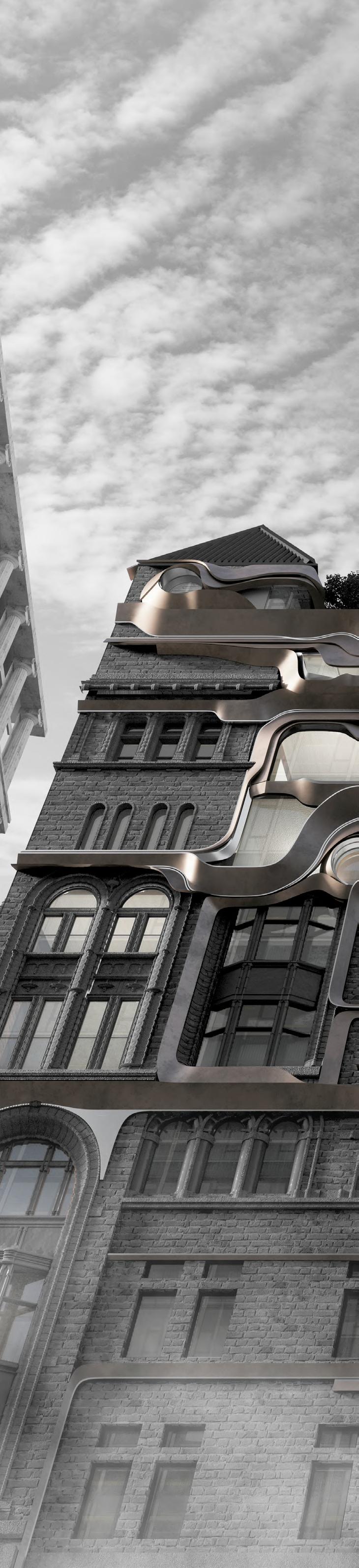
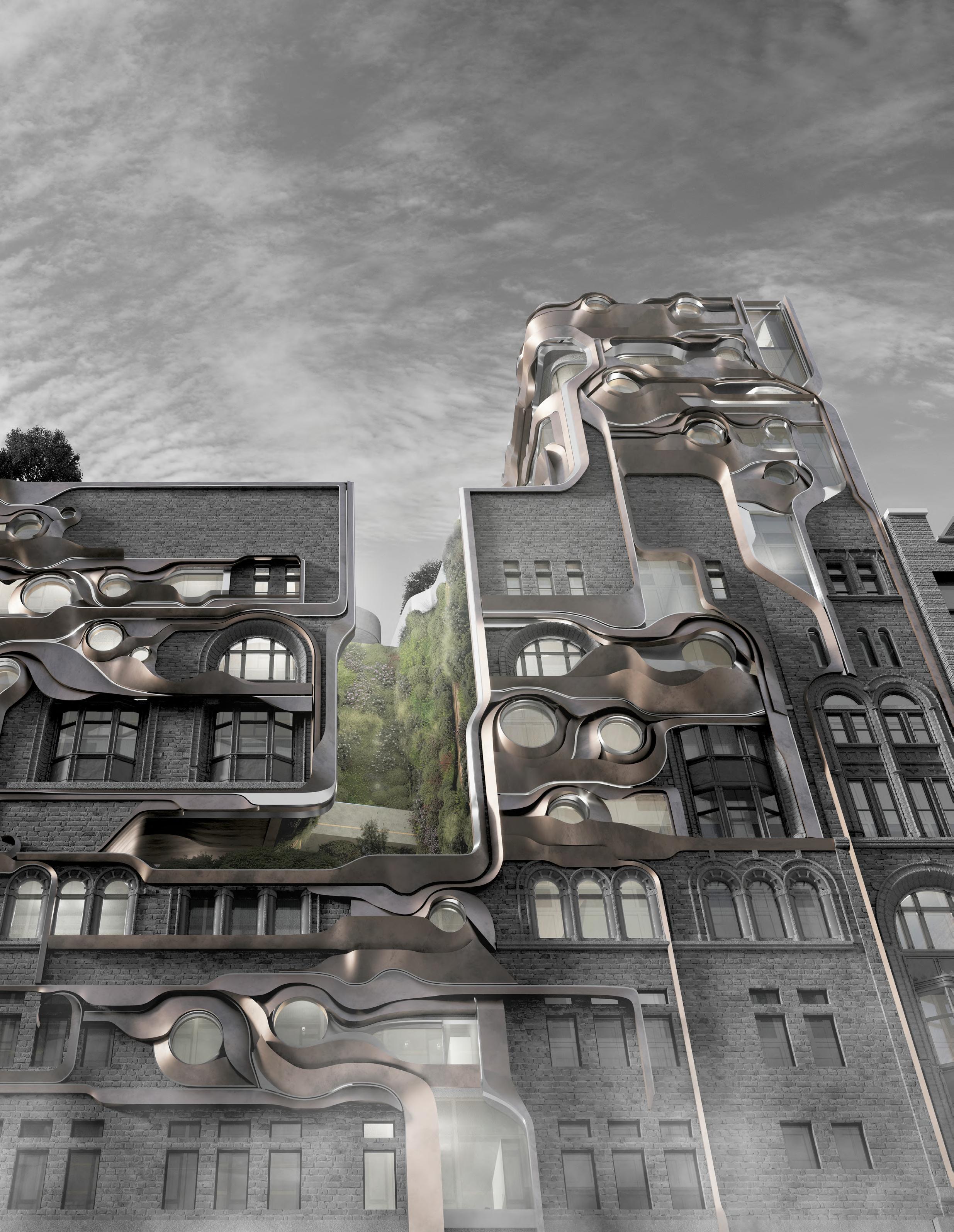
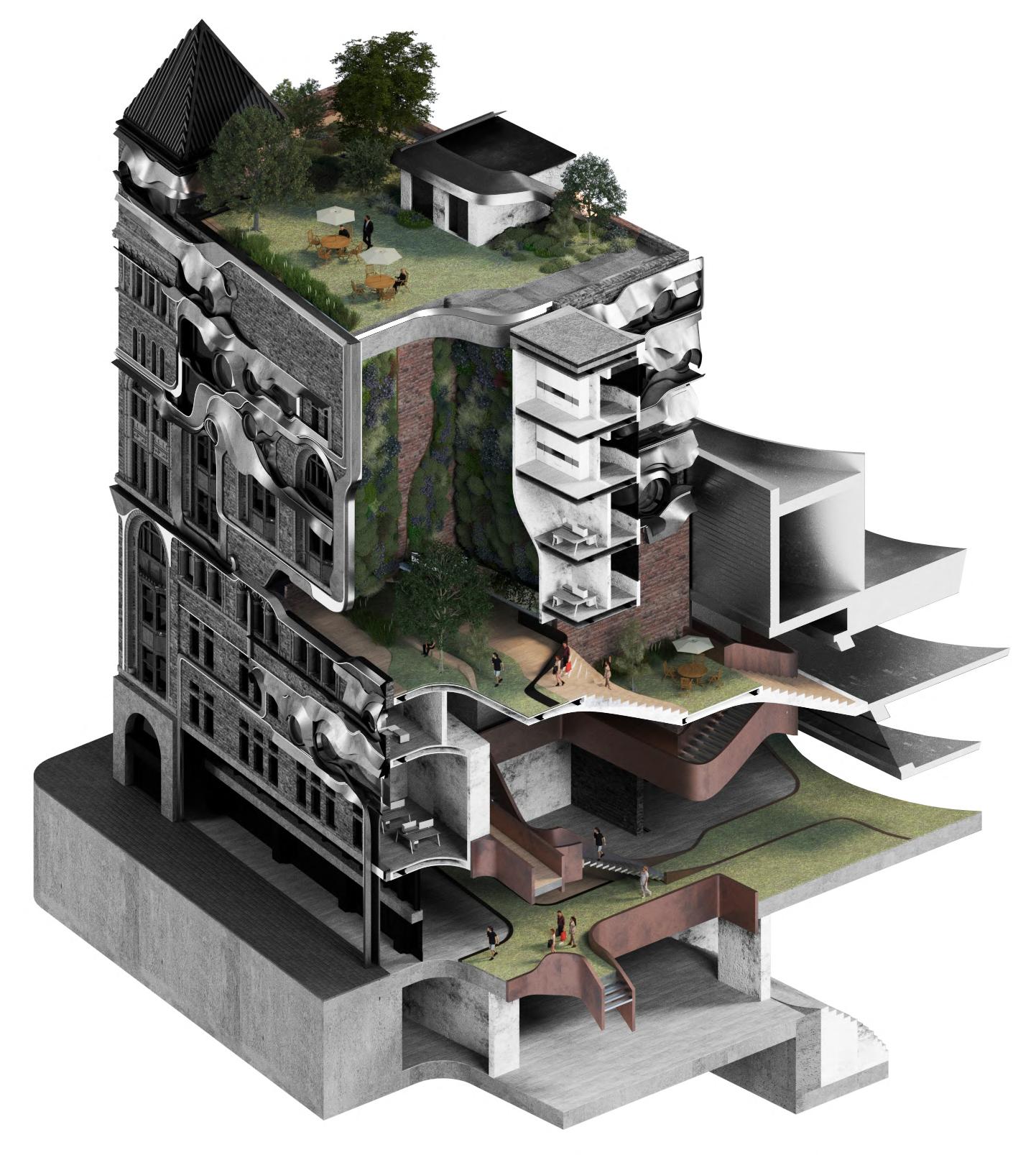
In the post-pandemic era, the shared office industry has received a huge impact. In lower Manhattan, the largest office market in the world, there are only 10% percent of workers decided to come back to the office after the pandemic, some never return. Indeed, there are many benefits working from home, but it has also led to the loss of traditional working culture, and the subsequent abandonment of many beautiful public buildings, Corbin building was one of them.
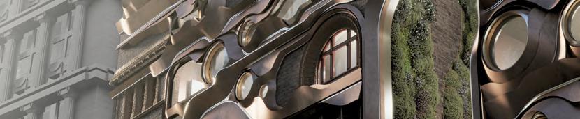
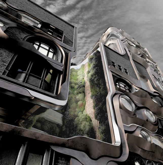
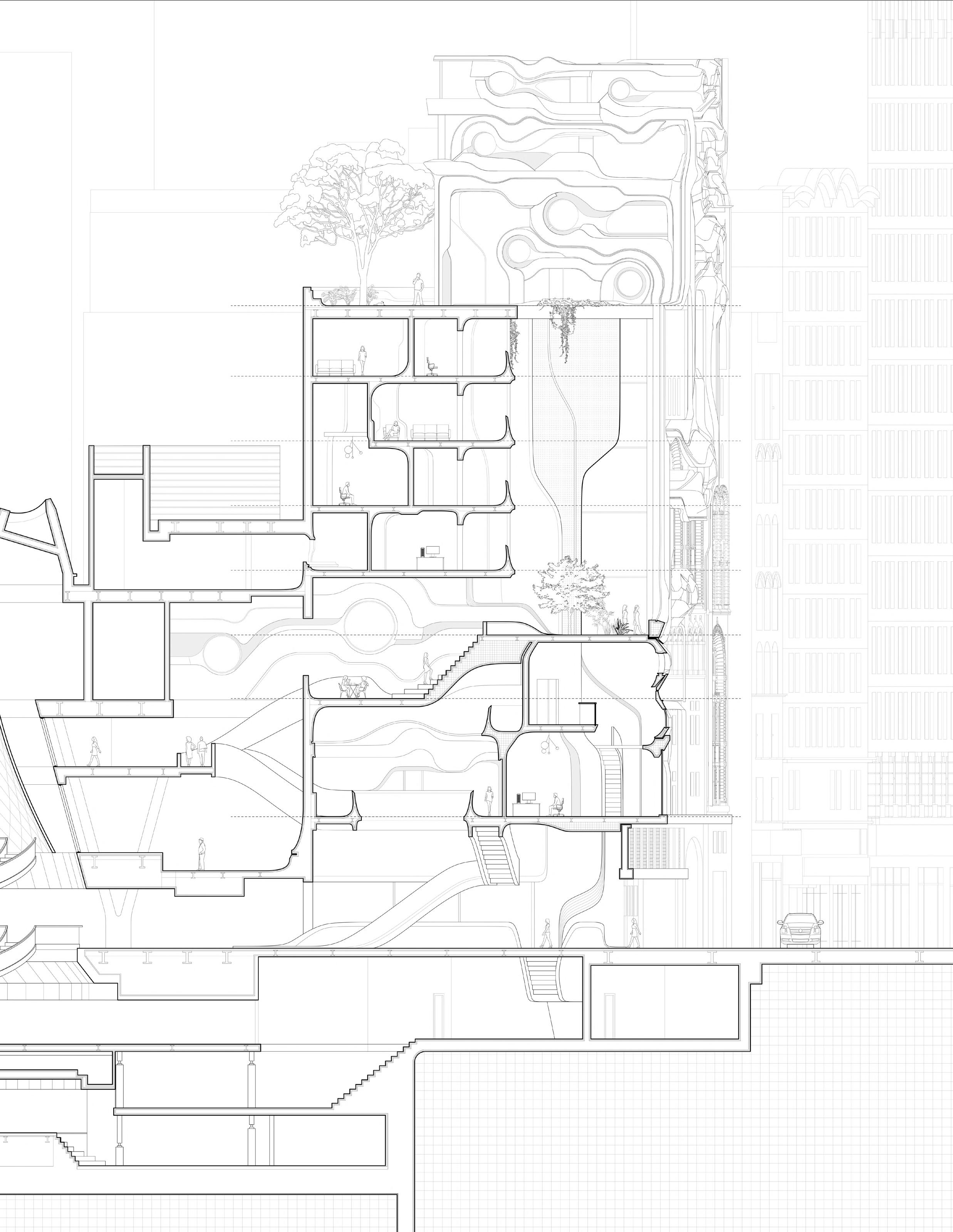
In order to repurpose these abandoned public spaces, this project re-invigorates the interesting concept of shared office. By creating an urban void within the clusters of mixed residential and office units, the project share and take advantage of the huge traffic coming from the Fulton center, introduce them a hydroponic garden that re-occupies the Corbin building from bottom to top, merging the shared offices into this part of the urban landscape.
In the research study phase of the project, inspiration was taken from the natural behavior of lichens. The idea of ‘clustering’ was extracted from the study and applied to the formation of the units.
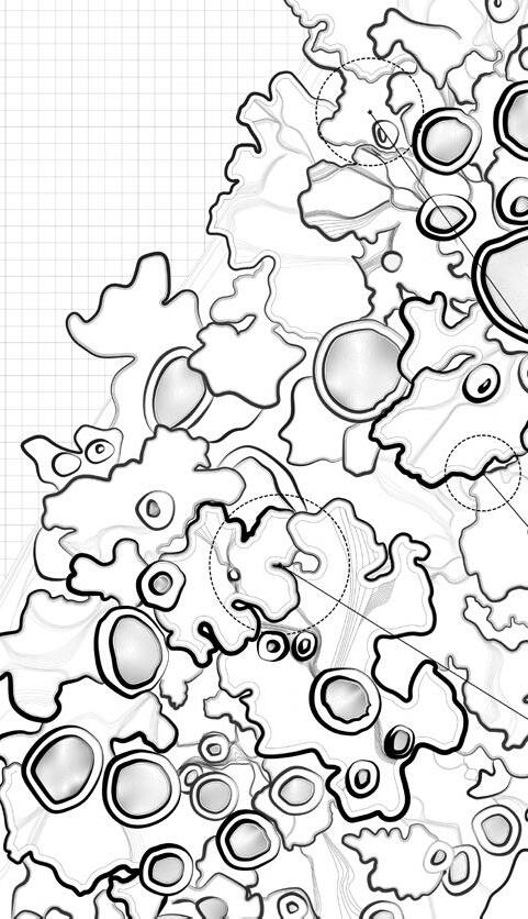
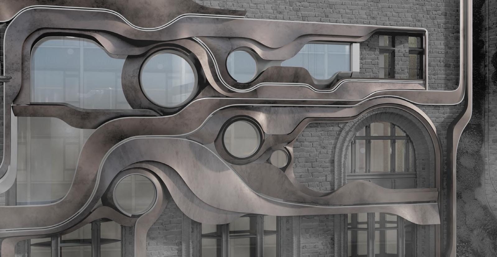
The units are also organized under the rule of clustering. Each clusters consists a large unit in the center, and a several smaller units surrounding it. On the edge of the clusters, voids are created for the shared offices and public common spaces.
circulation and public spaces 2. setback and courtyard
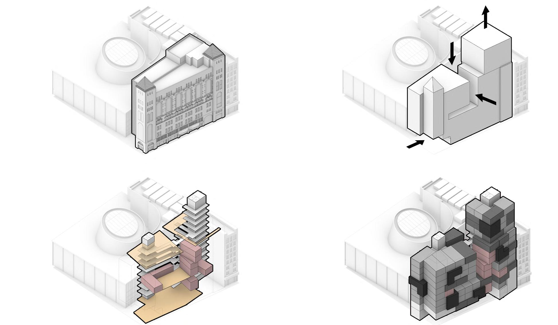
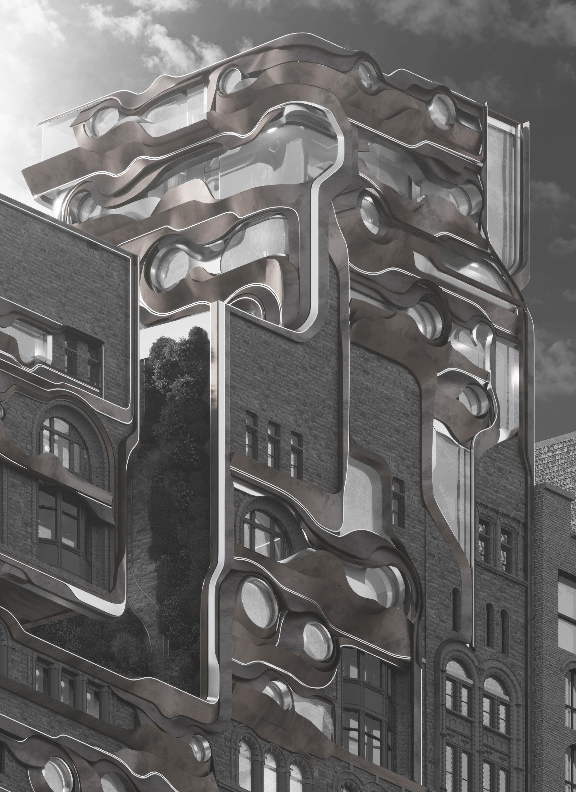
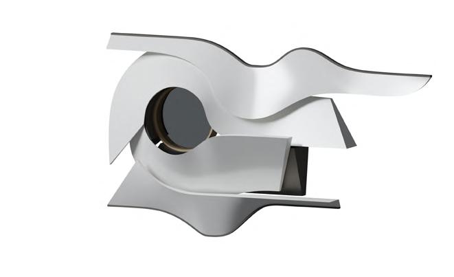
Within the clusters of units, each units relate with each other follows the rule of pushing. When units meet each other on the edge, the reaction between them cause distortion, resulting different types of shared spaces between units.
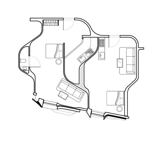
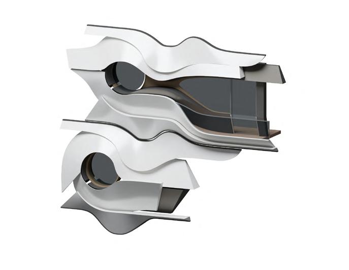
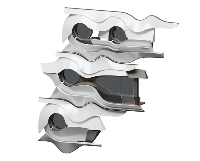
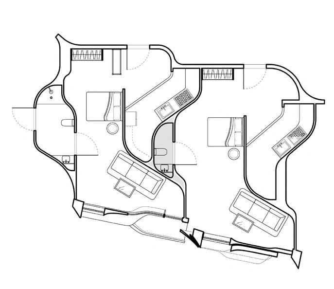
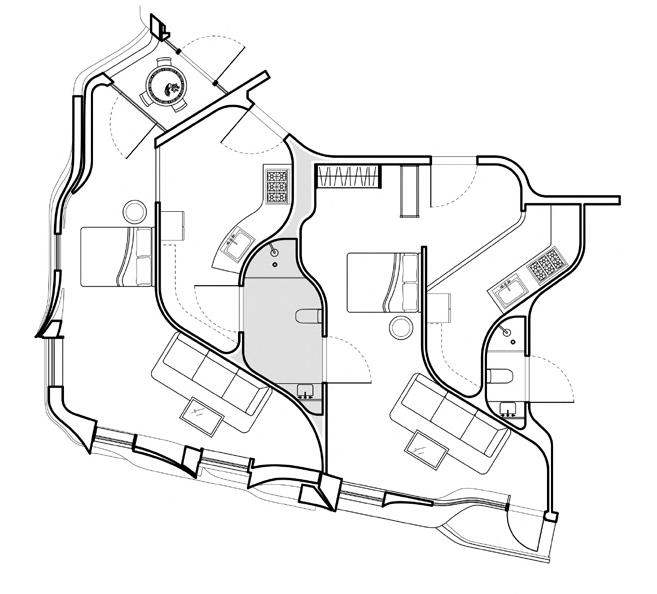
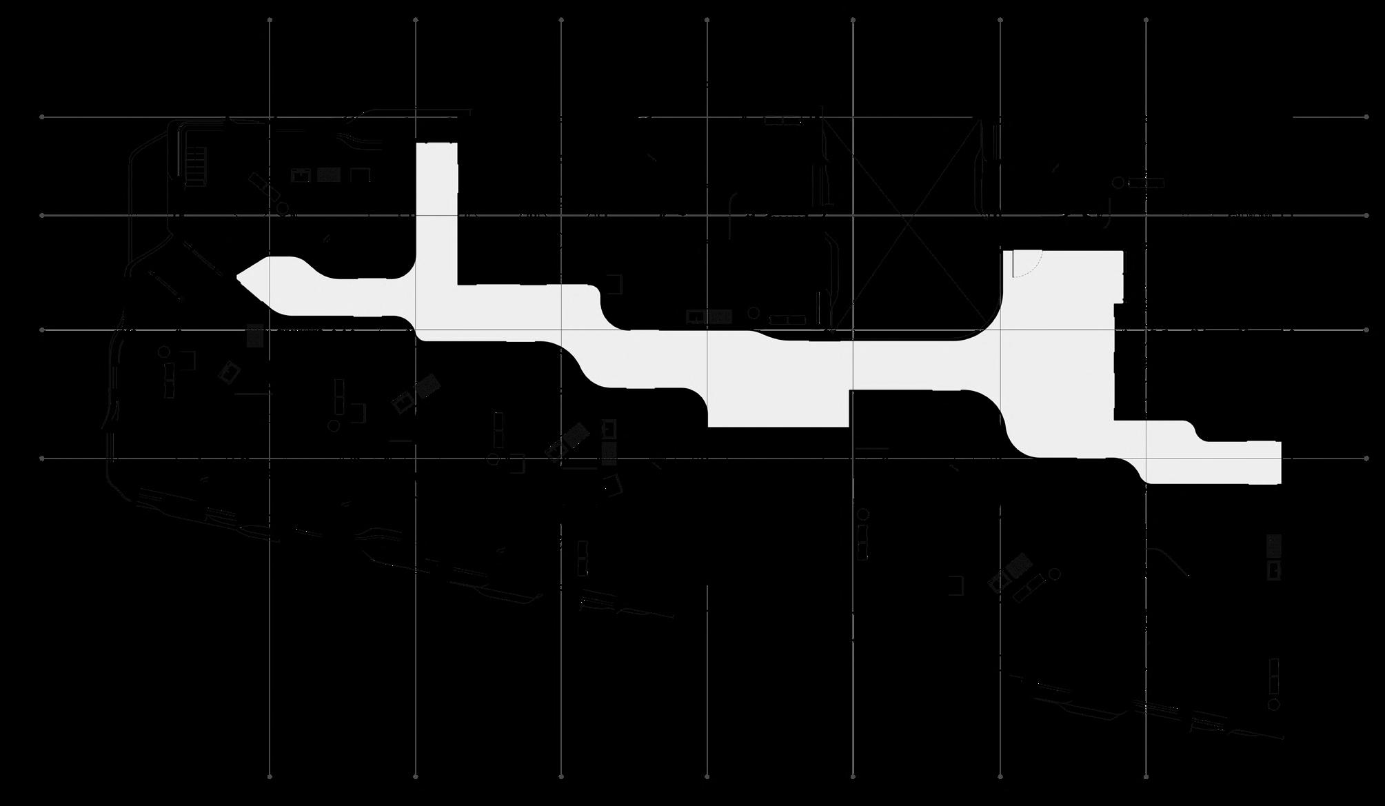
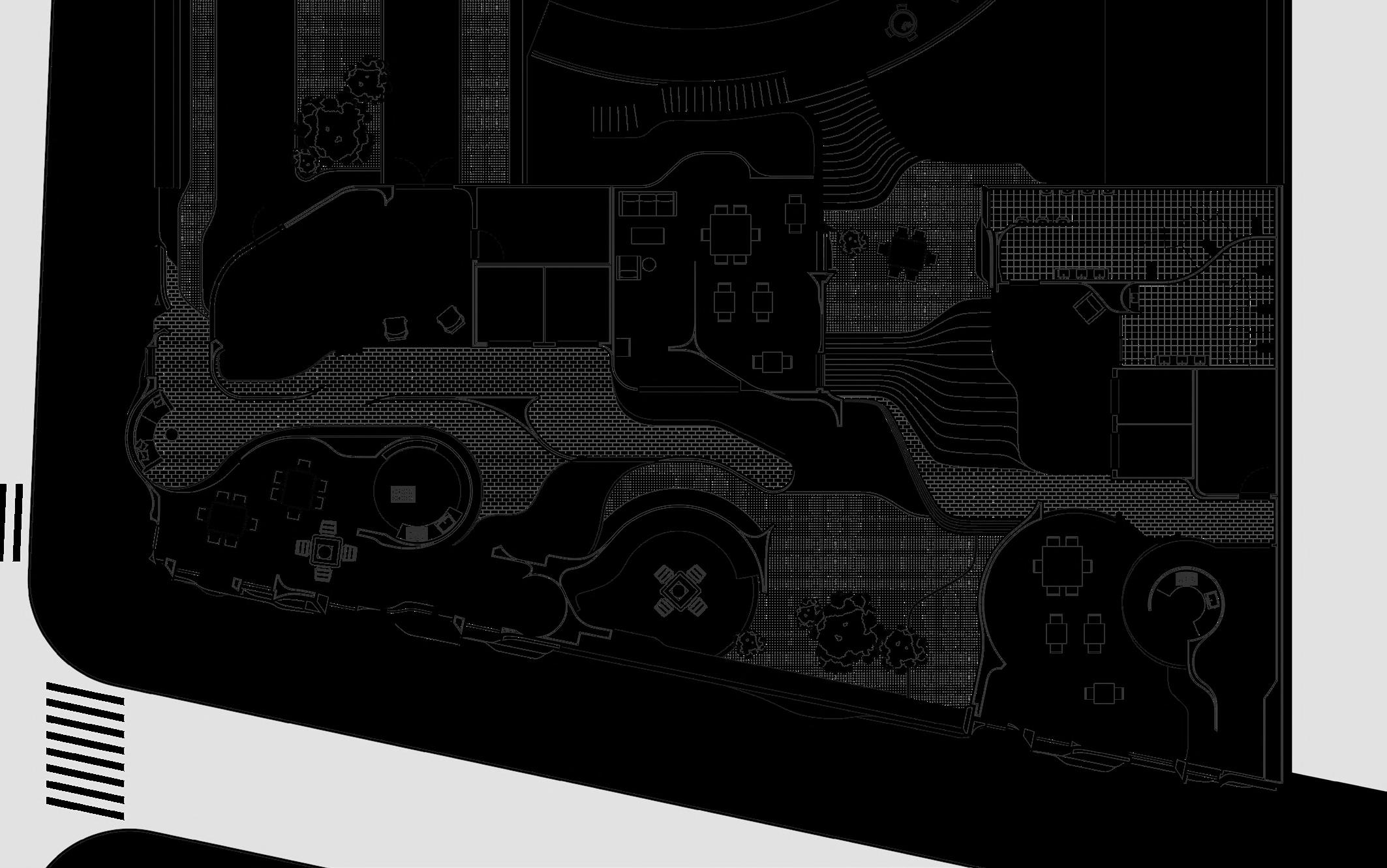
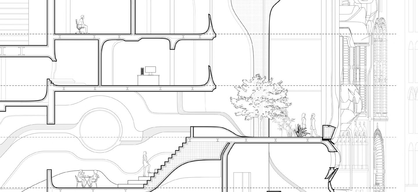
At the 6th floor of the Corbin Building, where clusters of units and offices are creating a gap between each other, an open floor plan with public lounges, meeting rooms, outdoor gardens is proposed, this floor is also making connections to the adjacent fulton center.
On top of the original Corbin Building, an additional tower is added to the existing units to emphasis the idea of clustering.
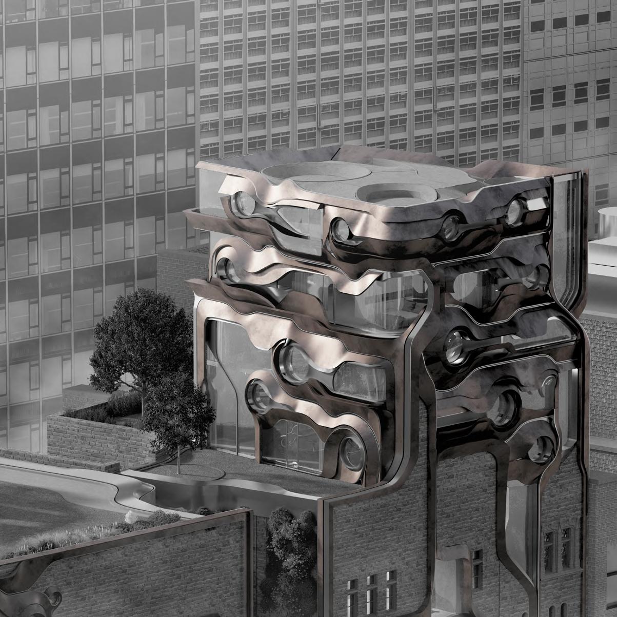
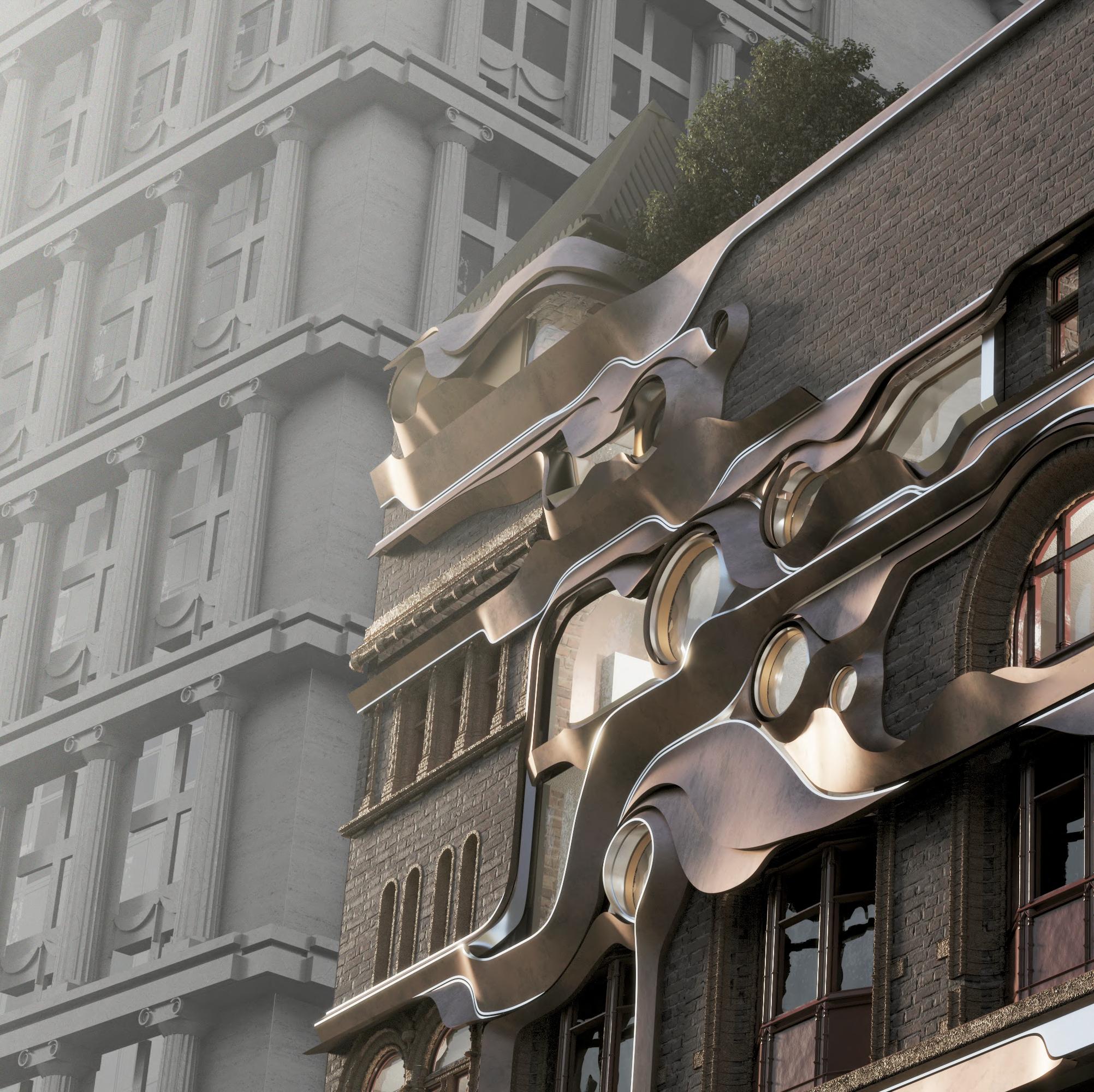
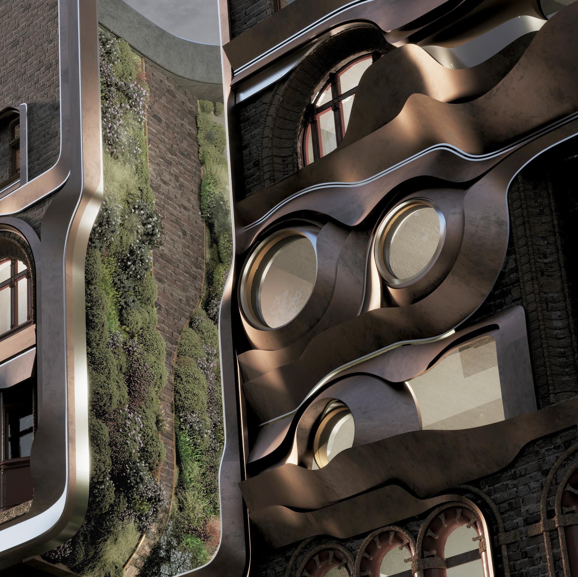
Foot traffics from the Fulton center and the street are introduced to the Corbin building through a continuous greenway, it gives a hint of the gardens inside the building.
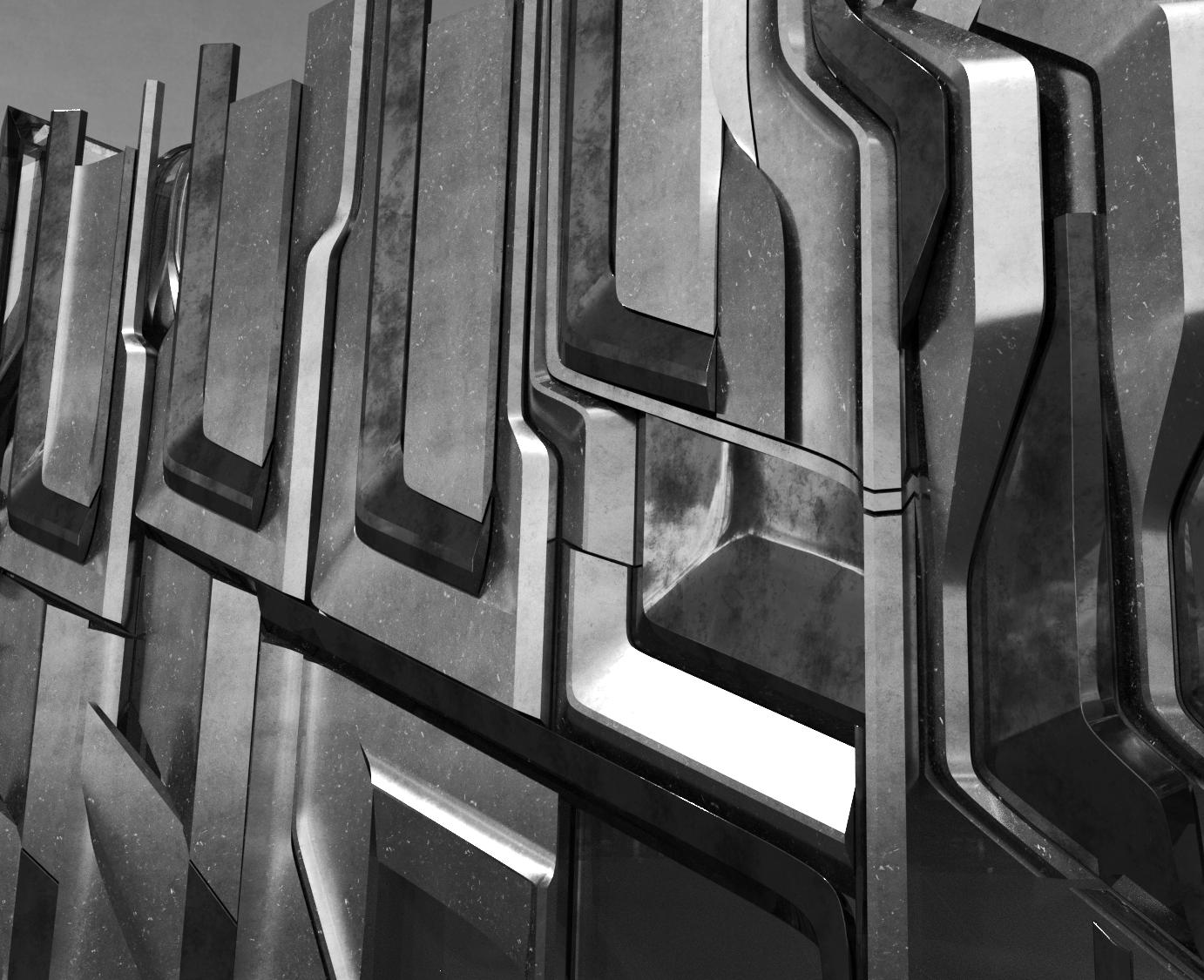
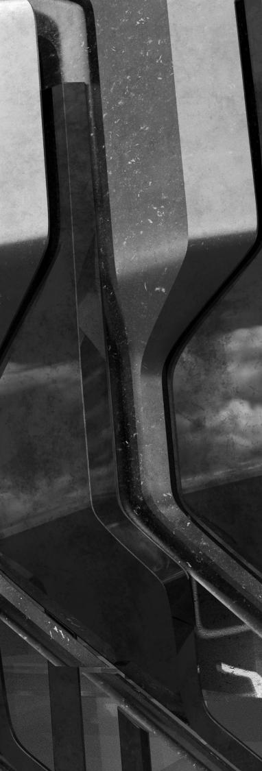
Museum Extension
Arch 602: Expansion of the New York Historical Society
Location: 170 Central Park West, New York
Instructor: Kevin Cannon
Team Member: Chongyan Chen, Boyu Xiao
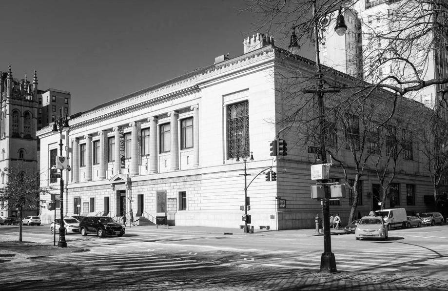
The New York Historical Society is a Beaux Arts style building, which was characterized by a highly enclosed structure and crowded interior spaces. It appeared disconnected from the cultural background and folk society of New York, making it challenging for urban residents to establish a meaningful connection with the museum's interior.
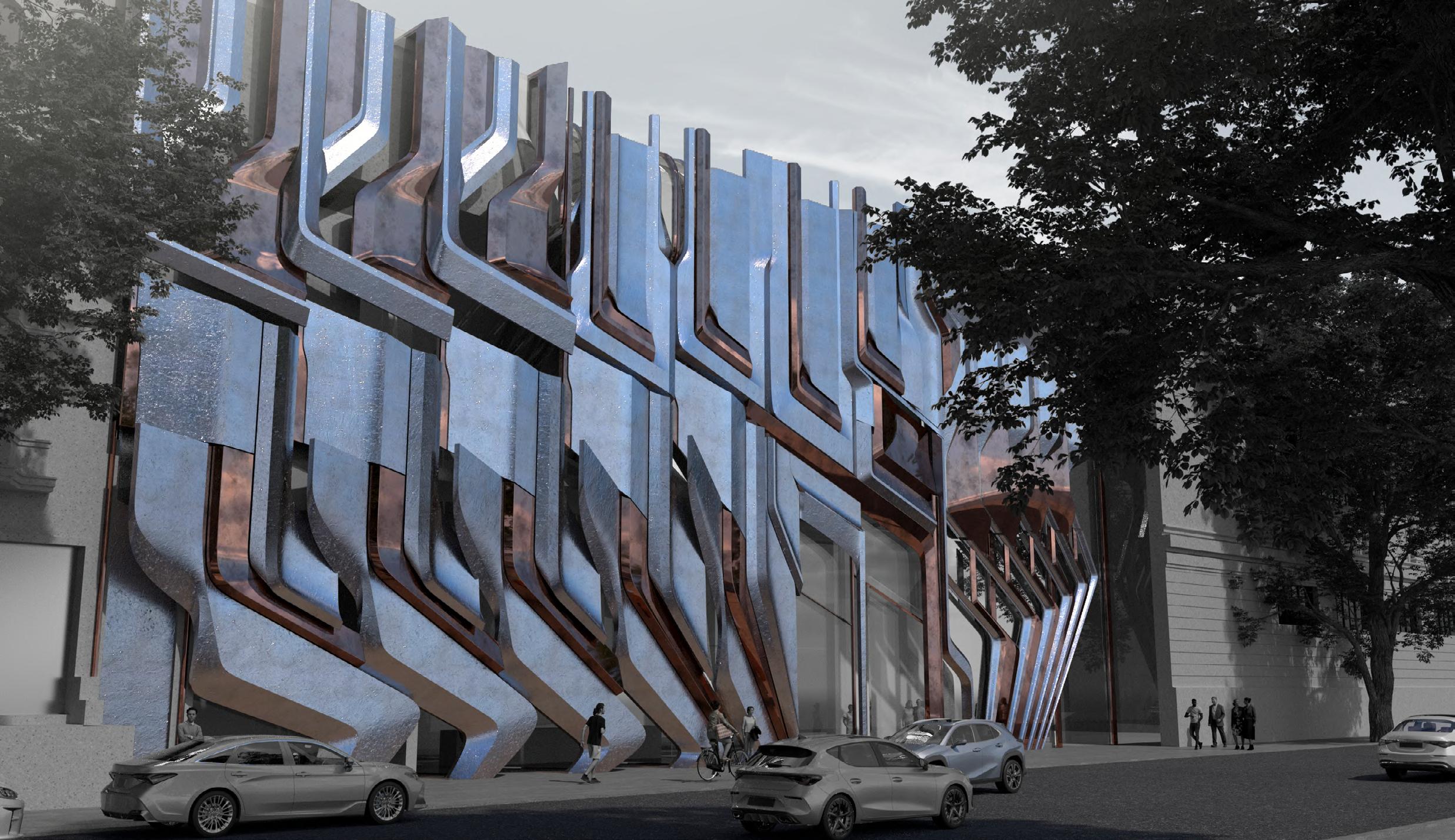
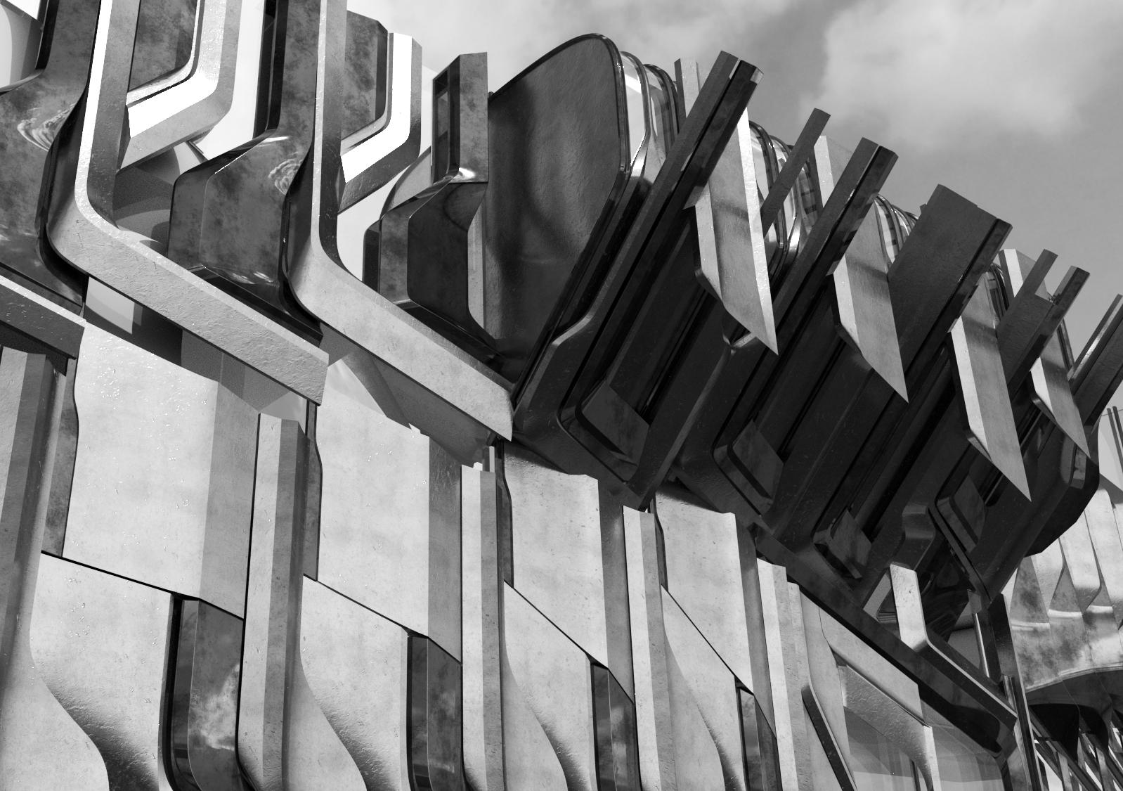
Therefore, we consider the extension part a Juxtaposition of the original structure, by employing an intense language that conflicts with the original site, and complemented by a flexible and transformable structure, our intention is to open up this art museum and establish visual and multisensory connections with pedestrians, thereby transforming the existing architectural and cultural allusions of gentrification in New York.
The idea of the museum extension is to serve the community better as it should, not only for those people bought the tickets. Therefore, mutiple transformable structures has been applied to the facade, making connections between the street and the museum extension.
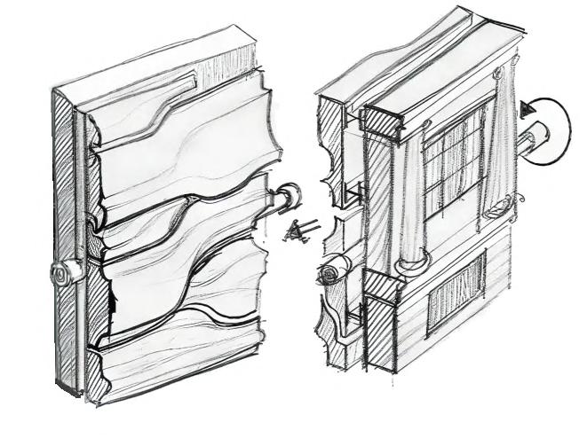
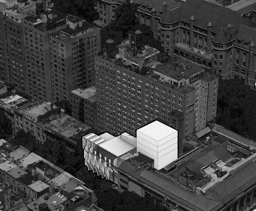
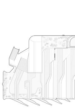
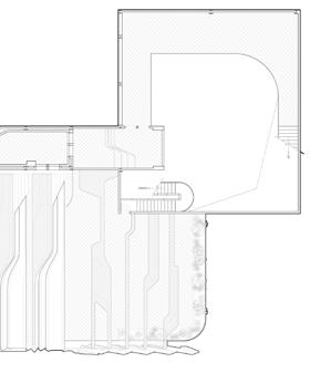
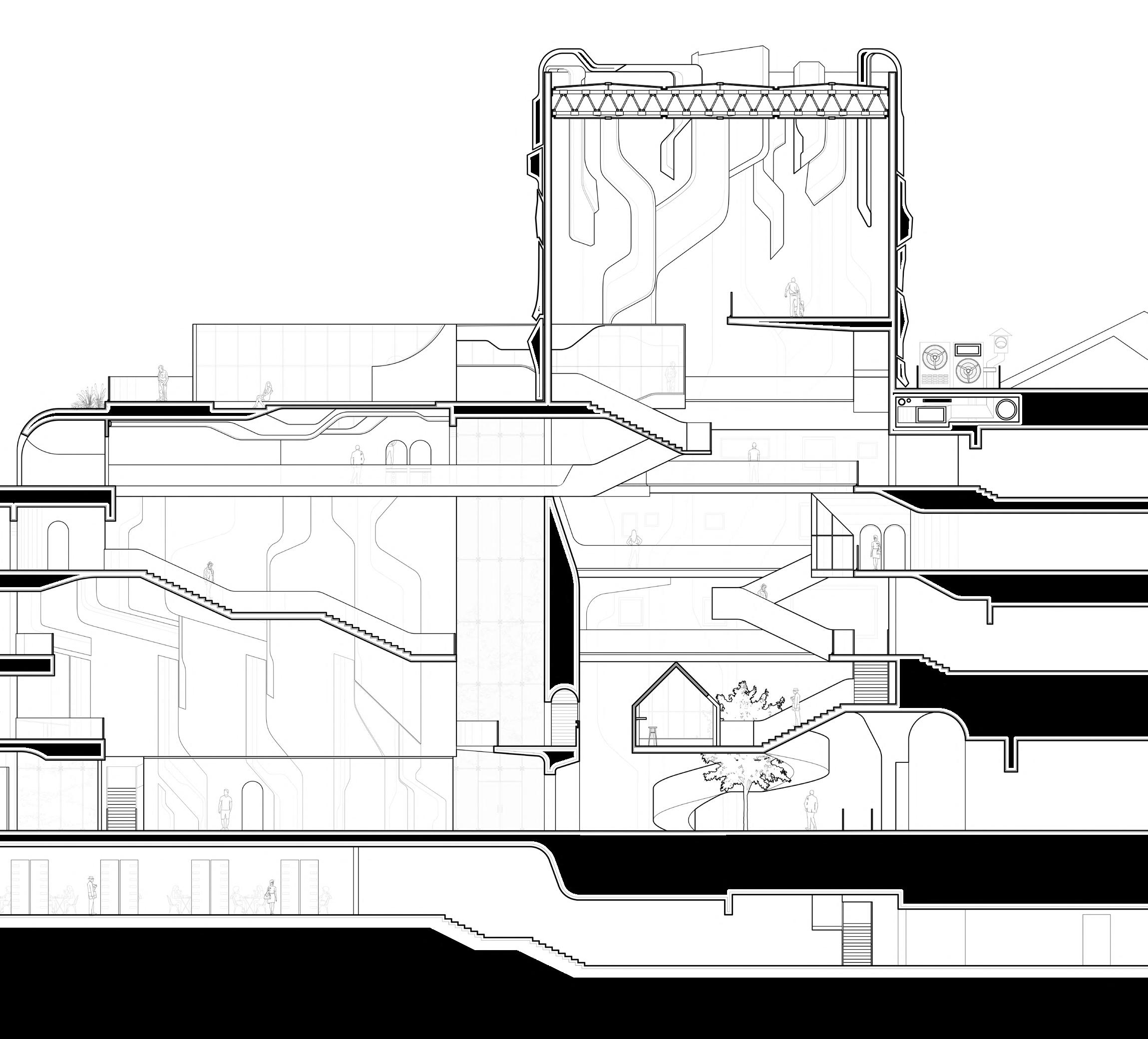
The idea of the museum extension is to serve the community better as it should, not only for those people who bought the tickets. Therefore, mutiple transformable structures has been applied to the facade, making direct connections between the pedestrians and the museum.
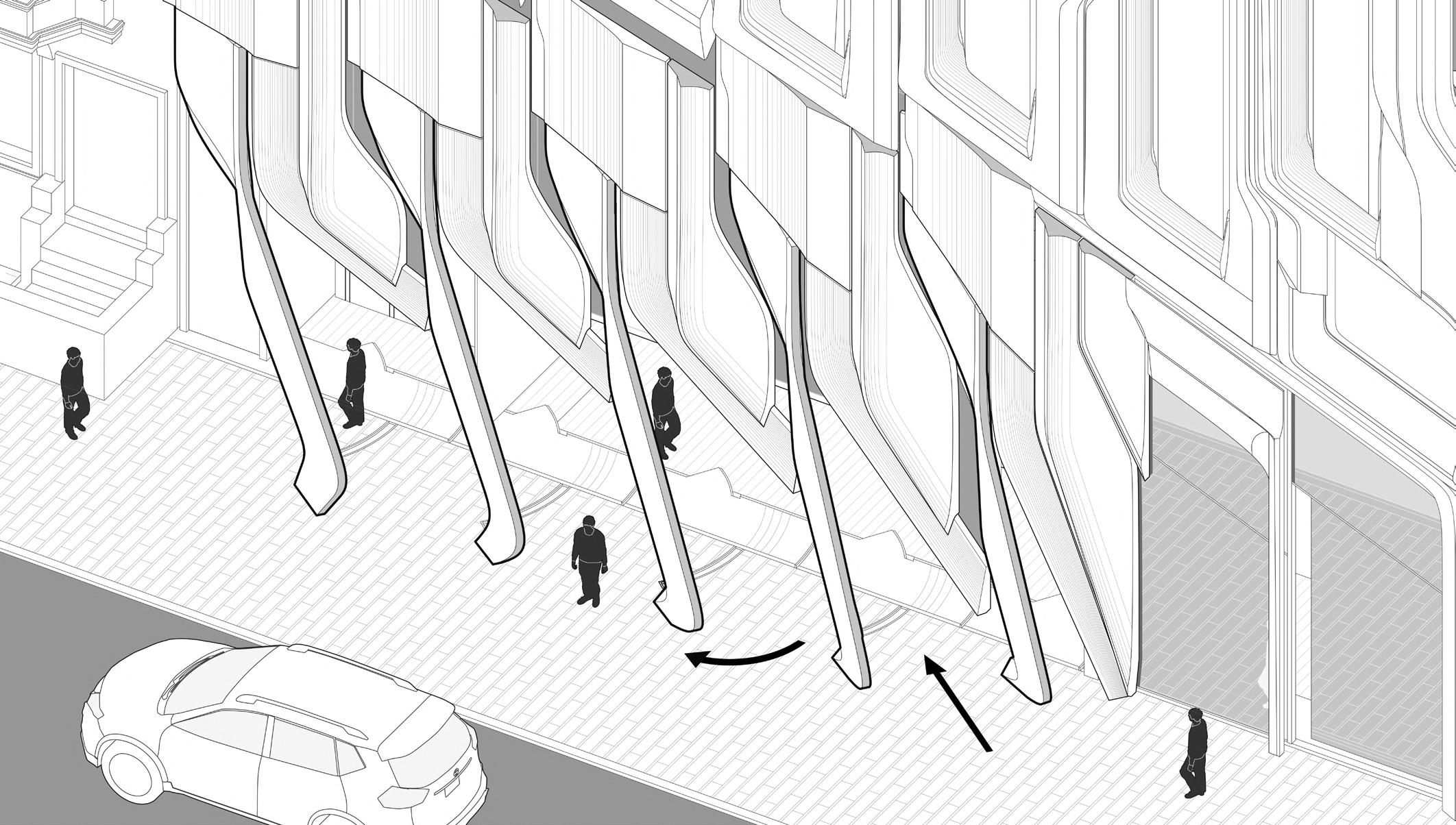
Axonometric drawing of street entrance, facade panels opened First floor of the gallery become part of the street
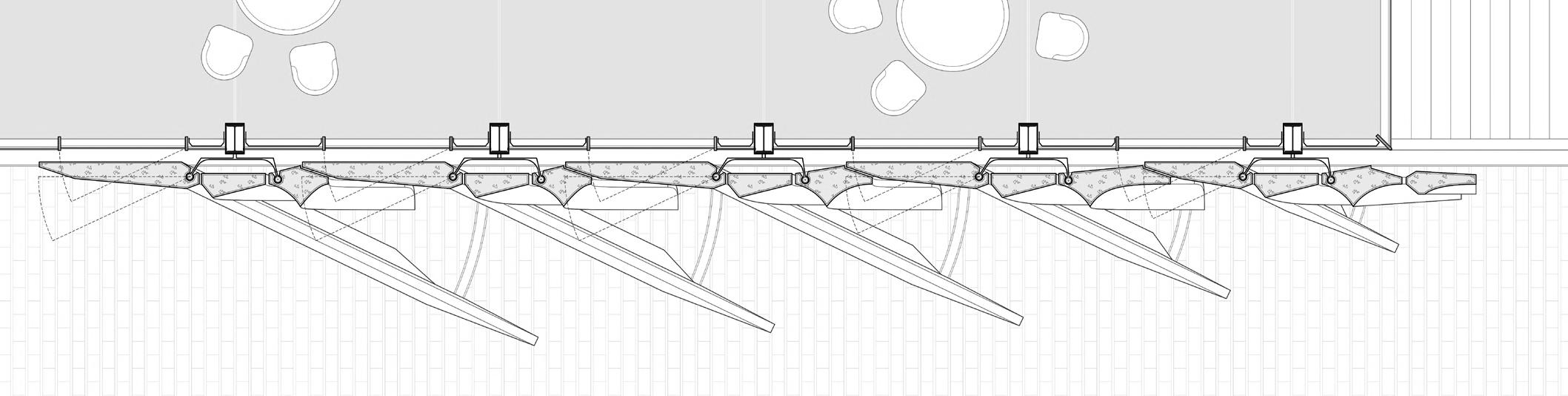
Plan drawing of the first floor facade panels Movable panels are connected to the columns
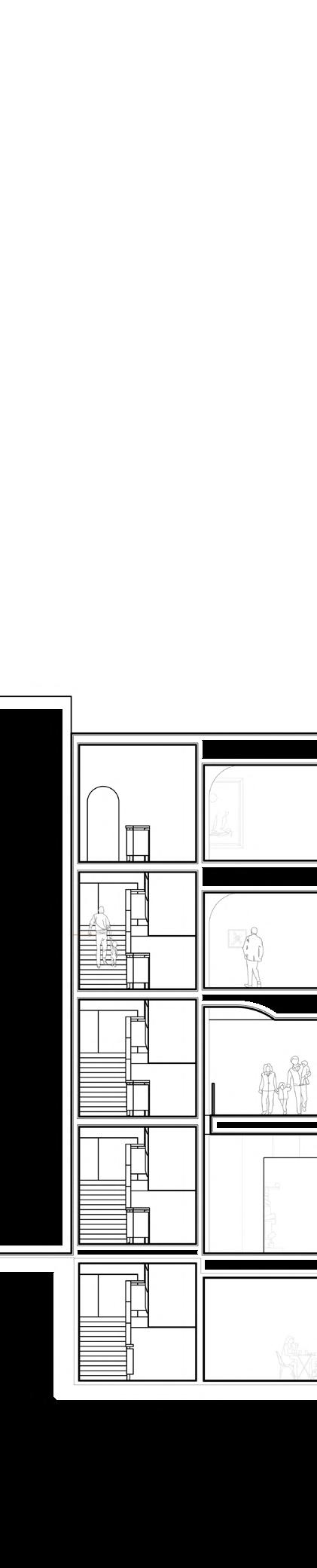
Section looking towards Central Park
1. Extendable theatre
2. Elevator gallery
3. Street gallery
4. Extendable gallery
5. Archive Extension / Library
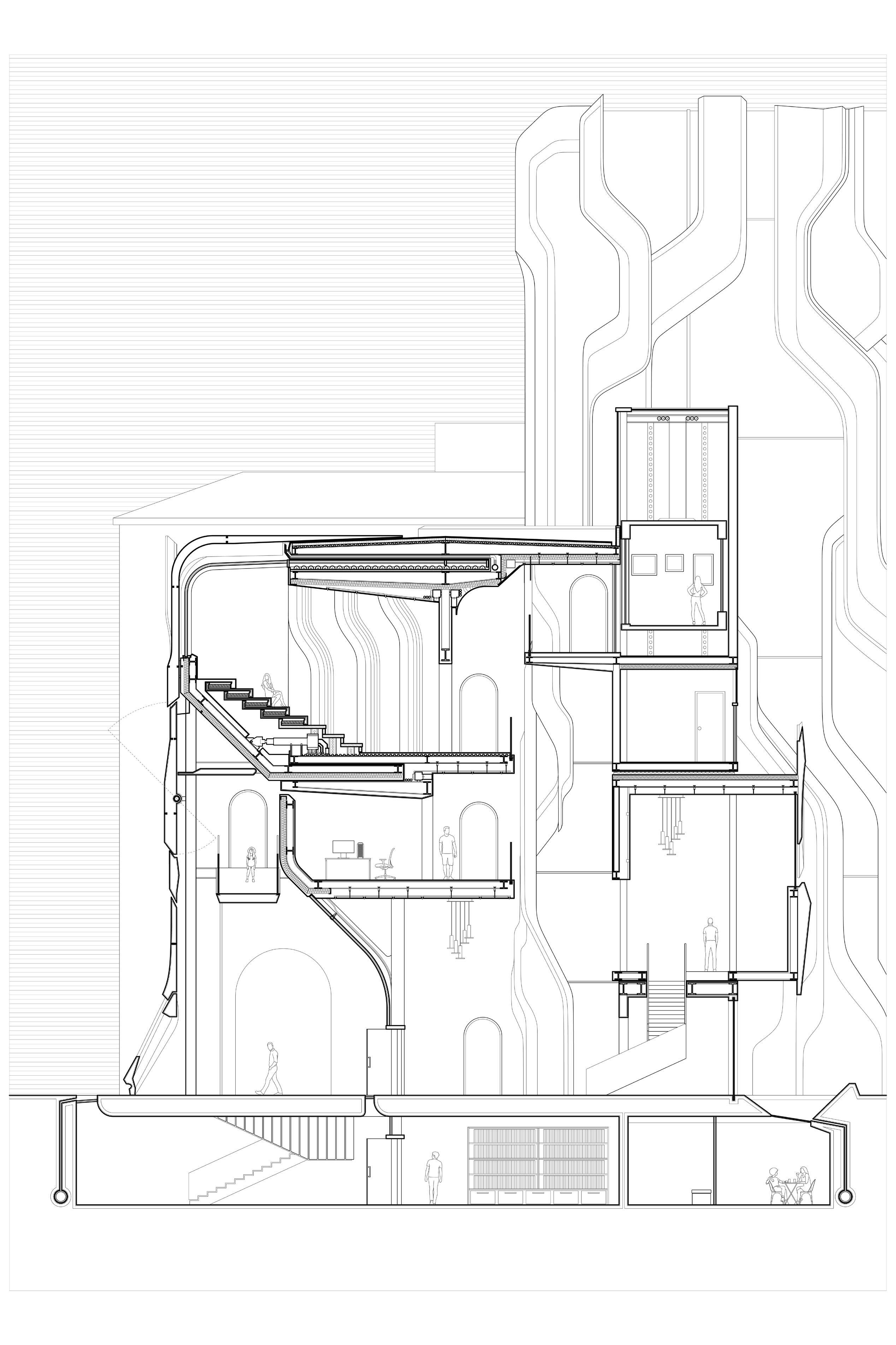
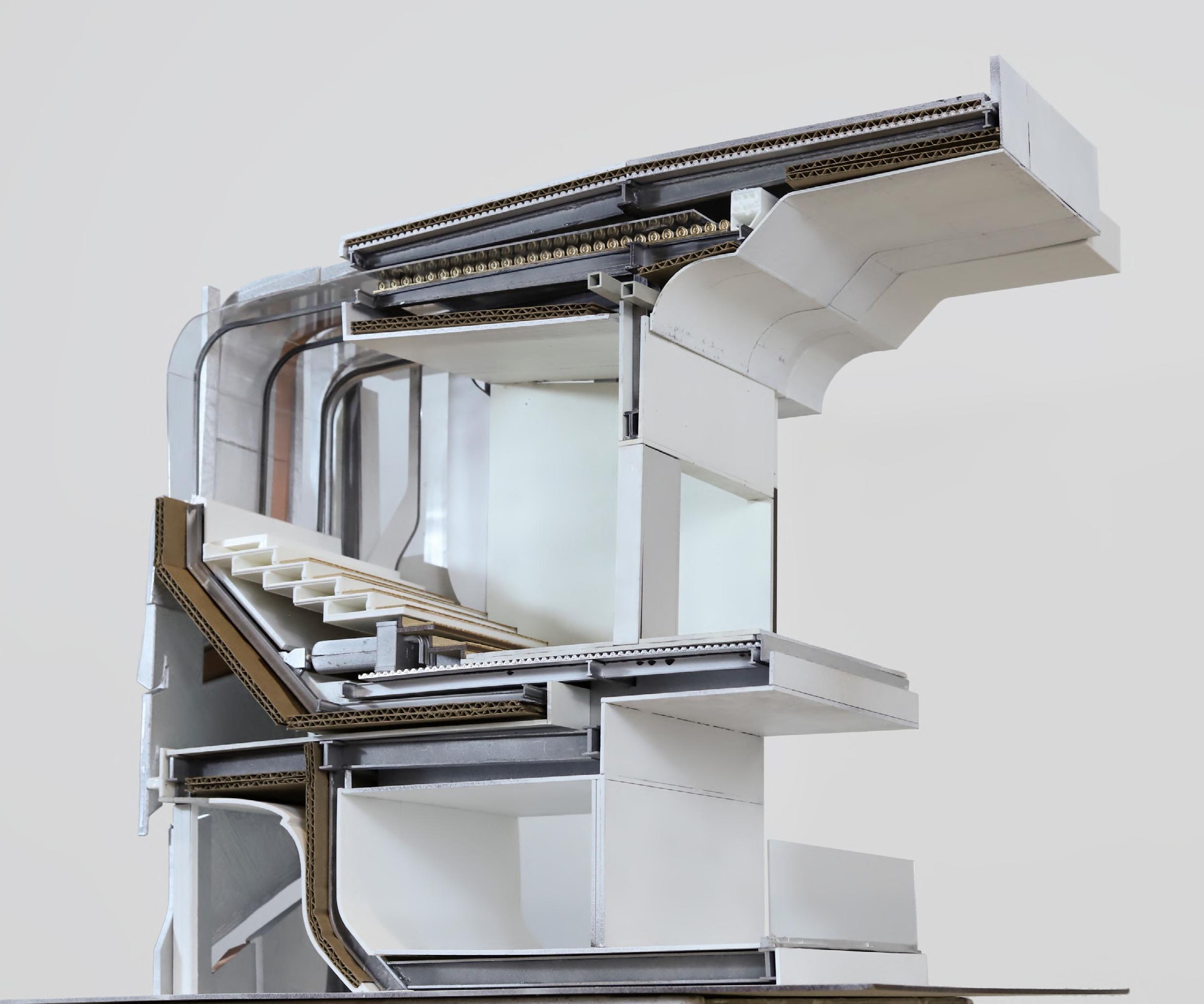
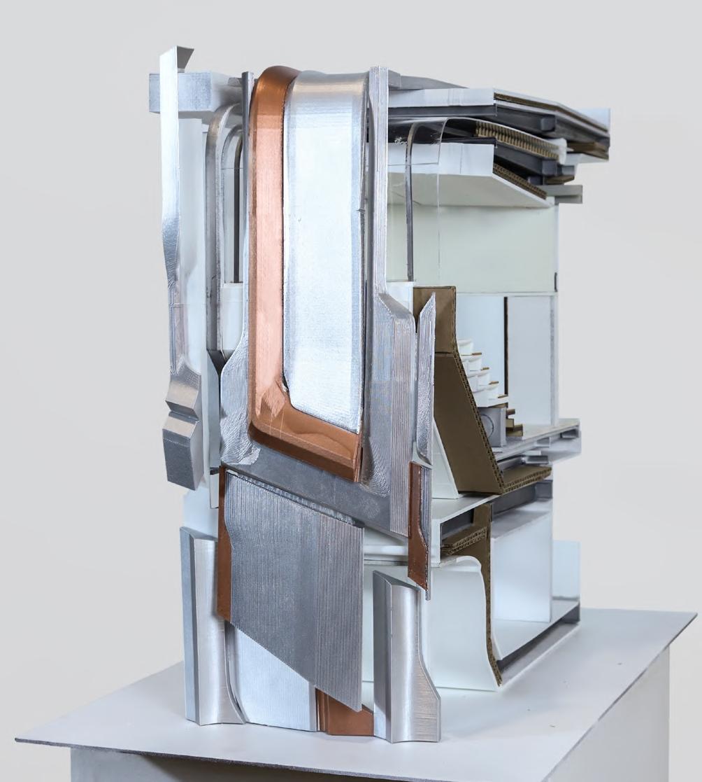
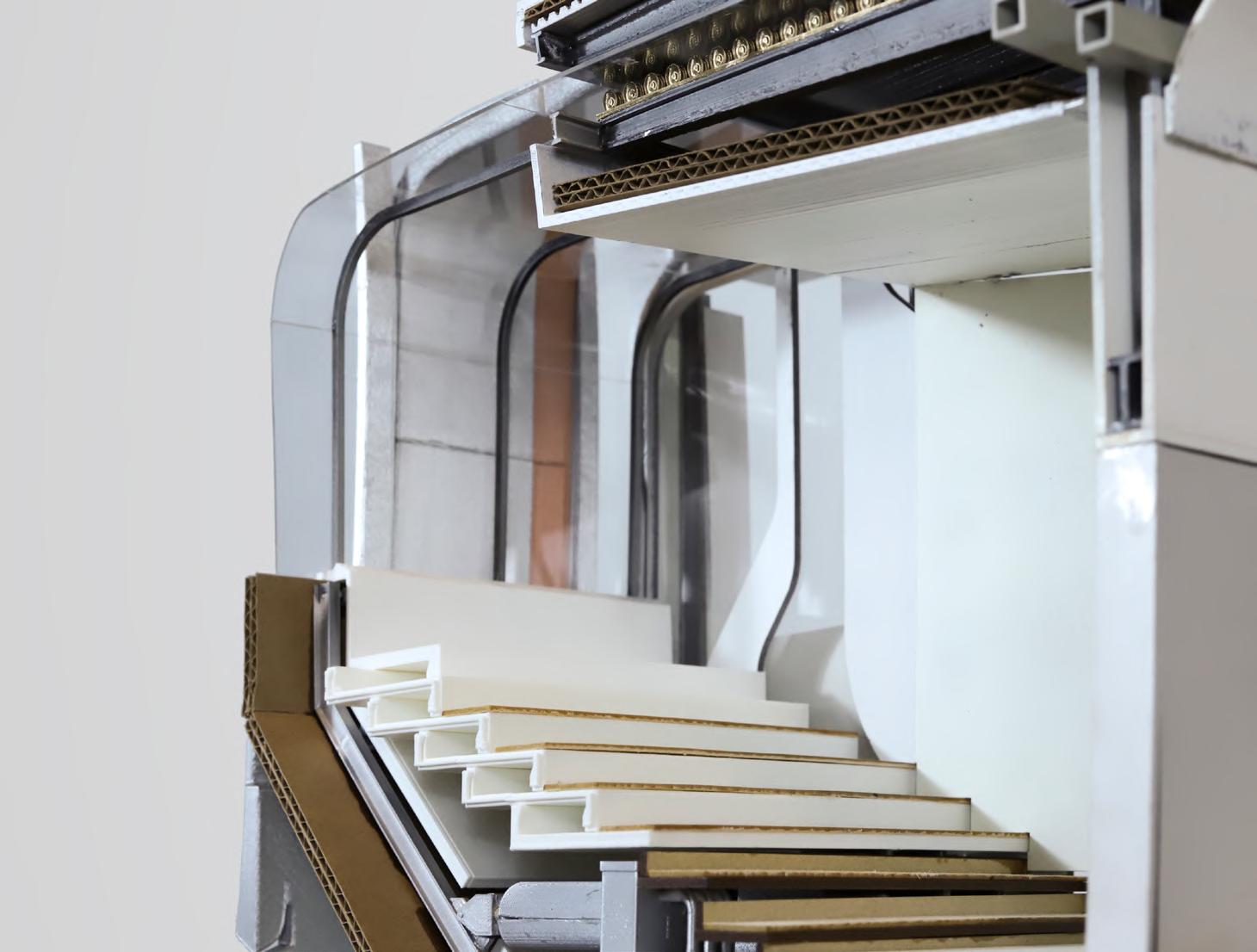
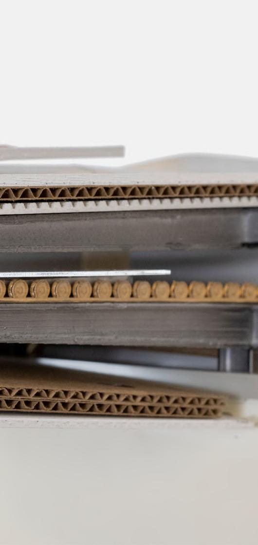
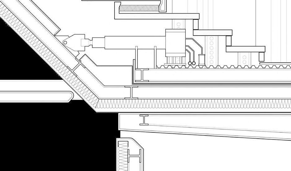
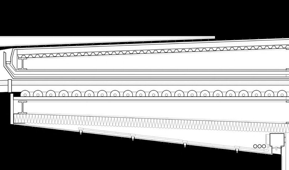
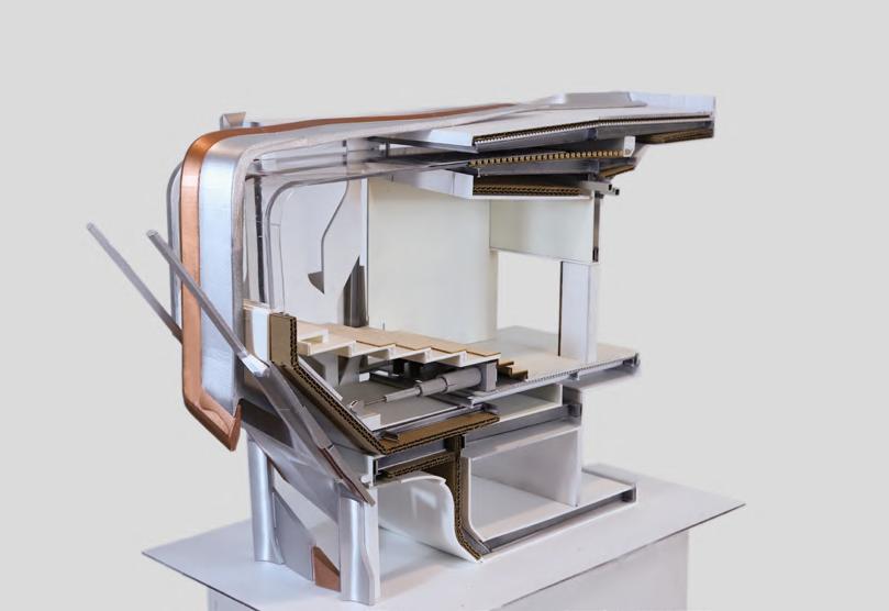
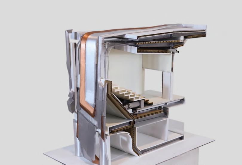
To design a movable structure, gravity is not the only challenge, the moving mechanisms created a lot The connection between movable and immovable parts can cause many problems such as waterproofing. details of the drawer have been specially designed to cope with these issues.
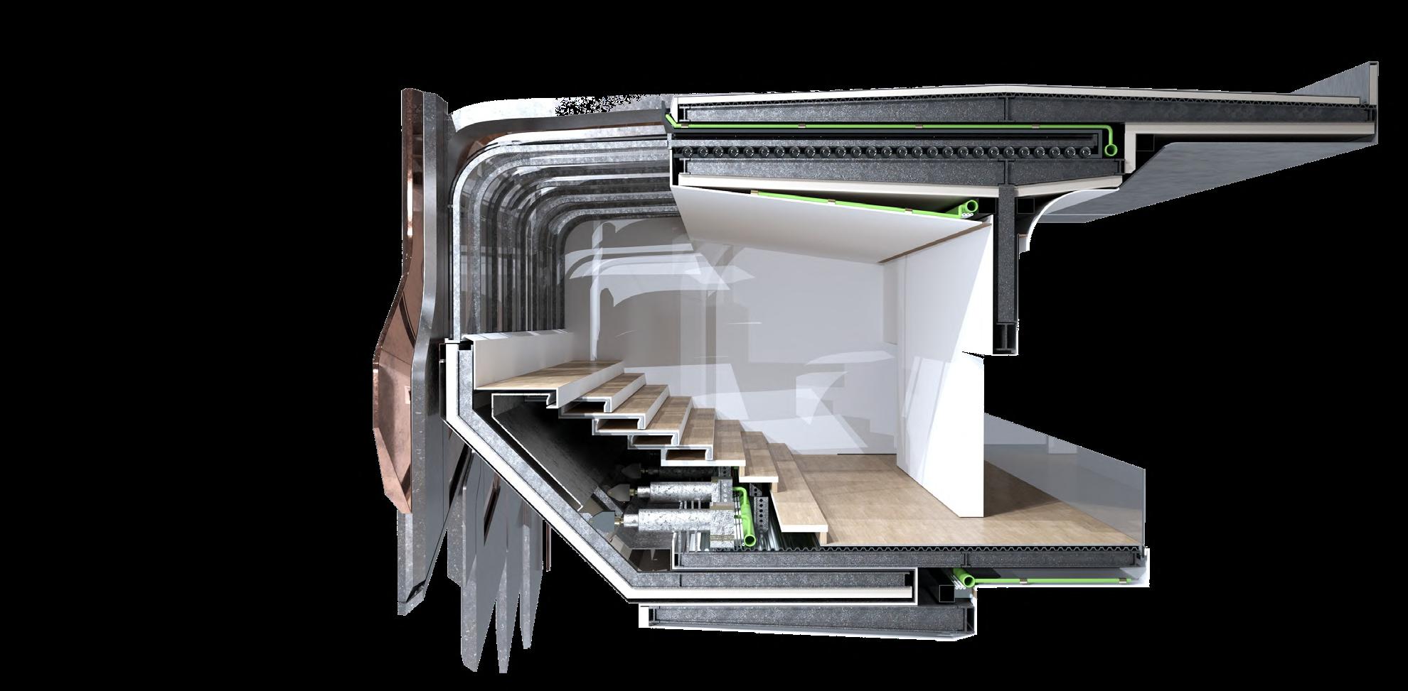
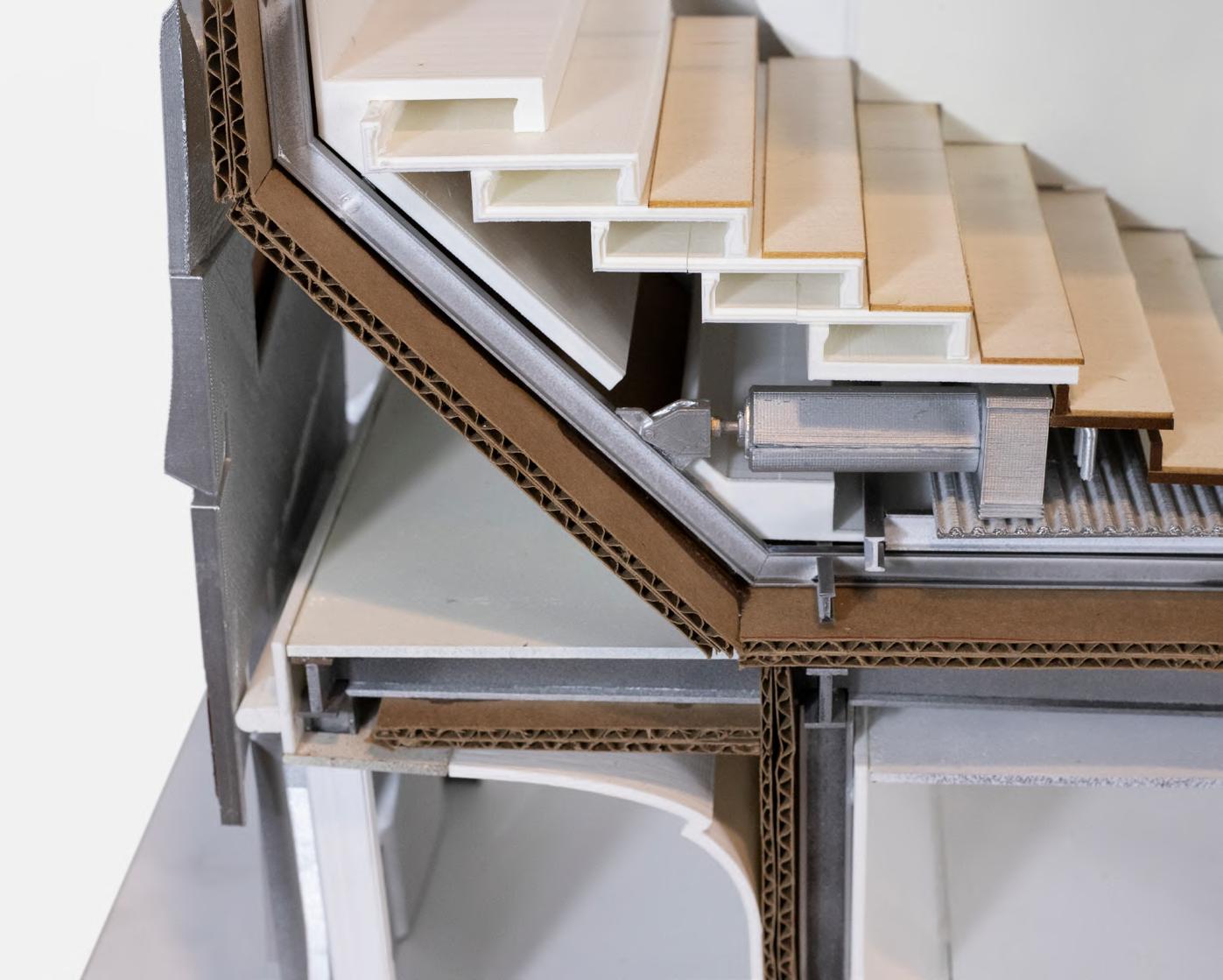
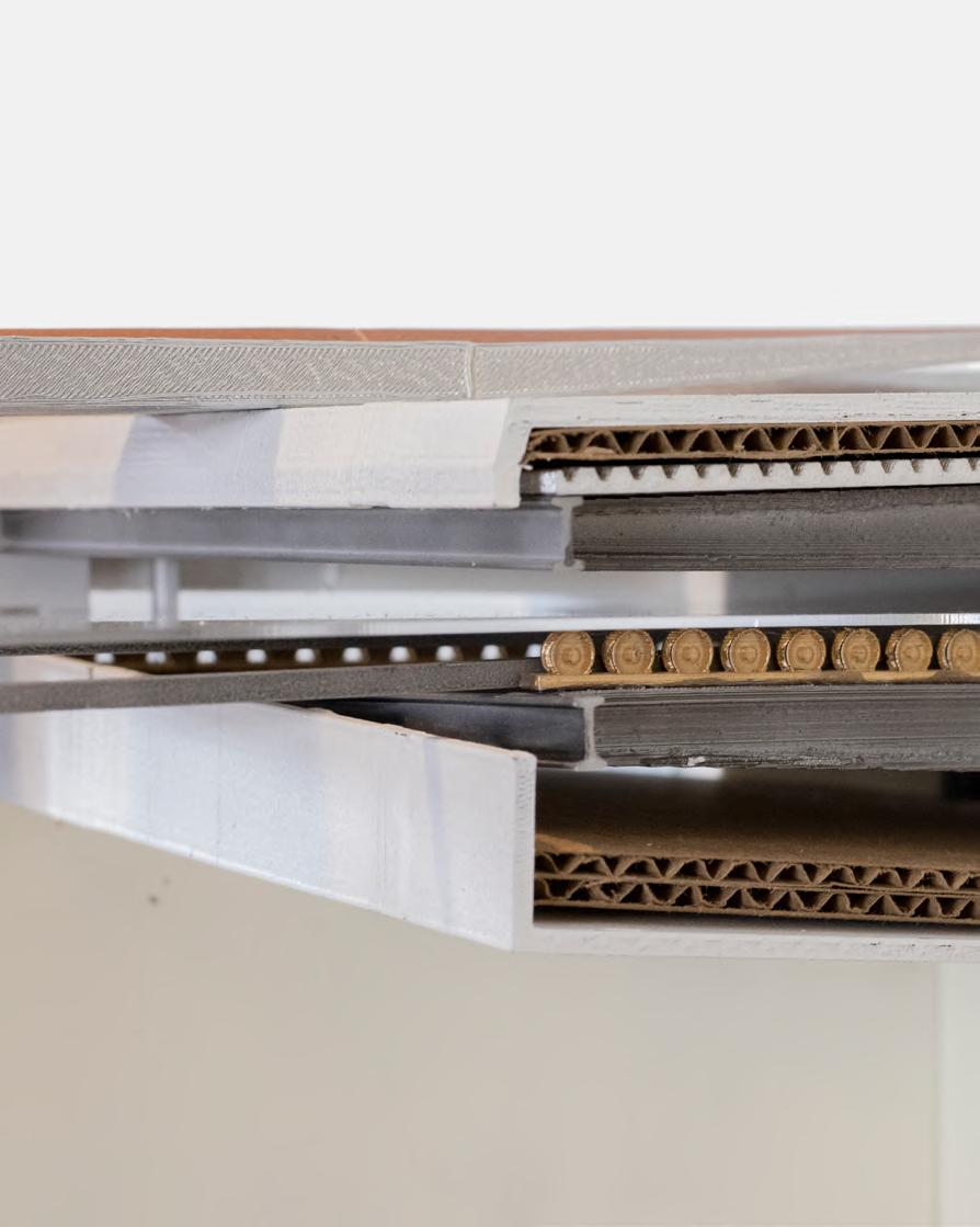
of weak spots on the structure. waterproofing. Therefore, the structure and
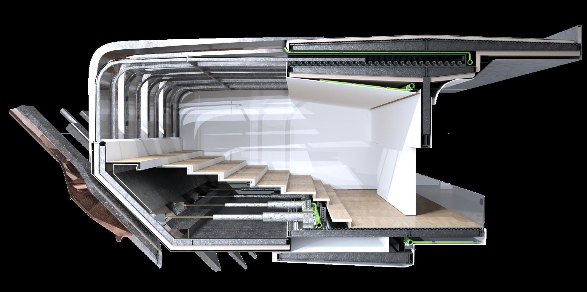
Practice of parametric analysis and design, robotic arm coding.
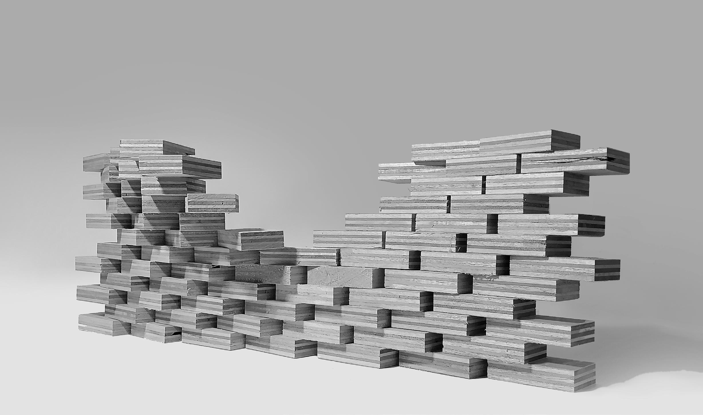
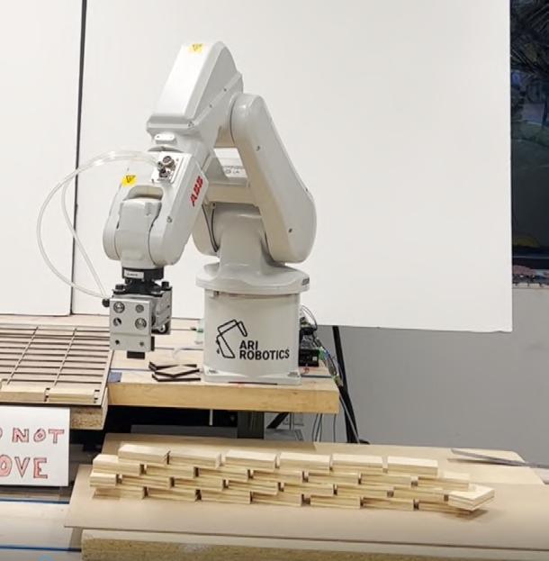
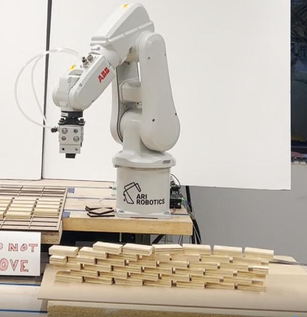
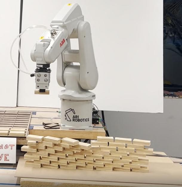
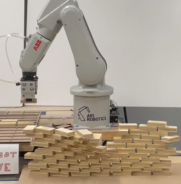
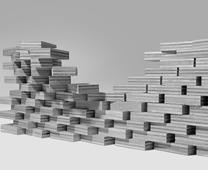
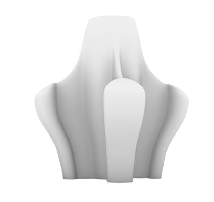
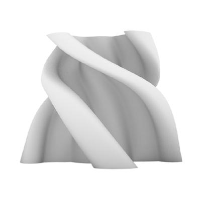
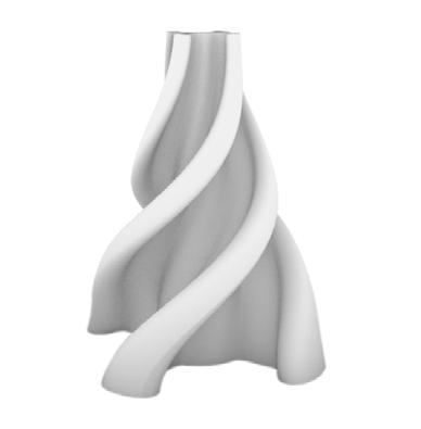
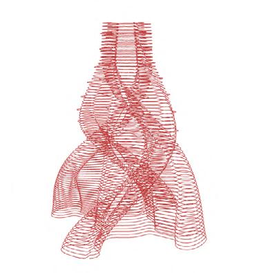
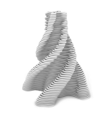
This practice aims to use a simple base surface to generate an unique brick wall pattern and its tool path, also simulation of the walls durability before actual printing.
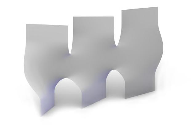
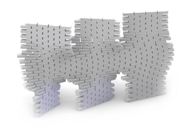
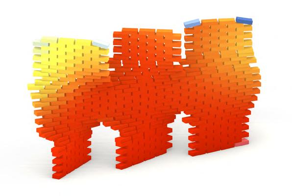
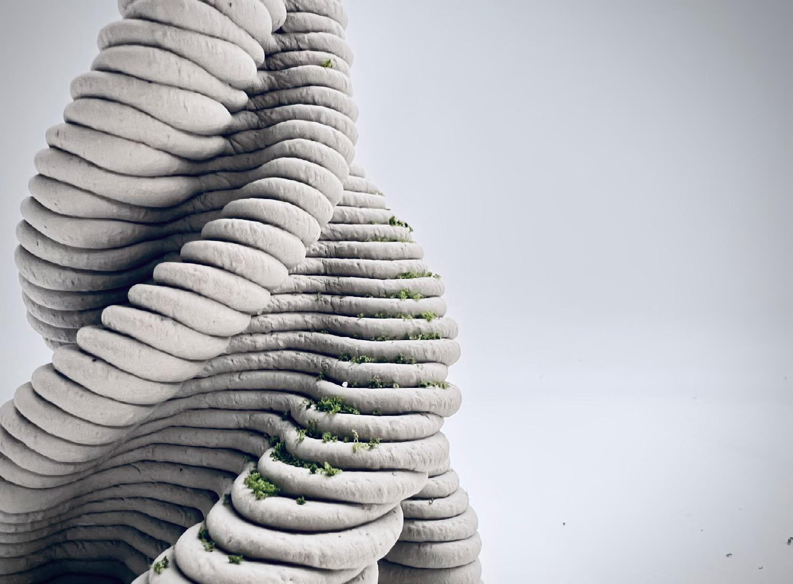
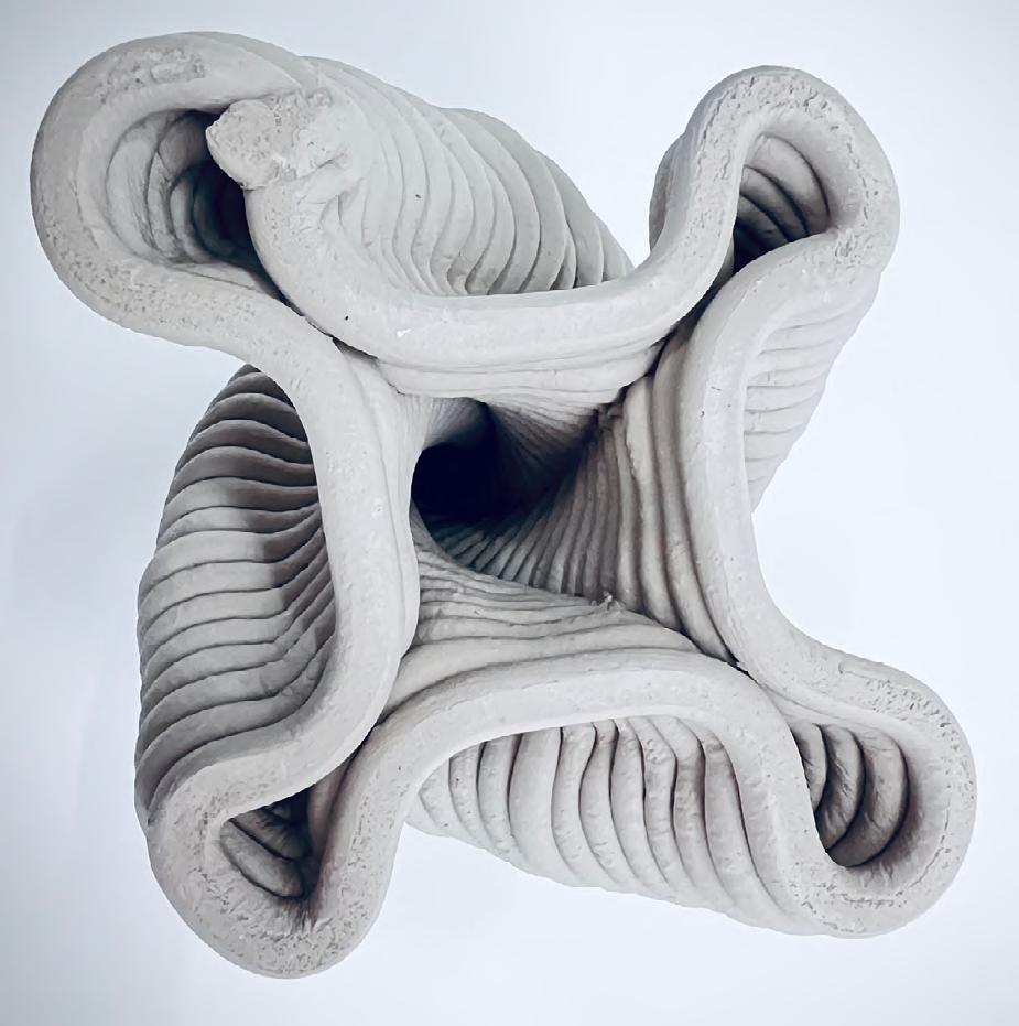
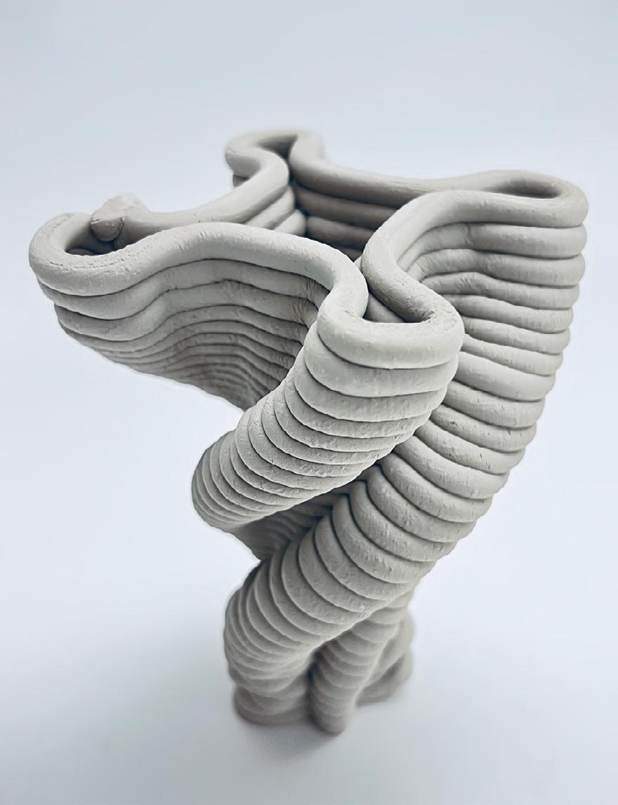
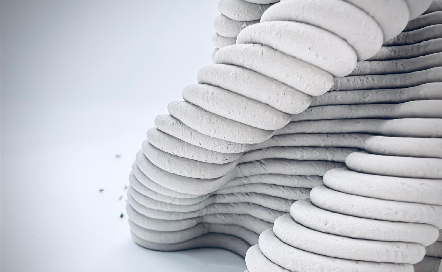
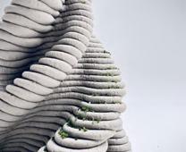
This practice tests possibilities of feasible geometries using concrete 3D printing, multiple iterations are tested through the print tool path simulation to pick the most feasible geometry.
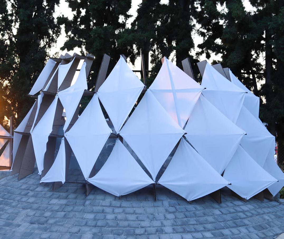
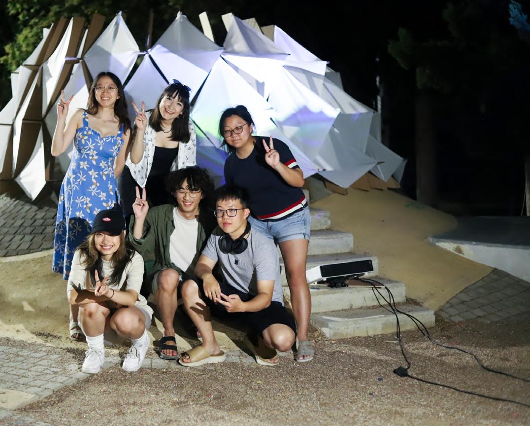
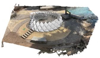
The Dragon Island - Playground installation for kindergarten kids in Athens
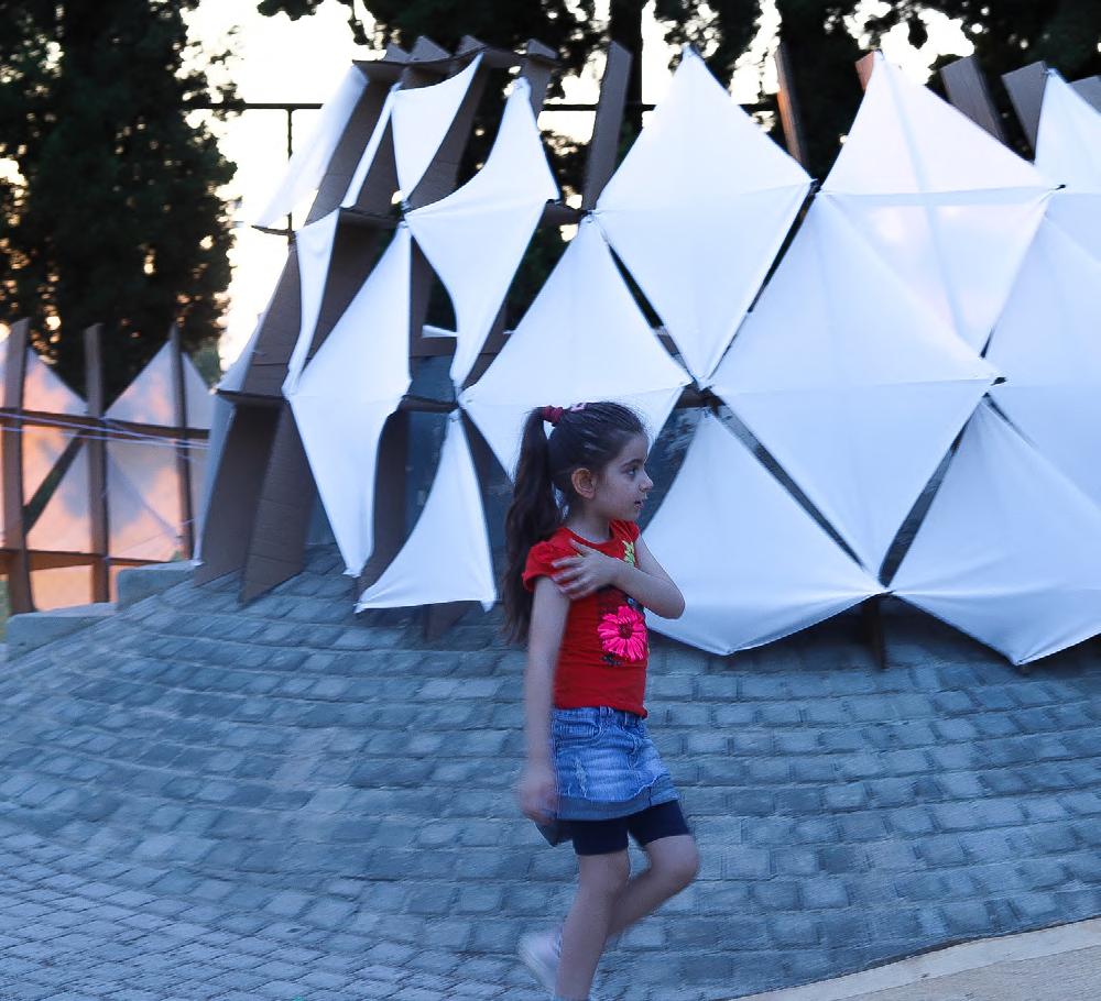
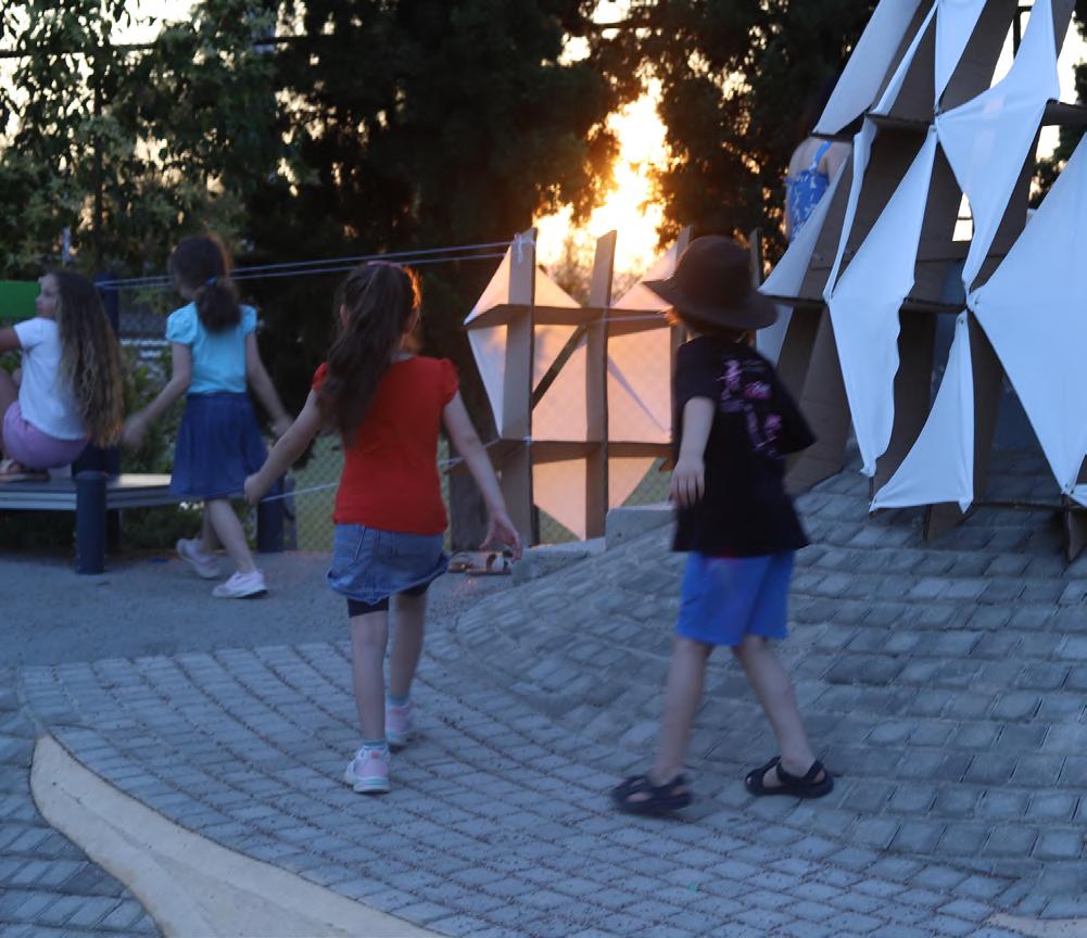
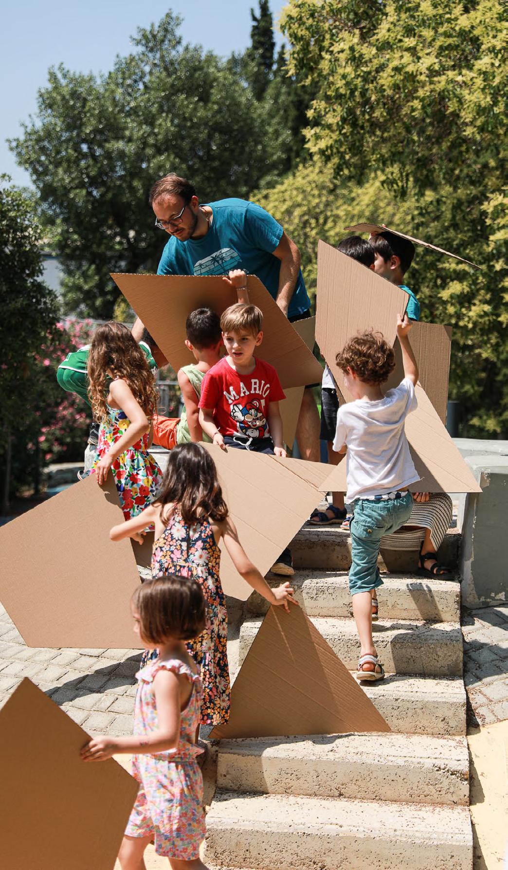
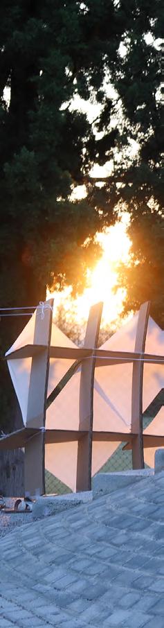
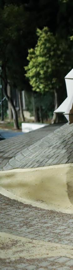
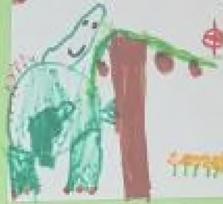

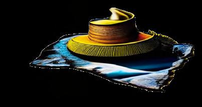
Kids' drawing + AI Reinterpretation
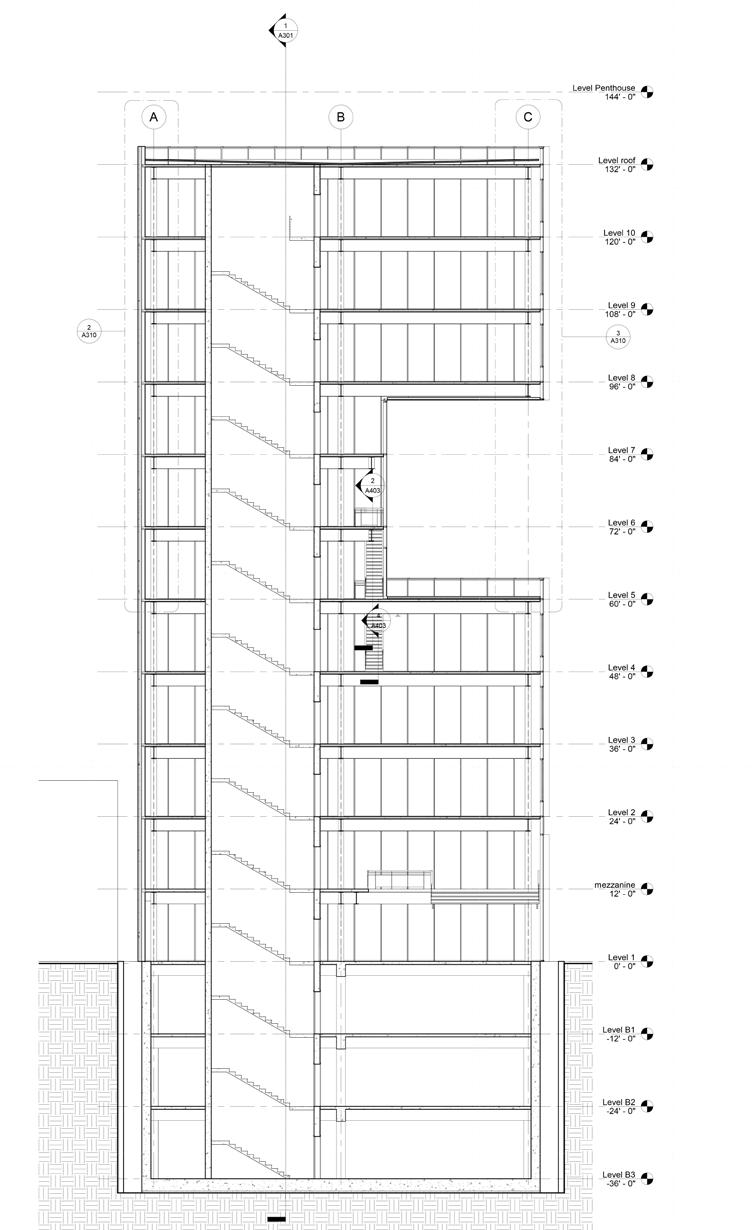
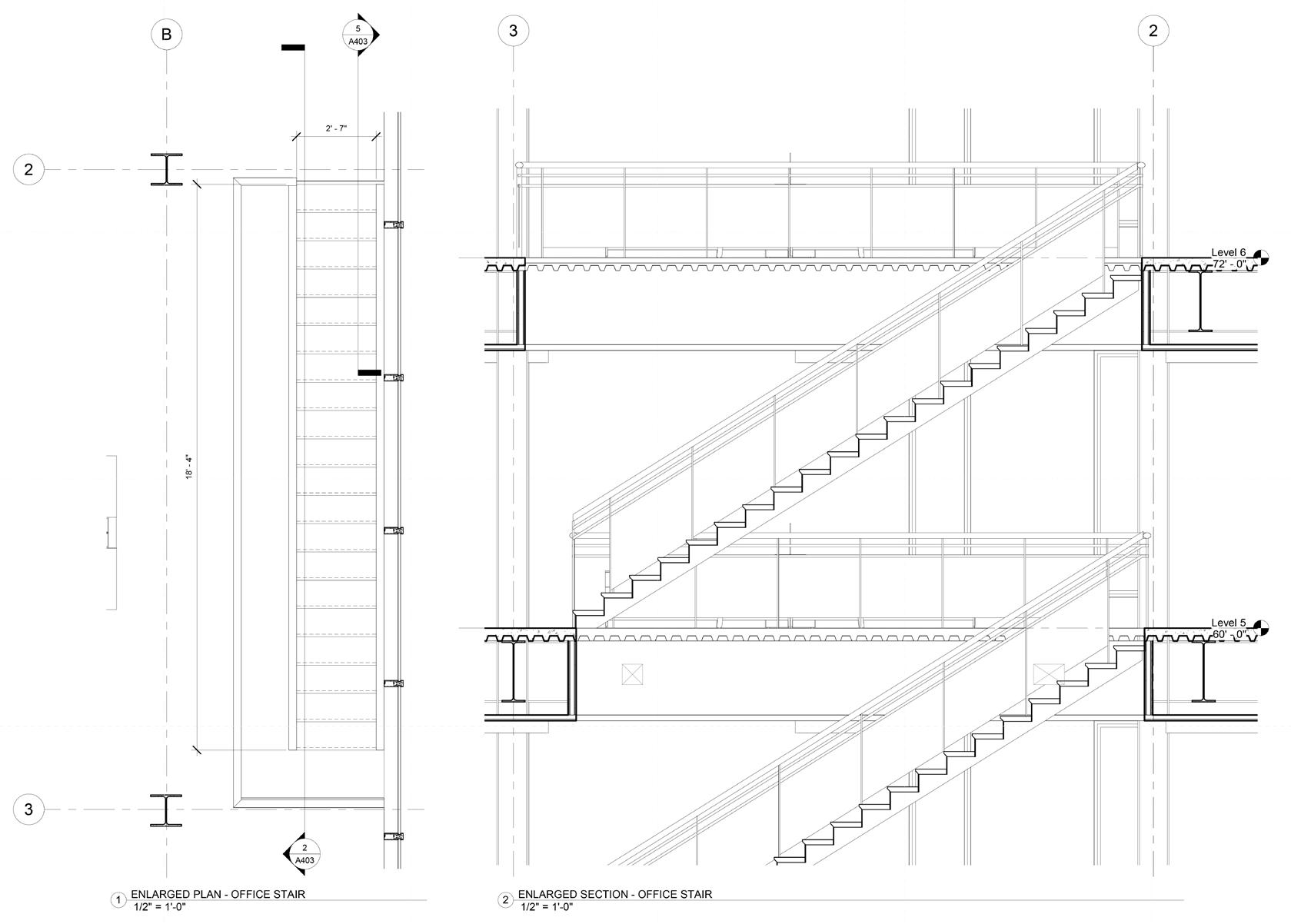
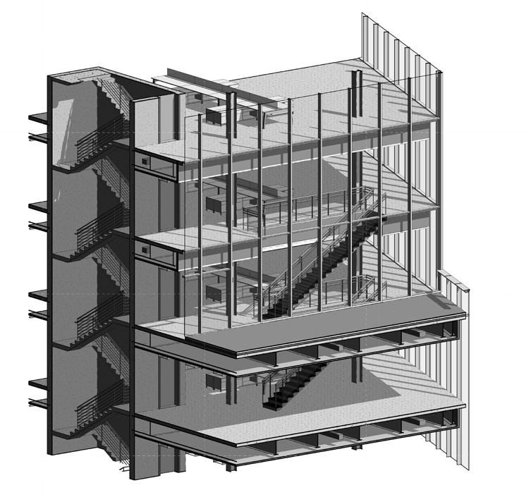
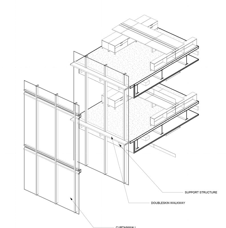
Revit practices of foundation, structural core and frame, fire egress, envelope details
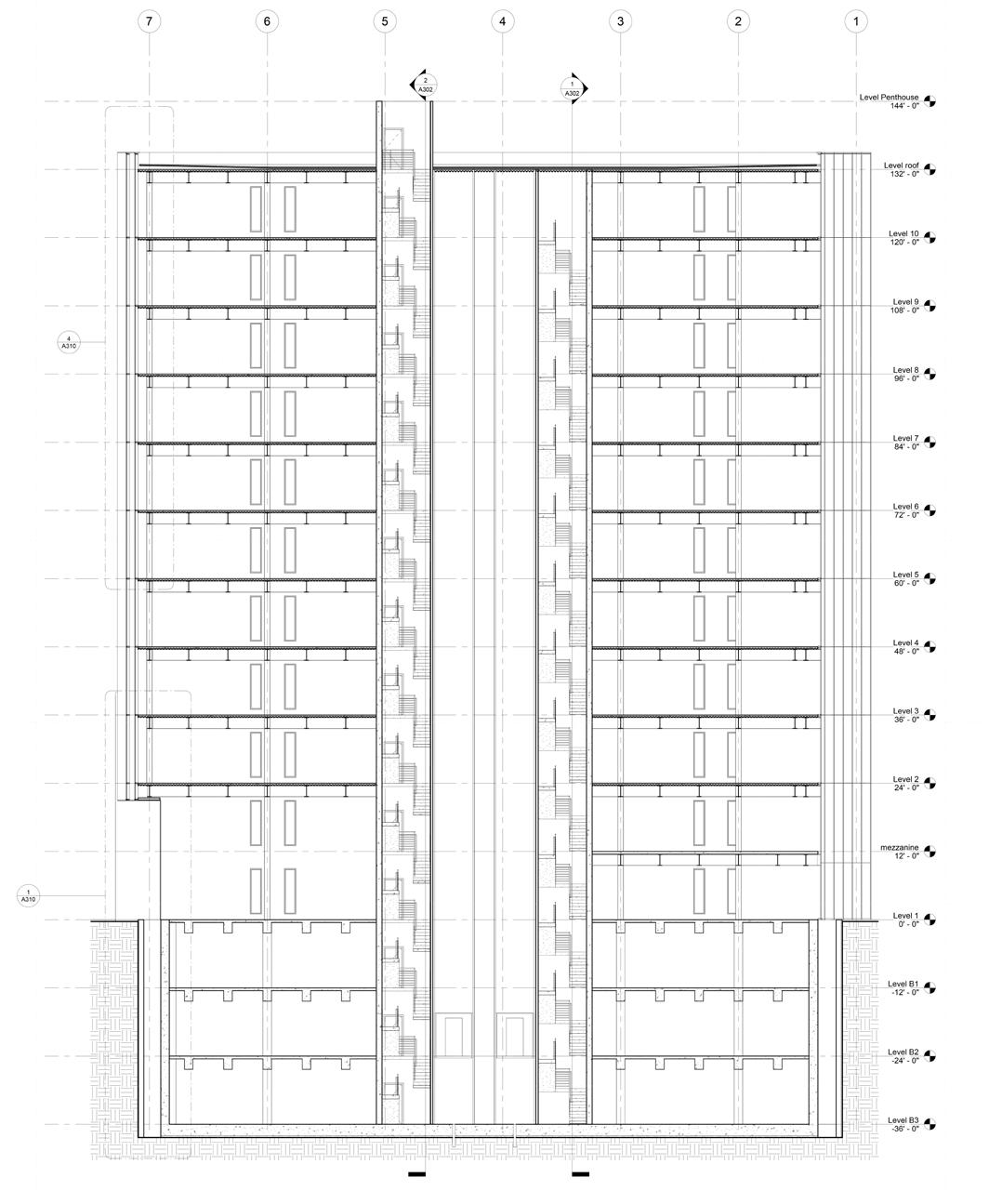
Sections
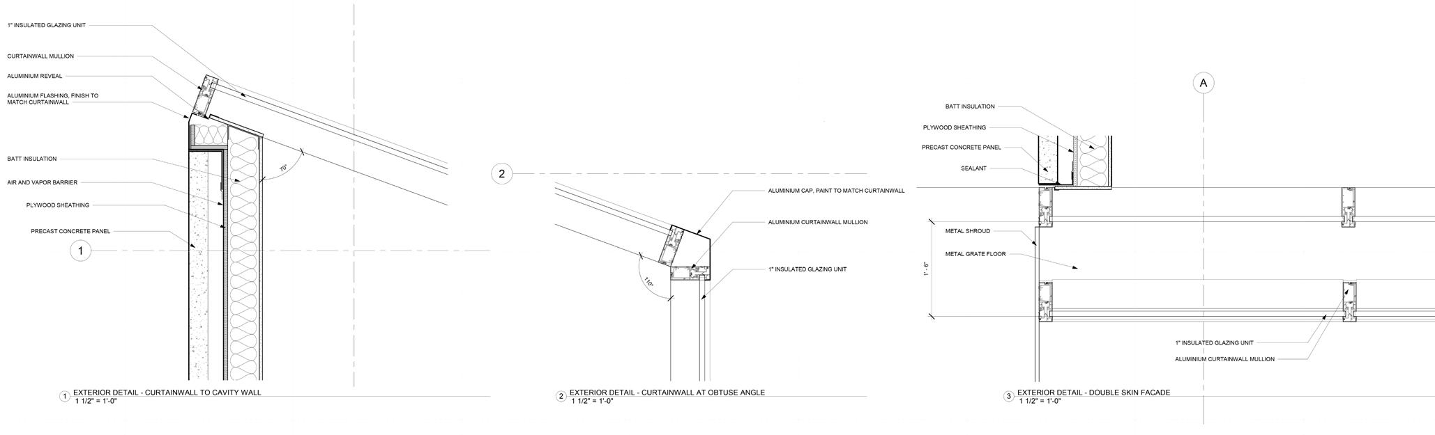
Envelop Corner Details

Thank you for your time