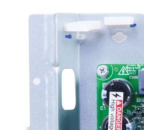
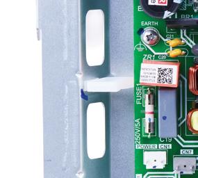
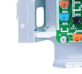
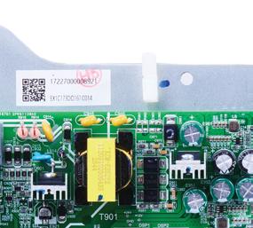
Technical Instructions
Accessory Installation
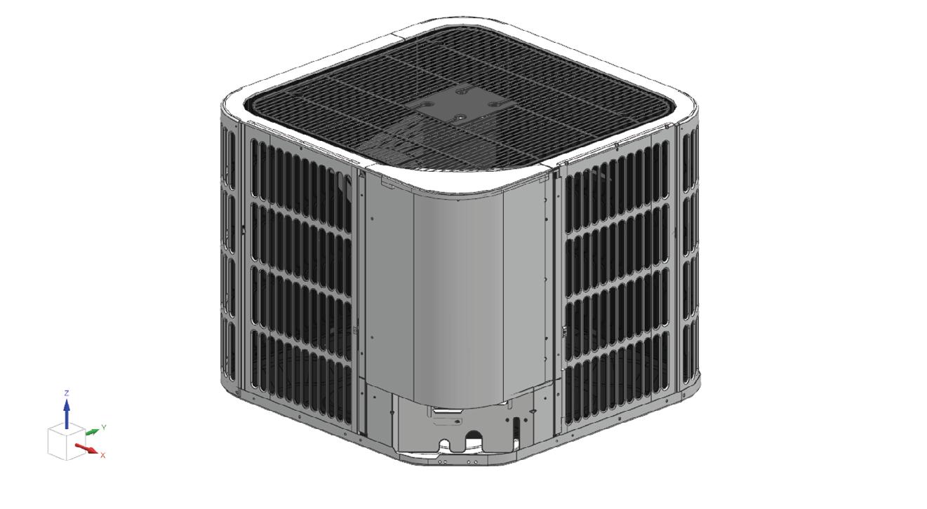
Ducted Heat Pump Gateway
1 Key to Symbols and Safety Instructions
1.1 Key to Symbols
Warnings
In warnings, signal words at the beginning of a warning are used to indicate the type and seriousness of the ensuing risk if measures for minimizing danger are not taken. The following keywords are defined and can be used in this document:
DANGER
DANGER indicates a hazardous situation which, if not avoided, will result in death or serious injury.
WARNING
WARNING indicates a hazardous situation which, if not avoided, could result in death or serious injury.
CAUTION
CAUTION indicates a hazardous situation which, if not avoided, could result in minor to moderate injury.
NOTICE
NOTICE is used to address practices not related to personal injury.
Important information
The info symbol indicates important information where there is no risk to people or property.
2 Outdoor Unit Model Numbers
The instructions in this manual are for the following models only: Bosch
8733982692
8733982286 BOHA-24RTB-M18S IDS Edge 2 ton ODU
8733982287 BOHA-36RTB-M18S IDS Edge 3 ton ODU
8733982288
BOHA-60RTB-M18S IDS Edge 5 ton ODU
8733982283 BOHA-24MTB-M18S IDS Edge 2 ton Max ODU
8733982284 BOHA-36MTB-M18S IDS Edge 3 ton Max ODU
8733982285 BOHA-60MTB-M18S IDS Edge 5 ton Max ODU
Table 1 Bosch ODU Models & Part Numbers
Coleman, Champion, Fraser-Johnston, Luxaire
Number
XD524E2D11
SPLT HP 15SEER2 2.0T R454B PUR
XD536E2D11 RES SPLT HP 15SEER2 3.0T R454B PUR
XD560E2D11 RES SPLT HP 15SEER2 5.0T R454B PUR
PH9E36N00D21 RESPK HP/E PH9 19 SEER2 3T R454B
PH9E60N00D21 RESPK HP/E PH9 19 SEER2 5T R454B
Table 2 Coleman, Champion, Fraser-Johnston, Luxaire ODU Models & Part Numbers
York
YD524E2D11 RES SPLT HP 15SEER2 2.0T R454B PUR
YD536E2D11 RES SPLT HP 15SEER2 3.0T R454B PUR
YD560E2D11 RES SPLT HP 15SEER2 5.0T R454B PUR
PH9E36N00D21 RESPK HP/E PH9 19 SEER2 3T R454B
PH9E60N00D21 RESPK HP/E PH9 19 SEER2 5T R454B
Table 3 York ODU Models & Part Numbers
4
Accessory Installation Instructions for IDS Light and YD5-XD5 Outdoor Units
1. Turn off power to the unit and wait at least 3 minutes.
WARNING
Hazardous voltage 380 volts DC!
Wait 3 minutes after disconnecting power, then verify DC voltage is less than 43 VDC at inverter test points P-N.
Components may store a dangerous electrical potential of 380 Volts DC. Failure to follow these instructions could result in personal injury or death.
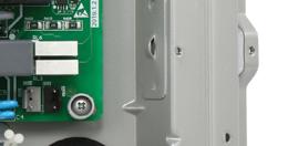
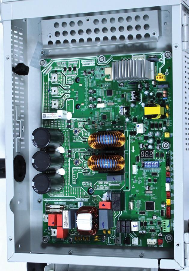
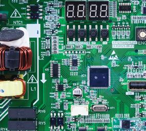
2. Remove the access panel to the control board (Figure 2). Keep Screws for re-use.
NOTICE
Product damage!
Do not directly touch the components on the main board to avoid static electricity damage.
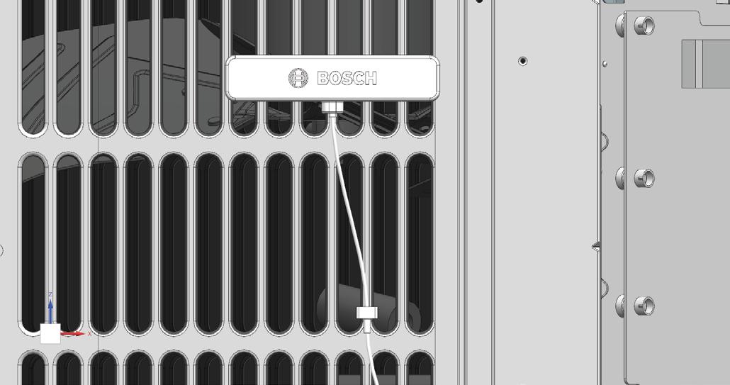
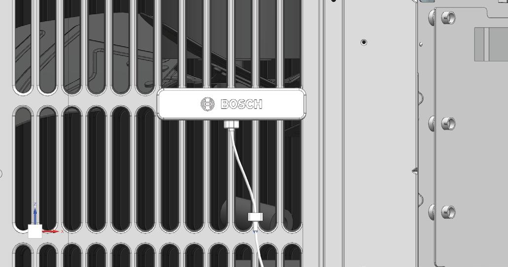
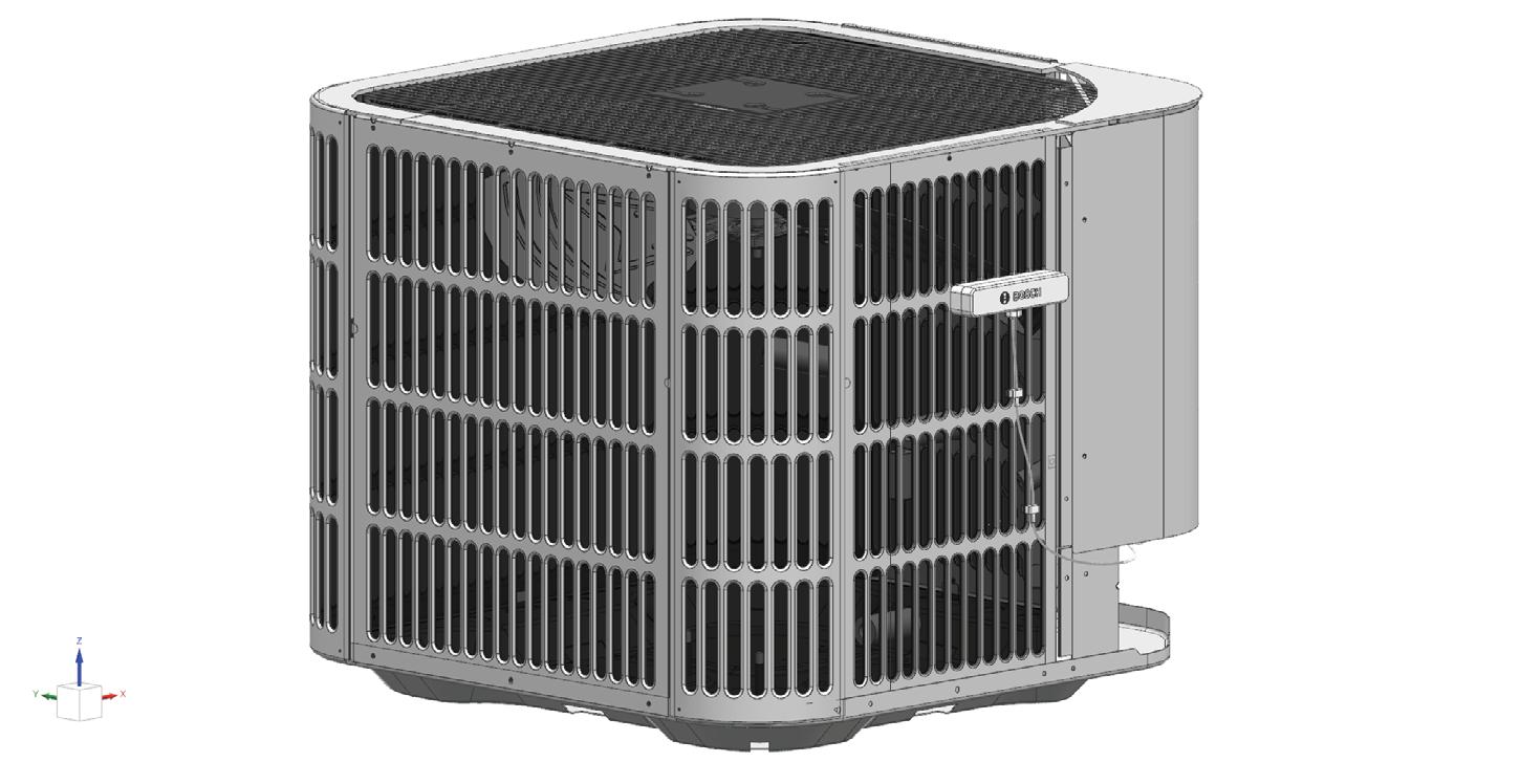
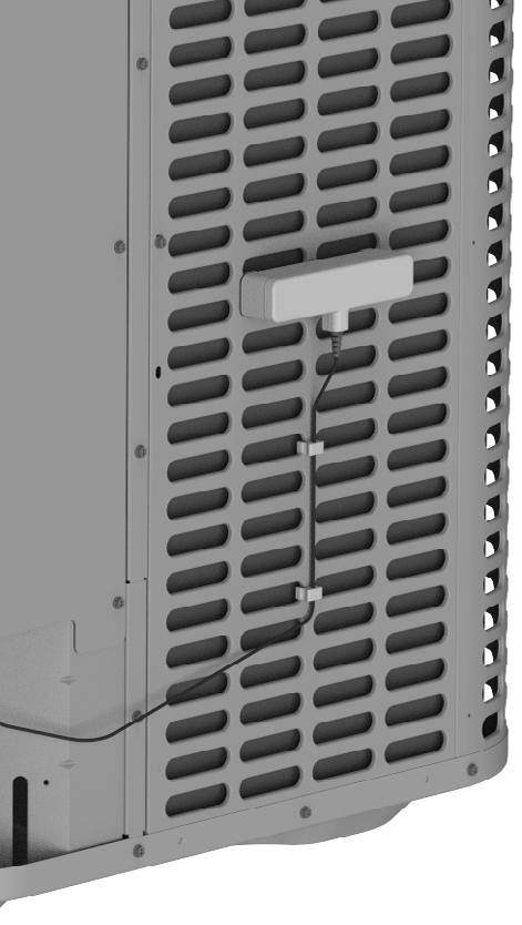
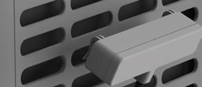
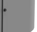
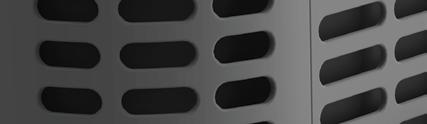
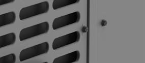
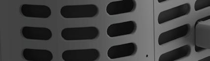
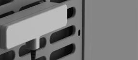
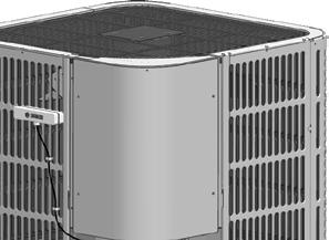
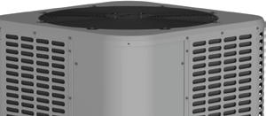
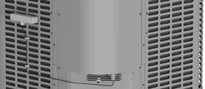
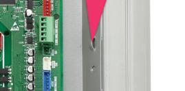
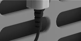
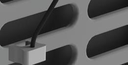
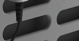
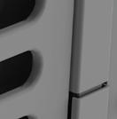
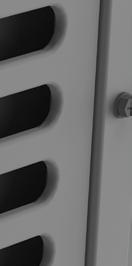
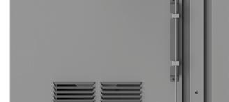
3. For IDS Light, Center and install new antenna on the 3rd louver by lining up the antenna with the grills in parallel and pushing down on the top of the antenna (Refer to Figure 3 and Figure 4). For YD5-XD5, center and install new antenna 1.5 ft above ground by lining up
Figure 2 Control Board Access
Louvers
Figure 3
PUSH DOWN ON TOP CORNERS
Figure 4
1.5 ft
Figure 5
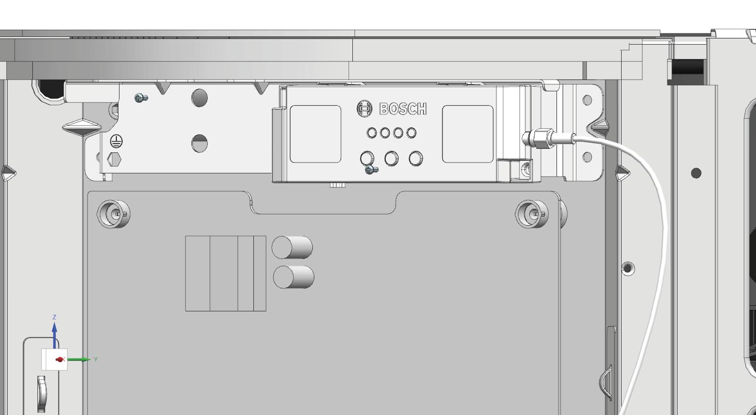
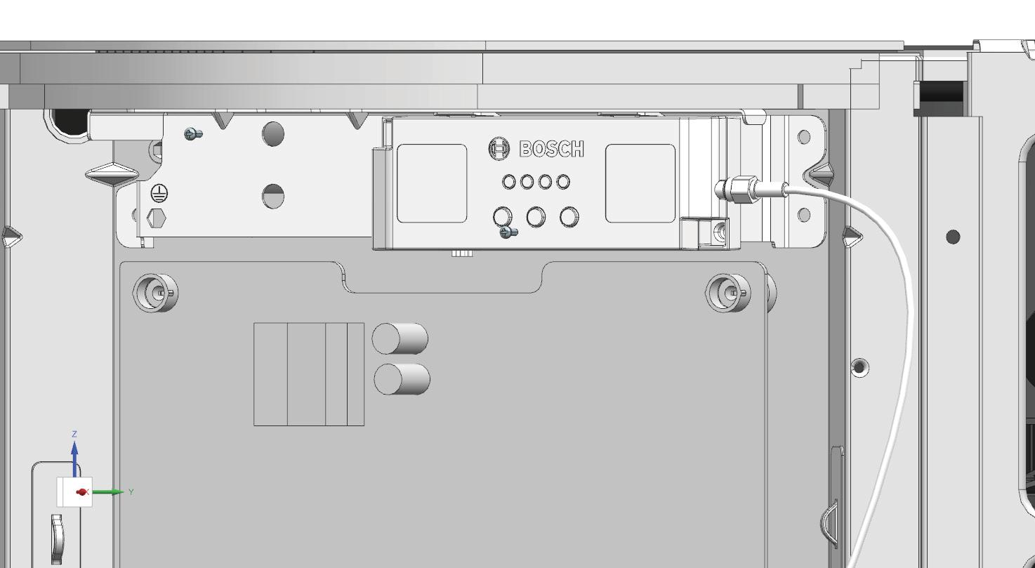
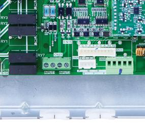
5. Install the new Gateway on the unit using 2 machine screws (Refer to Figure 9).
Plug
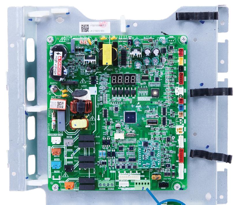
the cable connecting the gateway to the control board fully into the green connector (Refer to Figure 10).
4. Ensure the antenna on the left or right side of the unit depending on which is furthest from a wall. (Refer to Figure 7 and Figure 8).
Figure 6
Mount antenna away from wall
Figure 7
Mount antenna away from wall
Figure 8
Figure 9
6.
in
Figure 10 Gateway Connection Location for IDS Light and YD5-XD5
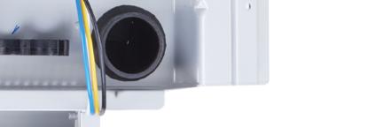
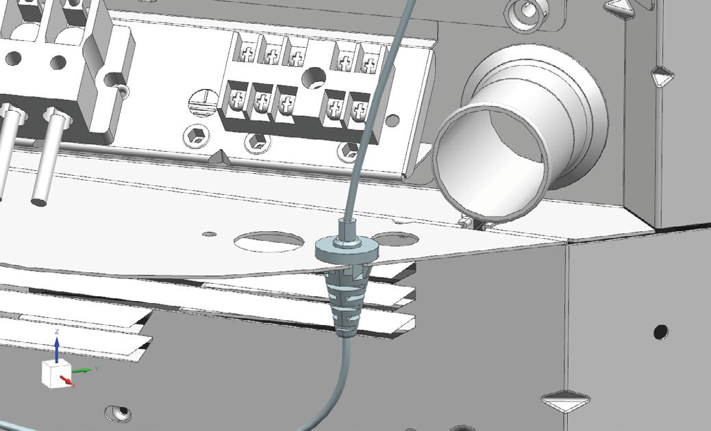
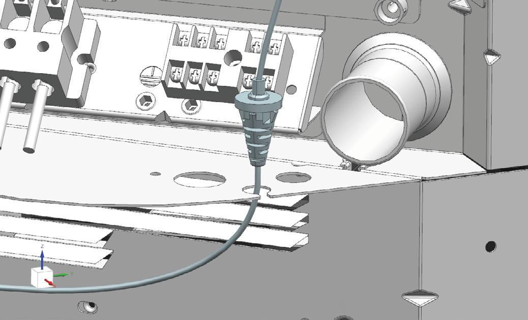
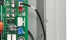
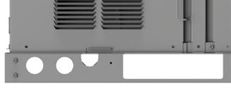
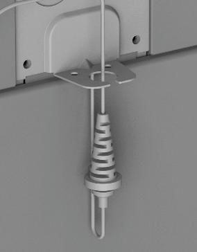
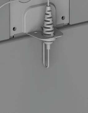
7. Run the antenna cable through the middle hole as shown below and push down on the cable strainer until it snaps into place (Refer to Figure 11).
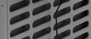
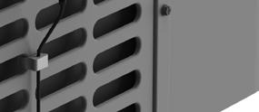
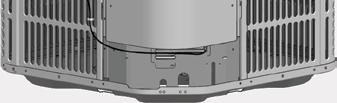
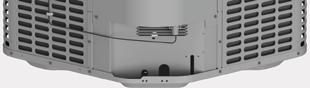
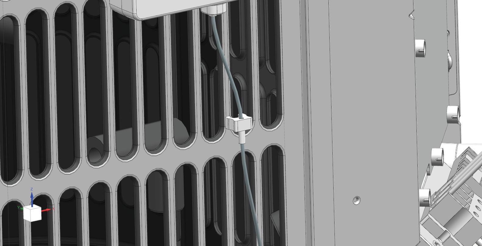
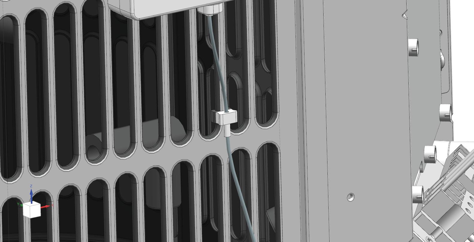
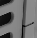
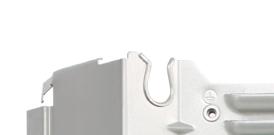
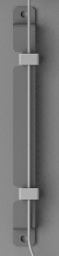
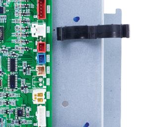
9. Attach the two antenna cable clips to the vertical louvers to secure the cable to the unit (Refer to Figure 13 and Figure 14).
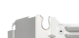
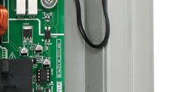
8. Bundle the wires on the right of the control board by feeding the zip-ties through the three loops on the E-box and cut off the excess zip-tie ends (Refer to Figure 12).
Figure 11
Figure 12
Figure 13 SECURED PUSH TO SECURE
Figure 14
10. Double check all wire connections, grounding, and screw positions before powering the unit ON.
11. Power ON the unit and have the homeowner set up their heat pump using the Bosch EasyAir or GoTemp Home app, depending on their appliance model.
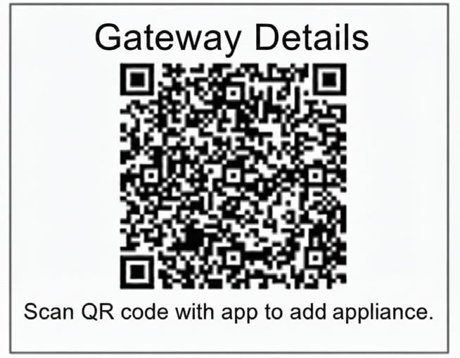
The homeowner needs the "Gateway Details" sticker (Figure 15) to onboard their heat pump. Before completing the installation, ensure you do one of the following:
• Hand the 'Gateway Details' sticker directly to the homeowner.
• Affix the sticker on the appliance's rating panel, ensuring it is clearly visible.
Gateway Details
Scan QR code with app to add appliance.
Figure 15
5 Accessory Installation Instructions for IDP Premium and PH9 Packaged Units
1. Turn off power to the unit and wait at least 3 minutes.
WARNING
Hazardous voltage 380 volts DC!
Wait 3 minutes after disconnecting power, then verify DC voltage is less than 43 VDC at inverter test points P-N.
Components may store a dangerous electrical potential of 380 Volts DC. Failure to follow these instructions could result in personal injury or death.
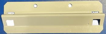
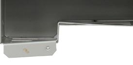
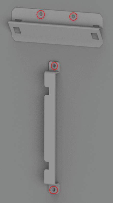
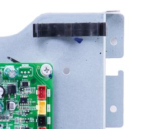
2. On the lower left corner panel, install the antenna mounting bracket using the sheet metal screws by aligning the guide holes on the panel with the screw holes on the bracket (refer to Figure 16).
3. Install the antenna cable clip bracket using the sheet metal screws by aligning the guide holes on the panel with the screw holes on the bracket (refer to Figure 16).
6. Plug in the cable connecting the gateway to the control board fully into the green connector (Refer to Figure 20).
Remove the lower left corner panel and the control board access panel (Figure 17 and Figure 18). Keep Screws for re-use.
NOTICE
Product damage!
Only use the supplied sheet metal screws and ensure the screw holes are aligned to avoid damaging internal components.
NOTICE
Product damage!
Do not directly touch the components on the main board to avoid static electricity damage.
7. Run the antenna cable through the middle hole as shown below and push down on the cable strainer until it snaps into place (Refer to Figure 21).
Figure 16
Figure 17
4.
Figure 18
5. Install the new Gateway on the unit using 2 machine screws (Refer to Figure
Figure 19
Figure 20 Gateway Connection Location for IDP Premium and PH9
8. Bundle the wires on the right of the control board by feeding the zip-ties through the three loops on the E-box and cut off the excess zip-tie ends (Refer to Figure 22).
9. Route the antenna cable through the cable hole on the lower right corner of the E-Box Access Panel (refer to Figure 23).
10. Install the antenna on the antenna mounting bracket by pushing down on the antenna.
11. Attach the two antenna cable clips to the antenna mounting bracket to secure the cable to the unit (Refer to Figure 24).
Ensure there is no excess tension on the cable.
12. Double check all wire connections, grounding, and screw positions before powering the unit ON.
13. Power ON the unit and have the homeowner set up their heat pump using the Bosch EasyAir or GoTemp Home app, depending on their appliance model.
The homeowner needs the 'Gateway Details' sticker (Figure 25) to on-board their heat pump. Before completing the installation, ensure you do one of the following:
• Hand the 'Gateway Details' sticker directly to the homeowner.
• Affix the sticker on the appliance's rating panel, ensuring it is clearly visible.
Figure 21
Figure 22
Figure 23
Figure 24
6 Accessory Installation Instructions for IDS Edge Outdoor Units
1. Turn off power to the unit and wait at least 3 minutes.
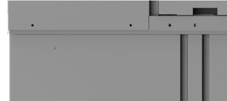
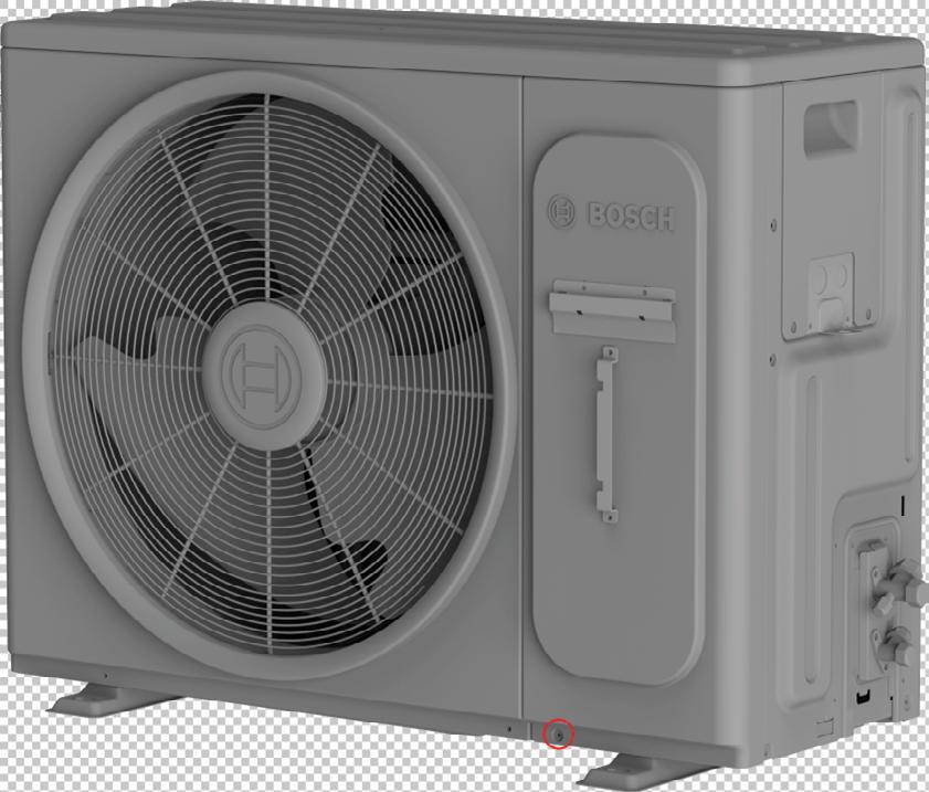
2. On the service access panel, install the antenna mounting bracket using the sheet metal screws by aligning the guide holes on the panel with the screw holes on the bracket.
WARNING
Hazardous voltage 380 volts DC!
Wait 3 minutes after disconnecting power, then verify DC voltage is less than 43 VDC at inverter test points P-N.
Components may store a dangerous electrical potential of 380 Volts DC. Failure to follow these instructions could result in personal injury or death.
3. Install the antenna cable clip bracket using the sheet metal screws by aligning the guide holes on the panel with the screw holes on the bracket (refer to Figure 26).
4. Install the antenna cable clip bracket using the sheet metal screws by aligning the guide holes on the panel with the screw holes on the bracket (refer to Figure 26).
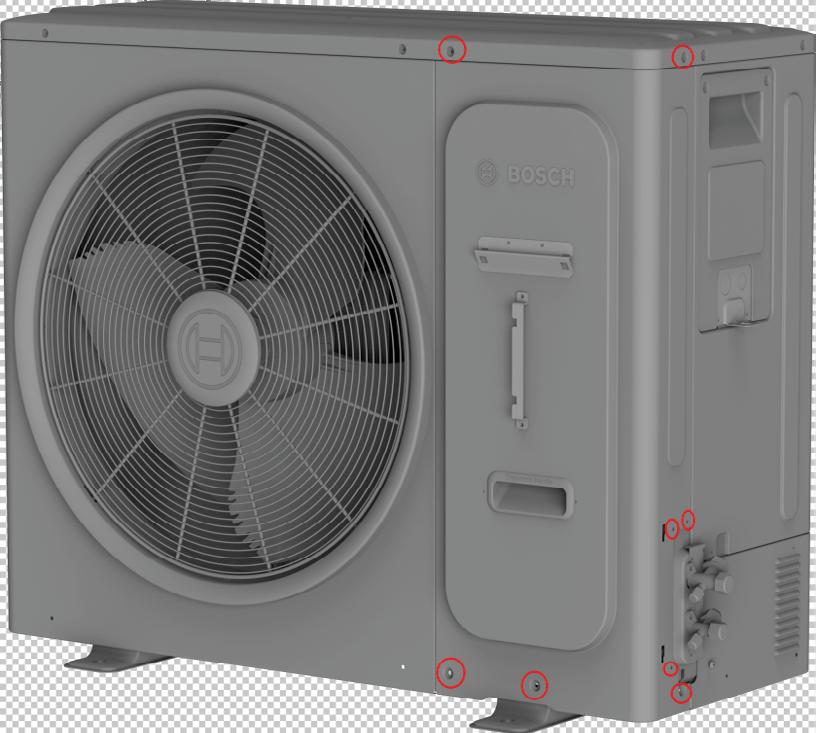
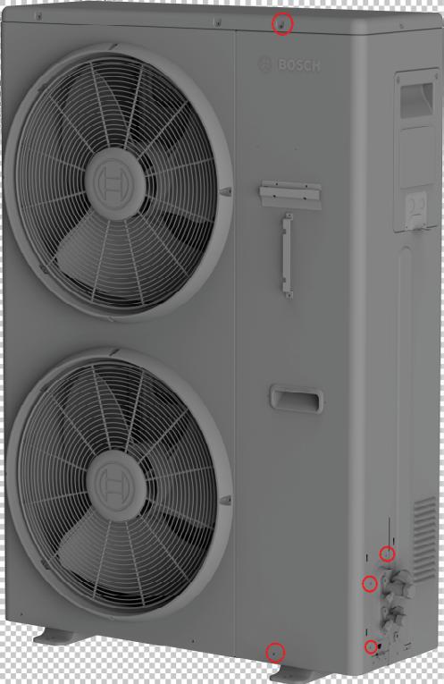
5. Remove the front right panel to access the control board (Figure 27 to Figure 29). Keep Screws for re-use.
NOTICE
Product damage!
Only use the supplied sheet metal screws and ensure the screw holes are aligned to avoid damaging internal components.
NOTICE
Product damage!
Do not directly touch the components on the main board to avoid static electricity damage.
Figure 26
Figure 27 2-Ton Cabinet Screw Location
Figure 28 3-Ton Cabinet Screw Location
Figure 29 5-Ton Cabinet Screw Location
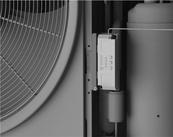
6. Install the new Gateway on the unit using 2 machine screws (Refer to Figure 30).
7. Plug in the cable connecting the gateway to the control board fully into the green connector (Refer to Figure 31).
8. Run the antenna cable through the electrical knockout on the side as shown below and push down on the cable strainer until it snaps into place (Refer to Figure 32).
9. Bundle the wires on the right of the control board with the cable organizers on the E-box (Refer to Figure 33).
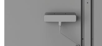
10. Install the antenna on the antenna mounting bracket by pushing down on the antenna.
11. Attach the two antenna cable clips to the cable clip bracket to secure the cable to the unit (Refer to Figure 34).
Ensure there is no excess tension on the cable.
Figure 30
Figure 31 Gateway Connection Location for IDS Edge
Figure 32
Figure 33
Figure 34
12. Double check all wire connections, grounding, and screw positions before powering the unit ON.
13. Power ON the unit and have the homeowner set up their heat pump using the Bosch EasyAir app
7 Mobile App Setup (Homeowner)
1. Depending on the brand of the Outdoor unit, Download the GoTemp Home or Bosch EasyAir on your smartphone by searching for it in Google Play Store (for Android devices) or App Store (for iPhone). Alternatively, you can scan the QR codes below with your phone’s camera:
Bosch
The homeowner needs the 'Gateway Details' sticker (Figure 36) to on-board their heat pump. Before completing the installation, ensure you do one of the following:
• Hand the 'Gateway Details' sticker directly to the homeowner.
• Affix the sticker on the appliance's rating panel, ensuring it is clearly visible
2. Once the app is downloaded, register with SingleKey ID & create a profile to access your account.
3. If utilizing Bosch EasyAir App, Select "Homeonwer" role when prompted to add your Ducted Heat Pump to the app. Alternatively, If utilizing GoTemp Home app, select the brand of the outdoor unit prior to selecting the Ducted Heat pump you want want to add to the mobile app.
4. Follow the on-screen steps for entering the outdoor serial number and gateway information to successfully onboard your Ducted Heat-pump and the Gateway Accessory.
Figure 35
Figure 37
York, Coleman, Champion, Fraser -Johnston, Guardian, Evcon, Luxaire
Figure 38
1. To connect to unit using Bluetooth, Download the GoTemp Pro App on your smartphone by searching for it in Google Play Store (for Android devices) or App Store (for iPhone). Alternately, you can scan the QR code below with your phone's camera.
York, Coleman, Champion, Fraser-Johnston, Luxaire
8 Mobile App Setup (Contractor)
Scan QR Code
Figure 39
BHC Group Heating & Cooling
BTC 762002308 A / 04.2026
BHC Group Heating & Cooling reserves the right tomake changes without notice due to continuing engineering and technological advances.