Ducted and Packaged Heat Pump
1 Key to Symbols and Safety Instructions
1.1 Key to Symbols
Warnings
In warnings, signal words at the beginning of a warning are used to indicate the type and seriousness of the ensuing risk if measures for minimizing danger are not taken. The following keywords are defined and can be used in this document:
DANGER
DANGER indicates a hazardous situation which, if not avoided, will result in death or serious injury.
WARNING
WARNING indicates a hazardous situation which, if not avoided, could result in death or serious injury.
CAUTION
CAUTION indicates a hazardous situation which, if not avoided, could result in minor to moderate injury.
NOTICE
NOTICE is used to address practices not related to personal injury.
Important information
The info symbol indicates important information where there is no risk to people or property.
2 Outdoor Unit Model Numbers
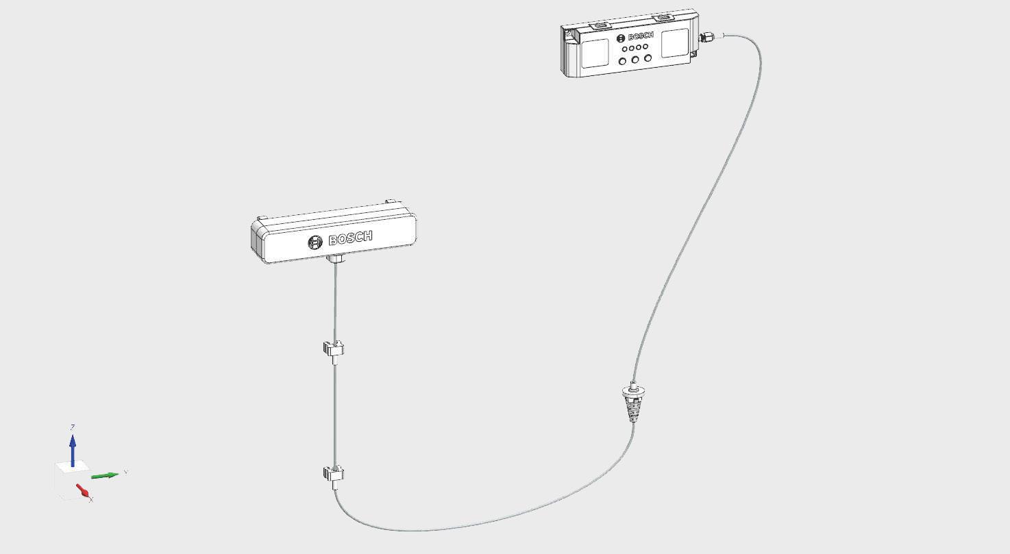
This Gateway Assembly is compatible with the following models only: Bosch
8733982679
8733982680
8733983522
8733958901
8733982676
8733982681
8733982682
8733982683
8733982692
8733982693
8733982286
8733982287
8733982288
8733982283
8733982284
8733982285
BOVB-36RTB-M20S IDS Premium Connected 3T Condenser-R454B
BOVB-60RTB-M20S IDS Premium Connected 5T Condenser-R454B
BOVB-36MTB-M19E IDS Ultra 3T Condenser
BOVA-60MTB-M19E IDS Ultra 5T Condenser
BOVB-60MTB-M19E IDS Ultra 5T Condenser
BOVB-24RTB-M15S IDS Light 2T Cond (up to 18 SEER2) R-454B
BOVB-36RTB-M15S IDS Light 3T Cond (up to 18 SEER2) R-454B
BOVB-60RTB-M15S IDS Light 5T Cond (up to 18 SEER2) R-454B
BPBB-36RTB-M18S IDP Premium 3T (18 SEER2) R-454B
BPBB-60RTB-M18S IDP Premium 5T (18 SEER2) R-454B
BOHA-24RTB-M18S IDS Edge 2 ton ODU
BOHA-36RTB-M18S IDS Edge 3 ton ODU
BOHA-60RTB-M18S IDS Edge 5 ton ODU
BOHA-24MTB-M18S IDS Edge 2 ton Max ODU
BOHA-36MTB-M18S IDS Edge 3 ton Max ODU
BOHA-60MTB-M18S IDS Edge 5 ton Max ODU
Table 1 Bosch ODU Model & Part Numbers
York
Model Number Description
YDV36E2D11 RES SPLT HP 20SEER2 3.0T R454B PUR
YDV60E2D11 RES SPLT HP 20SEER2 5.0T R454B PUR
YDC36E2D11 RES SPLT HP 19SEER2 3.0T R454B PUR
YDC60E2D11 RES SPLT HP 19SEER2 5.0T R454B PUR
YD524E2D11 RES SPLT HP 15SEER2 2.0T R454B PUR
YD536E2D11 RES SPLT HP 15SEER2 3.0T R454B PUR
YD560E2D11 RES SPLT HP 15SEER2 5.0T R454B PUR
PH9E36N00D21 RESPK HP/E PH9 19 SEER2 3T R454B
PH9E60N00D21 RESPK HP/E PH9 19 SEER2 5T R454B
Table 2 York Model Number
Coleman, Champion, Fraser-Johnston, Luxaire Model Number Description
XDV36E2D11 RES SPLT HP 20SEER2 3.0T R454B PUR
XDV60E2D11 RES SPLT HP 20SEER2 5.0T R454B PUR
XD524E2D11 RES SPLT HP 15SEER2 2.0T R454B PUR
XD536E2D11 RES SPLT HP 15SEER2 3.0T R454B PUR
XD560E2D11 RES SPLT HP 15SEER2 5.0T R454B PUR
PH9E36N00D21 RESPK HP/E PH9 19 SEER2 3T R454B
PH9E60N00D21 RESPK HP/E PH9 19 SEER2 5T R454B
Table 3 Other Brand Model Number


4 Replacement Instructions for Ducted Split Systems (Excluding IDS Edge)
1. Turn off power to the unit and wait at least 3 minutes.
WARNING
Hazardous voltage 380 volts DC!
Wait 3 minutes after disconnecting power, then verify DC voltage is less than 43 VDC at inverter test points P-N.
Components may store a dangerous electrical potential of 380 Volts DC. Failure to follow these instructions could result in personal injury or death.
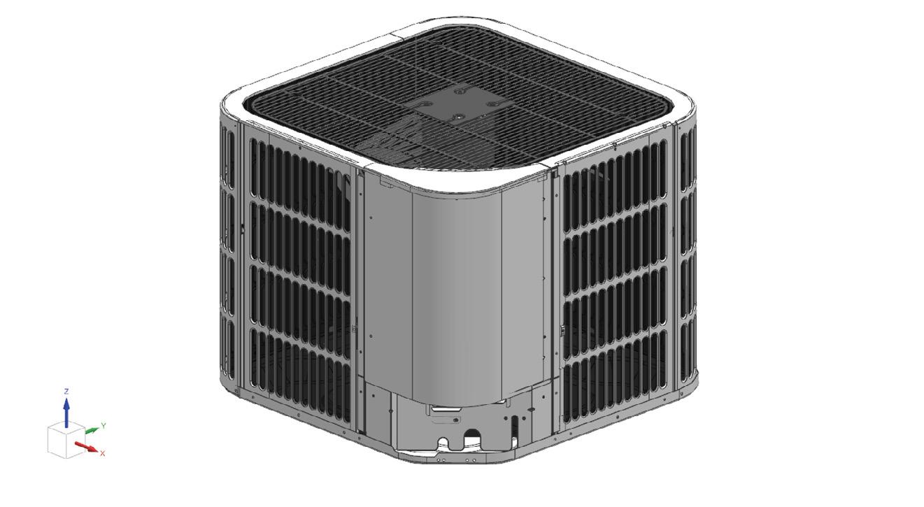
2. Remove the access panel to the control board (Figure 2). Keep Screws for re-use.
NOTICE
Product damage!
Do not directly touch the components on the main board to avoid static electricity damage.
Remove the antenna cable strainer from the bottom panel by pushing up from the bottom of the strainer (Refer to Figure 3).
For the models listed in Table 1, components 5, 6, and 7 are not used when replacing the Gateway Assembly.
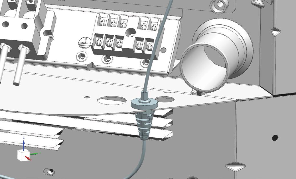
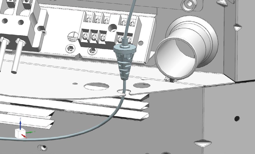
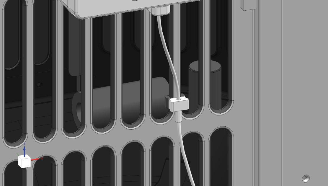
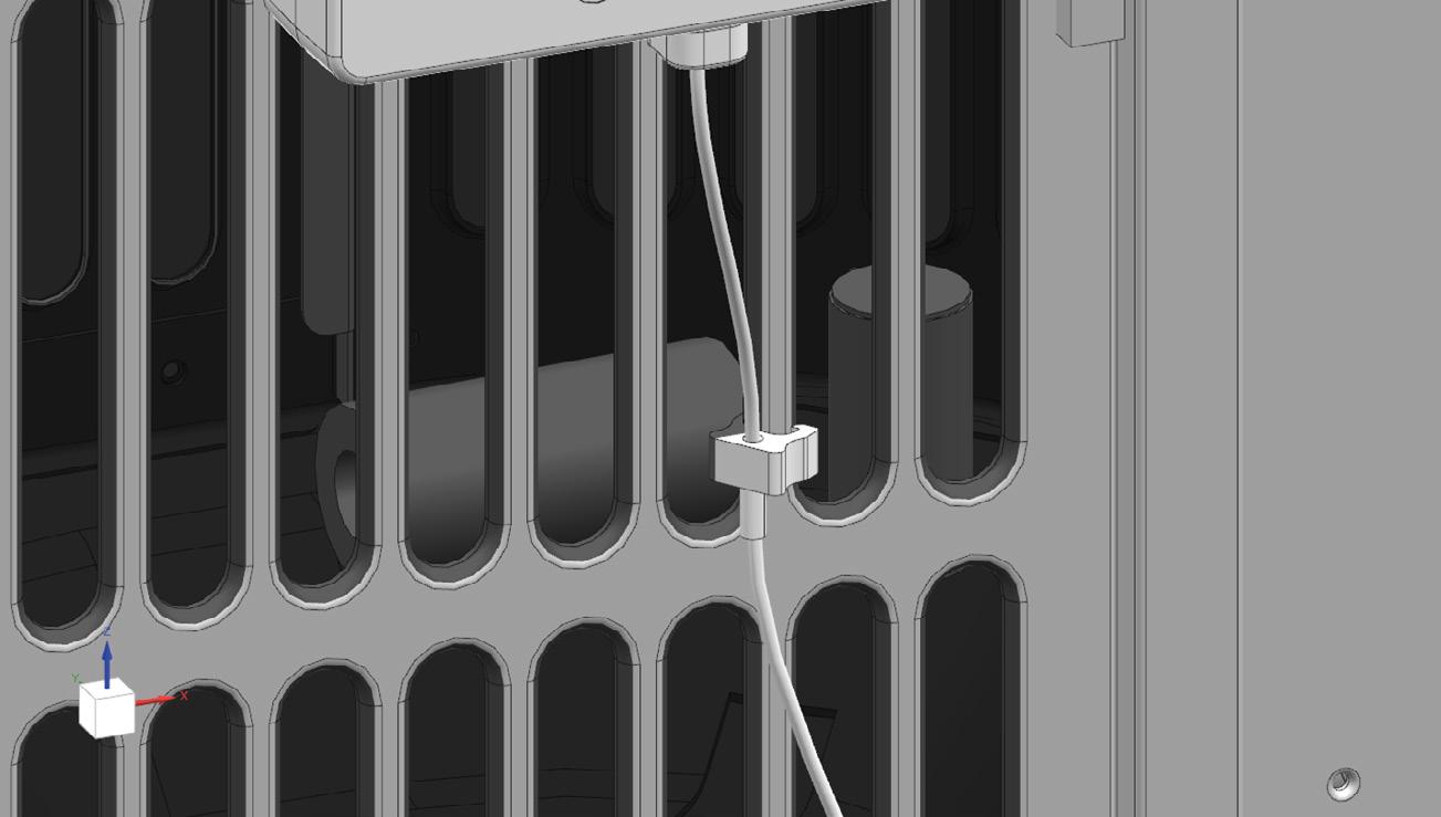
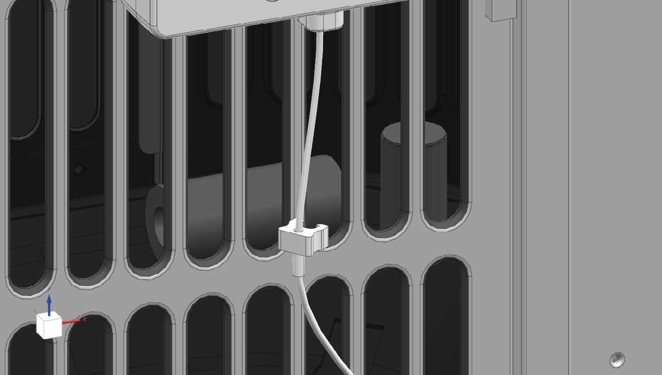
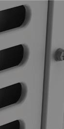
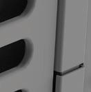
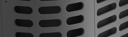
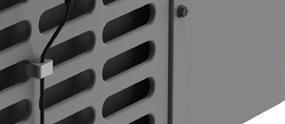
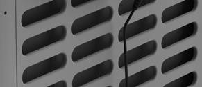
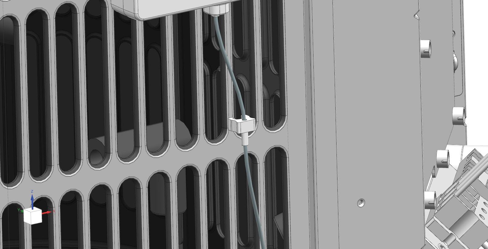
5. Remove the antenna cable clips from the louvers by rotating them about the louver (Refer to Figure 4 and Figure 5). If the clip is too tight, wiggle it and rotate the clip to remove
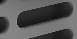

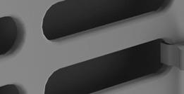
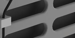
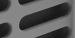
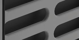
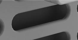
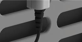

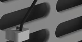
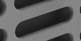
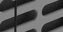

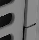
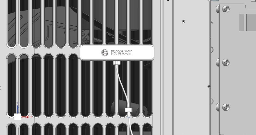
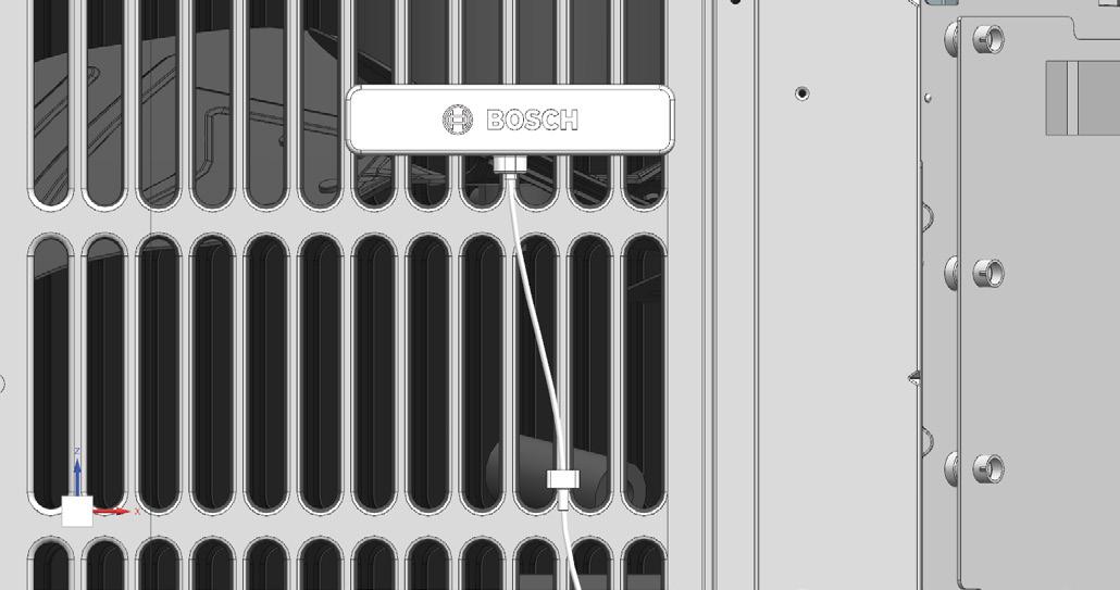
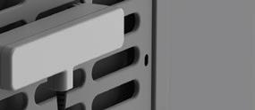
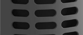
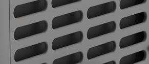
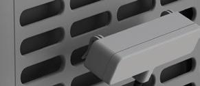
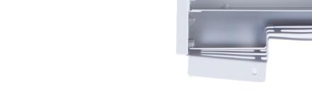
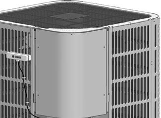
6. Remove the antenna from the louver by pushing up from the bottom corners of the antenna at the same time (Refer to Figure 6 and Figure 7).
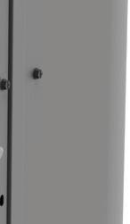
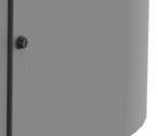
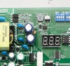
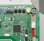
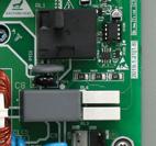
7. Unplug the cable connecting the gateway to the control board (Refer to Figure 8 and Figure 9).
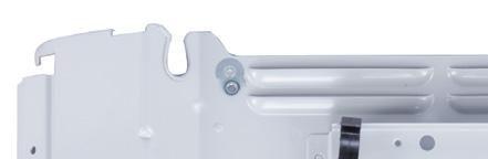
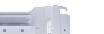
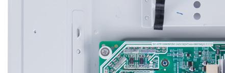
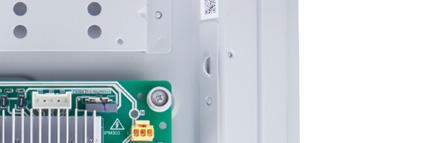
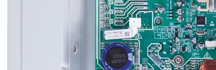
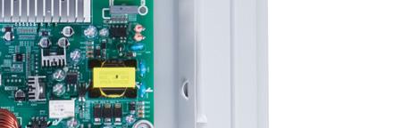
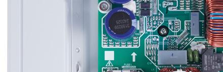
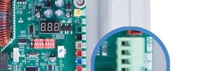
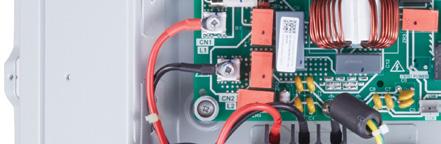
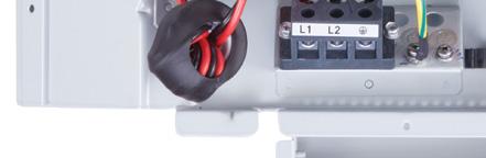
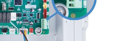
8. Uninstall the Gateway by removing the 2 screws (Refer to Figure 10).
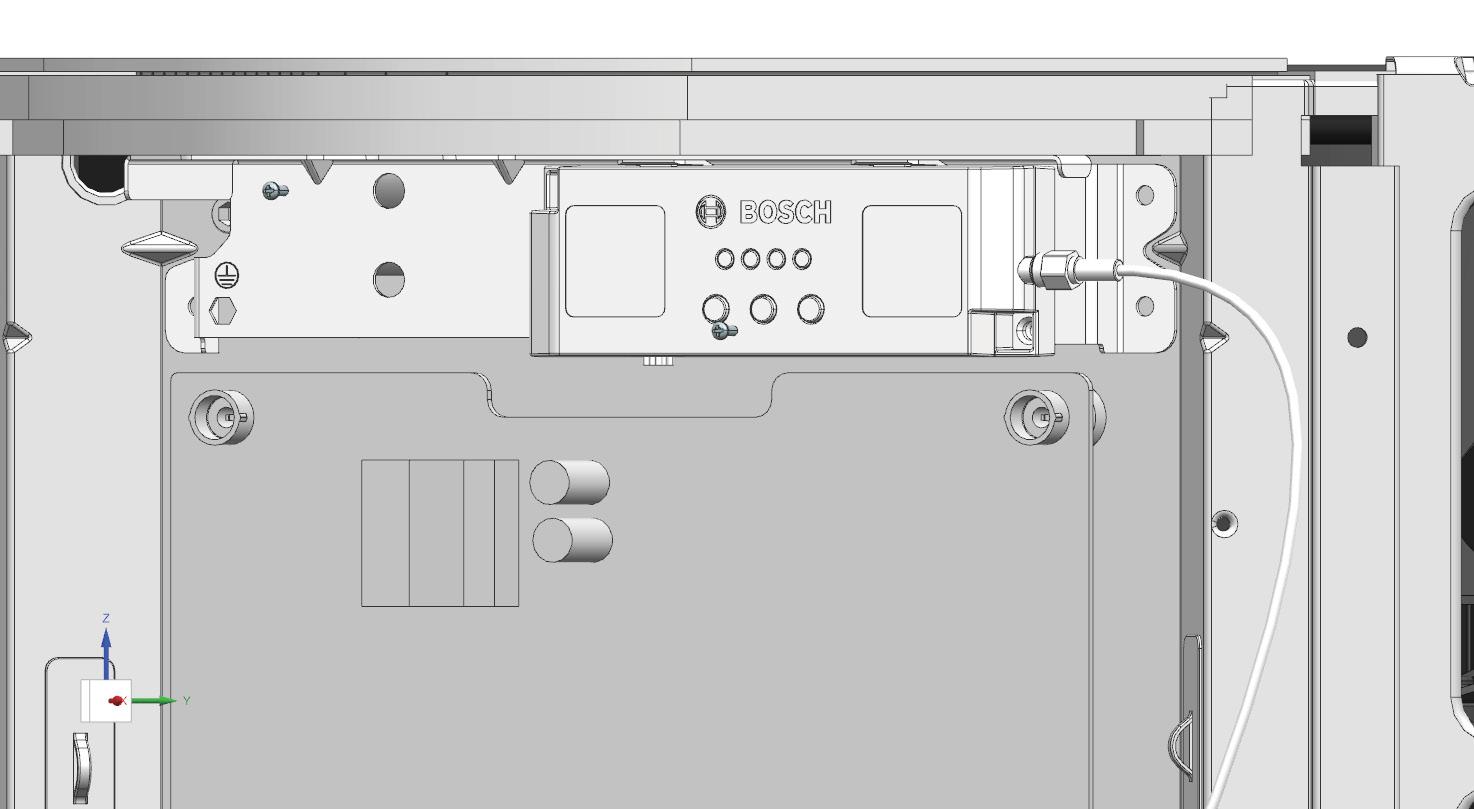
9. Old Gateway and Antenna assembly should be completely removed. Proceed to Step 10.
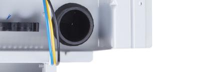
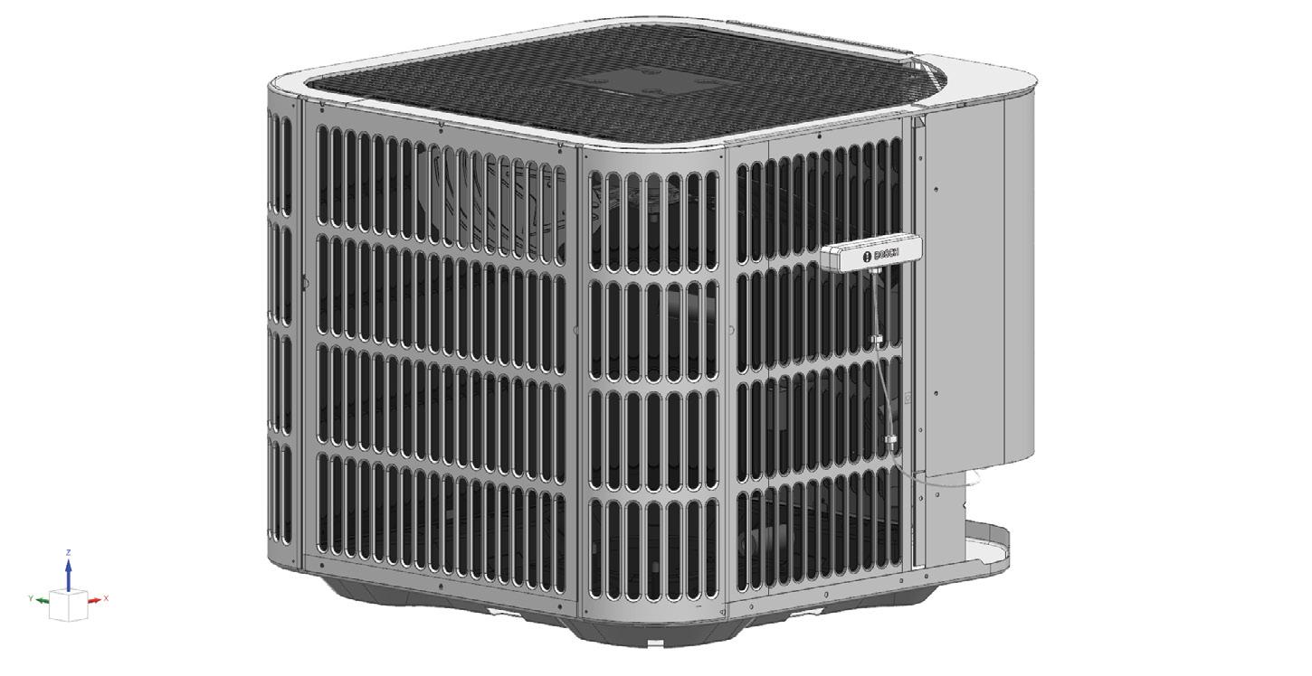
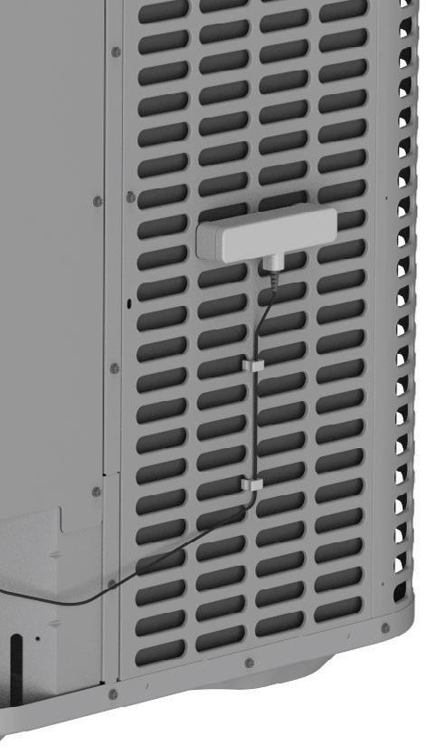
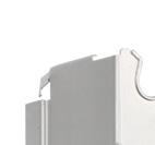
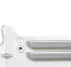
10. Center and install new antenna on the 3rd louver by lining up the antenna with the grills in parallel and pushing down on the top of the antenna (Refer to Figure 11 and Figure 12 for Bosch; refer to Figure 13 and Figure 14 for other brands).








11. Install the new Gateway on the unit using 2 screws (Refer to Figure 16).
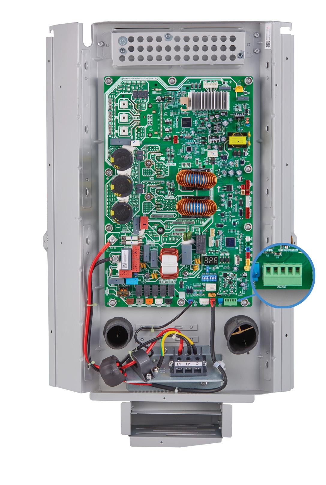
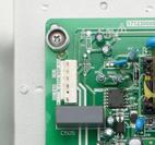
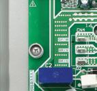
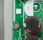
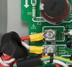
12. Plug in the cable connecting the gateway to the control board fully into the green connector (Refer to Figures on page 11).
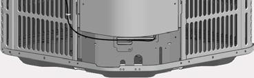
13. Run the antenna cable through the middle hole as shown below and push down on the cable strainer until it snaps into place (Refer to Figure 17
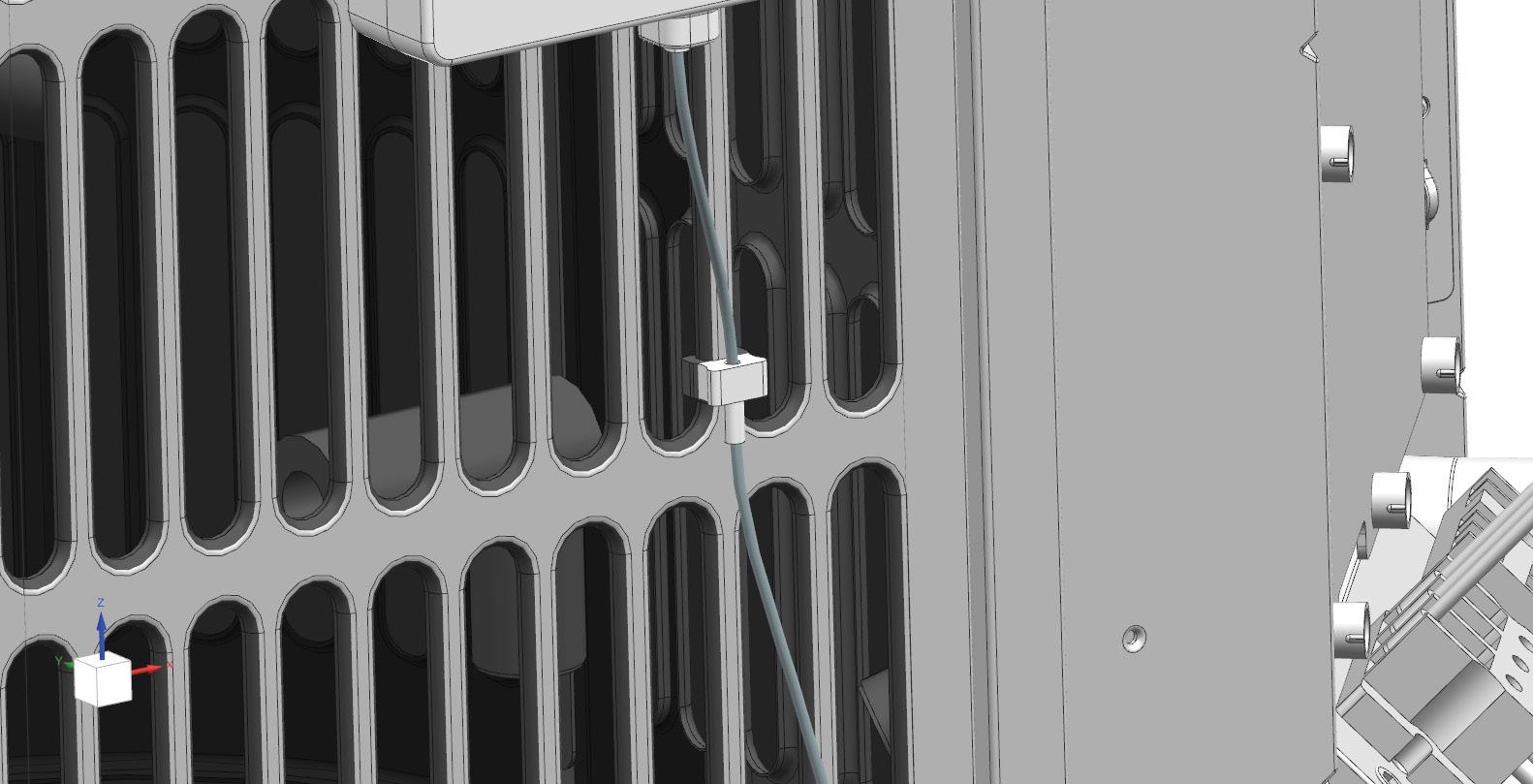
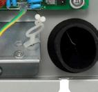
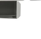
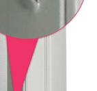
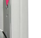
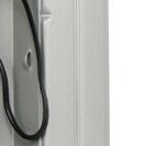
15. Attach the two antenna cable clips to the louvers to secure the cable to the unit (Refer to Figure 19 and Figure 20). SECURED PUSH TO SECURE
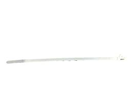
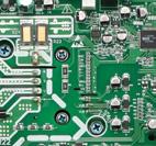
14. Bundle the wires on the right of the control board by feeding the zip-ties through the three loops on the E-box and cut off the excess zip-tie ends (Refer to Figure 18).

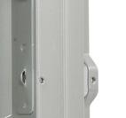
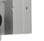

19 SECURED PUSH TO SECURE
20
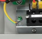
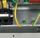
16. Double check all wire connections, grounding, and screw positions before powering the unit ON.
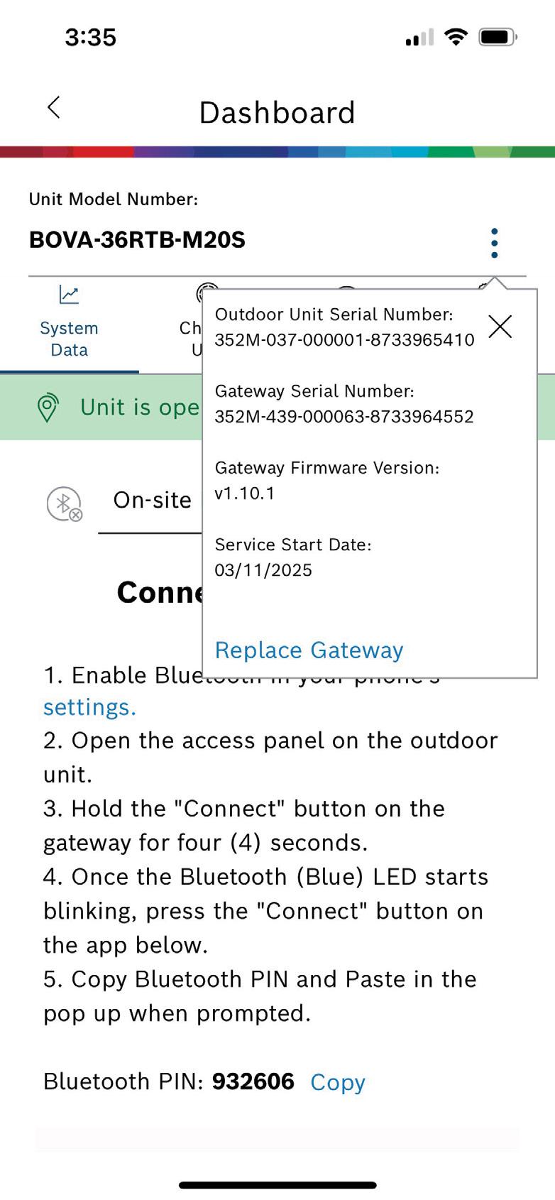
17. Power ON the unit and proceed to the mobile app to set up the Gateway.
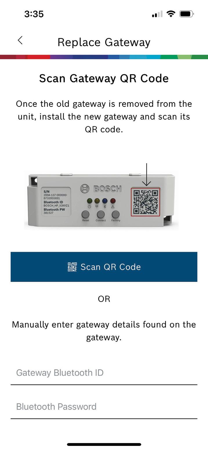
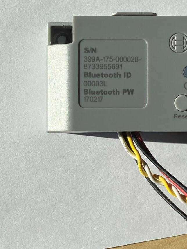
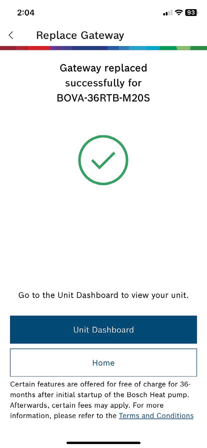
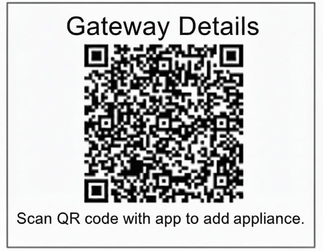
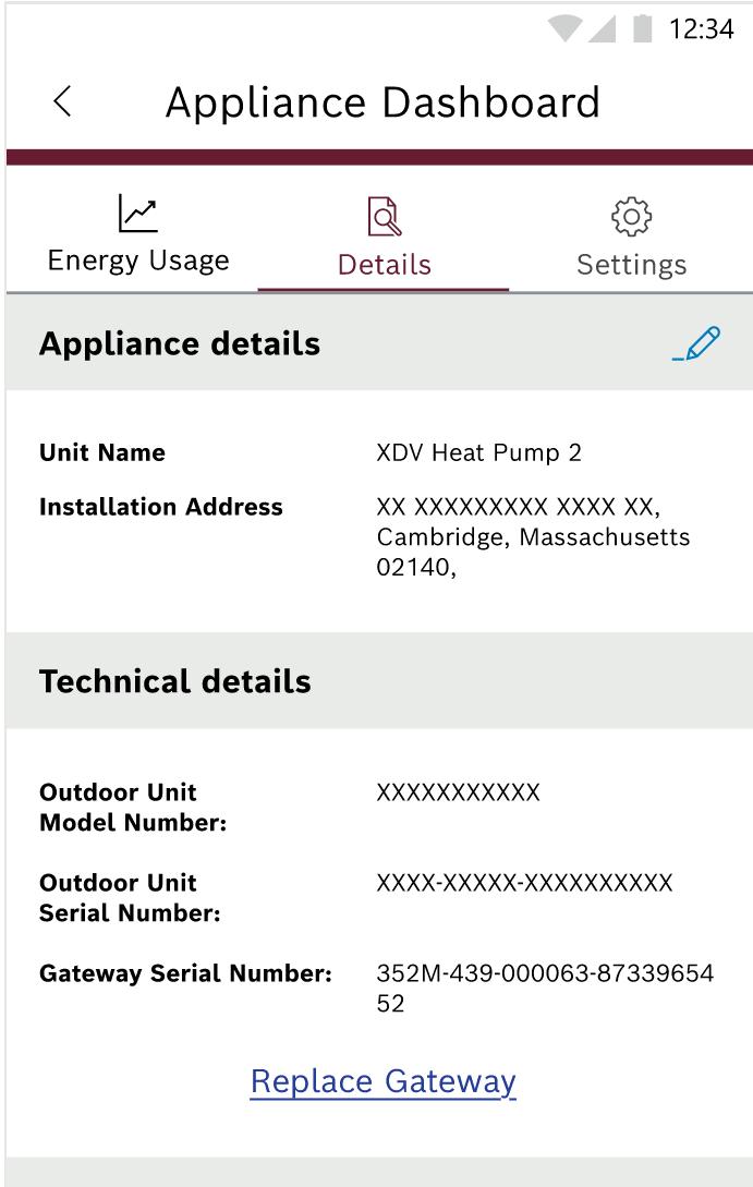
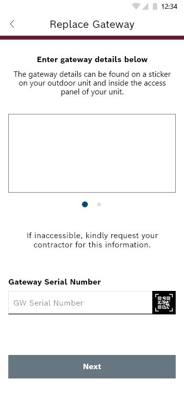
18. Refer to section 7 for new Gateway activation.
5 Replacement Instructions for Packaged Units
1. Turn off power to the unit and wait at least 3 minutes.
WARNING
Hazardous voltage 380 volts DC!
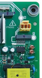
Wait 3 minutes after disconnecting power, then verify DC voltage is less than 43 VDC at inverter test points P-N.
Components may store a dangerous electrical potential of 380 Volts DC. Failure to follow these instructions could result in personal injury or death.
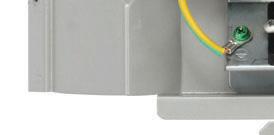
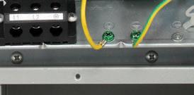
2. Double-check all wire connections, grounding, and screw positions after the power is OFF.
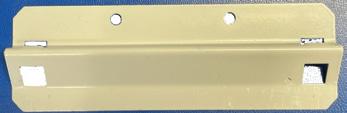
3. Remove the two antenna cable clips to the antenna mounting bracket by twisting the clips and pull to the right (Refer to Figure 21)
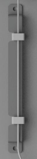
6. Cut the 3 zip-ties securing the wires on the right of the control board.
NOTICE
Product damage!
Do not directly touch the components on the main board to avoid static electricity damage.
4. Remove the antenna from the antenna mounting bracket by pushing up on the antenna.
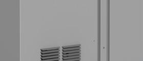
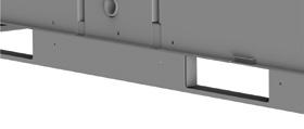
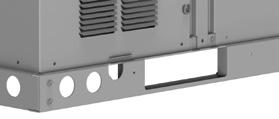
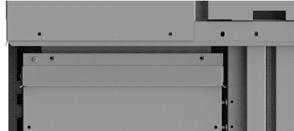
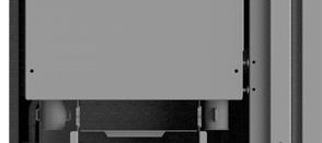
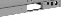
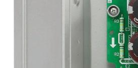
5. Remove the lower left corner panel and the control board access panel (Figure 22 and Figure 23). Keep screws for re-use.
NOTICE
Product damage!
Remove the antenna cable strainer from the bottom panel by pushing up from
Uninstall the Gateway by removing the two screws (Refer to )
9. Old Gateway and antenna assembly should be completely removed. Proceed to Step 10.
Only use the supplied sheet metal screws and ensure the screw holes are aligned to avoid damaging internal components.
10. Install the new Gateway on the unit using 2 screws (Refer to Figure 26).
Be careful not to overtighten.
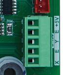
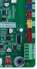
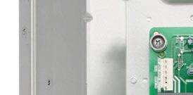
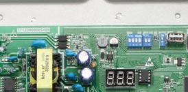
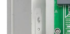
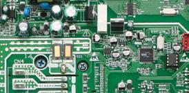
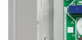
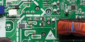
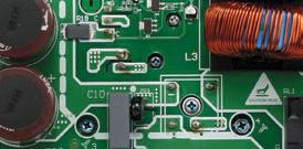
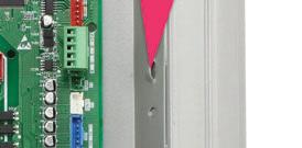
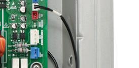
Plug in the cable connecting the Gateway to the control board fully into the green connector (Refer to Figure 27 and Figure 28).
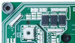
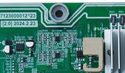
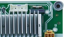
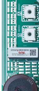
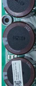
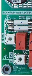
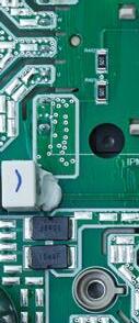
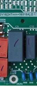
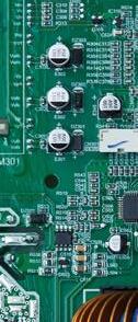
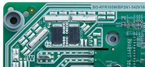
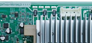

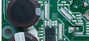
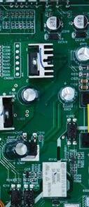
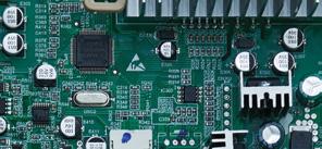
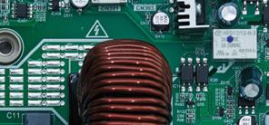
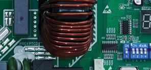
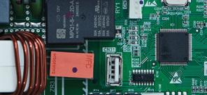
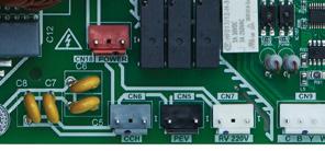
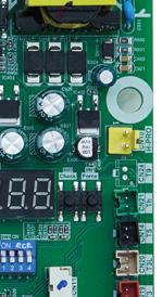
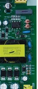
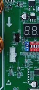
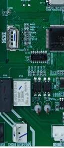
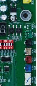
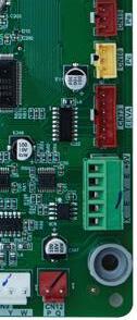

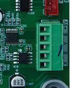
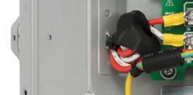
Run the antenna cable through the middle hole as shown below and push down on the cable strainer until it snaps into place (Refer to



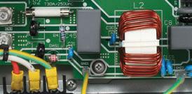
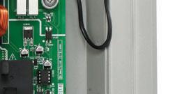
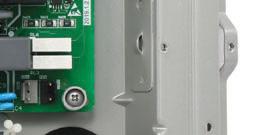
13. Bundle the wires on the right of the control board by feeding the zip-ties through the three loops on the E-box and cut off the excess zip-tie ends (Refer to Figure 30).
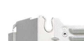
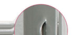
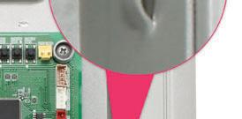
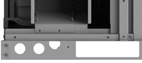
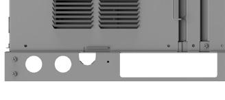
14. Route the antenna cable through the cable hole on the lower right corner of the E-Box Access Panel (refer to Figure 31).
15. Screw the control board access panel and the lower left corner panel back to the unit.
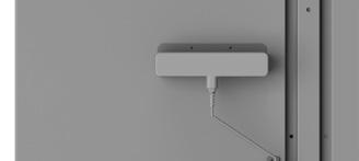
16. Install the antenna on the antenna mounting bracket by pushing down on the antenna.
17. Attach the two antenna cable clips to the antenna mounting bracket to secure the cable to the unit (Refer to Figure 32).
Ensure there is no excess tension on the cable.
18. Double-check all wire connections, grounding, and screw positions before powering the unit ON.
19. Power ON the unit and proceed to the mobile app to set up the Gateway.
20. Refer to section 7 for new Gateway activation.
6 Replacement Instructions for IDS Edge
1. Turn off power to the unit and wait at least 3 minutes.
2. Double-check all wire connections, grounding, and screw positions after the power is OFF.
WARNING
Hazardous voltage 380 volts DC!
Wait 3 minutes after disconnecting power, then verify DC voltage is less than 43 VDC at inverter test points P-N.
Components may store a dangerous electrical potential of 380 Volts DC. Failure to follow these instructions could result in personal injury or death.
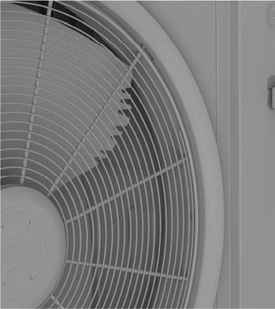
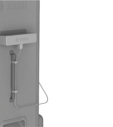
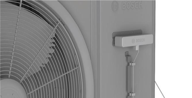
3. Remove the two antenna cable clips to the antenna mounting bracket by twisting and pulling the clips (Refer to Figure 33).
4. Remove the antenna from the antenna mounting bracket by pushing up on the antenna.
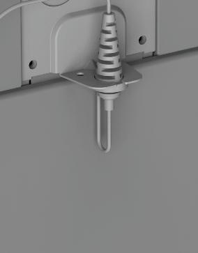
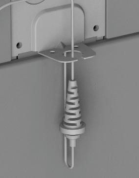
5. Remove the antenna cable strainer from the electrical knockout on the side by pulling down from the bottom of the strainer (Refer to Figure 34).


6. Remove the front right panel to access the control board (Figure
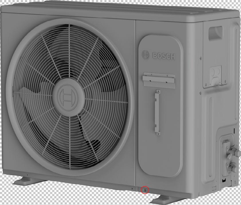
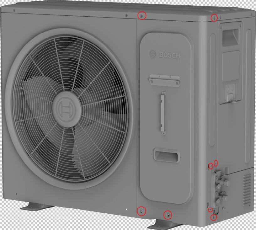
37). Keep Screws for re-use.
NOTICE
Product damage!
to
Only use the supplied sheet metal screws and ensure the screw holes are aligned to avoid damaging internal components.
NOTICE
Product damage!
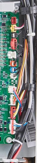
Do not directly touch the components on the main board to avoid static electricity damage.
Uninstall the Gateway by removing the two screws (Refer to )
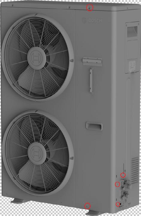
9. Old Gateway and antenna assembly should be completely removed. Proceed to Step 10.
7. Open up the cable organizers on the E-box to unbundle the wires (Refer to Figure 38).
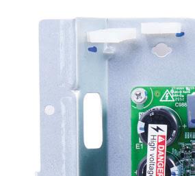
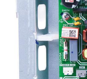
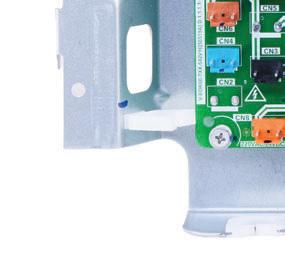

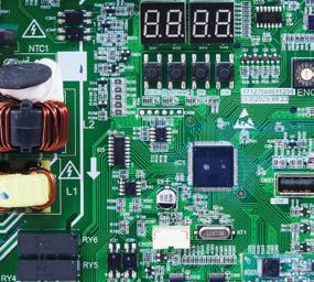
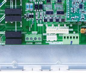
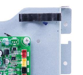
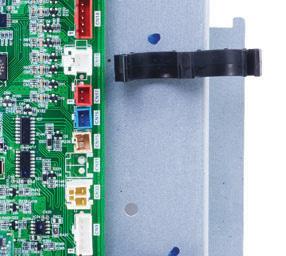
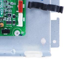
10. Install the new Gateway on the unit using 2 screws (Refer to Figure Figure 40).
Be careful not to overtighten.
11. Plug in the cable connecting the Gateway to the control board fully into the green connector (Refer to Figure 41).
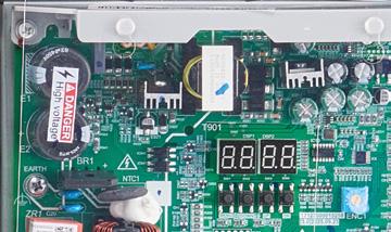
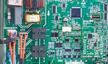
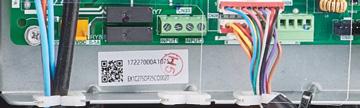


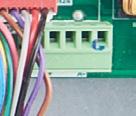
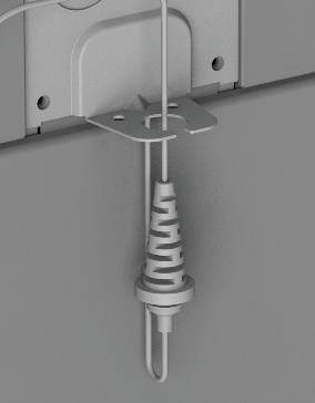
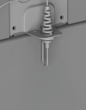
12. Run the antenna cable through the electrical knockout on the side as shown below and push up on the cable strainer until it snaps into place (Refer to Figure 42).
13. Bundle the wires on the right of the control board with the cable organizers on the E-box (Refer to Figure 38).
14. Screw the front right panel back to the unit.
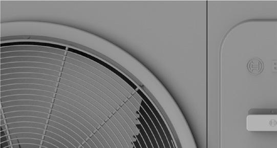
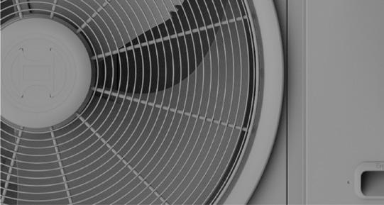
15. Install the antenna on the antenna mounting bracket by pushing down on the antenna (refer to Figure 43).
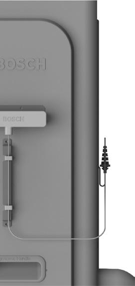
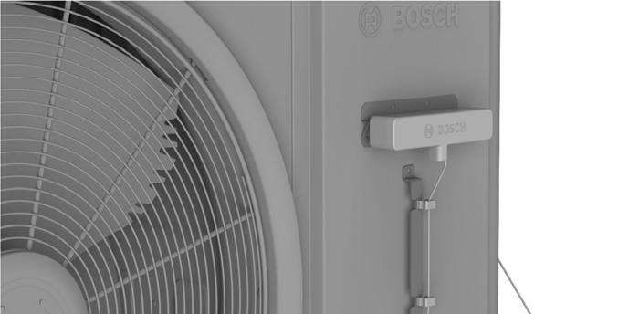
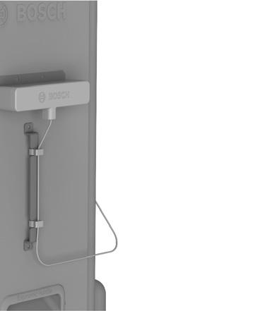
16. Attach the two antenna cable clips to the cable clip bracket to secure the cable to the unit (Refer to Figure 45).
Ensure there is no excess tension on the cable.

17. Double-check all wire connections, grounding, and screw positions before powering the unit ON.
18. Power ON the unit and proceed to the mobile app to set up the Gateway.
19. Refer to section 7 for new Gateway activation.