
12 minute read
WHITE PAPER


Chris Murphy
Advertisement
Applications Engineer, Analog Devices
Introduction
Condition-based monitoring (CbM) involves monitoring of machines or assets using sensors to measure the current state of health. Predictive maintenance (PdM) involves a combination of techniques such as CbM, machine learning, and analytics to predict upcoming machine or asset failures. When monitoring the health of a machine, it is critically important to select the most suitable sensors to ensure faults can be detected, diagnosed, and even predicted. There are many sensors currently used to sense and detect faults, in rotating machinery and their loads, with the end goal of avoiding unplanned downtime. Ranking each sensor is difficult as PdM techniques are applied to a multitude of rotating machines (motors, gears, pumps, and turbines) and nonrotating machines (valves, circuit breakers, and cables).
Many industrial motors are designed to work up to 20 years in continuous production applications such as chemical and food processing plants and power generation facilities, but some motors do not reach their projected lifetime.1 This could be due to insufficient operation of the motor, insufficient maintenance programs, lack of investment in PdM systems, or not having a PdM system in place at all. PdM enables maintenance teams to schedule repairs and avoid unplanned downtime. Early prediction of machine faults through PdM can also help maintenance engineers identify and repair motors running inefficiently, enabling increased performance, productivity, asset availability, and lifetime.
The best PdM strategy is one that efficiently utilizes as many techniques and sensors as possible to detect faults early and to a high degree of confidence, so, there is no one-sensorfits-all solution. This article seeks to clarify why predictive maintenance sensors are vital to early detection of faults in PdM applications, as well as their strengths and weaknesses.
System Fault Timeline
Figure 1 shows a simulated timeline of events from the installation of a new motor to motor failure along with the recommended predictive maintenance sensor type. When a new motor is installed, it is under warranty. After several years, the warranty will expire, and it is at this point that a more frequent manual inspection regiment will be implemented.
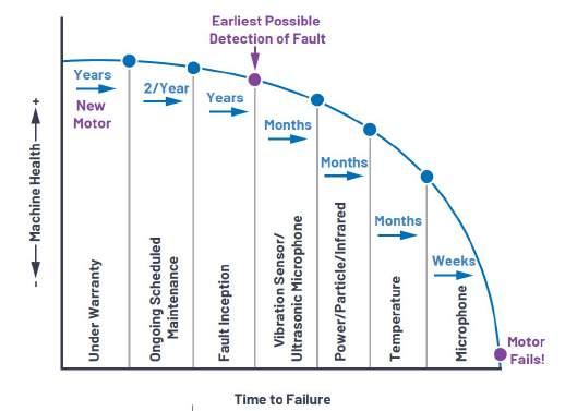
Figure 1. Machine health vs. time.
If a fault emerges in between these scheduled maintenance checks, there is a likelihood of unplanned downtime. What becomes vitally important in this case is having the right predictive maintenance sensor to detect potential faults as
early as possible and, for this reason, this article will focus on vibration and acoustic sensors. Vibration analysis is generally perceived as the best starting point for PdM.2
Predictive Maintenance Sensors
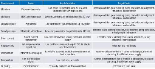
Some sensors can detect certain faults, such as bearing damage, much earlier than others, as shown in Figure 1. In this section, the sensors most commonly used to detect faults at the earliest possible moment are discussed, namely accelerometers and microphones. Table 1 shows a list of sensor specifications and some of the faults they can detect. Most PdM systems will only employ some of these sensors, so it is imperative to ensure potential critical faults are well understood along with the sensors that are best suited to detecting them.
Table 1. Popular Sensors Used for CbM Sensor and System Fault Considerations
More than 90% of rotating machinery in industrial and commercial applications use rolling-element bearings.3 The distribution of failed components of a motor are shown in Figure 2, where it is clear to see that, when selecting a PdM sensor, it is important to focus on bearing monitoring. In order to detect, diagnose, and predict potential faults, a vibration sensor must have low noise and wide bandwidth capabilities.
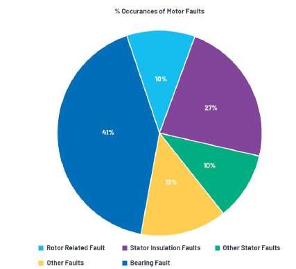
Figure 2. Percent of occurrences of failed motor components.4
Table 2 shows some of the most common faults associated with rotating machines and some corresponding vibration sensor requirements for use in PdM applications. In order to detect faults as early as possible, PdM systems typically require high performance sensors. The performance level of the
predictive maintenance sensor used on an asset is correlated to the importance of assets being continuously able to operate reliably in the overall process and not at the cost of the asset itself.
Table 2. Brief Overview of Machine Fault and Vibration
Sensor Considerations
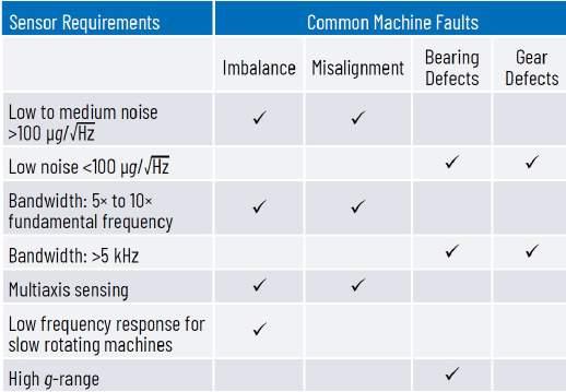
The amount of energy in the vibration or movement (peak, peak-to-peak, and rms) of a motor allows us to determine whether the machine is imbalanced or misaligned, among other things. Some faults, such as bearing or gear defects, are not as obvious, especially early on, and can’t be identified or predicted by an increase in vibration alone. These faults typically require a high performance predictive maintenance vibration sensor with low noise (<100 μg/√Hz) and wide bandwidth (>5 kHz) paired with a high performance signal chain, processing, transceivers, and postprocessing.5
Vibration, Sonic, and Ultrasonic Sensors for PdM
Microelectromechanical system (MEMS) microphones contain a MEMS element on a PCB, typically contained in a metal case with a bottom or top port to allow sound pressure waves inside. MEMS microphones offer low cost, small size, and effective means of sensing machine faults such as bearing condition, gear meshing, pump cavitation, misalignment, and imbalance. This makes MEMS microphones an ideal choice for batterypowered applications. They can be located at significant distances from the noise source and are noninvasive. When multiple assets are in operation, microphone-based performance may suffer due to the amount of audible noise from other machines or environmental factors such as dirt or humidity, accessing the port hole in the microphone. Most MEMS microphone data sheets still list relatively benign applications such as mobile terminals, laptops, gaming devices, and cameras, etc. Some MEMS microphone data sheets list vibration sensing or PdM as potential applications, but they also mention that sensors sensitive to mechanical shock and improper handling can cause permanent damage
to the part. Other MEMS microphone data sheets state a mechanical shock survivability up to 10,000 g. There is still a lack of clarity on whether some of these sensors are suitable for operation in very harsh operating environments in the presence of potential shock events.
MEMS ultrasonic microphone analysis enables the monitoring of motor health in complicated assets, in the presence of increased audible noise, because it listens to sounds in the nonaudible spectrum (20 kHz to 100 kHz) where there is far less noise. The wavelengths of low frequency audible signals typically range from approximately 1.7 cm to 17 m long. The wavelengths of high frequency signals range from approximately 0.3 cm to 1.6 cm long. When the frequency of the wavelength increases, the energy increases, making the ultrasound more directive. This is extremely useful when trying to pinpoint a failure in a bearing or housing.
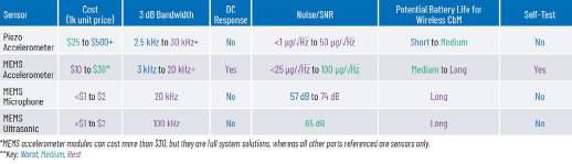
Accelerometers are the most commonly used vibration sensor and vibration analysis is the most commonly employed PdM technique, mainly used on large rotating equipment such as turbines, pumps, motors, and gearboxes. Table 3 and Table 4 show some of the key specifications for consideration when selecting high performance MEMS vibration and acoustic sensors vs. the gold standard piezo vibration sensor. Data in each column is representative of the min/max variation within that category and doesn’t correlate to adjacent columns.
The CbM industry is due to have significant growth over the next five years with wireless installations accounting for a significant amount of this growth.6 Piezo accelerometers are less suitable for wireless CbM systems due to a combination of size, lack of integrated features, and power consumption, but solutions do exist with typical consumption in the range of 0.2 mA to 0.5 mA. MEMS accelerometers and microphones are highly suited to battery-powered PdM systems due to their small size, low power, and high performance capabilities.
All sensors have suitable bandwidths and low noise, but MEMS accelerometers are the only sensors than can offer a response down to dc, useful for detection of imbalance at very low rotational speeds and tilt sensing. MEMS accelerometers also have a self-test feature where the sensor can be verified to be 100% functional. This could prove useful in safety-critical installations where meeting system standards is made easier by being able to verify if a sensor is still functional.
It is possible to completely hermetically seal MEMS accelerometers in ceramic packages and piezo accelerometers in mechanical packages for use in harsh, dirty environments. Table 4 focuses on physical, mechanical, and environmental performance of the sensors. This is where the key differences can be seen between each sensor such as integration, tolerance to harsh environments, mechanical performance, and attachment to a rotating machine or mount.
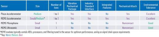
Detecting vibration data in three axes offers more diagnostic insights and can lead to better fault detection. While this is not necessary in every PdM installation, it is a distinct advantage offered by piezo and MEMS accelerometers in terms of data quality, wiring, and space savings. MEMS microphones have shown distortion of up to –8 dB when exposed to increased humidity for prolonged periods.7 While this is not a distinct weakness, it is worth considering if your PdM application exists in a harsh environment with high humidity. In such cases, electret condenser microphones (ECMs) have shown advantages over MEMS microphones. Other environmental conditions that can affect microphones are wind, atmospheric pressure, electromagnetic fields, and mechanical shock.8
In benign environments, MEMS microphones offer excellent performance in PdM applications. Currently, there is a lack of information available on mounting MEMS microphones in harsh operating environments with excessive vibrations, dirt, or humidity. Vibration can affect the performance of MEMS microphones, and this is an area that needs consideration; however, they do have lower vibration sensitivity than ECMs.9 If a wireless PdM solution were to use a MEMS microphone, the mounting box would need to have a hole or port to allow the acoustic signal to reach the sensor, adding further design complexity and potentially making other electronics susceptible to dirt or humidity. Recent advancements in capacitive MEMS accelerometer technology have allowed small, low cost, low power, wireless CbM solutions to be implemented on lower priority assets, allowing further diagnostic insights into facilities management and maintaining critical system uptime. These advancements also moved MEMS accelerometers closer to piezo performance for use in more traditional, wired CbM systems. Having such low noise and wide bandwidth, coupled with industry-standard connections (ICP and IEPE), piezo accelerometers have been the gold standard sensor used in vibration measurement for decades. MEMS accelerometers have been adapted to interface with IEPE standard modules, as shown in Figure 3. The conversion circuit is based on a Circuits from the Lab® reference design. The circuit was designed on a special PCB
that has been characterized to perform over wide bandwidths and is ready to be designed into a mechanical module at a later stage.
Figure 3. MEMS accelerometer, IEPE reference, PCB design allowin g retrofit of the ADXL100x family of CbM accelerometers in IEPE mechanical modules. Note: Analog Devices does not produce IEPE mechanical modules.
The device shown in Figure 4 contains three single-axis MEMS accelerometers, three ADCs, a processor, memory, and algorithms, all in a mechanical module with a resonance over 50 kHz. This highlights the capability of MEMS accelerometers to integrate intelligence at the sensor node, ensuring the sensor is paired with the best signal chain and processing to achieve the best performance possible. This module can perform FFTs, trigger various time domain or frequency domain alarms, and generate time domain statics vital for algorithms or machine learning tools to predict failures.
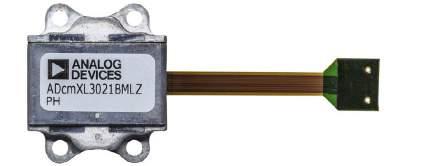
Figure 4. Three-axis MEMS CbM module with integrated ADC, processor, FFT, and statistics, as well as a mechanical package with resonant frequency over 50 kHz.
When it comes to choosing the most suitable vibration sensor for your PdM solution, the real challenge lies in pairing sensors to meet the most likely potential failure modes of your assets. MEMS microphones are not yet proven to be robust enough to reliably detect all vibration-based failure modes in the harshest of environments, whereas the industry standard for vibration sensing, accelerometers, have been successfully implemented and performed reliably for decades. MEMS ultrasonic microphones have shown promising performance in detecting bearing faults earlier than accelerometers, and this potential symbiotic relationship could deliver the best PdM solution for your asset’s vibration analysis needs in the future.
While it is difficult to recommend a single vibration sensor for use in a PdM system, accelerometers have a successful history and continue to evolve and improve. Analog Devices offers a range of MEMS accelerometers from general purpose, low power, low noise, high stability, and high g, as well as intelligent edge-node modules shown in Figure 4. The ADcmXL3021 is just one example of a dedicated PdM module solution. Analog Devices was first to market with a family of PdMcapable MEMS accelerometers (20 kHz+ bandwidth, 25 μg/√Hz noise density) and remains the only MEMS accelerometer supplier with these performance levels. Analog Devices is continuing to lead the way in providing sensors, signal chain solutions, mechanical modules, platforms, machine learning algorithms, artificial intelligence software platforms, and total system solutions to enable predictive maintenance of industrial rotating machines in the most challenging environments.
Visit analog.com/CbM or contact CIC.EMEA@analog.com for more information.
References
1 Leslie Langnau. “Sensors Help You Get Maximum Use from Your Motors.” Machine 2 Bram Corne, Bram Vervisch, Colin Debruyne, Jos Knockaert, and Jan Desmet. “Comparing MCSA with Vibration Analysis in Order to Detect Bearing Faults—A Case Study.” 2015 IEEE International Electric Machines and Drives Conference (IEMDC), IEEE, May 2015. 3 Brian P. Graney and Ken Starry. “Rolling Element Bearing Analysis.” Materials Evaluation, Vol. 70, No. 1, The American Society for Nondestructive Testing, Inc., January 2012. 4 Pratyay Konar, R. Bandyopadhyay, and Paramita Chattopadhyay. “Bearing Fault Detection of Induction Motor Using Wavelet and Neural Networks.” Proceedings of the 4th Indian International Conference on Artificial Intelligence, IICAI 2009, Tumkur, Karnataka, India, December 2009. 5 Pete Sopcik and Dara O’Sullivan. “How Sensor Performance Enables Condition- Based Monitoring Solutions,” Analog Dialogue, Vol. 53, June 2019. 6 Motor Monitoring Market by Offering (Hardware, Software), Monitoring Process (Online, Portable), Deployment, Industry (Oil and Gas, Power Generation, Metals and Mining, Water and Wastewater, Automotive), and Region—Global Forecast to 2023. Research and Markets, February 2019. 7 Pradeep Lall, Amrit Abrol, and David Locker. “Effects of Sustained Exposure to Temperature and Humidity on the Reliability and Performance of MEMS Microphone.” ASME 2017 International Technical Conference and Exhibition on Packaging and Integration of Electronic and Photonic Microsystems, September 2017. 8 Marcel Janda, Ondrej Vitek, and Vitezslav Hajek. Induction Motors: Modelling and Control. InTech, November 2012. 9 Muhammad Ali Shah, Ibrar Ali Shah, Duck-Gyu Lee, and Shin Hur. “Design Approaches of MEMS Microphones for Enhanced Performance.” Journal of Sensors, Vol. 1, March 2019.
About the Author
Chris Murphy is an applications engineer with the European Centralized Applications Center, based in Dublin, Ireland. He has worked for Analog Devices since 2012, providing design support on motor control and industrial automation products. He holds an M.Eng. in electronics by research and a B.Eng. in computer engineering. He can be reached at christopher.


