13 minute read
Designing Ammonia Systems for Maintenance and Safety

Designing Ammonia Systems Maintenance Safety
and for
Advertisement
By Gary J. Webster, Kraft Foods Global, Inc.
(The goal of design and maintenance is to account for the safety of workers and the nearby community given the inherent risks of ammonia. Properly designed, maintained, and operated, these systems can be safe. The examples provided in this article highlight protective ways of meeting this goal, though there may be similarly protective alternate ways of designing, maintaining, and/or operating an ammonia system.)
Introduction
Proper design, maintenance and safety is critical for operator safety; ammonia system and equipment reliability, functionality and efficiency; and protecting facility assets. Although this paper does not touch on all aspects of design, it briefly highlights examples for implementing long term safety, system and equipment reliability, and efficiency.
Ammonia system design should only be performed by qualified engineering companies and/or design/build contractors. When designing an engine room, location, size, equipment layout, future expansion, construction materials, future maintenance, etc. all need to be considered. The topics in this paper apply to designing a new engine room, or modifying or expanding an existing engine room. The statements in this paper do not state a company position or definitive view and are based on my personal observations during the course of my career.
Initial Design
It is extremely important to hire an experienced and qualified engineering design firm or an ammonia design/ build contractor. In addition, during the design stage, it is important to have facility engineers, utility supervisors and refrigeration operators involved in design reviews. Consider having design reviews, with all parties involved, at various stages, such as initial, 30 percent, 60 percent and 90 percent completion. Several of these reviews can be by conference call, but face-to-face is recommended at least for a 60 percent review. It may seem excessive, but reviewing often maintains project focus with all involved parties and allows for easy modifications and revisions, typically without major expense.
In the initial design stage, consider performing a Hazard Analysis for any new engine room or major modification or expansion. The Hazard Analysis can be of several methods such as HAZOP, What-if or What-if Checklist. The Hazard Analysis should be performed by a person familiar with the hazard analysis technique being used and is an excellent method for analyzing the system and eliminating potential safety hazards during the design stage.
Once a qualified engineering design firm and/or design build contractor is chosen, the design team can consider engine room location options. Consider adjacent buildings
Designing Ammonia Systems for Maintenance and Safety continued from page 4 and rooms within the property boundaries as well as buildings adjacent to the property when designing. Additional on site considerations such as main employee plant entrances, offices, parking lots, distances from property line, basement locations and confinement within production facilities are important. Where practical, remote separate buildings, far corners of properties, areas downwind of prevailing winds, and a safe distance from neighboring properties are excellent locations for engine rooms.
After site location is determined, system design decisions such as built-up or package units, flooded or direct expansion (DX) units, glycol or direct ammonia to the load, process temperatures required, etc. need to be analyzed and discussed. Although not as efficient as direct ammonia cooling, using a secondary medium such as glycol has safety advantages. Pumping glycol to the load and keeping the ammonia in the engine room minimizes potential ammonia exposure and leaks in the plant. Consider advantages and disadvantages of each option in the design.
During the design stage, consider evaluating energy saving opportunities and options. They can be included in the design or bid as alternatives. Tax incentives or credits are often available through local utility companies for energy saving equipment/projects.
Energy items to consider in the design phase include proper suction pressure to run the system, a single or a two stage system, integral sump vs. remote sump for evaporative condensers, various floor warming methods, variable frequency drives (VFD’s), over sizing condensers and evaporators, defrost schedule programming, fan types, fan cycling, compressor sequencing, evaporator fin spacing, compressor oil cooling method, condenser type, condenser spray nozzles, premium efficient motors, liquid sub cooling, heat recovery, dock door types, warehouse lighting, etc.
Designs for Safety
All local, city and country rules, regulations, codes and laws need to be followed on all designs. Regardless of the examples suggested in this paper, you should follow your applicable local laws at a minimum.
If local or country rules/regulations/codes do not determine egress, consider at least two methods of egress from an engine room with at least one exit directly to outside. Exits from an engine room need to remain un-obstructed and free of clutter and debris. Strategically locate eyewashes/showers in unobstructed areas in the engine room. Another consideration is having an eye wash/shower outside the engine room in case the ammonia concentration is too high to remain in the engine room. It is good design to provide eyewash/safety showers with tepid water.
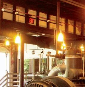
Continuous and emergency engine room ventilation fans (Figure 1) are typically required and sized per local or country rules/regulations/codes. Emergency exhaust fans are typically up- blast type with the motor located outside of the air stream. Wall louvers can be provided to allow fresh air into the engine room. Good design for an engine room layout will have fans located on one end of the engine room and wall louvers on the opposite end so air sweeps through the engine room and exhausts a safe distance from air intakes, windows and doors. Emergency Exhaust Fan SRV Header Discharge Figure 1. Emergency Exhaust FanFigure 1. Emergency Exhaust Fan Emergency Exhaust Fan Ammonia sensors strategically located in engine rooms are typically part of good design. Often
Ammonia sensors strategically located in engine rooms are low level sensors (sensors set to detect low ppm concentrations of ammonia) are used to sound typically part of good design. Often low level sensors (sensors an alarm, activate a strobe light outside the engine room doors and start high velocity emergency exhaust fans. In addition, low level sensors typically activate motorized wall louvers to allow set to detect low ppm concentrations of ammonia) are used fresh outside air to be drawn into the engine room. to sound an alarm, activate a strobe light outside the engine High level ammonia sensors often activate a shunt trip on a main breaker supplying electrical SRV Header Discharge room doors and start high velocity emergency exhaust fans. power to the engine room. Shunt tripping the electrical power when the ammonia concentration
In addition, low level sensors typically activate motorized wall nears the explosive level eliminates electrical spark sources and reduces the risk of an explosion. louvers to allow fresh outside air to be drawn into the engine room. If a shunt trip system is applied, explosion proof emergency lights and emergency exhaust fans are typically installed on a separate power source. In the event of a shunt trip, the motorized wall
High level ammonia sensors often activate a shunt trip louvers should Ôfail open,Õ in other words, you want the louvers to open. Figure 1. Emergency Exhaust Fan on a main breaker supplying electrical power to the engine Break glass stations (Figure 2) are often required by code. If not, consider installing break glass Ammonia sensors strategically located in engine rooms are typically part of good design. Often room. Shunt tripping the electrical power when the ammonia stations for immediate electrical shunt trip of all engine room power except explosion proof low level sensors (sensors set to detect low ppm concentrations of ammonia) are used to sound concentration nears the explosive level eliminates electrical sparkemergency lights and exhaust fans. an alarm, activate a strobe light outside the engine room doors and start high velocity emergency sources and reduces the risk of an explosion. If a shunt trip systemexhaust fans. In addition, low level sensors typically activate motorized wall louvers to allow fresh outside air to be drawn into the engine room. is applied, explosion proof emergency lights and emergency exhaust fans are typically installed on a separate power source. Break Glass Station High level ammonia sensors often activate a shunt trip on a main breaker supplying electrical power to the engine room. Shunt tripping the electrical power when the ammonia concentration In the event of a shunt trip, the motorized wall louvers should ‘failnears the explosive level eliminates electrical spark sources and reduces the risk of an explosion. open,’ in other words, you want the louvers to open. If a shunt trip system is applied, explosion proof emergency lights and emergency exhaust fans are typically installed on a separate power source. In the event of a shunt trip, the motorized wall Break glass stations (Figure 2) are often required by code. louvers should Ôfail open,Õ in other words, you want the louvers to open. If not, consider installing break glass stations for immediate electrical shunt trip of all engine room power except explosion Break glass stations (Figure 2) are often required by code. If not, consider installing break glass stations for immediate electrical shunt trip of all engine room power except explosion proof proof emergency lights and exhaust fans.emergency lights and exhaust fans. Figure 2. Break Glass Station Safety relief valves (SRV) are typically piped into a properly sized common header and piped to the roof. Good design locates the discharge a safe distance from all air intakes, windows and Break Glass doors and protected from rain and snow by turning the pipe downward, cutting at a 45¡ angle or Station by use of a diffuser. In addition, when terminating SRV discharge headers, consider whether moisture from cooling towers or evaporative condensers could enter the pipe discharge. If water from these sources does enter the pipe, it could freeze and break. When piping SRV headers to a Figure 2. Break Glass StationFigure 2. Break Glass Station Safety relief valves (SRV) are typically piped into a properly sized common header and piped to the roof. Good design locates the discharge a safe distance from all air intakes, windows and doors and protected from rain and snow by turning the pipe downward, cutting at a 45¡ angle or by use of a diffuser. In addition, when terminating SRV discharge headers, consider whether moisture from cooling towers or evaporative condensers could enter the pipe discharge. If water
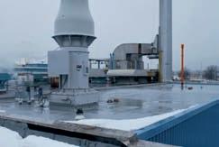
Figure 3. Float Switch
Safety relief valves (SRV) are typically piped into a properly sized common header and piped to the roof. Good design locates the discharge a safe distance from all air intakes, windows and doors and protected from rain and snow by turning the pipe downward, cutting at a 45° angle or by use of a diffuser. In addition, when terminating SRV discharge headers, consider whether moisture from cooling towers or evaporative condensers could enter the pipe discharge. If water from these sources does enter the pipe, it could freeze and break. When piping SRV headers to a roof, a good design is to install a drip leg with a stainless steel ball valve with weep hole on the low point located in the engine room to Figure 3. Float Switch periodically check and drain moisture. Engine room access is typically limited to authorized Designs for Maintenance personnel only. Consider posting signage on the exterior of It is extremely important to lay out equipment with ample all doors into the engine room stating Authorized Personnel working distances and clearances. If codes/regulations/ Only. To safeguard engine rooms from entry by un-authorized rules do not require a minimum working distance, consider a personnel, doors are typically locked from the outside and minimum of one meter (3.3 ft.) in front of all electrical panels access permitted only by key, badge swipe, combination and 1.2 – 1.5 meters (4 -5 ft.) between compressors, chilled code or some other secure method. water pumps, etc. Consider double doors or an overhead
Alarms are a critical part of ammonia room designs, door into the engine room for equipment maintenance removal especially in remote engine rooms or facilities with minimal and future installations. In addition, compressor and motor refrigeration operators. Alarms can be installed to notify removal for maintenance/replacement can be made easier personnel of compressor failures, ammonia leaks, fires, pump by designing lifting hoists, such as an overhead trolley and an shut downs, system upsets, etc. It is important to involve I-beam system with chain hoists. refrigeration operators to determine which alarms and Evaporative condensers and/or cooling towers are often notification methods are preferred. System upsets can be located on the roof. Consider stairs with hand rails instead alarmed at security offices/gates, cell phones, computers, etc. of ships ladders to the roof for easier maintenance access.
Good design practice considers valve accessibility, piping If access to the roof is through the engine room by stairs, methods for reducing potential leaks and future expansions. consider a door onto the roof instead of a roof hatch. In An example of a good design practice for future expansion cold weather locations ice and snow could make opening a includes adding a valve and bleed valve on the stub end roof hatch difficult. Galvanized structural steel platforms for of pipes, thus eliminating a shutdown when expanding the condensers will eliminate future maintenance costs required for header. painted steel.
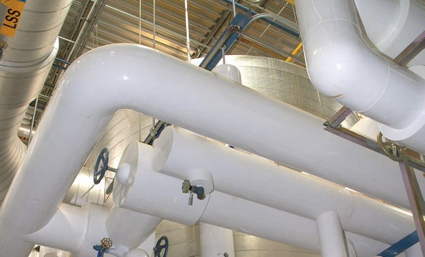
In some situations, locating overhead valves high in the Consider upper and lower catwalks around evaporative ceiling cannot be avoided. When installing overhead valves, condensers (Figure 4) for servicing fans, motors, pumps and consider how the equipment located directly below the sprays. Without easy access, maintenance and daily checks valve impacts valve accessibility. When it is difficult to avoid may be more difficult and less safe. In addition to catwalks, installing valves overhead or above equipment, chain operated condenser manufacturers often have options such as motor/fan valves can be installed to improve valve accessibility. jib cranes for easy removal of fan motors.
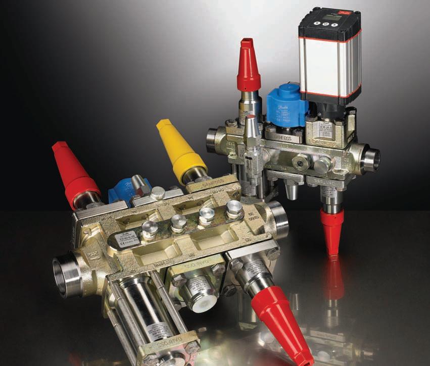
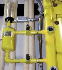
Pipe flanges, threaded connections and unions are a potential source of leakage. Consider welded connections when installing equipment, including items such as float switches (Figure 3) and sight columns. Typically, float switches and sight columns are installed with flanges. Since the bottom connection on a float switch or sight column is typically below liquid level, the risk of an ammonia leak is increased.
Installed with no flanges or unions to eliminate potential leaks
Designs for Maintenance
It is extremely important to lay out equipment with ample working distances and clearances. If codes/regulations/ rules do not require a minimum working distance, consider a minimum of one meter (3.3 ft.) in front of all electrical panels and 1.2 Ð 1.5 meters (4 -5 ft.) between compressors, chilled water pumps, etc. Consider double doors or an overhead door into the engine room for equipment maintenance removal and future installations. In addition, compressor and motor removal for maintenance/replacement can be made easier by designing lifting hoists, such as an overhead trolley and an I-beam system with chain hoists. Evaporative condensers and/or cooling towers are often located on the roof. Consider stairs with hand rails instead of ships ladders to the roof for easier maintenance access. If access to the roof is through the engine room by stairs, consider a door onto the roof instead of a roof hatch. In cold weather locations ice and snow could make opening a roof hatch difficult. Galvanized structural steel platforms for condensers will eliminate future maintenance costs required for painted steel. Consider upper and lower catwalks around evaporative condensers (Figure 4) for servicing fans, motors, pumps and sprays. Without easy access, maintenance and daily checks may be more difficult and less safe. In addition to catwalks, condenser manufacturers often have options such as motor/fan jib cranes for easy removal of fan motors. Figure 4. Evaporative Condenser Catwalks Older designs often located pipes and valve stations inside buildings and tight to ceilings and/or above a false or drop ceiling. Valve access was often difficult with this design and shutting off valves in an emergency could be dangerous. Modern design typically locates pipe mains and valve stations on roofs. This design practice allows easy access to shut off ammonia to a room and/or an evaporator in case of a leak. In addition, maintenance on valve stations located on roofs is typically easier and safer.
Catwalks
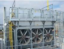
Figure 4. Evaporative Condenser Catwalks