4 minute read
Line width applications

from BCN3D Slicing Guide eBook
by BCN3D
Surface details
When your 3D model includes surface details that are smaller than the hotend size, BCN3D Stratos ignores them. However, if you slightly reduce the Outer Wall Line Width, you may print those features successfully.
Advertisement
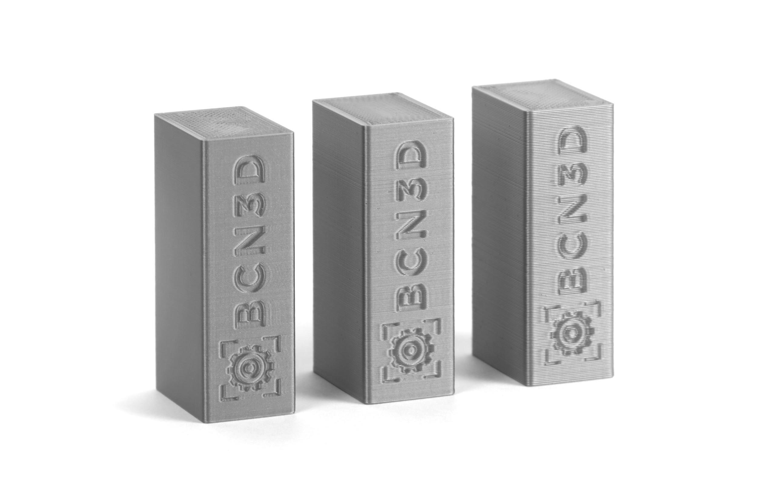
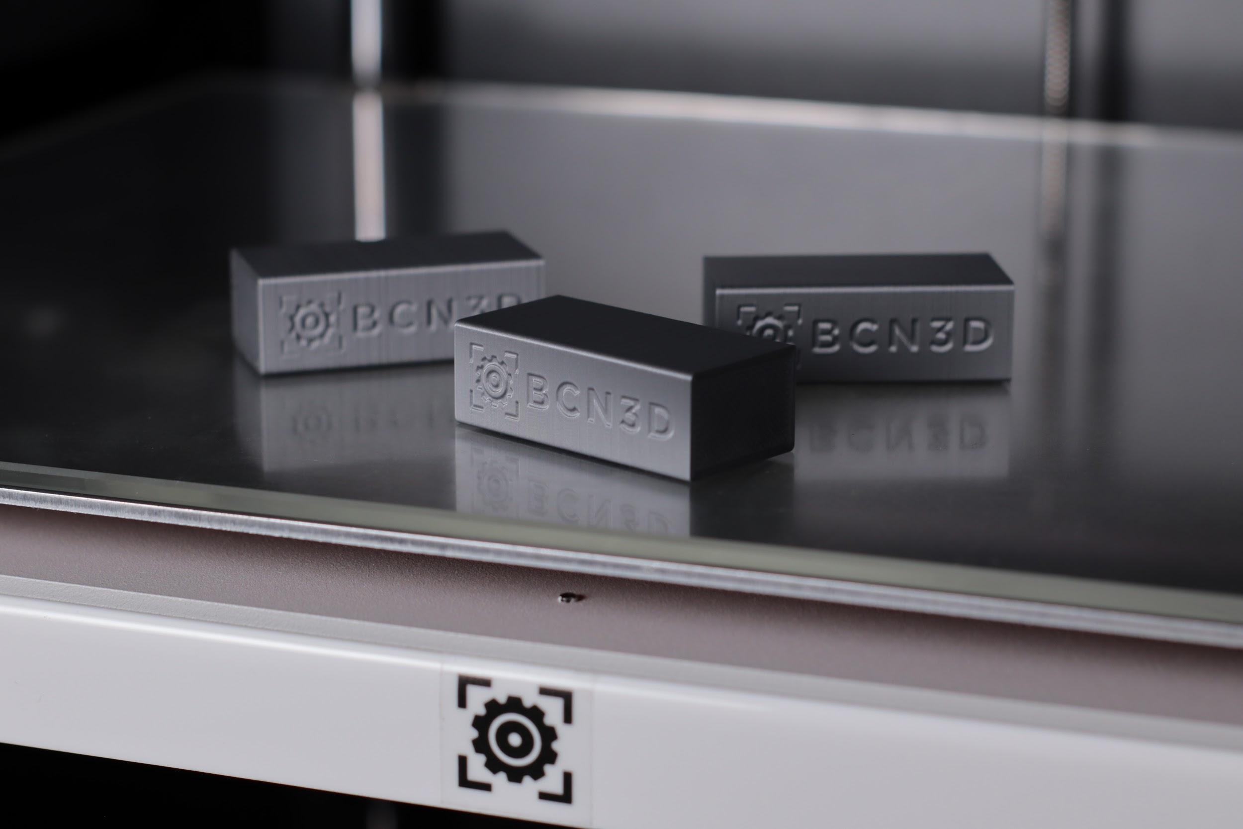
For example, many 3D models include text that offers indications when using the product. The product from the image below has two almost identical components. One must go on the right and the other on the left.
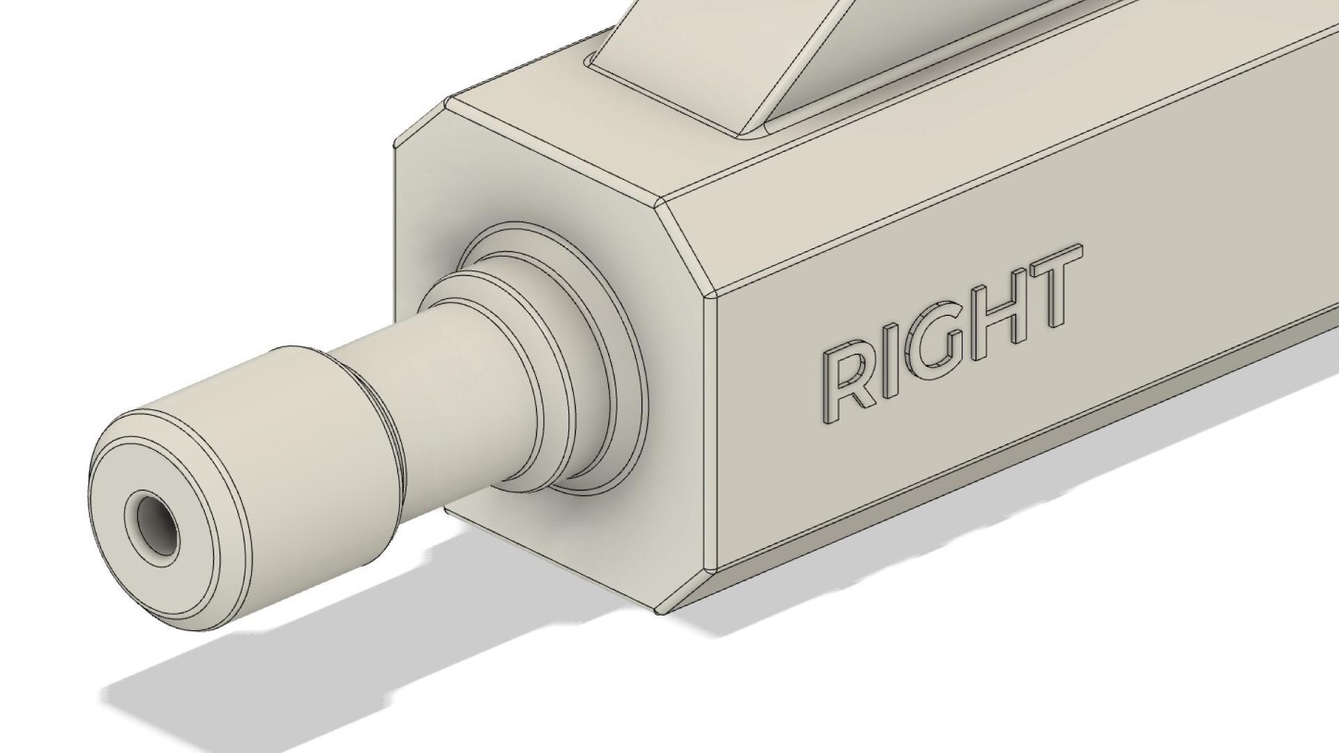
The design is optimized for 3D printing, and the text (RIGHT) uses a sans serif font that increases readability. It’s also extruded 0.4mm, which corresponds to the hotend size. However, when slicing the model in BCN3D Stratos, the text disappears as the stroke thickness isn’t large enough.
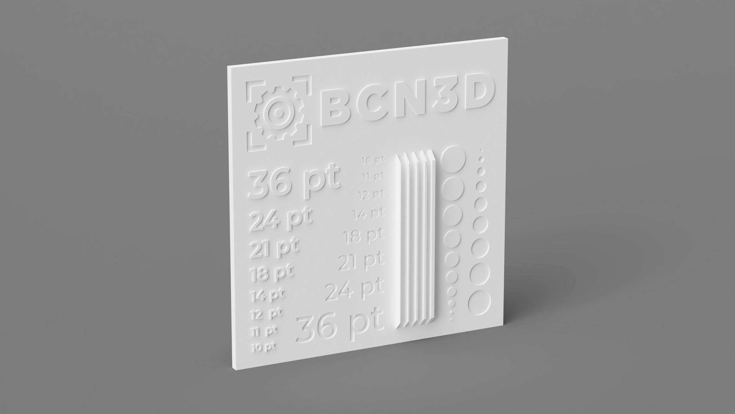
Using test models to identify the best feature size for your designs will help you improve your design skills and understand how to make the best out of your 3D printer.
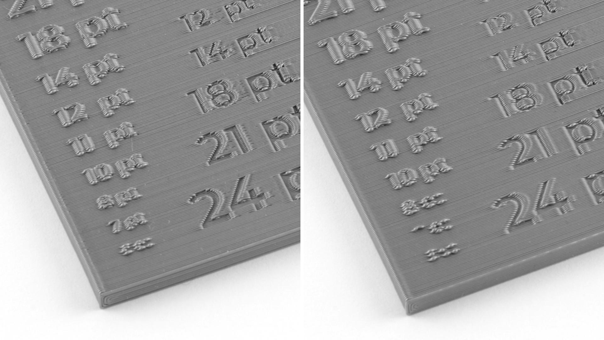
Outer Wall Line Width test comparison: 0.35mm (left), 0.4mm (right)
In the example above you can see how small text sizes such as 7 pt are only printed when the Outer Wall Line Width is reduced to 0.35mm.
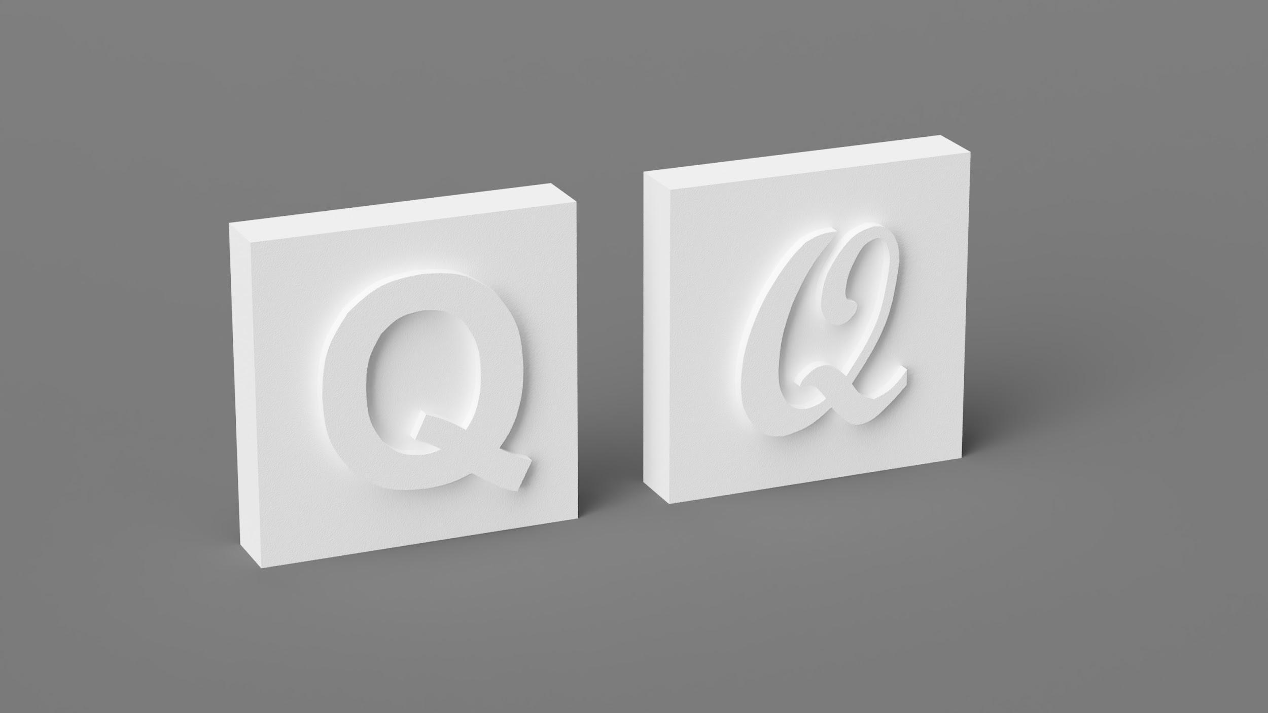
If your 3D models include text, use sans serif fonts, bold text, and large font sizes. Handwritten fonts usually require a large font size to compensate for the inconsistent stroke width.
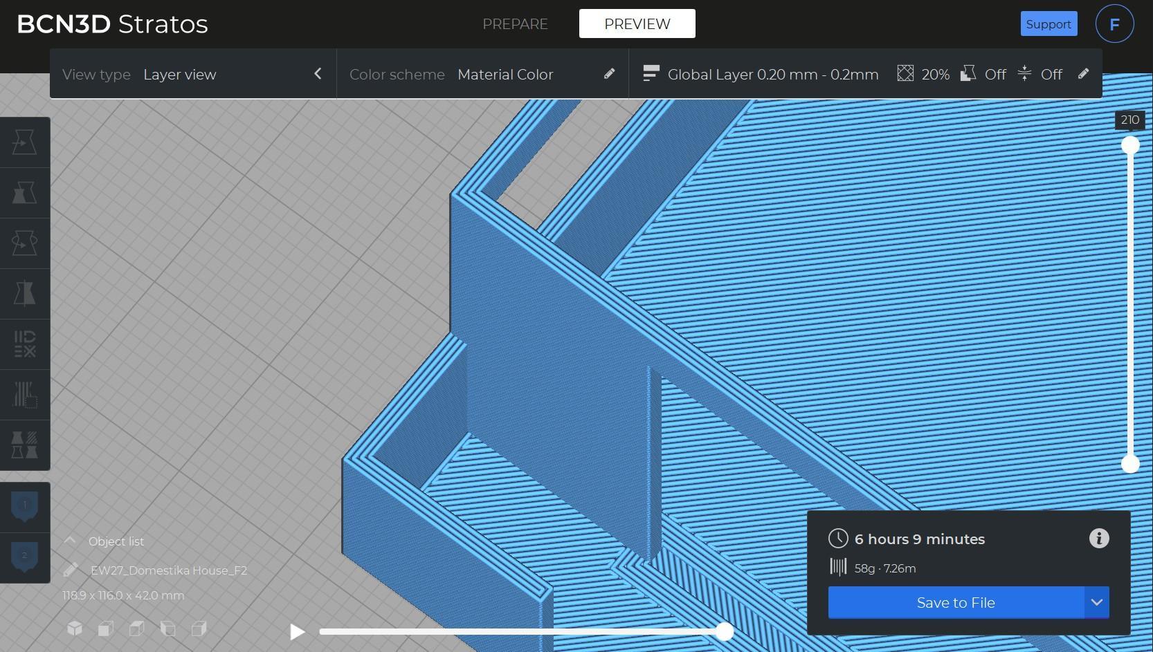
The Line Width settings are also helpful in those cases where complex shapes and textures need to be printed as one single part. For example, architectural models usually include vertical walls that have a variable thickness. Some of them may be too thin to be 3D printed. In those cases, using a smaller line width can help achieve better overall quality.
Bed adhesion
There are many ways to guarantee excellent bed adhesion, including using the right bed temperature, leveling the build plate, or using glue. However, there’s one more way to improve bed adhesion: The Initial Layer Line Width.
This setting increases the first layer's line width, affecting all the line widths, including walls, supports, infill and skin. All these settings are multiplied by the Initial Layer Line Width.
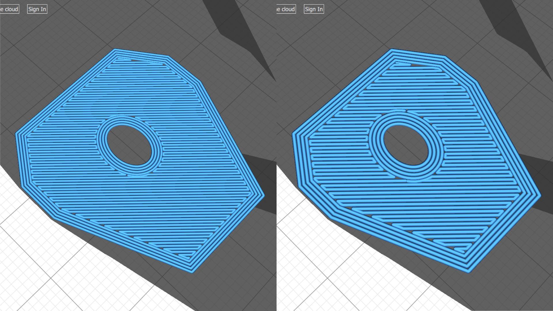
Initial Layer Line Width comparison: 100% (left), 130% (right)
As you can see in the example above, when the Initial Layer Line Width is increased, all the extruded lines thicken, but the part size remains the same. To avoid over extrusion, when you increase the Initial Layer Line Width, the distance between lines is also increased.
But, how does this improve bed adhesion? As more material is extruded in the first layer, it’s pressed harder against the build plate, increasing the adhesion between the printed part and the bed.
Mechanical properties
If you want to print a stronger part fast, the Line Width is a setting you’ll want to consider.
Make slight adjustments to the part strength by increasing the Infill Line Width from 0.4mm to 0.6mm instead of increasing the infill percentage. This way, your part’s infill will be thicker and more resistant while the print time remains the same.
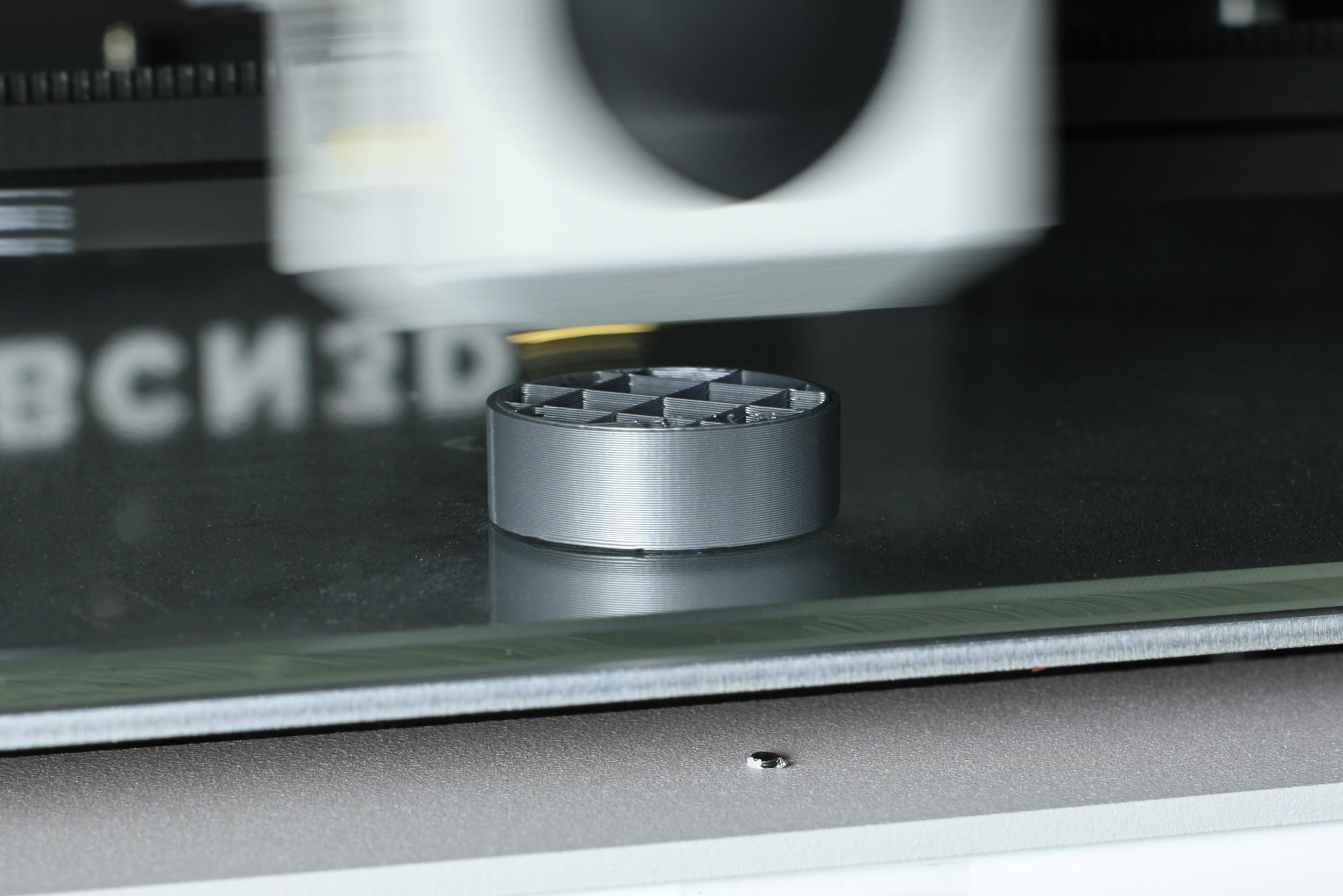
In the following example, the Infill Line Width was increased from 0.4mm (standard Line Width) to 0.6mm while using a Grid infill pattern.

Infill Line Width comparison: 0.4mm (left), 0.6mm (right)
The number of infill lines is automatically reduced to guarantee an accurate infill percentage. If the infill grid had been identical, the additional material that would be extruded would increase the infill percentage, not by adding more lines but by simply adding more material on the inner part of the model.
The two main benefits when increasing the Infill Line Width are:
● Reduced print time: When the Infill Line Width is increased, the number of infill lines reduces, which also reduces the print time. In this example, the print time went from 273 minutes to 243 minutes—an 11% print time reduction.
● Increased strength: Using larger hotends leads to an increase in part strength. However, by slightly changing the Line Width, you can get similar results using a smaller hotend.