7 minute read
Case study: Seeing past the fault code


By Edward Grigg, Swanley Garage Services
Vehicle: 2011 Audi A5 2.0 Diesel
I was asked to look at a 2011 Audi A5 2.0 – the glow plug light was illuminated and the customer was complaining of an Electronic Stability Program, ESP and parking brake fault, together with a loss of power – all of which happened at the same time. I confirmed the customer’s complaint, connected my Bosch diagnostic computer and carried out a global scan of the vehicle.
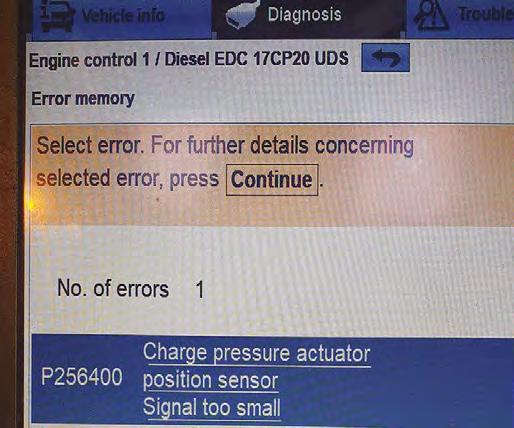
I found three fault codes: P0651 sensor reference Voltage B open circuit; a U code for ABS/ESP CAN signal faulty, and one in the parking brake module complaining of a fault within the engine control module, see Figure 1. At first glance, I believed the reason for the ESP and handbrake warning light was due to the fault in the engine control module. My thoughts were that if I tackled and fixed the engine fault, I would, in turn, fix all the faults.
I had a look through the various technical information software to see if I could find any information on which sensors could be on sensor reference B. Unfortunately, there was no information regarding this. Drawing a blank, I decided my next step would be to go through live data to see if I could find any sensor readings outside of their desired range. I checked MAF, fuel rail
Figure 1 pressure and EGR position – all of which seemed OK. I moved onto the turbo position sensor and boost pressure sensor. It was here that I found some live data that I felt was outside of the desired range. Boost pressure nominal was 1050 Mbar (atmospheric pressure) and the sensor was reading only 200 Mbar, see Figure 2. The boost pressure sensor voltage was also reading 0.247 volts in live data. Sensors generally operate between 0.5 and 4.5V, to allow for self-diagnosis if the signal voltage falls outside of this desired range.

I decided to follow this line of diagnosis so I pulled up a wiring diagram and hooked up my PicoScope to the boost pressure sensor and turbo position sensor. Straight away I found that there was no sensor supply voltage to either of these sensors. I unplugged the boost pressure sensor whilst monitoring the scope to see if it made any difference, it didn’t. Whilst it was unplugged, I load tested the sensor ground (which was
Figure 2
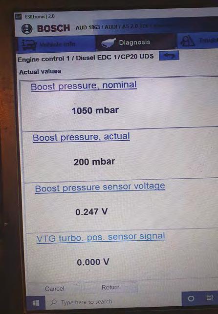
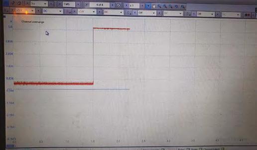
Figure 3
good) and refreshed the fault codes to see if there were any changes. The ECU flagged a new fault code for IAT/Boost pressure sensor open circuit and the original P0651 sensor reference voltage B remained. I then plugged the boost pressure sensor back in, keeping the PicoScope monitoring the sensor supply voltage.
Moving on, I unplugged the turbo position sensor whilst once again monitoring the PicoScope, see Figure 3. As I unplugged the turbo, the 5V sensor supply voltage came back to life on both the boost pressure and turbo position sensor. Again, I decided to refresh the fault codes and I had rectified the original code of P0651 but now had a code solely related to just having the turbo position sensor unplugged, see Figure 4.
The interesting thing is that the wiring diagrams show that the two sensors are not linked in any way, so how could one sensor affect another? This is because in reality they are linked together inside the ECU. Knowing this was one of the key factors of understanding how the different sensor circuits work.
The turbo position sensor was internally shorting the 5V sensor supply voltage to ground. I was happy to go ahead and fit a new turbo knowing that this would fix the fault. I decided to gather my apprentices and show them how I managed to tackle this issue. They found this fault particularly interesting because the original fault code gave no indication to which component was at fault.
Figure 4