5 minute read
Critical components for operational safety

Power plants are essential in supporting our global infrastructures; generating vital electricity for the populations they serve. Auramarine products help power plants to operate as efficiently and effectively as possible by performing critical fuel supply roles. Through selecting the most suitable parts, the service life of a power plant can not only be extended but run without technical disruption.
Solutions to suit every station
Advertisement
Auramarine units are used for pumping, filtering impurities, heating and cooling, viscosity control, and many other functions at piston-engine operated power plants, and power stations, running on a variety of fuels, such as heavy fuel oil (HFO), light fuel oil (LFO), crude oil, biofuels, or gas. The units ensure that the fuel reaches the engine clean, at the optimum pressure and temperature and in accordance with engine maker’s specifications.
With experience from approx. 2000 units delivered to power plants and stations globally we are committed to ensuring that your fuel supply system delivers the best operational safety and performance
In addition to fuel supply systems and components, we also deliver parts and units for lubrication and cooling purposes.
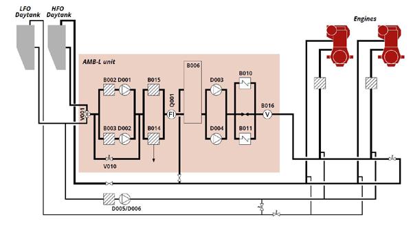
Typical fuel supply system components and options
HFO/LFO 3-way changeover valve, V001 for selecting fuel and flushing the system. The changeover valves and feeder pumps can be ordered as separate units. Manual or remote controlled
Suction strainers B002, B003 for protecting the pumps
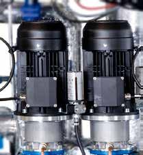
Feeder pumps, D001, D002 for pressurising the system with fresh fuel according to the consumption of the engines, equipped with an automatic stand-by function. Magnetic or mechnanical couplings
Pressure control valve V010 for maintaining constant system pressure at different loads. With or without bypass
Automatic filter with bypass filter, B014,
B015 for removing impurities from fuel oil and indication of failures in purification system, equipped with automatic cleaning and pressure difference indication. Sizes: 34 / 25* / 10* µm in cold side, 48 / 34 / 25* µm in hot side (*certain fuel types and flows call for a larger frame)
Flow meter Q001 for indicating fuel consumption. With local totalizer and output signal. Available as mass or volumetric type. Mixing tank B006 for mixing the return fuel from the engines with fresh fuel and for compensating for temperature and pressure changes. Manual or automatic deaeration
Booster pumps D003, D004 for further pressurising and circulating fuel to the engines, equipped with an automatic stand-by function. If needed, an own circulating pump can be delivered for each engine. Magnetic or mechanical couplings
Fuel heaters B010, B011 for heating the fuel oil to injection viscosity, controlled via viscometer. Steam heating (SS), Thermal oil heating (TT) or Electric heating (EE)
Viscosity control system B016 for measuring the fuel viscosity and controlling the power of the heaters to maintain constant injection viscosity, secured by a temperature controller
One or two LFO pumps D005, D006 for a separate LFO
If a separate feeder unit is ordered then the booster unit does not include feeder pumps
Auxiliary units
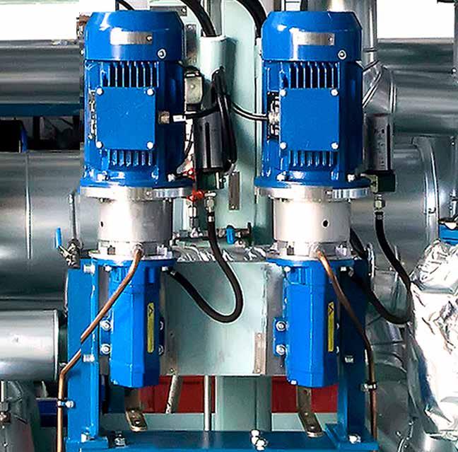
Feeder unit (AMF)
The Auramarine feeder unit (AMF) is designed to supply fuel oil to engines or HFO booster units. The unit is composed of two main elements: an operating pump and a standby pump, with the standby pump used as the reserve pump for service periods. The standby pump can be delivered as a separate module, if required

Auramarine Feeder Unit (AMF)
Auramarine
Lubrication unit
Auramarine’s Lubrication Oil Units are primarily used for pumping and filtering. The Lubrication Oil Units can also be used for the cooling of lubrication oil when necessary. The units are easy to use and can be tailored to meet the lubrication oil handling needs of your specific system configuration.
Auramarine Lubrication Oil Unit
Auramarine
HT-water preheating unit (APU)
APUs are typically used to keep the engine block warm for easy start-ups and to avoid heat tension in the engine. Auramarine’s preheating units (APUs) heat the water used in an engine’s high temperature (HT) water system. The heat is generated via steam or burning thermal oil. APUs are equipped with an associated HT-water circulation pump, which provides a continuous flow of heated water. The water temperature is kept constant by a built-in selfactuating thermostatic controller located in the unit. APUs can be remotely controlled or operated from a control cabinet mounted on the unit. For heat adjustment, thermostat valves or PID-controlled valves can also be supplied for the HT-water system needs, depending on where the HT-system’s excess heat is directed to. Additional pressure gauges and a thermometer are available as optional extras.

HT water preheating unit (APU)
Auramarine
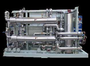
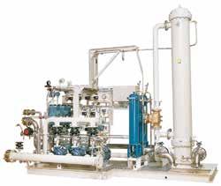
Customer-specific solutions with AMB-L -series
Auramarine fuel supply units for power plants are configurated to meet each power plant’s requirements. Configurations can comprise separate feeder and booster units, a combined feeder-booster unit, a steam-based, thermal oil or electric heating system, LFO cooling unit, gas valve units, flowmeters, filtering or viscosity control and automated heating.

AMB-L -series fuel supply unit
Auramarine
Main features
Can be extensively customised to meet all fuel system-specific requirements Proven reliability and safety from shell- or plate type heaters and separate viscosity and temperature controls Fast, easy installation delivered through a compact design and versatile connections Easy operation: all important displays and instruments are visible at a glance Long and extremely reliable service life from quality components, carefully chosen materials and advanced manufacturing
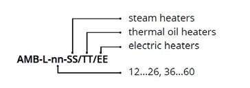
Sizes:
The L-series is available in eight different size classes, according to the total engine power to be served.The number refers to the engine power in MW and the letters that follow represent the heater type. Several units can be combined to reach the specified power output.
AMB-L 12…26
• Maximum power serviceable: 25MW • Dimensions, including service space: minimum 3.60m x 2.20m • This frame size can expand depending on optional additional features
AMB-L 36…60
• Maximum power serviceable: up to 60MW • Dimensions, including service space: minimum 5.00m x 2.60m. • This frame size can expand depending on optional additional features