
What's New
Bright Ideas for a Bright Future

AUGIWORLD brings you the latest tips & tricks, tutorials, and other technical information to keep you on the leading edge of a bright future.

Letter from the Editor

One of my favorite issues; What’s New! Here we are halfway into the year already.
Software in 2026 is defined by AIdriven automation, massive performance gains, and deeper cloud-native integration across every major platform. This year’s releases focus on reducing manual effort, improving interoperability, and delivering faster, more intelligent user experiences—whether you’re designing, analyzing data, managing operations, or collaborating across teams.
Key Themes Across 2026 Software Releases
• AI Everywhere — Tools now embed contextual AI that predicts user intent, automates repetitive tasks, and generates content, code, or insights with minimal input. AI copilots are no longer addons—they’re core features.
• Performance at Scale — Major engines and frameworks have been rebuilt for speed, with faster startup times, reduced memory usage, and GPUaccelerated workflows becoming standard across creative, engineering, and analytical software.
• CloudConnected Workflows — Applications sync more seamlessly across devices and teams, with realtime collaboration, version tracking, and cloudhosted resources replacing local configuration headaches.
• Unified Data Ecosystems — 2026 software emphasizes interoperability: shared data formats, open APIs, and crossplatform connectors that eliminate silos and reduce rework.
• Enhanced Security & ZeroTrust Defaults — Security updates focus on identitybased access, automated threat detection, and encrypted-by-default data handling to meet rising compliance demands.
• Immersive Visualization & Simulation — From 3D environments to digital twins to advanced analytics dashboards, visualization tools are more responsive, more accurate, and more accessible to nonexperts.
I hope you enjoy this month’s issue. If you want to write something for me, please reach out to me at todd.rogers@augi.com. Happy reading!
AUGIWORLD
www.augi.com
Editors
Editor-in-Chief
Todd Rogers - todd.rogers@augi.com
Copy Editor
Miranda Anderson - miranda.anderson@augi.com
Layout Editor
Tim Varnau - tim.varnau@augi.com
Content Managers
3ds Max - Brian Chapman
AutoCADAutoCAD Architecture - Melinda Heavrin
BIM/CIM - Stephen Walz
BricsCAD - Craig Swearingen
Civil 3D - Shawn Herring
Electrical - Mark Behrens
Manufacturing - Kristina Youngblut
Revit Architecture - Jonathan Massaro
Revit MEP - Jason Peckovitch
Tech Manager - Mark Kiker
Inside Track - Shaun Bryant
Advertising / Reprint Sales
Nancy Tanner – sales@augi.com
AUGI Executive Team
President
Eric DeLeon
Vice-President
Kristina Youngblut
Treasurer
Secretary
Shelby Smith
AUGI Board of Directors
Eric DeLeon
Chris Lindner
Frank Mayfield
Shelby Smith
Scott Wilcox
Kristina Youngblut
AUGI Advisory Board of Directors
Gil Cordle
Jason Peckovitch
Jeff Thomas III
Publication Information
AUGIWORLD magazine is a benefit of specific AUGI membership plans. Direct magazine subscriptions are not available. Please visit www.augi.com/account/register to join. To manage your AUGI membership and address, please visit www.augi.com/account. For all other magazine inquires please contact augiworld@augi.com
Published by:
AUGIWORLD is published by AUGI, Inc. AUGI makes no warranty for the use of its products and assumes no responsibility for any errors which may appear in this publication nor does it make a commitment to update the information contained herein.
AUGIWORLD is Copyright ©2026 AUGI. No information in this magazine may be reproduced without expressed written permission from AUGI.
All registered trademarks and trademarks included in this magazine are held by their respective companies. Every attempt was made to include all trademarks and registered trademarks where indicated by their companies.
AUGIWORLD (San Francisco, Calif.)
ISSN 2163-7547

AUGI Members Reach Higher with Expanded Benefits
AUGI is introducing three new Membership levels that will bring you more benefits than ever before. Each level will bring you more content and expertise to share with fellow members, plus provide an expanded, more interactive website, publication access, and much more!
Basic members have access to:
• Forums
• HotNews
(previous 12 months)
• AUGIWorld (previous 12 months)
DUES: Free
Student members have access to:
• Forums
• HotNews (previous 24 months)
• AUGIWorld (previous 24 months)
• AUGI Educational Offerings
DUES: $2/month or $20/year
Professional members have access to:
• Forums
• HotNews (full access)
• AUGIWorld (full access)
• AUGI Library
• ADN Standard Membership Offer
DUES: $5/month or $50/year
AI Renaissance: Elevating Human Ability in the New Industrial Revolution
Change is happening faster than ever before, and we are now experiencing one of the most significant shifts of this century, comparable to the printing press or the rise of the internet.
Every major revolution increases access to knowledge, but access alone is not enough. Knowledge only creates value when it is understood, applied and embedded into real work.
This is where many organizations are struggling today.

The Real Gap Is Capability, Not Technology
Across AECO and manufacturing industries, organizations continue investing heavily in BIM, AI and digital tools to meet growing demand. Yet despite these investments, many teams still struggle to translate technology into measurable productivity gains.
The challenge is no longer access to innovation. It is the ability to adapt quickly enough to use it effectively.
This widening gap is reflected in Martec’s Law: technology changes exponentially while organizations change incrementally. As technology accelerates, the gap between tools and workforce capability continues to grow.
The organizations that succeed will not simply adopt more technology — they will build the ability to continuously learn, adapt and apply knowledge faster than everyone else.
A New Model for Applied Knowledge
Global eTraining (GeT) is focused on defining and designing training for the 21st century, not as static content but as a living knowledge ecosystem that scales knowledge across teams, accelerates digital adoption and connects learning directly to real outcomes.
Within Global eTraining’s model, learning becomes embedded in the way work actually happens, making it company specific, project specific and role specific, while also being delivered at the right moment. By aligning training with real workflows and incorporating an organization’s own standards, processes and materials, knowledge becomes more relevant, more immediate and more likely to be applied.
At the same time, this approach is strengthened by the depth of industry knowledge available across GeT’s broad AECO and manufacturing library, combined with AI and the ability to continuously evolve and adapt as technology, workflows and requirements change. The result is a system where learning is not separate from work, but integrated into it in a way that keeps knowledge current and usable.
Because information alone is not value — applied knowledge is.
Keep Pace with Continuous Change
As technology, workflows and project demands continue to evolve, organizations must invest not only in tools, but in the capability of their people to use them effectively.
We’re excited to share that all AUGI members receive 20% off Global eTraining’s award-winning digital adoption platform!
To GeT your team started, book a meeting here For individual licenses, click here to learn more

Where BIM Meets the Drawing Set: Why 2D CAD Still Carries the Project
You receive a BIM model for a new project. It’s structured, but not always ready for use. Levels may be defined, but views still need to be configured. Then requests start coming in. Floor plans for review. Schedules for ordering. PDFs for teams who are not working in the model. This is where the real work begins.
Across AEC workflows, BIM has changed how buildings are designed and coordinated. But it has not replaced the need for clear, reliable 2D drawings. Most teams move between the model and the drawing set every day, and the handoff between them is often where time is lost.
Research into BIM adoption points to a consistent gap between what models contain and how information is used in AEC projects. Issues such as interoperability, uneven adoption, and the need for standardized outputs continue to shape how teams work. That gap becomes clear when a model needs to be converted into a drawing that someone can read, mark up, and build from.
THE FRICTION BETWEEN THE MODEL AND THE DRAWING
Most AEC teams are working across systems. Architects may develop a project in one platform, while engineers use another. Contractors often rely on drawings rather than models for coordination on-site.
Even with strong BIM practices, turning a model into usable drawings can require additional steps. Views are exported. Geometry is cleaned. Linework is adjusted to behave correctly in a CAD environment.
A floor plan exported from a model may arrive with excessive detail, inconsistent line weights, or geometry that does not snap or trim cleanly. Time is spent preparing the file before drafting can begin.
MANUAL DUPLICATION OF BIM DATA
BIM is intended to serve as a source of structured information across the project lifecycle. In practice, that information is not always carried cleanly into drawings.
Labels, tags, and schedules are often recreated manually, even when that data already exists in the model. Door schedules are a common example. They require accuracy across multiple sheets and must remain consistent as the design evolves.
Each time a change is made in the model, the manually created elements need to be checked and updated. On larger projects, this creates a cycle of verification that adds time and increases the risk of inconsistencies between sheets.
WHY 2D CAD REMAINS CENTRAL
The broader discussion around BIM often focuses on models, automation, and data integration. Those are important developments, but they do not change the basic requirement in AEC work. Projects are still built from drawings.
BIM improves project coordination, but 2D CAD continues to serve as the common format across teams, especially when:
• Not every stakeholder uses the same BIM platform
• Drawings are needed for permitting and compliance
• Field teams rely on clear, printable documentation
BIM adoption is still uneven, with gaps in standards, tools, and workflows across the industry. In that environment, 2D CAD is the format that keeps projects moving. What changes is how those drawings are produced.
THE ROLE OF 2D CAD IN BIM WORKFLOWS
2D CAD focuses on what happens after the BIM model is created:
• Producing floor plans that require minimal cleanup after import
• Working with geometry that snaps, trims, and edits without rework
• Maintaining consistency between annotations and underlying model data
• Issuing sheets that are ready for review without additional formatting passes
For teams working with large volumes of drawings, this reduces time spent fixing files and limits the need for repeated adjustments.
CLOSING
BIM has changed how projects are designed, but 2D drawings are still needed to deliver them. The connection between the two is where efficiency is gained or lost.
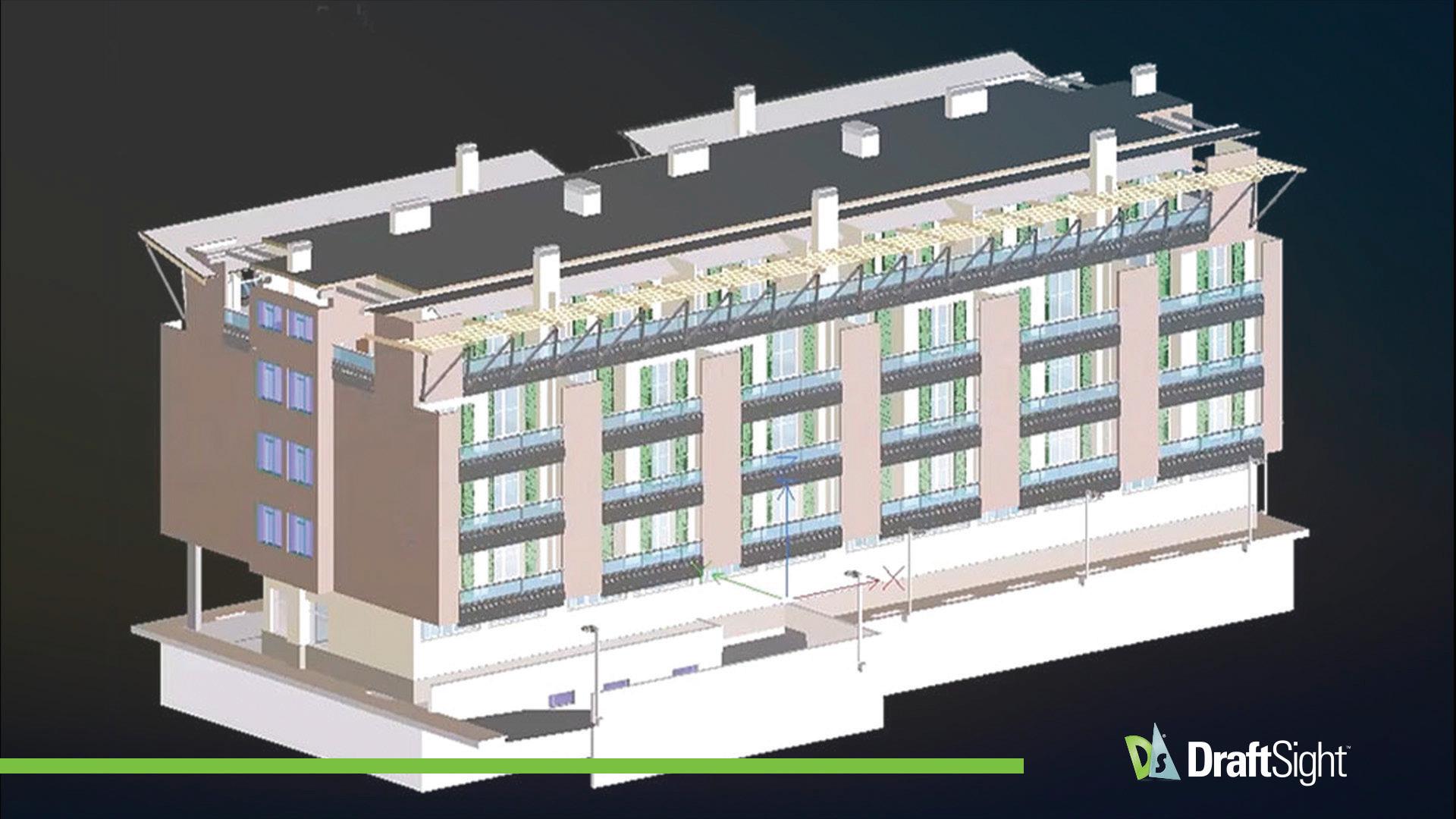
DraftSight Premium’s BIM Module addresses this by allowing teams to work directly with BIM data inside a 2D CAD environment. Revit and IFC files can be imported without rebuilding geometry, and drawings can be generated with structure and levels intact. The result is usable CAD geometry that behaves predictably, reducing the need for cleanup before drafting begins. By referencing underlying model data, annotations, and schedules stay aligned with the source, helping teams maintain accuracy across sheets.
For a limited time, AUGI readers can receive 15% off DraftSight Premium
Reference: Cassandro, J., Mirarchi, C., Gholamzadehmir, M., & Pavan, A. (2025). Advancements and prospects in building information modeling (BIM) for construction: a review. Engineering, Construction and Architectural Management, 32(9), 6006-6026.
Octave BricsCAD V26.2: Sharpen your Edge

The first point-release under the Octave® brand is here, and it arrives with purpose. Octave BricsCAD® V26.2 delivers new and enhanced features designed to make every day CAD workflows faster, more connected and more capable across every discipline. Whether you spend your days in 2D drafting, 3D modeling, BIM coordination, mechanical design or survey, this update addresses the friction points that slow production and the gaps that force workarounds. What makes BricsCAD V26.2 stand out is a coordinated set of improvements that touch general design, documentation, data management and cross-platform collaboration. Many of these
enhancements are available in BricsCAD Pro® and BricsCAD Ultimate®, which also include BIM, Mechanical and Survey workflows. The result is a release that scales across teams and disciplines, meeting users where they work and giving them tools that make a noticeable difference, giving you an edge on your competitors.
BRICSCAD ASSIST: AI-DRIVEN GUIDANCE WITHOUT LEAVING YOUR DRAWING
At the center of V26.2 is BricsCAD AI-Assist, a new AI-driven panel built directly into the interface. Assist helps you find documentation, how-to guidance and answers to workflow
questions without switching to a browser or searching through help files. (See Fig. 1) You stay in your drawing, ask a question and get relevant information on the spot.
For users evaluating BricsCAD for the first time, AI-Assist acts as a built-in coach that reduces the learning curve. For experienced users, it surfaces lesser-known commands and options that can
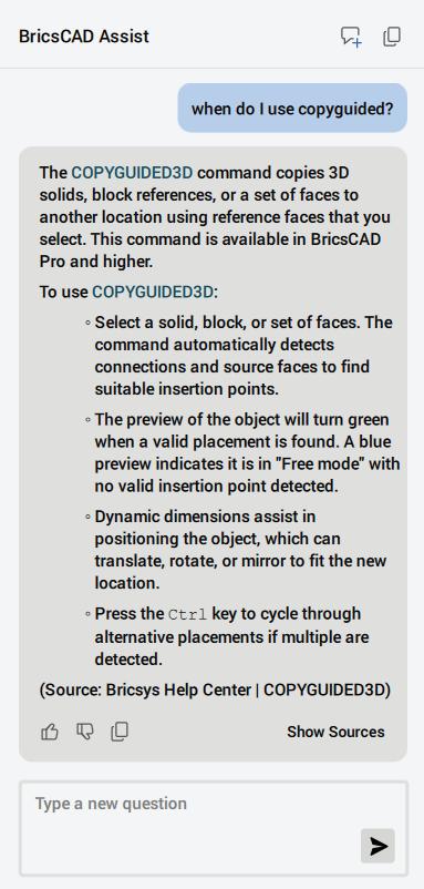
cut steps out of routine tasks. (See Fig. 2) Either way, it reduces context switching and keeps you productive. Think of it as a knowledgeable colleague sitting next to you, ready to help whenever you need it.
To see more of the AI-driven automation tools in BricsCAD, check out https://www.bricscad.com/aidriven-tools

Figure 1
Figure 2
BricsCAD
GENERAL DESIGN AND CORE CAD IMPROVEMENTS
V26.2 focuses heavily on the workflows that every CAD user touches daily. These are not flashy features, but they remove friction in ways that compound over a full workday.
Drawing and documentation enhancements: Several targeted improvements address common pain points in drafting and documentation. Edit faster with context menus shown based on the grip and entity type. Enhanced dimension tools give you more control over placement and formatting. BricsCAD’s Drawing Health (DWGHEALTH) continues to evolve, adding the new Health Advisor tool, where you run drawing health in the background on open drawings, all the while helping you maintain clean files with fewer manual steps.
Text, panels, and dialogs now scale more accurately, interface text and graphics in BricsCAD now offer better visibility, and the annotation and layout
improvements make it faster to produce consistent deliverables, especially when working across multiple sheets or coordinating with teams that rely on your output downstream.
These are the kinds of improvements that save minutes per task and hours per week. Individually, they are small. Collectively, they change how your day feels.
BRICSCAD BIM®: DEEPER INTEGRATIONS AND FASTER PERFORMANCE
BricsCAD BIM users will find meaningful upgrades in V26.2, particularly around interoperability and section performance.
Autodesk Construction Cloud (now a part of Autodesk Forma®) and Bentley ProjectWise® integrations: These cloud integrations extend BricsCAD into broader project ecosystems with connections allowing you to stay linked to project data without the export-and-reimport cycle that eats up time and introduces version control risk. Instead of treating BricsCAD as an isolated design environment, these integrations position it as a connected node in the larger project delivery chain. See it in action: https://youtu.be/BricsCAD/ BIM
For teams working in mixedsoftware environments, this is significant. You can now access project files, coordinate with stakeholders on other platforms and maintain continuity across tools, all from within BricsCAD.
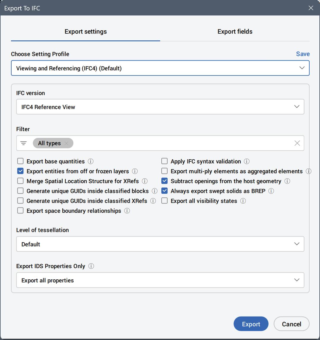
New IFC export dialog: The IFC export workflow gets a significant upgrade with a new dialog that gives you full visibility into what geometry and data are being exported. Filters and user profiles let you control the output precisely, and the interface makes it clear what is included and what is not. For teams collaborating through open BIM workflows, this level of control is essential for maintaining data quality across handoffs. (See Fig. 3)


Faster BIM section performance:
Section generation on large BIM models has historically been a bottleneck. V26.2 introduces performance gains that reduce wait times when generating and updating sections, especially on complex projects with high element counts. Faster sections mean faster documentation cycles and less idle time waiting for the software to catch up with your intent.
BIM data retention across Level of Detail: One of the more subtle but impactful improvements is the way BricsCAD now handles BIM data as you move between Levels of Detail. Previously, transitioning between LOD states could cause data loss or require manual re-entry. V26.2 ensures that BIM properties remain intact across LOD changes, so your data stays consistent from early design through construction documentation.
Match Properties has also been enhanced to copy all BIM properties across different Levels of Detail. This gives you a reliable way to propagate data standards across your model without manual intervention.
BRICSCAD MECHANICAL®: STABILITY, INTEGRATION AND TARGETED FIXES
BricsCAD Mechanical in V26.2 leans into reliability and data management, with a focus on connecting the design environment to the systems that surround it.
Siemens Teamcenter® and Autodesk Vault® integrations: BricsCAD now connects directly to both Siemens Teamcenter (See Fig. 4) and
Autodesk Vault (See Fig. 5), bringing PLM and PDM workflows closer to the design environment. Managing product data, revision control and release processes no longer requires stepping outside BricsCAD. For mechanical teams operating in structured data environments, this integration reduces manual handoffs and keeps design files synchronized with the systems of record.
Local sheet metal repair: Sheet metal parts often require targeted corrections after initial design, especially when tolerances shift or manufacturing feedback arrives. V26.2 introduces local sheet metal repair, SMREPAIR, allowing you to fix specific features without reworking an entire part. This surgical approach saves time and preserves the design intent of the rest of the component. See it in action: https://youtu.be/BricsCAD/SMRepair
Associative title blocks and mechanical data: Title blocks in mechanical drawings often need to reflect properties like material, weight or revision status. V26.2 makes these connections associative, so mechanical data flows directly into your title blocks and updates automatically as the design evolves. The result is fewer manual edits, fewer errors and documentation that stays current with the model.
SURVEY IN BRICSCAD PRO®: SMARTER DATA CAPTURE AND BROADER FORMAT SUPPORT
Survey workflows in V26.2 see a mix of new capabilities and expanded data support that reduce manual processing and connect BricsCAD more tightly to the instruments and software surveyors use in the field.
Figure 4
Figure 5
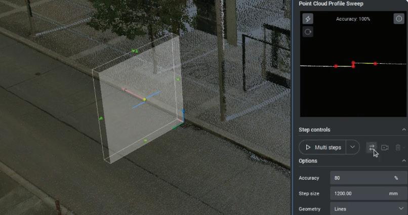
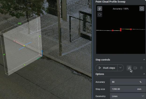
Linear feature detection from point clouds: This is one of the more impactful additions in V26.2. Instead of manually tracing features from scanning data, you can now detect and generate linear features directly from a point cloud. (See Fig. 6) Output options include lines, polylines, civil strings or surfaces. For survey teams processing large scan datasets, this capability compresses what used to be hours of manual work into a more automated and repeatable process.
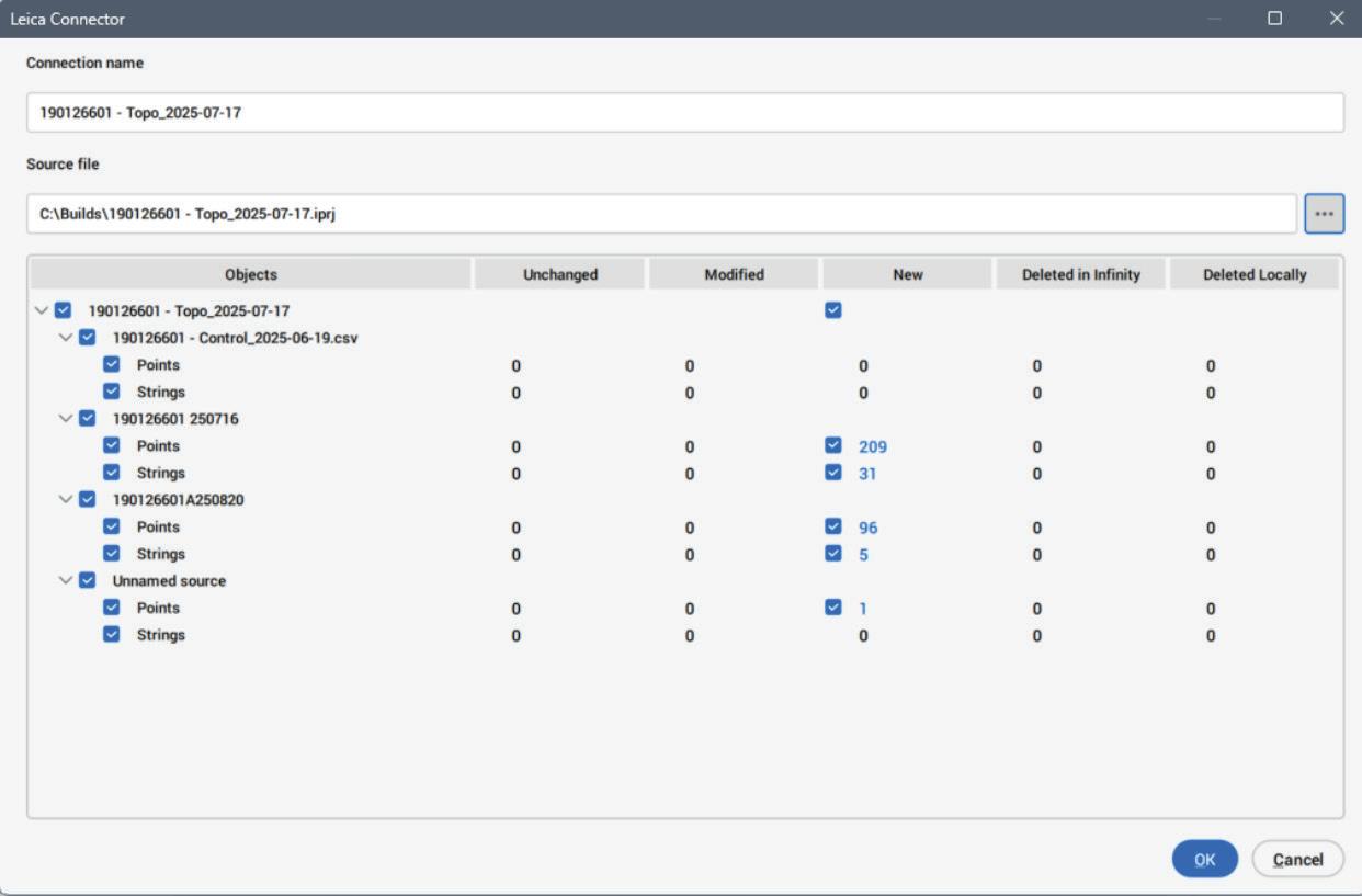
Leica Infinity integration: The new LEICACONNECTOR command provides a direct, live connection to Leica Infinity surveying software. This integration reduces the need for intermediate file exports and imports, giving you a streamlined path from field data collection to CAD production. If your team relies on Leica instruments and workflows, this connection removes a significant friction point. (See Fig. 7)
Digital Elevation Model support: V26.2 expands terrain data handling with the ability to import and export Digital Elevation Models in GEOTIFF and ASCII Grid formats. This gives survey and civil teams more flexibility when exchanging terrain data with GIS platforms and other analysis tools. Whether you are receiving elevation data from external sources or delivering terrain models to project stakeholders, the expanded format support keeps your workflows moving without conversion bottlenecks. See it in
action: https://youtu.be/BricsCAD/Survey
GIS export improvements: The GIS export command gets updated options, a more consistent interface and shared profiles that help standardize output across projects and team members. When your deliverables need to move between CAD and GIS environments, these improvements reduce the setup time and ensure consistent results.
WHY V26.2 MATTERS FOR YOUR TEAM
Releases like V26.2 reflect a development philosophy that prioritizes practical, measurable improvement over spectacle. Every feature in this update addresses a real workflow scenario: the section that took too long to generate, the block library that grew unwieldy, the PLM system that required a separate login, the point cloud that demanded hours of manual tracing.
This release also signals something important about the direction of BricsCAD under the Octave brand. This is a platform that does not force you to choose between disciplines or pay for capabilities you do not use. We will continue to deliver improvements that apply to your daily work and your bottom line. The improvements are not theoretical but designed to help you work faster, cleaner, and with a decisive edge for you and your organization.
Figure 6
ABOUT OCTAVE BRICSCAD®
Octave BricsCAD® is the true CAD alternative. We are the 2D and 3D CAD alternative that helps you switch smoothly, excel in the detail, and realize better value from day one. Download the free, 30day trial of BricsCAD. Would you like free lessons? We have that available at BricsCAD Learning. Ready to migrate to BricsCAD? Download the free Migration Guide. Follow us today on LinkedIn and YouTube.
ABOUT OCTAVE®
Octave® provides enterprise software that helps organizations design, build, operate and protect critical industrial and infrastructure assets. Octave supports decisions across the full asset lifecycle where performance, safety and reliability matter and failure is not an option. Octave connects engineering, operational and safety workflows, enabling customers to convert complex operational data into decisions that improve performance, resilience and incident response across realworld environments. Octave has more than 7,000
employees in 45 countries. Learn more at octave. com and follow us on LinkedIn.

Mr. Craig Swearingen is a Global Implementation Specialist and Customer Success Consultant at Octave BricsCAD. Currently, Craig provides migration and implementation guidance, management strategies, and technical assistance to companies which need an alternative, compatible CAD solution. Craig spent 19 years in the civil engineering world as a technician, Civil 3D & CAD power user, becoming a support-intensive CAD/ IT manager in high-volume production environments. Craig is a longtime AUGI member (2009), a Certified Autodesk® AutoCAD® Professional, and he enjoys networking with other CAD users on social media.
Figure 7
Learning from My Mistakes

We all make mistakes. I have made plenty of them over the years. Some were in my work life; some were in my private life. Some were not a big deal and others had drastic impact. Some were technical blunders and bad calls; others were strained interactions with people. A few of them generated regrets and some were unavoidable (or so I thought at the time). Some were caused by an uncaring midframe, some from an uncontrolled tongue, some from anger, some from forgetfulness, and many from lack of tech awareness, knowledge or experience. One thing that is common to all of them is that I tried to learn from them. Some of them offered immediate lessons (“don’t do that again”) and others took a lot of reflection before coming away with positive changes that were needed.
Here are a few steps that I have taken and still take, when I have done something that was wrong, or not optimal. This article is focused on the efforts I make and so I write in first person mode.
ACKNOWLEDGE THE MISTAKE
I try not to blame others. I take ownership of my part. This is always the first step. I need to admit that there is a problem and identify my part in the issue. It may not be all my fault, but I should take ownership of my contribution to the troubles. If I offended anyone, I need to apologize. I should do that directly with the offended person and keep it brief. I should not bring up deflecting reasons for my failures, just apologize and try not to deflect.
PONDER THE PROBLEM
I think about my mistakes. This is an important step toward learning lessons. There are times when
I did not want to think much about something I did wrong. Who wants to dwell on negatives? But pondering is not ruminating on bad things or beat myself up over it. It is taking an honest look at what happened and how I can avoid it in the future. Some lessons are quick adjustments and changes can be made in the short run. Some are long haul changes that may require me to work on my character or behavior patterns.
THE FIVE WHYS
Developed by Sakichi Toyoda, the Five Whys is a method of getting to the root cause of a problem. Look him up. This man’s story is great. His method can be applied to learning from mistakes as it helps drive analysis down to the thing that needs to be corrected. The way it works (you may already know this), is that you ask “why?” at least five times related to the issue. You probably do this already when troubleshooting tech issues. Digging into root causes is part of your job. I focus on finding details of the problem, not placing blame. There is no magic in the number five. Some issues might only need three whys, others need more.
Here is a real-world example of using five whys that happened with me in the past.
Problem: The plotter is out of paper, and we have no more paper in stock.
Impact: A delay in the output of plots that threatened to impact the deliverable timeline.
1. Why? The stockroom had no more rolls when the last roll on the machine ran out.
2. Why? I forgot to order more before it was needed.
3. Why? I assumed we had more because the storage racks had old, empty boxes on the shelves.
4. Why? I did not remove old, unusable stock.
5. Why? There is no specialized inventory system or “reorder point” specifically for long-lead technical supplies. (Root Cause)
THE SOLUTION
I admitted that I failed to make the order and apologized. I contacted a local provider and did a will call pickup of several rolls immediately (short term fix that addressed the deadline). I implemented a reorder system specifically for the plotter paper (long term fix that avoids future
issues). I worked with the paper provider and set up auto deliveries and had their delivery team checking inventory on our shelves and maintain a minimum shelf count. If we got below the roll count I set as a trigger, they automatically ordered more. After that, we constantly had them checking and restocking when levels got low.
One mistake does not define me. Others may be annoyed by something that happens, but unless my behavior or mistakes are a long-term pattern, an incident of failure does not define who I am. No need to sink into the doldrums because I did not meet other people’s expectations or my own. I try to just address the issue in the short term, apologize, dust myself off and keep going. Then think about what could be done differently the next time.
Learn from other people’s mistakes. This is what I try to do and suggest to others. Don’t I have enough to think about with my own shortcomings? Do I really need to think about other peoples faltering actions? Yes, because if I can learn from what others do not get right, then I might be able to avoid me not getting it right when something similar comes along. This involves me listening to the issues and watching how others handle it. If I do not have to make a mistake myself to have a lesson learned, that is progress. Learning from my mistakes is good. Learning from other people’s mistakes may be even better.

Mark Kiker has more than 30 years of hands-on experience with technology. He is fully versed in every area of management from deployment planning, installation, and configuration to training and strategic planning. As an internationally known speaker and writer, he was a returning speaker at Autodesk University for twenty years. Mark has served as Draftsman, Principal Designer, CAD/BIM Manager, Systems Analyst, IT Director, CTO, CIO and AUGI Board President. He can be reached at mark.kiker@augi. com and would love to hear your questions, comments, perspectives and ideas for future topics.
Is Civil 3D 2027 The Best Version EVER?

It’s always fun to see the new items in all of Autodesk products. Could there be more? Absolutely!! Is 2027 the best version ever? Some say it is, some say it isn’t, but here’s my take on why I’m leaning towards Civil 3D being the BEST VERSION EVER.
Ok, ok…… “Best version ever” may be a stretch— Autodesk releases are iterative, and whether Civil 3D 2027 is best depends heavily on what you do (corridors, pipe networks, survey, etc.). But there are usually a few reasons people might hype a newer version like that:
1. Performance improvements -
Recent versions have been focusing on faster corridor rebuilding, better handling of large surfaces, and less lag with complex drawings. If 2027 continues that trend, users working on big infrastructure models will feel it immediately.
2. Automation and smarter tools
Autodesk has been pushing more automation— things like improved subassembly workflows, better targeting, and possibly more AI-assisted suggestions (e.g., design checks, optimization hints). If those reduce manual edits, that’s a real win.
3. Better interoperability
Each version usually improves compatibility with:
• Revit / InfraWorks workflows
• IFC and open standards
• GIS integrations
If 2027 smooths data exchange further, that’s huge for multidisciplinary teams.
4. UI and usability tweaks
Not flashy, but small improvements—tool organization, clearer dialogs, fewer clicks for common tasks—can add up to real productivity gains.
5. Cloud and collaboration features
Autodesk has been steadily tying Civil 3D into Autodesk Construction Cloud…...oops, I meant FORMA. If 2027 deepens that (live data sharing, version control, etc.), teams working remotely benefit.
But let’s get into some of the new features introduced in AutoCAD and Civil 3D 2027, and you can decide for yourself.
AUTODESK ASSISTANT
By utilizing the innovative Model Context Protocol (MCP), it interprets drawing context and user intent, enabling efficient CAD standards checking. Viewers will learn how this advancement streamlines workflows with enhanced AI chat and prompt-driven capabilities.
Autodesk Assistant now offers AI-enhanced chat and prompt-driven workflows.
Autodesk Assistant includes the following enhancements:
• Ability to check standards of the current drawing against a standards file
• Selection based on natural language prompt
• Ability to query drawing for information, such as layers list, block usage, etc.
• Query and modify the visual styles of Civil 3D objects
• Analyze and stylize Civil 3D surface slope ranges
• Prompt library and chat history
Here’s some example prompts used in a recent file that shows the power behind this new Autodesk Assistant in relation to fairly common tasks within Civil 3D.
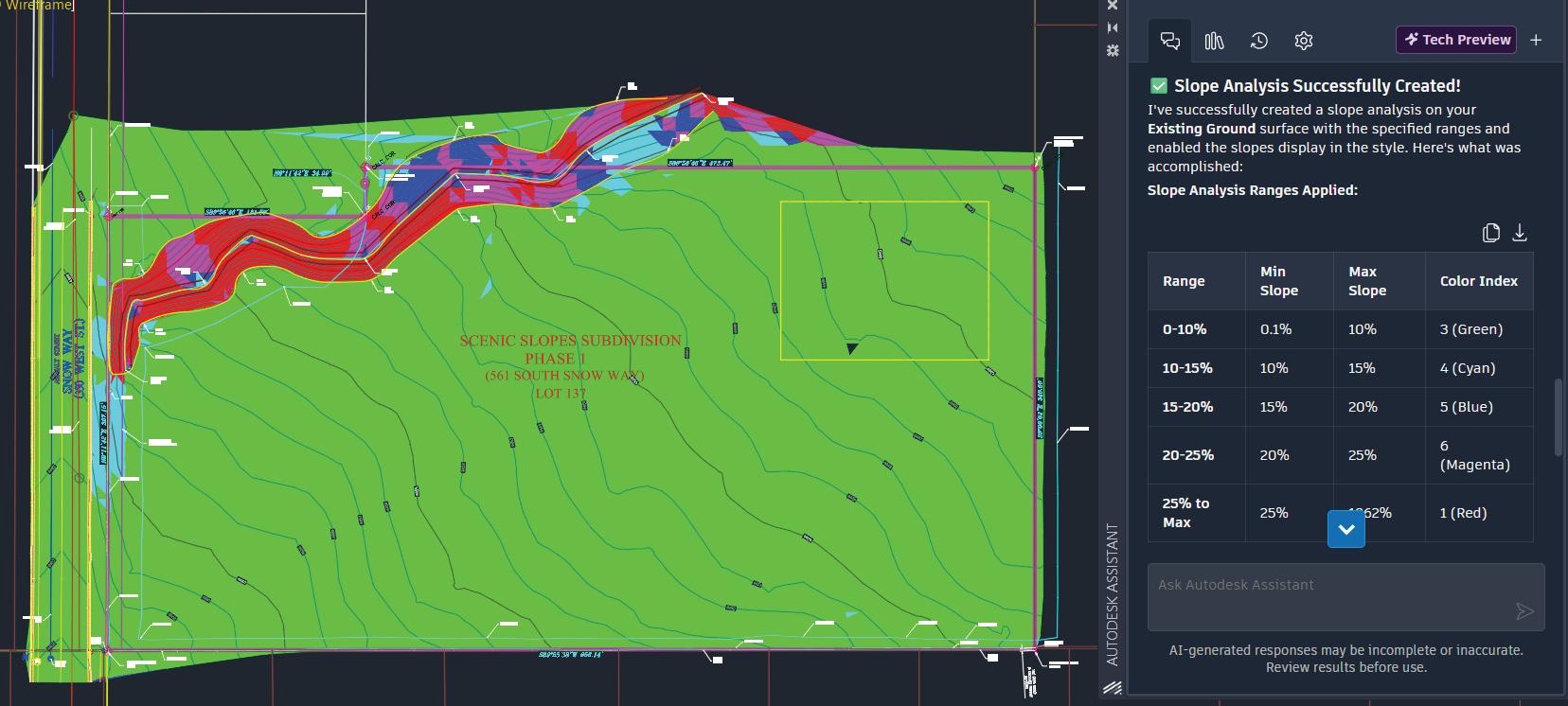
Prompt #1 – “Using the Existing Ground surface, create me a slope analysis with the following ranges, and turn on the slopes in the style. The ranges should be 0-10%, 10-15%, 15-20%, 20-25% and 25% to max slope”
See Figure 1.
Prompt #2 – I have a 2D drawing and I want to know the linear footage of all my road centerlines. They are all polylines and on layer C-Road-Line. “Give me a total length of road centerline for the polylines on layer C-ROAD-LINE”
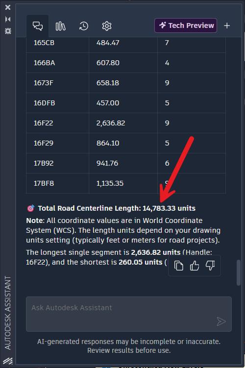
See Figure 2.
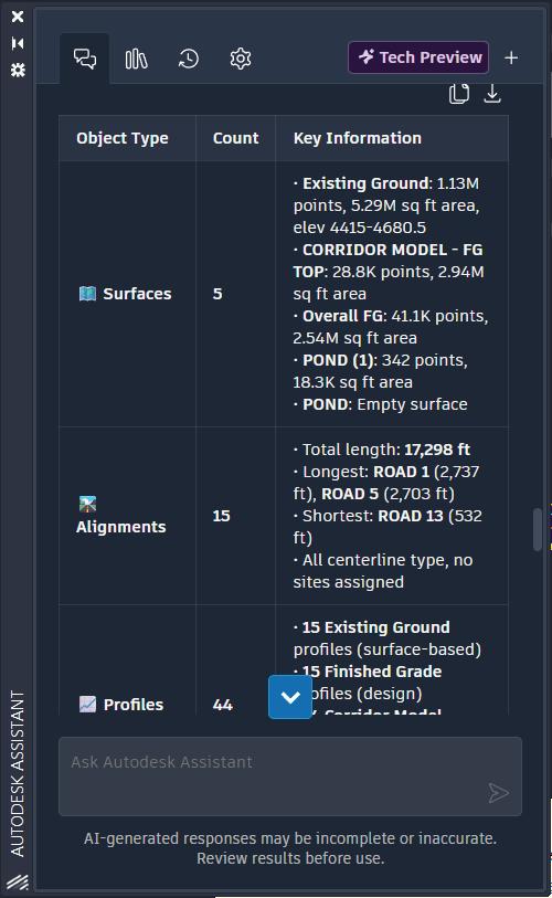
Prompt #3 – This is a default suggestion from the Autodesk Assistant. “Analyze the current Civil 3D drawing and provide a comprehensive inventory of all Civil 3D objects. Create a table with the following columns: Object Type, Count, and Key Information.”
See Figure 3.
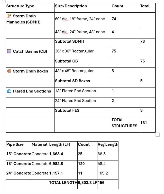
Prompt #4 – And finally, one of the favorites I’ve used lately for quantity takeoff. “Create me a quantity table of the structures (type, size count) and pipes (size and length) of the items within the SD pipe network”
See Figure 4.
AUTOCAD PLATFORM ITEMS
Geometry Cleanup
Geometry Cleanup scans drawings to find common
4
Figure 2
Figure 3
Figure
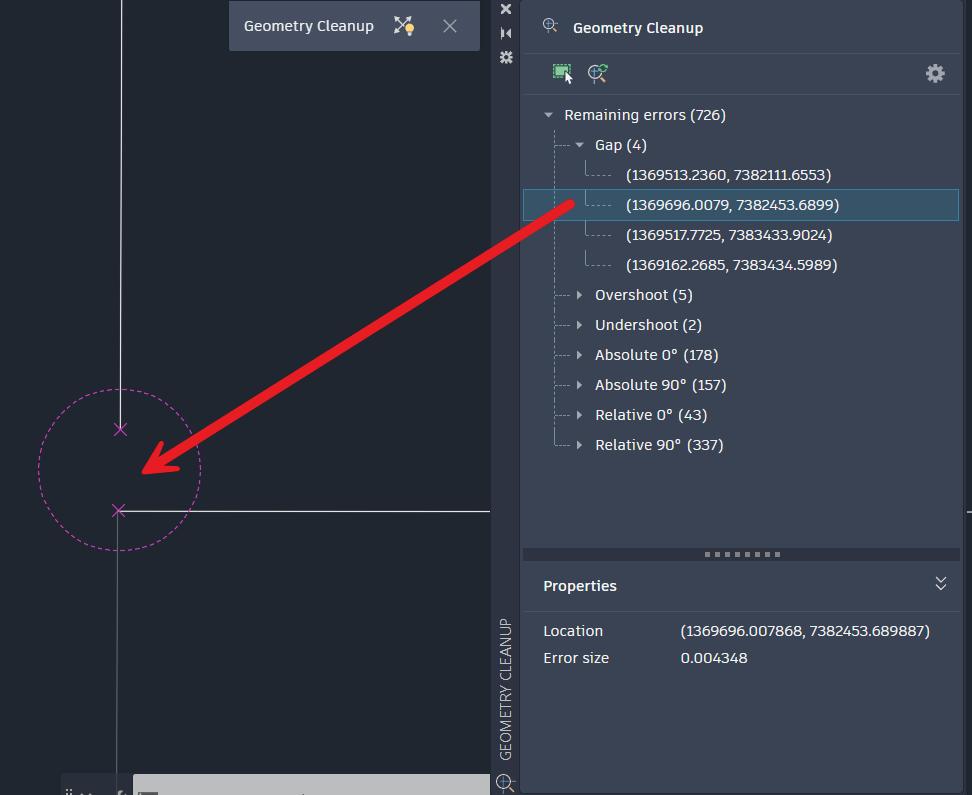
geometry errors including gaps, overshoots, undershoots, and misaligned angles. It highlights errors directly in the drawing window with visual markers.
Additionally, Geometry Cleanup offers several options for each error, allowing you to choose the best fix. You can also choose to ignore suggestions and keep the geometry as designed when needed.
This works great for use cases such as boundary/ deed descriptions and trimming up some rouge drafter lines!
To use Geometry Cleanup, start by opening the palette. You can do this by typing GEOMETRYCLEANUPOPEN at the Command prompt, or from the ribbon, click Manage tab > Cleanup panel > Geometry Cleanup.
See Figure 5.
Checkout the new CHECKOUT tool
Checkout allows a user to edit and propose changes to specific objects in a drawing that someone else has open for editing. Instead of waiting for the drawing to be released by the user who edits, you can check out the objects you want to edit, edit them in the Trace environment, and then submit your changes for review to the user who has readwrite access. The user with read-write access can then merge the changes into the drawing.
Note: Checkout only works with drawings saved in Forma Data Management.
Step 1: One collaborator has a drawing open with read-write access that is saved in Forma Data Management. A second collaborator opens the drawing read-only.
Step 2: The second collaborator starts the CHECKOUT command, then selects and confirms a
Figure 5
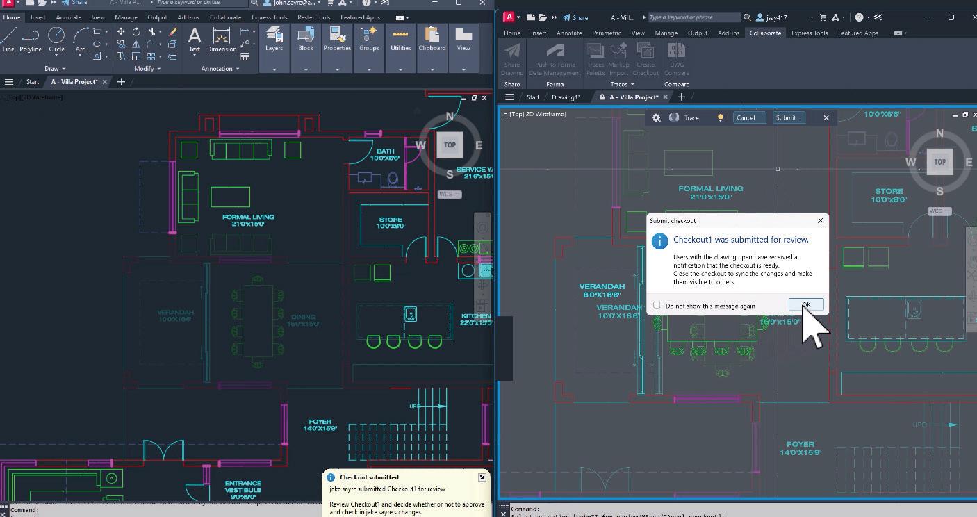
portion of geometry in the drawing to check out. The selected portion of the drawing opens in the Trace workspace in a new trace. The checked-out geometry locks for the collaborator who has the drawing open with read-write access.
Step 3: The second collaborator makes changes to checked out portion of the drawing in the new trace. When they finish editing, they submit and close the trace.
Step 4: The collaborator who has the drawing open with read-write access receives a notification in the drawing that a collaborator has submitted changes. They can then review the changes and decide whether or not to merge them into the drawing.
See Figure 6.
Object Compatibility in Specialized Toolsets
The following technical considerations apply when using the CHECKOUT command in AutoCAD and its specialized toolsets.
• Checkout filters out custom objects created in AutoCAD specialized toolsets, including AutoCAD Architecture, AutoCAD MEP, AutoCAD Mechanical, AutoCAD Map 3D, and AutoCAD Plant 3D.
• The checkout operation excludes custom
toolset objects, and the excluded objects remain unavailable for modification while the drawing is checked out.
• The AutoCAD Electrical toolset does not support Checkout.
New Commands
CHECKOUT - Check out and modify selected geometry in the Trace workspace while a collaborator has the drawing open. When finished, submit your changes for approval.
DAYLIGHT FEATURE LINE
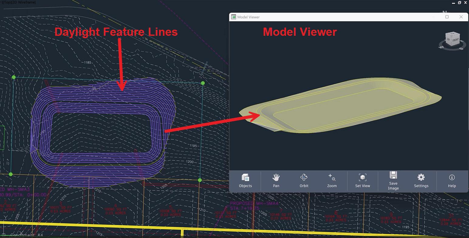
Civil 3D 2027 introduces Daylight Feature Line, a powerful new tool that automates the creation of daylight lines from grading criteria - streamlining your grading workflow.
Automated Daylight Generation
Generate daylight feature lines directly from existing grading criteria. Created feature lines behave as standard feature lines, allowing full editing flexibility with familiar tools.
See Figure 7.
Flexible Command Options
Fine-tune your daylight feature line creation with comprehensive command options:
Figure 6
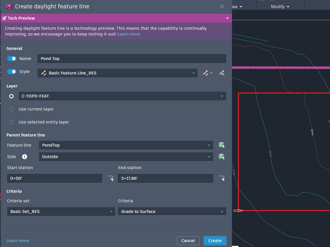
• Grading Criteria - Select from available criteria
• Station Range - Define start and end stations
• Side - Specify the side where the daylight feature line will be located
• Layer - Assign to desired layer
• Name and Style - Apply custom naming and styling
See Figure 8.
Feature Line Stability and Performance
If you use feature lines and grading objects, you know they are about as stable as a 600-pound 1-legged man!! So, attention to this is much needed, and I hope it is just the beginning of the focus on grading tools.
Improved Stability -
Multiple crash scenarios have been addressed, particularly around feature line operations like weed, inserting intermediate points, and undo/redo actions.
Better Performance
-
Siteless feature line edit operations (select, raise/lower, offset, join) are significantly faster due to optimized grading update logic.
Enhanced Undo/Redo Reliability - Undo/redo has always led to corruption in files, it’s about time this gets addressed. Fixed several issues where undo operations caused geometry corruption, elevation point loss, or unexpected UI behavior.
Site Operations
Fix - Moving parcels between sites no longer causes crossing feature lines to disappear.
DRAINAGE DESIGN & ANALYSIS
Autodesk Drainage Tools for Civil 3D are now included and installed beginning with Civil 3D 2026.2. This is a productionready tool set designed to integrate
Figure 7
Figure 8
Civil 3D
the drainage design environment of Civil 3D with analysis capabilities powered by InfoDrainage analysis cloud-services—all without leaving Civil 3D!
Civil 3D enables an integrated workflow for designing and analyzing storm drainage systems. With analysis capabilities powered by InfoDrainage, you can run storm event simulations, evaluate system performance, and apply results directly to your model to support informed decision-making.
You can use the Rainfall Manager to specify pre-defined or custom rainfall events, perform preliminary system checks, and analyze multiple scenarios to identify issues and refine designs.
Civil 3D 2027 continues to enhance these workflows with expanded capabilities:
• Catchment: Added support for FAA and Kirpich time of concentration methods.
• Channels: Streamlined support for multiple slopes within a single channel.
• Gravity Pipes: Improved Pipe Network Vista, enhanced labeling, and added support for arch, elliptical, and egg-shaped pipes in the analysis.
• Ponds: New Porosity option to define available storage capacity.
• Underground Storage: Expanded connectivity with pipes and drainage objects, with improved integration as a standardized Civil 3D object.
Additional improvements support data interoperability and collaboration across teams using different versions of Civil 3D with Data Shortcuts. And updates to pipe and pressure pipe catalogs support both local and cloud-based workflows through Autodesk Forma Data Management. These updates improve shared access, enable centralized management, and support automatic synchronization across project teams.
HORIZONTAL REGRESSION ANALYSIS
Horizontal Regression Analysis helps you generate smooth horizontal alignments for projects using existing survey data. Civil 3D analyzes measured points along an existing path and calculates tangents, curves, and transition spirals that best fit the surveyed conditions.
Using the Horizontal Regression Analysis Vista, you can review regression-generated alignments and refine results using tools for de-noising data, adjusting spiral sensitivity, and defining the
maximum acceptable curve radius. Once optimized, the results can be used to create new alignment geometry for railways, roads, highways, and pipelines with minimal deviation from real-world conditions.
However, I wonder what the major difference is between this and a simple best fit analysis alignment?
For example, I used this fancy new HRA tool as well as the old reliable Best Fit tool on the same set of road centerline points.
See Figure 9.
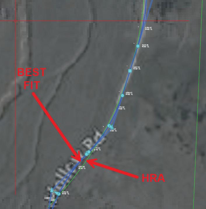
Figure 9
Forma Data Management Essentials
AutoCAD and Civil 3D subscriptions now include Forma Data Management Essentials. It provides a central source for project information, helping your team stay connected.
Key features are:
• Online drawing file collaboration
• Permission-controlled access
• File versioning
• File sharing
• File review tools
CONNECTED REFERENCES & SUPPORT FILES
Connected References improves the workflow for updating the paths of missing external drawing references (xrefs).
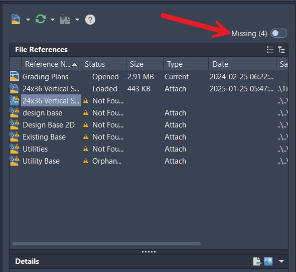
When working with drawings that contain references, the new Missing toggle allows you to switch to the Missing References view in the File References pane. This view exclusively shows missing external drawing reference (xref) files.
See Figure 10.
From the Missing References view, you can perform the following tasks on selected missing references:
• Detach references that are no longer needed
• Update the paths of references by browsing and specifying a new path
• Resolve the paths of references based on suggested paths (applies to drawings opened from an Autodesk project only)
• Suggested Path for References
Normally, when a referenced file is renamed or moved, any drawing that depends on it can no longer locate it because its path has changed. As a result, you must update the path for each missing reference to load it properly into AutoCAD.
See Figure 11.
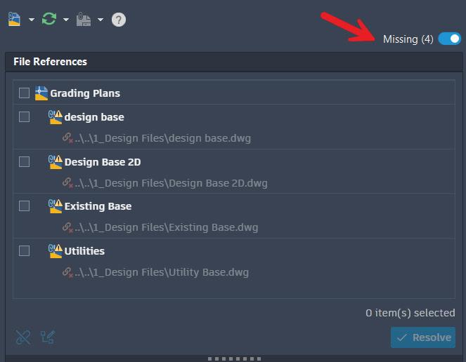
With Connected References and referenced drawing (xref) files stored on Forma Data Management, the External References palette automatically attempts to locate missing reference files that have been renamed or moved. When a missing reference file is found, a suggested path is displayed, which you can accept to avoid manually updating each missing reference.
Connected Support Files: Tool Palettes
Tool palette and authoring palette files can be shared with others working on the same Autodesk project stored on Forma Data Management.
When configuring an Autodesk project on Forma Data Management, you can specify the locations for the project’s tool palette and authoring palette files.
Note: Connected Support Files are now available in Forma Data Management and ACC Library.
If you are new to tool palettes and authoring palettes, the following provides a brief description of each:
• Tool palettes: Provide access to project-related blocks, hatch patterns, custom commands, and many other tools that help enforce CAD standards. When loaded, these palettes appear on the Tool Palettes window.
• Authoring palettes: Provide tools for creating and modifying dynamic blocks. When loaded, these palettes appear on the Block Authoring Palettes window within the Block Editor.
Figure 10
Figure 11
Civil 3D
Configure Tool Palettes and Authoring Palettes for an Autodesk Project
After Connected Support Files have been set up for an Autodesk project, follow these steps to configure tool palettes and authoring palettes for the project:
Important: Only project members with Project Administrator access can configure Connected Support Files.
• Upload your project-related tool palette (ATC) files to the Autodesk project.
• In AutoCAD, open a drawing from the Autodesk project of which you want to configure tool palettes and authoring palettes.
• In the drawing area, right-click and choose Options.
• In the Options dialog box, click the Files tab and expand the Project Settings node.
• Expand Tool Palettes File Locations and then click Add a Location under the node.
• In the Browse for Folder dialog box, browse to and select the folder containing the uploaded tool palette files, and then click Open.
• If you uploaded authoring palettes, repeat steps
5 and 6 for the Authoring Palette File Locations setting.
• Click OK to save the changes.
Pushing Sheets to Forma Data Management
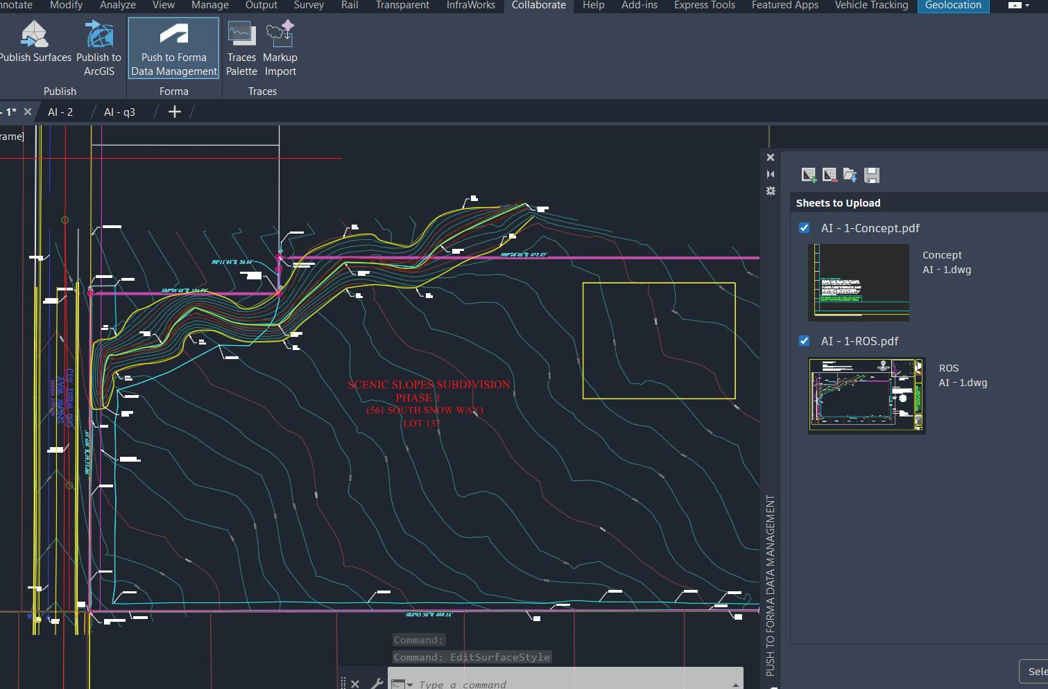
Push to Forma Data Management allows teams to view digital PDFs in the field for reference. Use Push to Forma Data Management to upload layouts from multiple drawings and upload them as PDFs to a selected project folder on Forma.
Important: Push to Forma Data Management is a feature available to subscribers only.
The Push to Forma Data Management feature is available with the 2022 and later releases of AutoCAD, AutoCAD LT, AutoCAD specialized toolsets, and Autodesk Civil 3D products.
Click Collaborate tab > Forma > Push to Forma Data Management. You can also enter PUSHTOFORMAOPEN at the command prompt.
See Figure 12.
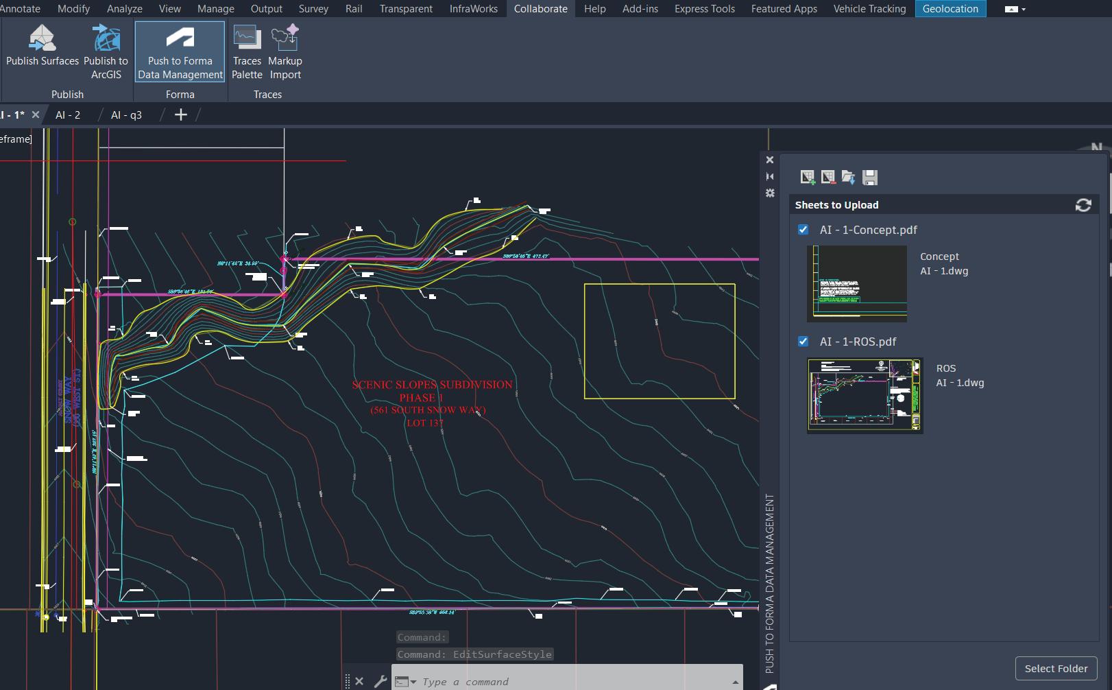
The Push to Forma Data Management palette opens. By default, all layouts for the current drawing are added to the palette and are selected.
Create a list of layouts available to upload to Forma Data Management using these icons:
• select a drawing to add the layouts to the list of available sheets
• remove the selected layouts from the list of sheets
• load a previously saved list of sheets
• save the current list of sheets to a file for easy retrieval
Select or clear the check boxes to define which sheets you want to upload as PDFs to Forma Data Management.
Click Select Folder.
Select the project from the drop-down menu that you want to upload the AutoCAD drawings as PDFs too. Navigate to and select the folder within project.
Single click a folder name to select a folder for upload.
Indicates the folder contains sub-folders. Doubleclick to see a list of its sub-folders.
Double-click to go back one folder level.
Click OK.
PDFs are created for the selected layouts and uploaded to the selected project and folder. Click the link on the Push to Forma Data Management palette to open a browser at the cloud location.
Note: PDFs are published and uploaded in the background so may not be immediately available in the cloud.
CIVIL 3D 2026 & 2027 – MODEL VIEWER
I love this! I know this was new in 2026, but I still see most people using that old school object viewer!! Model Viewer facilitates high-performance and isolated 3D review of selected objects within the Civil 3D environment.
Open the viewer, select objects, and freely navigate those elements of your drawing, all in a separate
window while still being able to access your project data, unlike Object Viewer.
You can now review complex objects such as corridors and subassemblies in a new way that provides better insight without detracting from regular workflows.
Ever have a spike or a hole in a surface and wonder what’s going on? Or maybe crossing pipes you want to visually inspect for interference checks? Before, you’d have to select the objects, and go to object viewer, and if you forgot to select one thing, you’d have to do it over again.
See Figure 13.
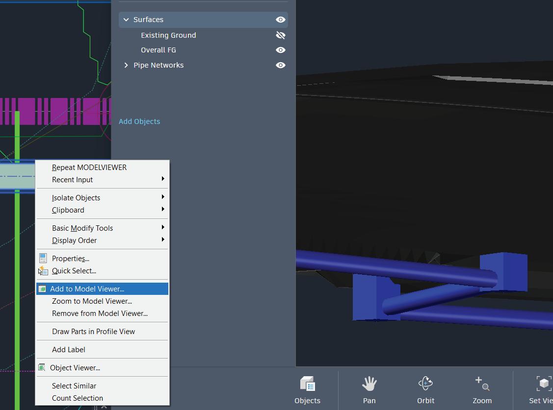
To open the Civil 3D Model Viewer, you must first add or zoom objects to the viewer.
1. Select an object in Prospector or in canvas.
2. Right-click the object after selection.
3. Select Add to Model Viewer or Zoom to Model Viewer from the context menu.
This will open the Model Viewer. To add more objects to the viewer, simply select additional objects and choose Add to Model Viewer. There are 4 sections of the Model Viewer Panel:
1. Objects Panel. Lists the selected objects for the Model Viewer and specifies their visibility. The panel is displayed or hidden by clicking Objects in the Viewer Toolbar.
2. Viewer 3D Canvas. Displays your drawing as a model in this space. Hide or Display specific objects in the Objects Panel and navigate
Figure 13
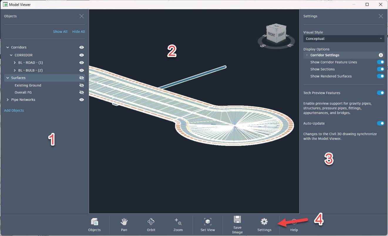
perspective from the Viewer Toolbar.
3. Settings Panel. Supplies visual display styles and other Civil 3D Model Viewer settings. The panel is displayed or hidden by clicking Settings in the Viewer Toolbar.
4. Viewer Toolbar. Enables navigation and perspective views in the 3D Canvas. You can pan, orbit, zoom, and take screenshots of the current view.
See Figure 14.
NOTE: I always turn off my Hardware Accelerator. However, if you intend on using the new Model Viewer, this needs to be on. Type in GRAPHICSCONFIG to toggle this on or off.
MISC STUFF YOU MAY WANT TO KNOW… Bridges in Prospector
In previous versions of Civil 3D, imported bridges from InfraWorks appeared as a single object in the prospector. Now when you import a bridge created in InfraWorks, it will be expandable from the prospector menu. All bridge components will be displayed.
MrSID support
Beginning with Civil 3D 2027, MrSID is no longer supported.
File Format
• Autodesk Civil 3D 2027 uses the AutoCAD 2018 drawing format.
• Drawings saved in Autodesk Civil 3D 2027 can be opened in Autodesk Civil 3D versions 2019 through 2023, and AutoCAD Civil 3D 2018.
CONCLUSION
So, best version ever? I’ll let you decide for yourself!!

Shawn has been a part of the design engineering community for roughly 20 years in all aspects of design, construction and software implementations. He has implemented and trained companies across the Country on Civil 3D and other infrastructure tools and their best practice workflows. Shawn can be reached for comments or questions at sherring@ prosoftnet.com.
Figure 14





What’s New in Autodesk Revit 2027
(That Actually Matters)
Every year, a new version of Revit drops and the cycle repeats. The feature list gets shared, a few highlights get attention, and for a brief moment it feels like something significant has changed. Then projects keep moving, deadlines stay tight, and most teams fall right back into the same habits they had before the upgrade.
That is not a criticism of the software. It is just how BIM works in the real world. New features do not automatically change behavior. They add capability, but they do not fix execution. That gap is where most coordination problems still live.
Revit 2027 does not try to reinvent anything, and that is probably the right call. Instead, it continues a shift that has been building over the last few releases by focusing less on isolated features and more on reducing friction. What makes this release worth paying attention to is not one big headline tool, but a collection of updates that start to tighten the connection between modeling, coordination, and decision-making.
One of the more meaningful additions is Integrated Issues Management directly inside Revit. Issues can now be created and tracked in 3D published views, and they connect into workflows that extend beyond the model, including coordination through Forma. That may not sound groundbreaking, but it addresses a very real gap. Too many teams are still managing coordination issues outside of the model using screenshots, emails, or separate tracking tools. That disconnect is where things fall through. Bringing issues into the model does not fix accountability or ownership, but it does remove one of the easiest ways for coordination to break down. The distance between identifying a problem and acting on it gets smaller, and that matters more than most teams realize.
Performance
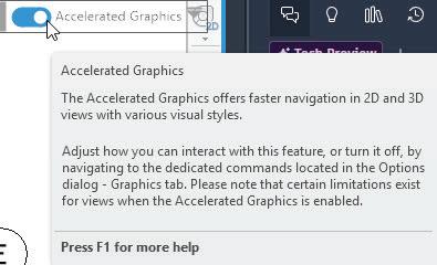
is another area where Revit 2027 quietly delivers. Accelerated Graphics, which has been evolving over the last few versions, is now a more complete and usable part of the workflow. The addition of real-time section box manipulation, driven by the GPU, is one of those improvements that immediately changes how the model feels. Being able to cut through a model instantly, with linked models updating in real time, removes one of those small but constant frustrations that has always slowed coordination down. It is not just about speed. It is about interaction. When it is easier to explore the model, people explore more. When they explore more, they catch more. That is where coordination improves, not because of a feature, but because behavior changes.
Revit 2027 also introduces Autodesk Assistant inside the product as a tech preview, bringing AI-driven support directly into the modeling environment. It can answer questions, help locate information, and even assist with generating content like schedules. There is real value there, especially in reducing the time spent searching for answers or setting up repetitive tasks. At the same time, it is important to stay grounded. AI is not going to fix bad standards, and it is not going

Figure 2: Accelerated Graphics
to clean up inconsistent modeling practices. It will, however, make it easier to move faster. Whether that results in better outcomes or faster mistakes depends entirely on the team using it.
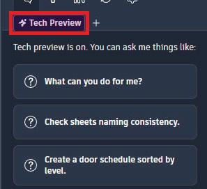
Closely tied to that is the introduction of the Revit Public MCP Server (Tech Preview), and this is where things start to get more interesting. MCP, or Model Context Protocol, allows AI tools to securely connect to external data sources, APIs, and the Revit model itself through Autodesk Assistant. In practical terms, this means you are no longer just asking questions about Revit. You are starting to interact with your model through AI in a more direct and structured way.
That shift is worth paying attention to. With MCP, users can begin to interrogate the model, pull information like element data and counts, check parameters, and even perform bulk edits or generate snapshots through an AI-driven interface. That is a different level of interaction than simply looking something up or running a schedule manually. It moves toward using the model as a querriable data source, not just a graphical representation.
consistent parameters, or clear modeling practices. In fact, it does the opposite. The more you rely on tools like this, the more important it becomes that your data is clean and predictable.
This is where the conversation needs to stay grounded. MCP is not magic. It is an interface layer that makes it easier to access and manipulate the information that is already in your model. If that information is inconsistent, incomplete, or poorly structured, the results will reflect that. If the model is well-built and standardized, the value of something like MCP increases significantly.
That is the real takeaway. Features like Autodesk Assistant and MCP are not about replacing BIM workflows. They are about exposing them. They make it easier to see what is working, what is not, and where the gaps actually are.
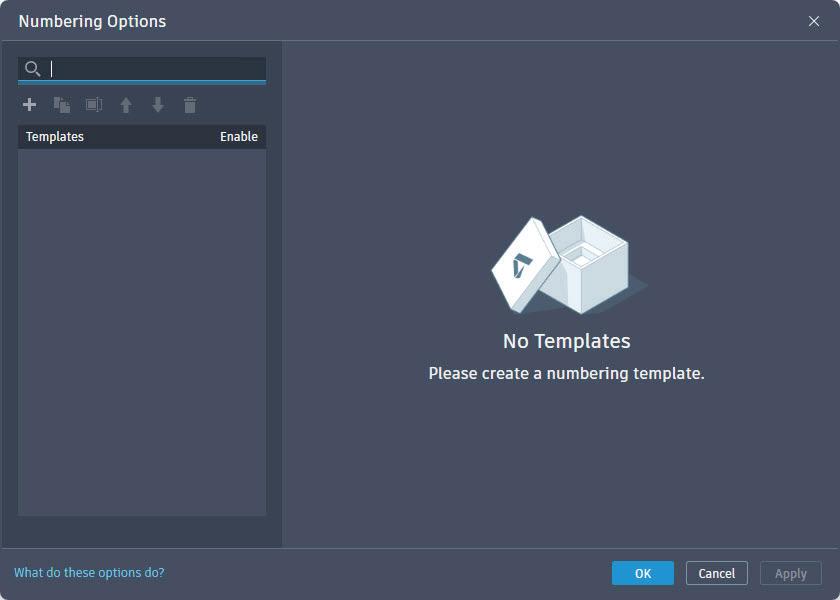
Some of the most useful updates in this release are the ones that will not get much attention. RuleBased Numbering for model elements is a perfect example. Automating numbering through rules, filters, and defined logic is not flashy, but anyone who has dealt with late-stage renumbering knows how quickly that turns into a mess. Giving teams a way to standardize that process removes a lot of unnecessary rework and helps keep documentation aligned with the model as it evolves.
At the same time, this is still a tech preview, and it should be treated that way. There is a big difference between what is possible and what is practical on a live project. MCP is not going to replace established workflows overnight, and it is not going to eliminate the need for structured data,
That same idea carries into the updates around documentation. Improvements to Tag Leader behavior, Multi-Category Tag enhancements, and more consistent control over annotation all
Figure 3: Autodesk Assistant
Figure 4: Rule-Based Numbering
contribute to clearer communication. There are also updates to core dialogs like Synchronize with Central and Worksharing that make the interface feel more consistent and easier to navigate. None of these changes will stand out on their own, but together they improve how information is delivered. Coordination does not stop in the model. It shows up in the sheets, the schedules, and the tags. When those are inconsistent, they create the same level of confusion as a modeling error.
Revit 2027 also continues to push further into a more connected data environment. Features like Extended Properties allow external data, through Autodesk’s AEC data model, to be associated directly with Revit elements in cloud models. Combined with tighter integration across Autodesk platforms, including Forma, this points to a larger shift in how Revit is positioned. It is no longer just a model authoring tool. It is becoming one part of a broader data ecosystem. That opens opportunities, but it also raises the stakes. If the underlying data and standards are not solid, connecting more systems to the model is not going to help. It will just make the problems more visible, faster.
For MEP teams, the impact of Revit 2027 is less about brand new tools and more about improved consistency across workflows. Enhancements to Energy Modeling, including cleaner analytical geometry and more guided setup, help reduce the amount of manual cleanup that used to be required before analysis could even begin. HVAC workflows are also continuing to move toward more system-based logic, tying zoning, loads, and equipment together more consistently. On the fabrication side, the push toward more datarich elements and stronger parameter support continues to improve alignment between design and downstream detailing. None of these changes replace coordination or standards, but they do make it easier to execute both without constantly working around the software.
Revit 2027 is a better version of Revit. There is no question about that. But it does not solve the problems most teams actually struggle with. It does not define ownership. It does not enforce standards.
It does not stop teams from using coordination meetings as a place to discover problems instead of preventing them.
What it does is remove friction in a lot of places that used to slow teams down, create gaps, and make mistakes. For teams that already have structure in place, those improvements will feel meaningful. For teams that do not, the experience will likely feel the same as it always has.
The software continues to improve. The question, as always, is whether the way we use it will improve with it.

Jason Peckovitch is an AUGI Advisory Board Member, Autodesk Certified Professional in BIM Management for Building Design, and Revit Certified Professional for Mechanical and Electrical Design based in SE Iowa. He currently serves as BIM/VDC Manager at ACI Mechanical Inc., bringing over 25 years of CAD/BIM experience and nearly two decades focused on MEP coordination, Revit standards, and scalable content strategies. Jason writes regularly for AUGIWORLD and shares
Weekly BIM Mastery insights on LinkedIn, focused on practical, field-tested BIM without the fluff. He is the author of Becoming a BIM Manager: Industry Insights, Field-Tested Playbook, and BIM Without the Bullshit, a practical guide grounded in real-world implementation, leadership challenges, and what actually works in production environments.
Outside of work, he is a father of three, a published photographer, and a car and tech enthusiast. Connect with him on LinkedIn, find him on X as ThatBIMGuy, or reach out at thatbimguy@gmail.com
Figure 5: Analysis

AutoCAD Architecture 2026 Working with Roofs in ACA
Roofs are AEC objects that you can use to model an entire multiple-face roof surface. You can create roofs independently of other objects or you can place a roof on a shape defined by a polyline or by a closed set of walls. After creating the roof, you can change its overall dimensions and slope or edit its edges and faces individually. For more flexibility in customizing a roof, you can convert it to a collection of individual roof slabs.
A roof slab models a single face of a roof. Roof slab objects also differ from roof objects in that each roof slab is a separate entity with no direct connection to other entities. When you use multiple roof slabs to model an entire roof surface, you have more flexibility in editing the roof, but the combined topology (3D geometry) of the roof is not calculated automatically. For this reason, it is recommended that when you design complex roofs, you start with a roof object. Then, when the design is substantially complete, but you need more flexibility for customizing edges and other details, you can convert the roof into individual roof slabs. While the roof slabs do not dynamically interact with each other, they do allow significant control over the roof geometry. For example, you can trim roof slabs individually, extend them and meter them with other roof slabs. You can also cut holes in roof slabs, add or subtract mass elements, and apply detailed fascia and soffit profiles to any edge at any angle and orientation. Because roof slabs are style-based, you can apply design changes globally.
You can assign materials to a roof. Materials are displayed in wireframe and working shade views or when rendered. Materials have specific settings for the physical components of a roof such as slab. AutoCAD Architecture provides predefined materials for common design purposes. These materials contain settings for roof components. You can use the predefined materials as they are or modify them for your designs. You can also create
your own materials. Object styles provided with the software have appropriate materials already assigned to them.
SLABS AND ROOF SLABS
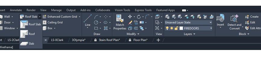
Slabs and roof slabs are AutoCAD Architecture objects that you use to model floors, roof faces and other flat surfaces where edge conditions need to be specified. They are found on the Build panel on the Home ribbon (see Figure 1). The slab or roof slab object is a three-dimensional (3D) body bounded by a planar polygon (perimeter) of any shape and has multiple edges. The object is defined by its perimeter, edge conditions and style. Though they share many of the same properties, slabs and roof slabs represent separate style categories and tool types. For instance, you cannot apply the properties of a slab tool to an existing roof slab object.
Using slab and roof slab tools, you can create slabs and roof slabs independently or you can create them from existing objects such as walls and polylines. Slabs and roof slabs created from other objects do not maintain a link to the original object. Pitched roofs are usually designed by specifying a plate line and a slope angle. Roof slabs are designed so you can use the same approach in laying them out. To add a roof slab, you simply specify two points and an angle. If you have a traditionally designed roof created from a twodimensional(2D) plan showing ridge, hip and valley lines, you can trace over that plan with roof slabs, specifying the desired height and slope. From these values and the specified points, the software creates the correct 3D model.
You can customize each slab or roof slab edge individually, applying styles and making other adjustments as required by your design. A slab or roof slab edge style defines the fascia and soffit design from profiles that you create for these components. You can specify whether the style uses fascia, a soffit, both or neither. You also specify
AutoCAD Architecture
how the fascia and soffit are positioned relative to the slab or roof slab.
Slabs and roof slabs have their own distinct style categories in which individual styles specify the default properties for specific types of slabs or roof slabs. These properties include dimensions, edge styles for the fascia and soffit, and entity properties for layer, color and linetype. Slab and roof slab styles allow you to use a different edge style for each edge. You can assign materials to a slab or roof slab. For example, a floor slab can be assigned to a material representing tiles with concrete edges. These materials are displayed in wireframe or rendered views. Materials have specific settings for individual components of slabs or roof slabs such as the body, fascia and soffit.
In addition to the control provided by slab or roof slab styles and edge styles, AutoCAD Architecture
includes a variety of tools for editing slabs and roof slabs to fit unique conditions. For example, you can add holes to slabs for structures such as chimneys and vent pipes. You can also use roof slabs to create dormers.
SLAB AND ROOF SLAB STYLES
A slab or roof slab style is a set of parameters that determines the appearance and other characteristics of the slab or roof slab object to which it is assigned. By editing a style, you can control the properties of all objects that use that style, without having to change the properties of each object in a drawing. For slabs and roof slabs, the style controls the following properties:
• Default dimensions, including thickness
• Default display properties, including fascia and soffit
• Default edge conditions, including fascia and
soffit styles
• Physical components (concrete, metal deck, etc)
• Materials assigned to components of slabs
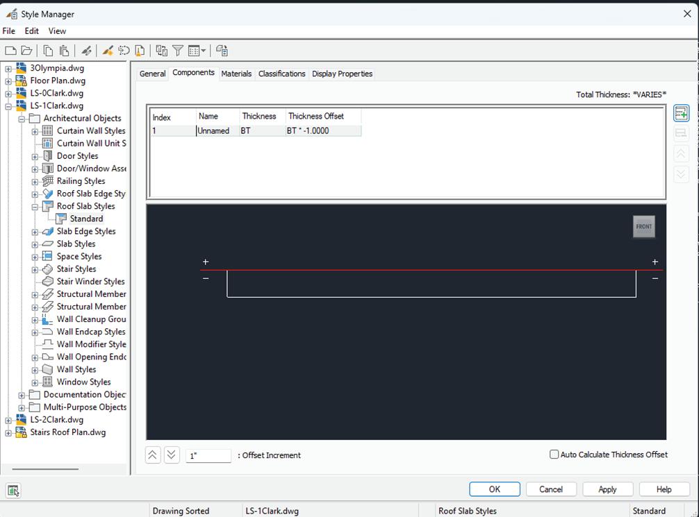
The default slab and roof slab tools provided with the software use standard styles (see Figure 2). You can use these as provided, edit the standard styles in the Style Manager, or create your own styles and use them to make new tools.
You can create a slab or roof slab tool from a slab or roof slab style by dragging the style from the Style Manager onto a tool palette. The default settings provided by the style are then applied to any object created with that tool.
To create, copy, edit or purge styles for slabs and roof slabs, you use the Style Manager. The Style Manager provides a central location in AutoCAD Architecture where you can work with styles from multiple drawings and templates.
EDITING SLABS AND ROOF SLABS
After placing a slab or roof slab object, you can change its style, location, size, slope, shape, edge styles and other characteristics. You can miter its edges and trim or extend it using another object
as a reference. You can also modify slabs and roof slabs using other objects as interference conditions or body modifiers.
Depending on the type of editing you want to perform, various methods may be available:
• After selecting a slab or roof slab, you can click any non-grip point along the perimeter and drag the entire object to a new location. You can also move the object by clicking a grip, pressing the space bar, and then moving the object to the new location and clicking again.
• For grip edits where you are changing a dimension or an angle, the Dynamic Input feature lets you enter a precise value instead of dragging a grip. (This feature is activated by default).
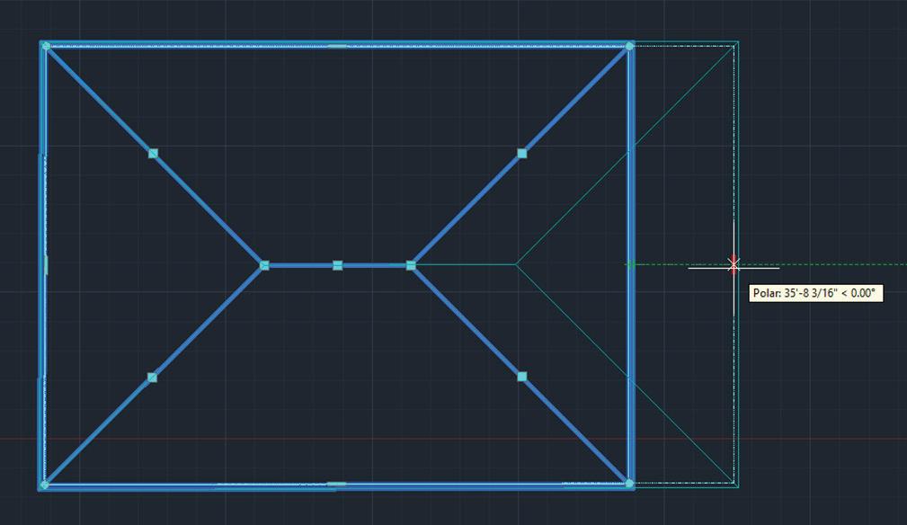
• You can drag the grips that are displayed on a selected slab or roof slab to reorient it, resize it, or change other physical characteristics (see Figure 3).
• You can apply the properties of a slab tool to an existing slab or the properties of a roof slab tool to an existing roof slab.
AutoCAD Architecture
• You can use editing commands from the object’s contextual ribbon tab.
• You can change settings on the object’s Properties palette. You can also use the Display tab of the Properties palette to change the display property settings for a selected object display component in the current display representation.
CREATE A ROOF TOOL
You may want to create your own roof tools if you are placing multiple roofs that have the same properties. For example, say you are creating an office building that has a multi-peaked roof. Although the entire roof is single sloped, each peak has a different slope. To work efficiently, you can create a roof tool for each slope and select the appropriate tool to place the roofs with the correct slope on each area of the building.
Open the tool palette where you want to create a tool. If you want to create a tool from a roof in the drawing, then select the object and drag it to the tool palette. If you want to copy a tool in the current tool palette, then right-click the tool and click Copy. Right-click and click Paste. If you want to copy a tool from another tool palette, then open the other tool palette, right-click the tool and click Copy. Reopen the palette where you want to add the tool, right-click and click Paste. If you want to copy a tool from the Content Browser, then click the Home tab, build panel, Tools drop-down, Content Browser and locate the tool you want to copy. Position the cursor over the i-drop handle and drag the tool to the tool palette.
Now right-click the new tool and click Properties (see Figure 4). Enter a name for the tool. Click the setting for Description, enter a description of the tool and click OK. Expand Basic and expand General. Click the setting for Description, enter a description of the roof created from this tool and click OK. Specify a layer key and any layer key overrides if you do not want to use the layer assignments specified in the layer key style used in the drawing. Specify roof settings. Expand Dimensions and enter a value for Thickness and select a new setting for Edge cut. Expand Next Edge, select a new setting for Shape and enter a value for Overhang. Expand Lower Slope and enter a value for Plate Height. Expand Upper Slope and enter a value for Upper Height. Expand Lower
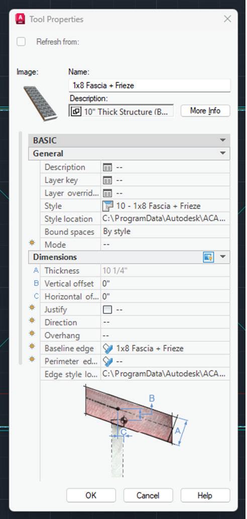
Slope or Upper Slope for a double slope roof and enter a value for Rise or Slope. Click OK.
CREATE A ROOF
You can create a single slope or double slope roof object. You can add additional slopes to the roof face by right clicking a roof object and clicking Edit Edges/Faces. Open the tool palette that contains
Figure 4 – Roof Slab Tool Properties
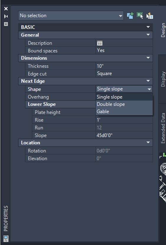
the roof tool you want to use and select the tool. You can also click the Home tab of the ribbon, build panel, Roof Slab drop-down and select Roof. On the Properties palette, select Single slope or Double slope for Shape (see Figure 5). In the drawing area, specify points for the corners of the roof. When you are finished specifying points, press Enter.
You can create a single sloped roof and set each edge to gable as needed. You can specify a slope for the gable ends to create a hip. You can even create a gable on an existing roof by gripping any ridge line point and stretching it past the roof edge. Open the tool palette that contains the roof tool you want to use and select the tool or use the Build panel on the Home tab of the ribbon. On the Properties palette, select Single slope for Shape. In the drawing area, specify the first point for the first roof edge. Specify the second point to complete the first sloped roof edge. On the Properties
AutoCAD
palette, select Gable for Shape. In the drawing area, specify the next point to create a gable roof edge. Select Single Slope for Shape. Specify the next point to create a sloped roof edge. Select Gable slope for Shape. Specify additional points as needed to define the roof and press Enter. To create a clipped gable roof, you first need to convert the gabled roof to roof slabs.
You can create a roof that is based on a selected closed set of walls and has the properties of the roof tool you select. You can edit these properties after creating the roof. The roof takes its plate height from the top of each wall segment. Open the tool palette that contains the roof tool you want to use. Right-click a roof tool and click Apply Tool Properties to Linework and Walls. Select the walls to convert and press Enter. If the walls you select are not closed, a roof is added to the top of each wall segment. When prompted to erase the original geometry, press Enter to keep the wall or enter y (Yes) to erase it. Edit the properties of the roof on the Properties palette, if needed.
You can create a roof that is based on a 2D polyline and has the properties of the roof tool you select. You can edit these properties after creating the roof. Draw a closed 2D polyline in the shape of the intended roof in the location where you want to place the roof. Open the tool palette that contains the roof tool you want to use. Right-click a roof tool and click Apply Tool Properties to Linework and Walls. Select the polyline to convert and press Enter. When prompted to erase the original geometry, press Enger to keep the linework or enter y (Yes) to erase it. Edit the properties of the roof on the Properties palette, if needed.

Melinda Heavrin is a CAD Coordinator & Facility Planner in Louisville, Kentucky. She has been using AutoCAD Architecture since release 2000. Melinda can be reached for comments and questions at melinda.heavrin@ nortonhealthcare.org.
Figure 5 – Single Slope Roof Properties
Training
Iwas an Autodesk Certified Instructor (ACI) from 2007 until early this year (2026). Nineteen years of teaching AutoCAD learners how to use AutoCAD effectively, primarily in a classroom environment at an Autodesk Authorised Training Centre (ATC). Now, don’t get me wrong, the classroom model is still valid. People still learn from people. However, with the way technology has advanced, a blended learning approach can now be much more beneficial to the individual.
Last month’s Inside Track article danced around various aspects of CAD management. Part of being a CAD manager is making sure your CAD team are informed and ready with the latest and greatest. To do that, they need to be trained and also trained how to put that training to good use. This is where that classroom model can seem a bit antiquated. There are many other ways where you can utilise the latest technologies to learn in a blended format to make the members of your CAD team much more effective and productive.
THE LINKEDIN POLL
A little while back, I posted a poll on LinkedIn. It asked about various methods of learning.
The poll asked about differing methods of learning. See Figure 1.
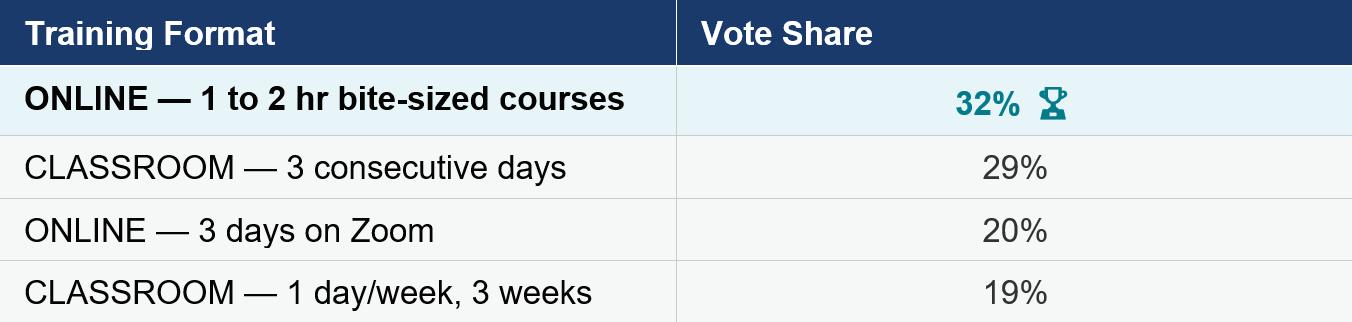
The top method of learning was surprising, as you can see. It was neck-and-neck between classroom learning and 1-2 hours of online learning, with online learning being the winner of the two. See Figure 2.
What can we take from that? Well, what it means is that you really do need to consider blended learning and develop your training strategy from there.
WHAT TRAINING WORKS AND WHY
It’s very easy to say that you SHOULD send your CAD team to a training centre to learn how to
use your incumbent CAD software application(s). However, it really is based on if you CAN send them. There are many facets of this decision path: project deadlines, operational capacity, budget, and the C-level take on training and its associated costs.
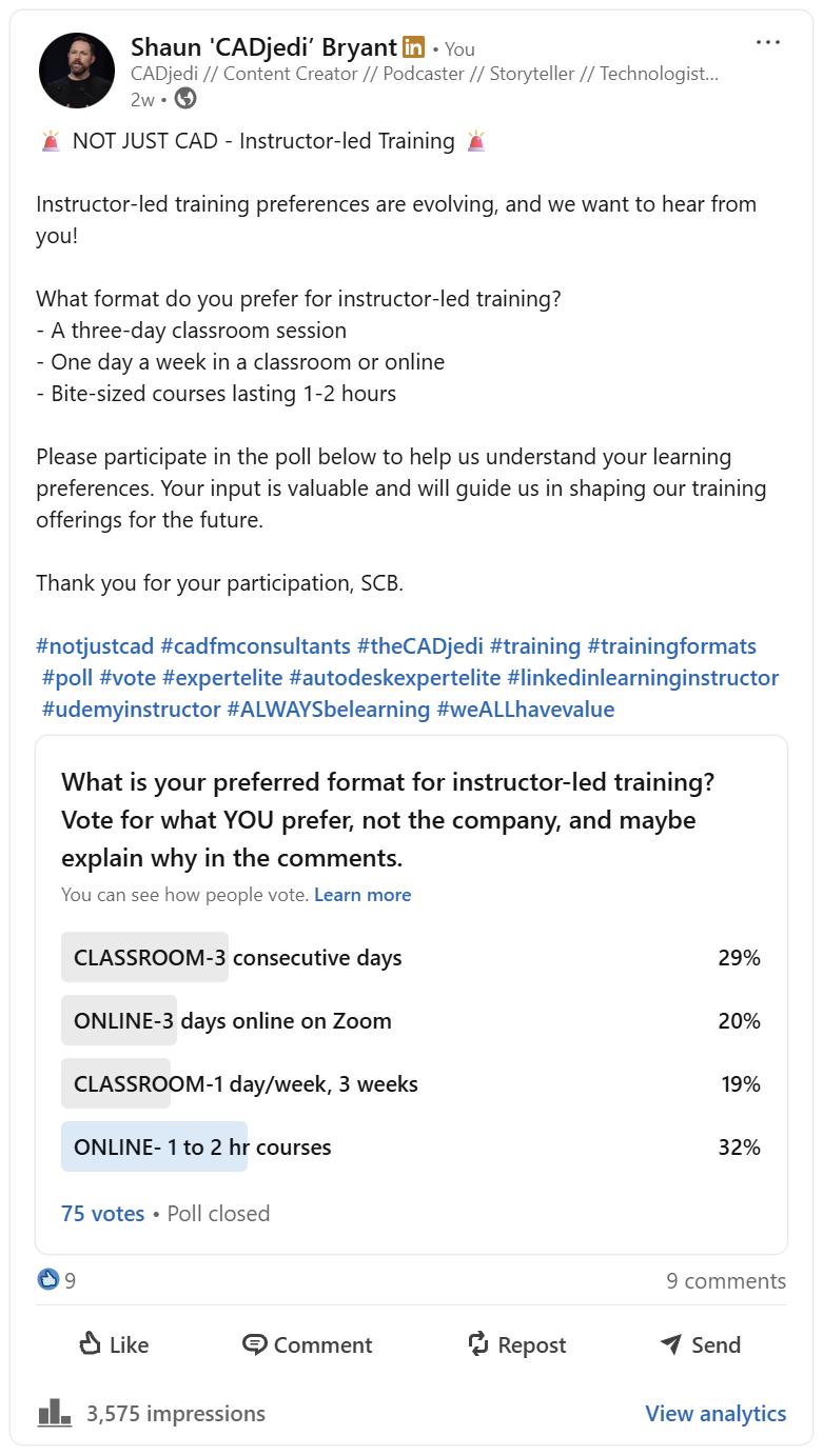
Figure 1
For example, have you ever tried to convince your managers/directors to allow a trip to Las Vegas to attend Autodesk University (AU)? For one, it’s Vegas. For two, it’s Vegas. And so, the argument continues…
Regardless of the training content, medium, and location, there is always this one argument I have heard so often about the associated costs of classroom-based training: -
“What happens if we train them, and they leave?”
My counter to this is very simple: -
“What happens if we DON’T train them, and they STAY?”
Your team MUST be trained. Which training methodology you use is up to you but based on my poll and (perhaps) your budget, a blended learning approach is often the best way forward.
INSTRUCTOR LED TRAINING (ILT)
ILT has been around for a long, long time. Think about it. Going to school was instructor led training. The teacher at the front of the classroom, telling you HOW to do something, with you then DOING that something, hopefully effectively, demonstrating proof of concept. An instructor led environment follows a similar method of learning but for adults learning commercial workflows and processes.
People will, most definitely, still learn from people, and peer-to-peer learning in a training centre is always of value, and being away from the ‘coal face’ does have its benefits for allowing the focus to be on the learning itself. There are caveats, though. The learners are away from their desks and not performing the operational tasks they are being
paid to do. This is where questions could be asked. Personally, as an ex-CAD manager, I can safely say that ALL instructor led training in a classroom WILL improve performance over time, if the knowledge gained is used immediately after returning from the classroom to the place of work. Always consider it as part of a blended learning program.
ONLINE LEARNING
MOOC – The acronym “MOOC” stands for Massive Open Online Course. There are numerous examples of this out there, such as LinkedIn Learning. As a LinkedIn Learning [in]structor, I have created over 90 courses for the LinkedIn Learning library, all with specific learning concepts and workflows, primarily for AutoCAD. Take a look at my courses there to get an idea of how a MOOC works: -
https://www.linkedin.com/learning/instructors/ shaun-bryant
VAWK – The acronym “VARK” represents four distinct sensory modalities: visual, aural (auditory), read/write, and kinesthetic. Each modality describes a different way individuals prefer to receive and process information. Visual learners excel with graphical representations, while aural learners thrive in auditory environments like discussions and lectures. Read/write learners prefer written information, and kinesthetic learners learn best through hands-on experiences. A perfect example of this in the marketplace is Global eTraining (GeT), whose AI-based learning system encompasses the VAWK methodology. Pop over to their website to see how their take on VAWK applies to their content: -
https://www.globaletraining.ca/
(Also, as an AUGI member, GeT offer 20% off their listed costs!)
Figure 2
Online learning offers a way of allowing your CAD team to learn online, at their own speed, and gives them much more flexibility to be present in the workplace, and learn in shorter, more focused and defined ‘bursts’, often digesting EXACTLY what they need in a more ‘just in time’ fashion. This can be highly beneficial for onboarding new staff, or making sure that team members are fully up to speed with skills needed for a particular project.
BLENDED TRAINING
How do you combine instructor led training with online learning?
Well, the answer to that question is incredibly simple. Use the classroom and the instructor led training as your fundamental foundation. Send ALL new CAD team members on their ‘essential training’ course – for example, AutoCAD Essential Training – to learn all the basic principles they need to learn to be effective as a member of the team. Call it boot camp, if you like.
Then, as they develop their skill set working ‘on the tools’ back at work, you can start to see their strengths, weaknesses, and their desire to learn more. That’s where the online learning is useful. It is lower cost than classroom-based, instructor led training and is much more focused. They can build up a playlist of the shorter, more activityfocused courses they want to watch and learn from, building up the necessary skills to be a much more rounded CAD user. This, in turn, makes them a much more valuable member of the team.
ALWAYS BE LEARNING
My business argument to your managers/directors is this. Do you want a highly effective CAD team, or one that just manages to get by on each project? Do you want your new starters to hit the ground running, or just get by with word of mouth in the CAD room/studio/office? As an ex-CAD manager, I know which I would prefer. Therefore, adopt my hashtag, #alwaysbelearning. Adopt a blended learning strategy, and remember: -
“What happens if we DON’T train them, and they STAY?”
IN CONCLUSION…
I sincerely hope that this month’s INSIDE Track has allowed you to think about how you ensure that your CAD team are informed, empowered, and productive. Maybe consider certification as an end goal for your CAD team, where they have a structured blended learning path to follow with the goal of achieving professional certification at the end of it.
Certification is a superb benchmark of knowledge, and it proves that your CAD team are up to speed for the task at hand. I might even use certification as a topic for Inside Track in the future.

Shaun ‘CADjedi’ Bryant is a seasoned CAD and BIM veteran with over 38 years of experience in the industry. As a CAD subject-matter expert and instructor with practical experience in AutoCAD, BricsCAD, DraftSight, and Revit, Shaun creates clear, structured learning content that helps engineers and designers understand complex CAD and BIM workflows and apply them effectively in real project environments. He is known for breaking down detailed engineering processes into content that has helped over half a million learners strengthen core CAD skills, improve workflow efficiency, and communicate technical information more effectively. Alongside his instructional work, Shaun advises organisations on improving CAD communication standards and building stronger capability frameworks within technical teams through his company, CADFMconsultants. He also a huge advocate for user communities such as AUGI, building resilient connections between application vendors and their users. Shaun is also the owner of the Not Just CAD brand that includes The Not Just CAD blog and podcast. He is a true techie geek and runs CADFMconsultants // Not Just CAD from ‘The Workshop’ in East Yorkshire in the UK.
If you have some news to share with us for future issues, please let us know. Likewise, if you are a user of a featured product or news item and would like to write a review, we want to know. shaun.bryant@cadfmconsult.co.uk