
26 minute read
3ds Max Machine Learning and AI

from AUGIWorld
by AUGI, Inc.
3ds Max – Industry Insights
➲ Acceleration of online activity helps to boost 3D in the digital universe. As 3ds Max professionals standing at the forefront of the 3D realm, we can take advantage of the momentum. For this article, we will present areas expanding in this era of acceleration and how we can take advantage of it.
MACHINE LEARNING AND AI
Machine learning is advancing in technology at an incredible speed, impacting nearly every industry. We encounter machine learning daily. Netflix, Google, and Amazon use machine learning to target users to offer suggestions for content, searching, and shopping. Machine learning helps solve complex problems from estimating cancer risk, to determining the price of homes.
I will present a simple (perhaps crude) explanation of the machine learning process. Imagine ten people in a room. Five have red shirts, and five have blue shirts based on various characteristics of the people. We present a problem for the computer: determine which shirt ten different people should be wearing. The computer will attempt to accomplish these tasks using complex algorithms. This process is called machine learning. A key strength of machine learning is the computer’s ability to accept and review near-infinite levels of data. For example, in the scenario with the ten people I provided, we could limit the computer to only having the gender of the people or input everything from what types of films the people like to anomalies in their DNA. The computer will attempt to categorize and classify data, making their decision based on that input. With the ability to accept infinite levels of information, no requirement for sleep, never aging, becoming exhausted, or dying, machine learning has extraordinary advantages.
So, let me explain how this impacts us who work with 3D. To generate professional 3D content, manipulating video and photography is one of our most common tasks. A few of these


tasks include up-resing, denoising, tiling, perspective correction, and object-aware/content fill. In each of these cases, developers are working to apply machine learning to use the data available to help categorize, classify, and analyze the pixels on images (or frames in a video’s case) to determine how to adjust them. So, let’s talk about Figure 4 – Creating Seamless Textures these cases. Denoise: Removing unwanted pixels from an image. In the past, Up-resing: Increasing the size of an image. Traditionally, when we change an image resolution from 100 pixels by 100 pixels to 800 pixels by 800 pixels, the process leaves us with a mosaic and Minecraft-worthy graphic. Machine learning methods allow us to increase the size of an image with better quality. Figure 1 shows the difference between an image scaled up traditionally versus one reducing render time meant unacceptable quality, resulting in sub-standard images covered with unwanted pixel dust (specks). Denoise technology allows us to remove those specks, producing an acceptable image with shorter render times. With 3ds Max 2021, you will find the Denoiser tab inside the Render Settings displayed in Figure 3. scaled up using up-res technology. Pay attention to the pixelation (mosaic pattern) on the roof with the traditional one compared to the higher quality image resized using up-res technology. Tiling: Duplicating a texture across an object. Before procedural tools, creating seamlessly tiled textures was a manual process. We would take a photo of a texture (a wall, for example) and shift it In most applications, we have the option to choose our method for the up-res. Take a look at Figure 2, a scaled-up portion of the image demonstrating the differences between up-resing in Photoshop using the Nearest Neighbor method versus up-resing using the so that the top left corner of the image was centered, then extract the center portion of the original image and combine it with that to get a tileable texture. Before and after, we would have to clean up anomalies. Figure 4 demonstrates the process. Bicubic Smoother. The Bicubic option seems to apply a software gradient to the upper edge. Essentially, it is an antialiasing effect. Perspective correction: Cameras in real and digital worlds present images with distortion. Perspective correction fixes this distortion. Additionally, perspective correction is applied to align objects with their environment. See Figure 5, where I imported a 3D model from 3ds Max into Adobe Dimension, then used the environment match tool to adjust the perspective and produce a product rendering; this makes it appear so that my product (in this case, a toy house) rests on the top of a table or desk.

Figure 2

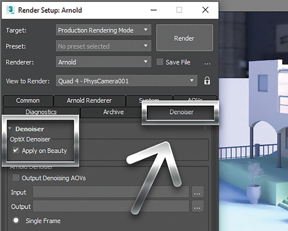
Figure 5 – Product Presentation with Adobe Dimension
Object-aware/content fill: Removing a portion of an image and filling it back in with content matching the surrounding area. This tool increases the speed we can remove unwanted content for our renders quickly. See Figure 6, where I selected the general area of the elements I wanted to remove on the left of the image, and the
result produced displayed on the right. This process takes only a few seconds to complete.
VIRTUAL INFLUENCERS
The next item making waves in the 3D industry is virtual influencers.

Figure 6 – Content-Aware Fill With the internet making available influencers in epic proportions, investors are becoming more interested in capturing the market. Business Insider Intelligence estimates brands increasing their annual budget for influencer marketing from eight billion to fifteen billion.

Today, like it or not, influencers aren’t just our favorite sports players representing their underwear, socks, or shoes anymore. They now come in 3D complete with environments, animations, shorts, music, dancing, have feelings, become brand ambassadors, fashion models, and even wear masks. Take a look at Figure 7. Riot Games created social media accounts where they act out the life of one of their champion characters online, Seraphine, who is a songwriter, producer, and pop star. Fans follow the life of Seraphine as she cooks, plays guitar, travels, and more.
Why would investors be interested in this, you ask? Well, they do not have to pay 3D characters. The characters don’t die, don’t get drunk, don’t get addicted to drugs (unless they want them to), don’t lick donuts at a donut shop (also, unless they want them to), can speak every language, and can reach any place in the world at the same time. Now, couple that with machine learning and imagine what you get. If you want to learn more, visit VirtualHumans.Org.
SUMMARY
As creators using 3ds Max, it is essential to pay attention to trends to avoid wasting time, money, and effort while capturing opportunities as they appear and producing the best content possible. It is crucial to use the tools available to us to create content efficiently. If you rendered a scene realizing it was a bit too small, try up-resing. If you want faster render times, try reducing the setting, then denoise it. If you wish to present your product well, import it to Adobe Dimension and match its perspective to the prebuilt environment. If you want to remove objects from a video to camera track and insert your proposed building, use object-aware and content-fill tools available in Adobe products. Finally, even if you always wanted to be an influencer but thought you couldn’t, maybe you can create one.
Brian Chapman is an Autodesk Authorized Developer, Digital Artist, Designer, and a CAD Application Specialist for an engineering firm located in Las Vegas, Nevada. Brian shares tips and tricks at procad.blog with a portfolio of digital artwork and renderings at emptypawn.com. Brian’s email is procadman@pro-cad.net
Office
APEXX S3, the world’s fastest Autodesk workstation professionally overclocked to 5.4GHz, is purpose-built for Revit, AutoCAD, 3ds Max, and more.
Download the free eBook on how to configure your workstation for ultimate Revit performance.
Download eBook
On-the-Go
GoBOXX SLM, the ultra-thin laptop purpose-built for 3ds Max, Maya, Revit, and more, empowers you to create from anywhere.
Watch Video


Enterprise Remote


FLEXX, purpose-built for enterprise organizations, enables your team to remotely access Autodesk data, content, and projects with the power and performance of a desktop.
Watch Video
Cloud
BOXX Cloud frees your AEC team from their desk side computers and enables them to work remotely with identical, seamless, cloud-based Revit performance.
Download the free BOXX Cloud eBook filled with vital information you won’t find anywhere else.
Download eBook
Storage
BOXX Storage provides secure, next generation NAS data storage (or SAN) for surveillance, backup, and archive within demanding, high performance Revit workloads. Download the free storage brief featuring product profiles for a variety of storage needs.
Download Brief
(888) 302-0223
512-852-0400
boxx.com/augi
Civil Corridors – We Don’t Always Need Them

➲In the Civil CAD world, most of us know how to work with roadway corridors. We have fumbled thru at least the basics of developing center/ baselines and attaching assemblies to help us get the 3D modeling that we need to generate our final road grading. From there, if we have the patience and appropriate training, we can work from corridor limits outward to start developing lot or pad site grading designs. Let’s face it though: none of this is quick, easy, or in any way user friendly. Most of us do everything we can to avoid the endless struggle that is corridor creation and the myriad steps it entails for us to get such basic design information.
Well, how about we work our entire 3D grading design without ever touching a corridor or an assembly? I know, you’re thinking I’m going to talk about some cool new software or plugin that you need to buy, right? Nope. I am talking about handling everything you need, from the centerline of road layout thru final grading, using nothing but tools you’re already comfortable with. Don’t believe me? Just follow along with me in this article and you will! For this article, I am going to be using Civil 3D for my design tool (It doesn’t really matter which version you’re working with.)
We begin with a simple Alignment. Alignment creation is one of the easiest, and fastest, processes in grading design. It is where corridors begin and it’s where we are going to start our “corridor free” design journey as well. Use the “Alignment Creation Tools” option, or “Create Alignment from Objects” to begin your design from a polyline you’ve already drawn on screen. Either way, we are
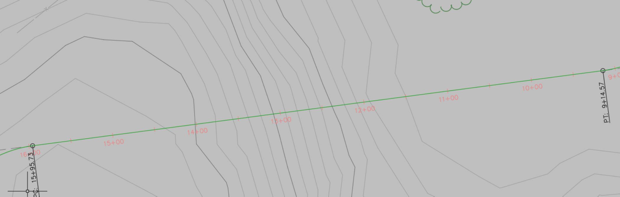
just looking to get a 2D layout of where the road goes, as shown in figure 1.
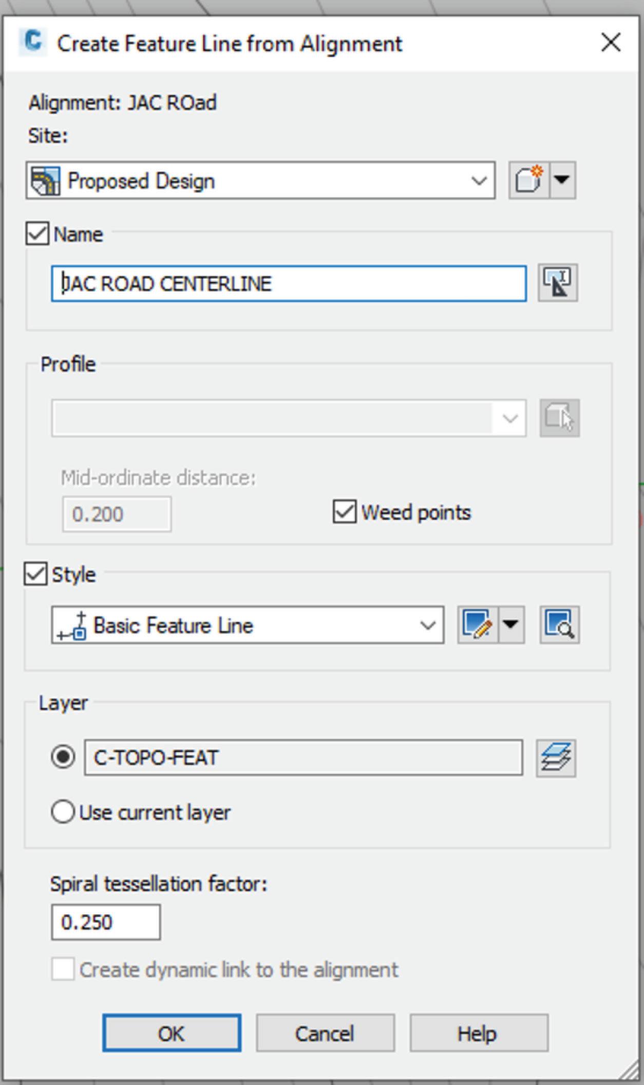
Figure 2: Feature Line Dialog Just what you would do to start a corridor, right? Then you would move into creating profiles, assemblies, regions, etc. Instead, all we are going to do here is use the “Create Feature Line from Alignment” tool. The system will allow you to create a Feature Line, to which we can quickly add slopes, and elevations at all needed stations, PC/PT, etc. Just select your alignment, then fill out the dialog (figure 2) and select OK.
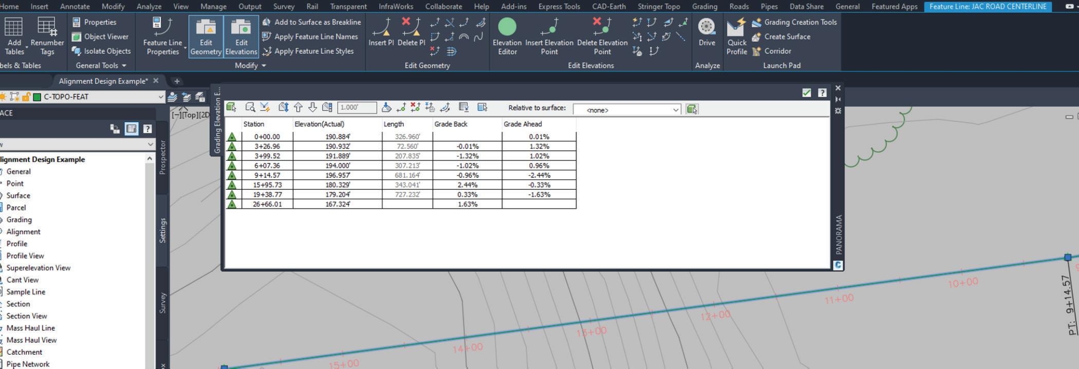
Once we’ve got a Feature Line, we can go into the Feature Line Elevation Editor off the ribbon bar (see figure 3) and we can adjust the specific elevations at each bend point on our design, or even change the grade in/grade out values to set fore/back slopes at the centerline of our road.
Once we’ve set all the elevations for the centerline, we can use the “Create Feature Line From Stepped Offset” tool, to easily offset from the centerline to our EOP/ETW at a -2% Grade to allow for the cross-slope of the roadway (see figure 4). These offsets calculate their elevations by adding/subtracting the % value you enter for grade and multiplying by the distance of the offset (i.e. 12’ for a typical lane, etc.). Essentially, it is a simple rise/run calculation.
I can use the same tool, to “offset” top of curb, back of curb, sidewalks, easement lines, etc. each with their own slope controls between line segments. The idea is to structure a “wireframe” of your site, using simple offset feature lines. Once you have established those, you can do two different things (see figure 5).
1. Grade Side Lots Using Feature Lines
This is pretty simple; you’re just going to use the basic Feature Line commands to generate the grades at the sides of individual lots. You can snap to specific points on your frontage (see below) or easement and begin creating side lot lines, using Feature Line slope/grade/elevation tools to control how the sides of each lot go up and down. This makes it easy to create swales and/or berms between properties, perpendicular to the offset lines we created.
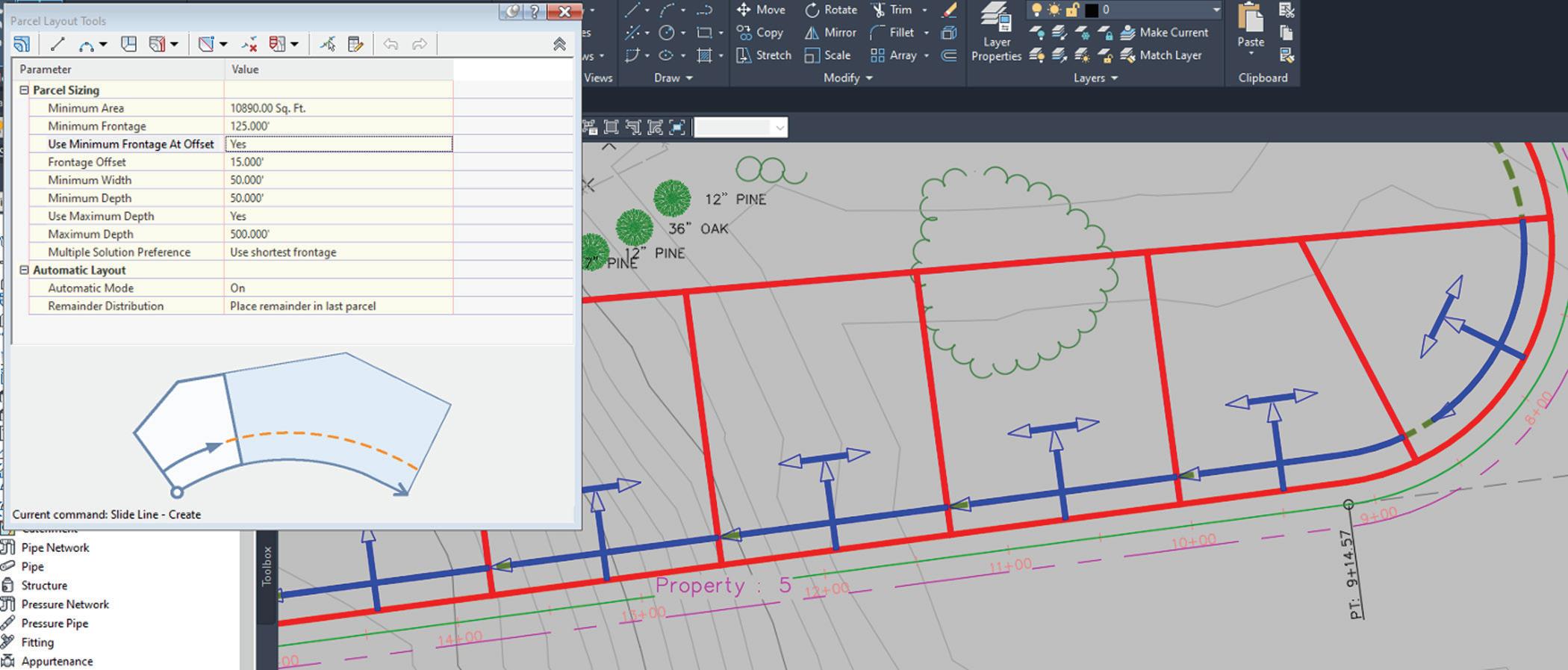
2. Grade Using Parcel Tools
A lot of folks do not realize that Parcel Segments can have elevation and fore/back slopes applied to them in exactly the
way that a Feature Line can. That means we can take advantage of the Parcel Layout tools and create dozens of lots at once, say for a subdivision, and have each already set at grades we can use for building a 3D surface. That is an immense time saver and can dramatically speed up the grading process. NOTE: The key thing here is that Feature Lines themselves cannot be used as Parcel definitions but use the eXplode command on them once and they’re 3d Polylines, with elevations, which work just fine!
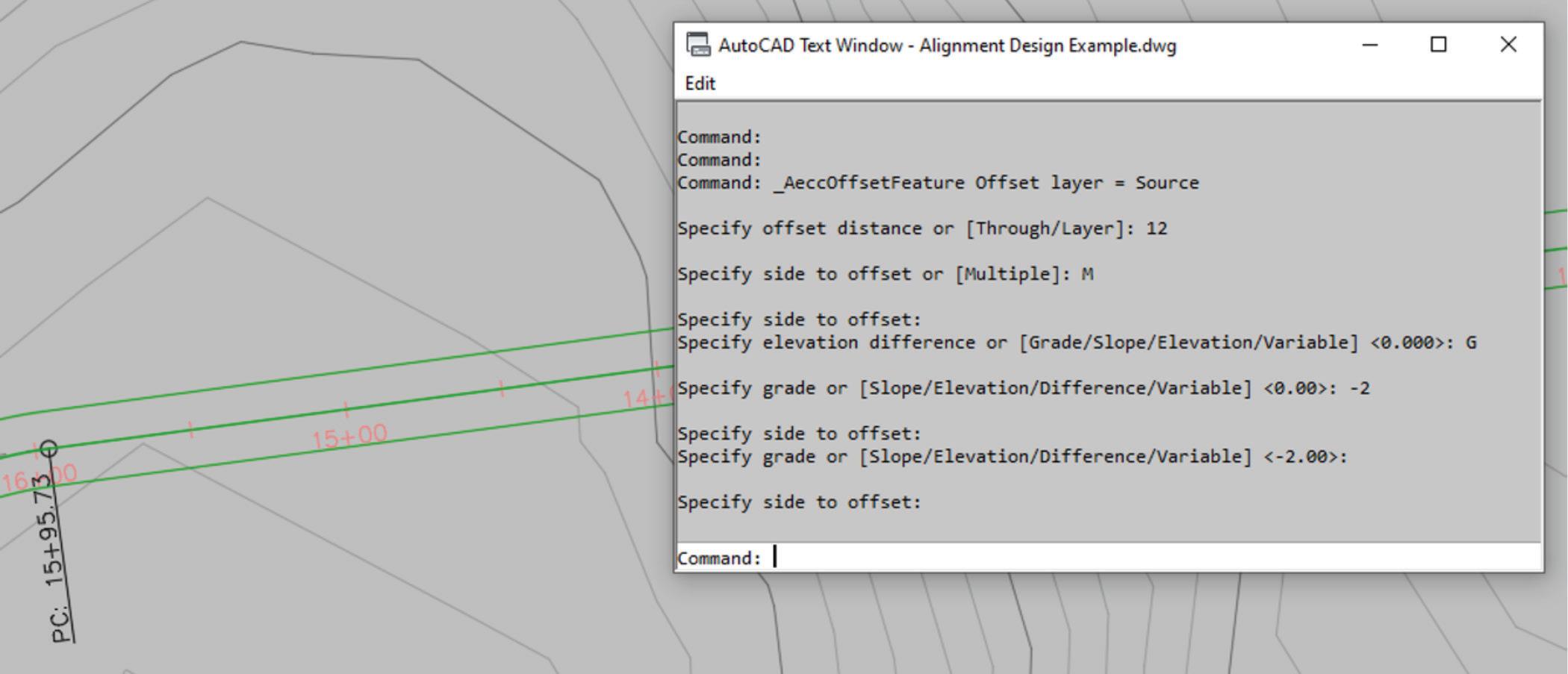
Figure 4: 12’ Offsets Created @ 2% Cross-Grade
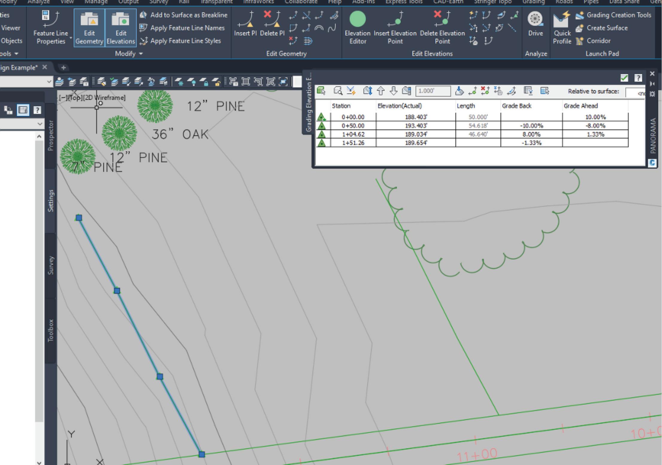
Figure 6: Parcel Creation Tools
Civil 3D 2021 PRODUCT FOCUS
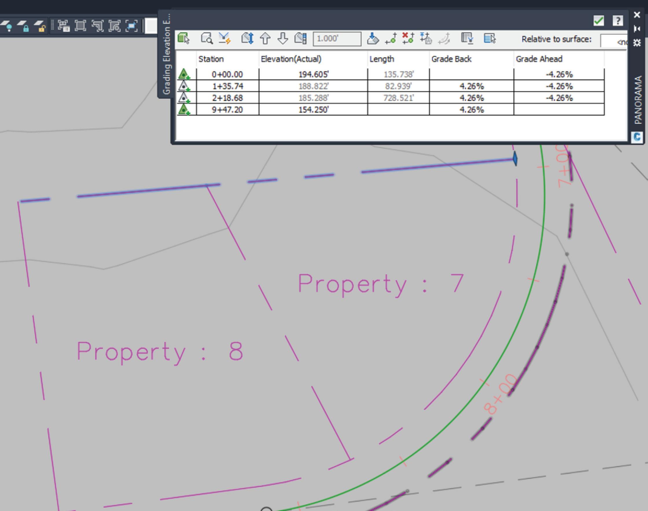
Once the parcels are laid out, you can click on them and run the “Elevation Editor” tool to view/modify the elevation and slopes for each parcel segment and PI (see figure 7). This methodology is much faster than manual placement of side lots, but there are some limits to the initial editing of the side lot parcel segments. You will have to eXplode them in order to add/remove PI’s (vertices). By default, the side lines are straight slopes that go from front yard to rear yard.
Ok, so these are all great tools, but what is the point here? After all, I said we were going to develop our grading surfaces with these tools, not just some parcels and curb lines! Well, that is the purpose of our wireframe structure: we’ve developed a series of linear objects, with elevations at each vertex, that we can now use as source objects from which to define a grading surface.
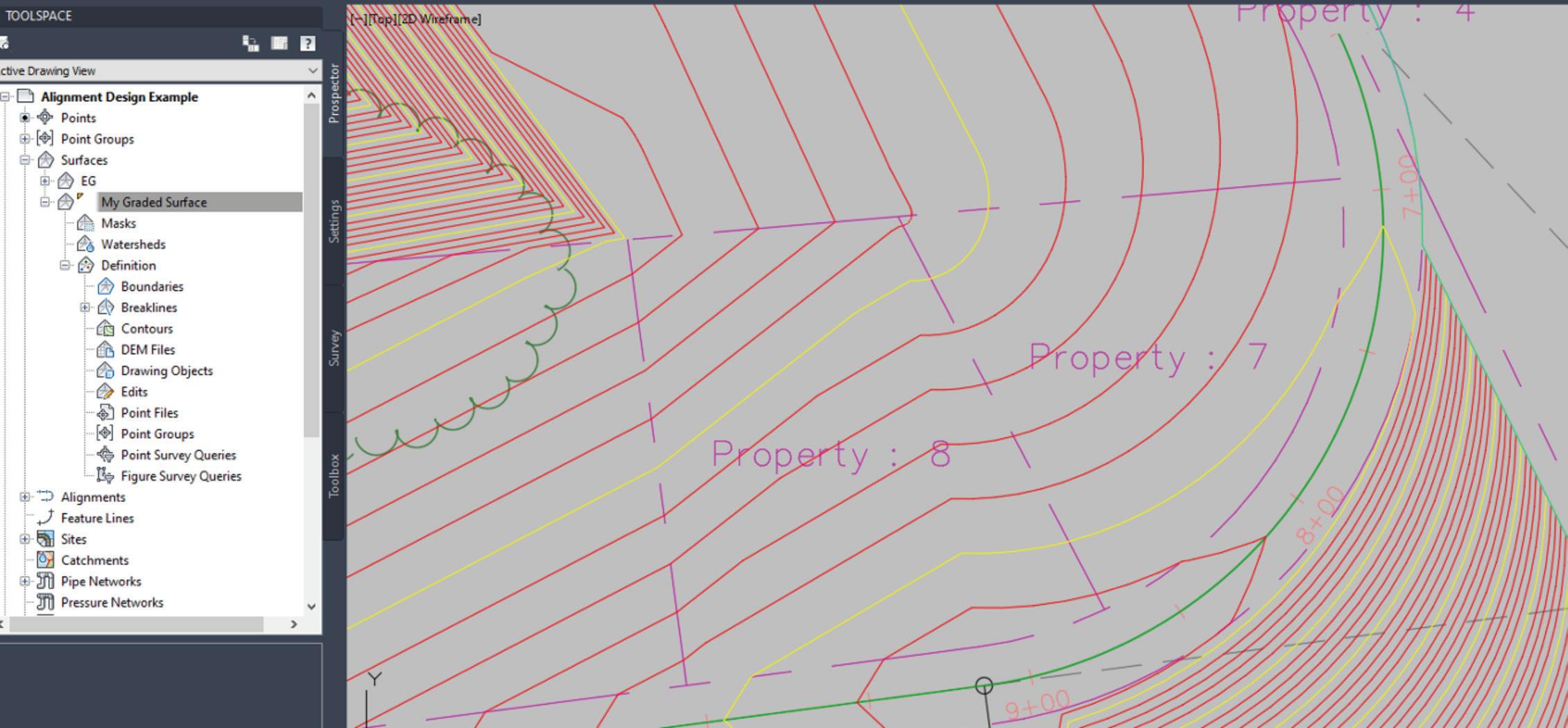
All we have to do is create a new surface, just the way you normally would, then use the feature lines and parcel segments we designed as “Breaklines” within that surface (yup, just pick them all as breaklines in one shot – it’s that easy!) You will see that your road, curbs, sidewalks, swales, side lot controls – everything we’ve done are incorporated into the surface and we get the final contouring done for us in seconds, shown in figure 8.
The big thing to note here is that –as I promised—we never touched an assembly, corridor, or profile, yet we have a fully developed and accurate road design. Not just that, but we’ve even completed the surrounding grading design and all of our controls (feature lines, etc.) that are still dynamically linked to the surface so that if we need to go back and update the design later on, we just change slopes/ elevations of the features and the surface adjusts. That is important because, let’s face it, every design we create is going to change a hundred times before we get to the final submittal. Editing simple feature lines and alignments is far easier for most of us than getting into the Corridor Section Editor or dealing with the confusions of assemblies and sub-assemblies with corridor region targets and vertical vs. horizontal code controls! Don’t worry if you’re not sure what all those things are, if you follow the process I’ve outlined in this article, you may never need to!
I will sum it all up by saying this: Corridors are fantastic tools, and they are wonderful for doing full blown roadway designs. If, however, all you really need for your project is the finished grading design and a few standard pavement details, then Corridors are a time-consuming overkill that you will want to avoid. Stick with simple tools that you know how to use and get your projects done in days, instead of weeks.
Jim Coppinger has over 30 years’ experience in the design/build industry, working in estimating, project management, and both architectural/civil design. With decades of practical experience for large design/build firms throughout the U.S., Mr. Coppinger brings a real-world voice to the construction technology arena. He is also a noted speaker and writer on best practices for implementing practical software solutions in the AEC community. Since founding ZenTek Consultants in 2016 with his partner Rocco Parisi, they have helped hundreds of firms implement, configure, and optimize their design/build workflows. Mr. Coppinger is also the host of The CADDle Call podcast - the leading, nationally acclaimed resource on design/build technology.
Checklists

➲It seems like people love checklists, or they hate them. Personally, I love them. (So does Santa) But they do not apply to everything. I would suggest you not have a checklist for proving you love your spouse. You may use a checklist when a big event is coming, but not to prove you love them. “See, I love you… I said it three times last week, as per the checklist and I made the bed once last week on my designated day. Of course I love you.” Checklists do however apply to a lot of things at work… and so I use them.
Back in Mid-2016, I wrote an article on Task Lists for AUGIWorld. Task Lists are a listing of the things I need to get done. That article provided ideas on why you need to manage your time and prioritize your work. I ended the article with ideas for making the Task List. Go back and read that when you have time.
Now I move on to the Checklist. But wait, aren’t they the same thing? They may look like it, but a Checklist differs from a Task List. Task Lists help you not forget to do something. Once completed, they can be removed from the list. Checklists organize what you need to do, review, or do over and over. It helps you not to forget something because the Task you are doing has become routine. It also assists you in training others. Checklists also help you verify that things are included, excluded, added, or removed.
NATIONAL CHECKLIST DAY
You may have missed it. It was on October 30th. According to nationaltoday.com, there are several reasons why we love checklists…
It keeps you organized. Do you have a truckload of things to do and you don’t know where to start? First things first with a checklist. This will help you organize your thoughts and your tasks. It makes things visual. Putting all your tasks down in your checklist will help you see what you need to get done in its entirety. In case you C. forget anything, you have a visual reminder. Consider colorcoding your list. It brings a sense of accomplishment. It feels amazing to check off each completed task. When you do the hard tasks first, for the rest of the day, all your remaining tasks seem easier.
I agree with all of these and want to add a few more.
D.
E.
F.
G.
H. It helps you repeat the same things again and again. When defining a process, this is critical. As you work through the checklist, you can add or remove things as you think of more or think of ways to expedite efforts. It helps training others or have people help you out. With a checklist, anyone can step in and take over, or learn to do it themselves.
It helps you review all the items needed and may uncover automation opportunities or areas where you can reduce the checklist by uncovering non-needed items. It helps you NOT assume things are done. With a checklist, you can verify that everything is in place and completed. It lets you “trust but verify” – one of my mottos. Sure, I think I do a good job, but check the list to see if I did it all. Sure, I think you are good at what you do, but I check the list to make sure nothing slips through the cracks.
Checklists can be for procedures and processes. They can be in a specific order and numbered so that one thing is done before another. They can be simple check boxes and list out what is to be included or excluded. Like a list of what to take when you go camping. They can be grouped or free flowing. What makes the checklist is that they do not tell you how to do things, just what needs to be completed.
Occupational Safety and Health Administration (OSHA), under the US Department of Labor, has a checklist for your computer workstation ergonomics. It helps you verify that you have thought
of everything needed for comfort, health, and productivity. You can see it here - https://www.osha.gov/SLTC/etools/ computerworkstations/checklist_evaluation.html
It takes into account your posture, chair, monitor, keyboard, mobile devices, accessories and more. Go check it out and see how you fair in your home office or work location.
Here is a highlight…
MONITOR – Consider these points when evaluating the monitor and its placement.
The monitor has sufficient adjustability so the top of the screen is at or below eye level so the user can read it without bending their head or neck down/back. Adjustability is sufficient so users with bifocals/trifocals can read the screen without bending the head or neck backward.
There is sufficient room so the monitor can be placed at a distance which allows the user to read the screen without leaning head, neck, or trunk forward/backward. (Generally, about 18 to 20 inches or arm length) Monitor position is directly in front of the user, so they do not have to twist head or neck.
If multiple monitors are used, the position of the primary monitor is directly in front of the user and the other monitors are directly beside it. If time is split evenly between monitors, they are next to each other within a comfortable viewing angle with minimal head movement. Glare (from windows, lights) is not reflected on screen causing the user to squint or assume awkward postures to clearly see information on the screen. Monitor brightness and contrast is adjusted for comfort.
I did pretty good on this section, but others need some work.
Way back in the dark ages, I made a CAD Review Checklist for reviewing files prior to sending them to clients or consultants. You can see it at http://www.caddmanager.com/CMB/2007/01/cadfile-review-checklist/
Here is a portion: +++++++
Checklist for reviewing CAD Files:
1. Directory Structure a) Are the folders correctly named? b) Are there any unneeded folders? 2. Files and File names a) Are the filenames correct? b) Are there any junk files that should be removed? 3. Layers a) Is the layer list clean?
b) Are the layer names correct? c) Are the objects on the right layer? d) Are the linetypes correct? 4. XREF Attachments a) Are the attachments on the right layer? b) Are they in the correct location? … much more +++++++
IDEAS FOR CHECKLISTS
Here are some ideas and I am sure that you can come up with many more: 3 New project setup 3 Computer setup/refresh/swap – what needs to be done when giving a user a new computer 3 Diagnosing a file problem 3 Creating content for CAD libraries 3 Revit Family development 3 Project archiving 3 Training checklist 3 When vetting software for purchase 3 Quality Assurance – when accepting files/models from others 3 Checking files against CAD Standards
Once created, always look for things to add to the list or remove. Checklists are never static. As you learn new lessons, add items to the checklist.
WHEN NOT TO USE A CHECKLIST
Like I mentioned, expressing love to a spouse, or child may not be the best use of a checklist. Others might be when you are in a pinch and need to act fast. No time to go get out the checklist. Stop the bleeding and then go look for the list. And when you are researching options, no checklist may be viable once you really do not know where you might end up. Checklists usually are developed once you have an idea of what is needed.
So, you have a good starting point. Now go out and make some checklists or review the ones you have… but first check off “reading AUGIWorld” from your list.
Mark Kiker has more than 25 years of hands-on experience with technology. He is fully versed in every area of management from deployment planning, installation, and configuration to training and strategic planning. As an internationally known speaker and writer, he is a returning speaker at Autodesk University since 1996. Mark is currently serving as Director of IT for SIATech, a non-profit public charter high school focused on dropout recovery. He maintains two blog sites, www.caddmanager.com and www.bimmanager.com.
Welcome to AUGIWorld Inside Track! Check out the latest opportunities to advance your skills, processes, and workflows in your firm with the most current AEC-related software and hardware updates available.
ParametricText
https://apps.autodesk.com/FUSION/en/Detail/In dex?id=2114937992453312456&appLang=en&os= Win64
Autodesk Fusion 360
ParametricText is an Autodesk® Fusion 360™ add-in for creating Text Parameters in sketches.
Text parameters can be pure text or use parameter values by using a special syntax. There is also a special parameter, that contains information about the document’s version and saves date.
All parameters are stored within the document upon save. The texts are always “rendered” in the sketches, so they can be viewed without having the add-in. However, to correctly update the values, the add-in is needed.
AUGIWorld brings you recent developments in Autodesk and related software items
If you have some news to share with us for future issues, please let us know. Likewise, if you are a user of a featured product or news item and would like to write a review, we want to know. brian.andresen@augi.com
MEP_UpDown
https://apps.autodesk.com/RVT/en/Detail/Index? id=5443718852969449845&appLang=en&os=W in64
Autodesk Revit Version: 2021 , 2020 , 2019 , 2018
It helps edit level offset up or down for coordination of MEP elements. With just split and input value, this add-in redraws elements automatically. MEP elements are duct, pipe, cable tray, and conduit. It can reduce modeling time and improve model quality.
MuM Multitool
https://apps.autodesk.com/INVNTOR/en/Detail/ Index?id=3826146264845665861&appLang=en&o s=Win64
Autodesk Inventor: 2021 , 2020 , 2019 , 2018

Autodesk Inventor Professional: 2021, 2020, 2019, 2018
MuM Multitool for Autodesk® Inventor® supports you in the timeconsuming activities in your every day. With the features listed below, you increase your efficiency in your day-to-day work and save time for the important things. MuM Multitool is a plug-in for Inventor and is thus readily compatible with other add-on applications. You can easily access the extended functions via the MuM toolbar. Options include:
Predefined printer templates: Predefined printer settings save time on every printout. For example, sheet size, color, scale, format, plot date, watermark, etc. can be predefined and recalled at any time.
Printing all IDW drawings from an assembly (IAM): Print all the drawings belonging to an assembly (IAM) without having to open each file individually. You can easily choose which files you want to print like and, thanks to predefined print templates, these are output in the correct format as desired.
Consolidate and display technical iProperties: A quick overview gives you an overview of the most important technical and physical properties of iProperties. For example, material, weight, volume, total length, parameters set to export, or detailed sheet metal parts are displayed.
Dimension favorites: Recurring dimension specifications such as tolerances, fits, dimensions, diameters, or special characters are configured once and can then be retrieved again and again and easily managed. In the inking mode, text can be highlighted in color; e.g. as a special note for the production.
Collective data for surface characters: Collective specifications for surface details are automatically compiled and updated at the click of a button thanks to MuM Multitool for Inventor. Fits list: MuM Multitools for Inventor creates tolerance tables on Inventor drawings and automatically fills them with the corresponding fits. Updates automatically apply in the list.

