
Virtual Tools for Retaining Wall Installation and Design


Preliminary Wall Sections
Simply enter data specific to your project to gain insight into possible solutions for your wall scenario.
Construction Details
Downloadable Redi-Rock retaining wall construction details to add to your plan set.
Knowledge Hub
Collection of guides, videos, case studies. Search with ease to find information related to your project or site scenarios.
Design Resource Manual
The ultimate guide for designing Redi-Rock walls, including an overview of every block in the Redi-Rock system.
Redi-Rock Wall+ Software (RRWall+)
A software program built for designing and analyzing Redi-Rock gravity and MSE walls.
Specifications and Redi-Rock Product Data Sheets
Design details and specifications for all Redi-Rock products.
Redi-Rock Block & Application Test Reports
Robust and reliable testing details so you can design and build with confidence.
SketchUp Files
Access more than 90 Redi-Rock SketchUp files to bring your gravity, MSE, freestanding, and hybrid retaining wall designs to life.
The Redi-Rock logo is a registered trademark of Redi-Rock International, LLC of Charlevoix, MI USA.
The Redi-Rock name is a copyright of Redi-Rock International, LLC of Charlevoix, MI USA.
The information contained in the Installation Guide has been compiled by Redi-Rock International, LLC to document the performance of the Redi-Rock products contained therein. It is accurate to the best of our knowledge as of the date of its issue. Information included in the Installation Guide has been prepared in accordance with generally recognized engineering principles and practices. This information should not be used without first securing competent advice with respect to its suitability for any general or specific application. Final determination of the suitability of any design information and the appropriateness of this data for a given design purpose is the sole responsibility of the user.
No warranty of performance by Redi-Rock International, LLC authors is expressed or implied by the publishing of the following Installation Guide.
Issue Date: December 29, 2025
Form No. RRI-001-122925IG
This manual is intended to serve as a guide for the proper installation and construction of a Redi-Rock® retaining wall. The recommendations and guidelines presented here are intended to supplement detailed construction documents, plans, and specifications for the project.
INTRODUCTION RESPONSIBILITIES
Redi-Rock supports a Total Quality Management approach to Quality Assurance and Quality Control (QA/QC) in the planning, design, manufacture, installation, and final acceptance of a Redi-Rock wall. This approach requires the responsible party at each stage of the project ensure that proper procedures are followed for their portion of the work. The responsible parties during the construction phase of a Redi-Rock wall include the Contractor, Engineer or Owner’s Representative, and Redi-Rock Licensed Manufacturer. Their specific responsibilities for compliance are as follows:
CONTRACTOR
The Contractor is responsible for providing construction according to the contract documents, plans, and specifications for the project. The Contractor shall ensure that employees engaged in construction of the Redi-Rock wall understand and follow the project plans and specifications, are familiar with construction methods required, and have adequate safety training.
ENGINEER OR OWNER’S REPRESENTATIVE
The Engineer or Owner’s Representative is responsible for construction review to assure that the project is being constructed according to the contract documents (plans and specifications). The representative shall fully understand the project plans and specifications and shall perform adequate field verification checks to ensure construction is in conformance with the project requirements. The presence of the Engineer or Owner’s representative does not relieve the Contractor of their responsibilities for compliance with the project plans and specifications. Construction Inspectors may also fall under this category.
REDI-ROCK LICENSED MANUFACTURER
Redi-Rock blocks are produced by independently-owned Licensed Manufacturers. The Manufacturer is responsible for the production and delivery of Redi-Rock units to the job site in accordance with published material quality, size tolerances, construction documents, plans, and specifications. The Licensed Manufacturer is responsible for adherence to any project specific QA/QC requirements for the production of precast concrete retaining wall units. Often, additional services—such as installation training classes—are available through the Redi-Rock Manufacturer.
PRE-CONSTRUCTION CHECKLIST
Before starting the construction of a Redi-Rock wall, take the time to complete necessary planning and preparation. This process will help ensure a safe, efficient, and quality installation. It will also help avoid costly mistakes.
SAFETY
Safety is of primary concern to Redi-Rock International. Redi-Rock walls must be installed in a safe manner. All local, state, and federal safety regulations must be followed. In addition, Redi-Rock International greatly encourages installers to set up company programs to help their people stay safe at work. These programs should address items such as: personal protective equipment, maintaining safe slopes and excavations, fall protection, rigging and lifting, and other safety precautions. Safety-training materials specific to a company can be found at www.osha. gov, by calling 1-800-321-OSHA (6742), or from the local government safety office.
ENGINEERING AND PERMITS
Obtain the necessary engineering and permits for the project. The local building department is an excellent resource to help determine the requirements for a specific project.
This installation guide is intended to supplement a detailed, site-specific wall design prepared for a project by a Professional Engineer. Construction documents for a project supersede any recommendations presented here.
REVIEW THE PROJECT PLANS
Take the time to review and understand the project plans and specifications. Make sure that the plans take into account current site, soil, and water conditions. Pay close attention to silty or clayey soils and ground water or surface water on the site as these can significantly increase the forces on the wall. A pre-construction meeting with the wall design engineer, construction inspector, wall contractor, and owner or representative is recommended.
UTILITY LOCATION
Make sure to have underground utilities located and marked on the ground before starting any construction. Call 8-1-1, go online to www.call811.com, or contact your local utility company to schedule utility marking for your project site.
CONSTRUCTION PLANNING
Develop a plan to coordinate construction activities on the site. Make sure the plan specifically addresses how to control surface water during construction.
MATERIAL STAGING
Store Redi-Rock blocks in a location close to the proposed wall. Blocks should be kept clean and mud free. Blocks should also be stored in a location which will minimize the amount of handling on the project site. Store geogrid in a clean, dry location close to the proposed wall. Keep the geogrid covered and avoid exposure to direct sunlight. Be careful where excavation and backfill material is stockpiled. Do not stockpile material over buried utility pipes, cables, or near basement walls which could be damaged by the extra weight.
MATERIAL VERIFICATION
Material planned for use as drainage aggregate between and behind Redi-Rock blocks and structural backfill material proposed for use in the retained soil zone of a gravity wall or in the reinforced and/or retained soil zones of mechanically stabilized earth walls must be inspected and verified to comply with requirements of the construction documents, plans, and specifications.
EQUIPMENT
Make sure the site has the proper equipment to handle Redi-Rock blocks and install the wall. Redi-Rock blocks are large and heavy. Make sure excavators and other construction equipment are properly sized to handle the blocks safely. (Figure 1)
Hand-operated equipment should include, at a minimum: shovels, 2 ft (610 mm) level, 4 ft (1.22 m) level, broom, hammer, tape measure, string, spray paint, laser level, pry bar, walk-behind vibratory plate compactor (capable of delivering a minimum of 2000 lb (8.9 kN) centrifugal force), and a 16 in (406 mm) concrete cut-off saw. (Figure 2)
Personal protective equipment should include, at a minimum: appropriate clothing, steel toe boots with metatarsal protection, eye protection, hard hat, gloves, hearing protection, fall protection rigging, and other items as necessary to ensure a safe working environment.
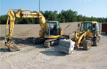
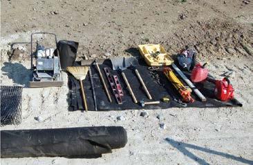
Figure 1 - Heavy equipment
Figure 2 – Hand-operated equipment
SUBGRADE SOILS
Proper base preparation is a critical element in the construction of a retaining wall. Not only is it important to provide a stable foundation for the wall, but a properly prepared base will greatly increase the speed and efficiency of the wall installation. Proper base preparation starts with the subgrade soils.
Existing soils must be removed to the bottom of the leveling pad elevation for the retaining wall.
The base and back of excavation should expose fresh, undisturbed soil or rock. Remove all organic, unsuitable, and disturbed soils that “fall-in” along the base of the wall or the back of the excavation. Always provide safe excavations in accordance with OSHA requirements.
The subgrade soil (below the leveling pad) should be evaluated by the Engineer or Owner’s Representative to verify that it meets the design requirements and to determine its adequacy to support the retaining wall. Any unsuitable material shall be excavated and replaced as directed by the on-site representative and per the requirements of the contract drawings, plans, and specifications.
Subgrade soils must be compacted to a density as specified in the contract documents, plans, and specifications but not less than 90% maximum density at ± 2% optimum moisture content as determined by a modified proctor test (ASTM D1557). (Figures 3 and 4)
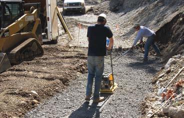
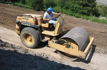
Figure 3 – Walk-Behind Plate Compactor on Subgrade Soils
Figure 4 – Mechanical Compaction/Road Roller (Not Shown in Subgrade Application Here)
LEVELING PAD
Base preparation continues with proper leveling pad construction. Redi-Rock retaining walls can be designed with an open-graded crushed stone, dense-graded crushed stone or graded aggregate base (GAB), or concrete leveling pad which supports the bottom row of blocks. The choice of which type of leveling pad to use is made by the wall design engineer and depends on several factors including the bearing capacity of the native soil, location of the drain outlet, and conditions at the base of the wall.
Open-graded crushed stone is typically used in cases where the wall drain can outlet to daylight (by gravity) somewhere below the elevation of the bottom of the leveling pad. (Figure 5A) The material should be 1 in (25 mm) diameter and smaller stone. A crushed stone meeting the gradation requirements of ASTM No. 57 (20 mm) with no material passing the No. 200 (74 μm) sieve is preferred. The leveling pad thickness shall be as designed by the wall design engineer. A minimum thickness of 6 in (150 mm) or 12 in (305 mm) is common. The leveling pad should extend at least 6 in (150 mm) in front and 12 in (305 mm) behind the bottom block. Make sure to check the construction documents for details.
Dense-graded crushed stone or graded aggregate base material is typically used in cases where the wall drain can only outlet to daylight somewhere above the bottom of the leveling pad. (Figure 5B) The material should be dense-graded crushed stone with between 8 and 20% “fines” which will pass through a No. 200 (74 μm) sieve. The leveling pad thickness shall be as designed by the wall design engineer. Minimum dimensions are the same as those for an open-graded crushed stone leveling pad.
The leveling pad material should be placed and compacted to provide a uniform, level pad on which to construct the retaining wall. Proper elevation can be established with a laser level or transit. Two 20 ft (6.10 m) long grade (screed) pipes can also be set to the desired grade and screed the crushed stone material between the pipes.
Figure 5B - Dense-Graded Crushed Stone Leveling Pad
Figure 5A – Open-Graded Crushed Stone Leveling Pad
Place the stone leveling pad in uniform loose lifts a maximum of 6 in (150 mm) thick. Compact the stone with a minimum of three passes with a 24 in (610 mm) wide walk-behind vibrating plate compactor capable of delivering at least 2000 lb-force (8.9 kN). This should achieve 85% relative density of the stone determined in accordance with ASTM D-4253 and D-4254. In-place density of the stone fill should be confirmed using ASTM D-6938. If a minimum of 85% relative density in not achieved, place the stone in smaller lifts or apply more compaction effort until the desired density of the stone is achieved.
Unless specifically included in the design calculations, do NOT place a thin layer of sand between the leveling pad and bottom block. This layer will reduce the sliding resistance between the leveling pad and bottom block.
In some cases, the wall design requires the construction of a concrete leveling pad. (Figures 5C and 5D) Construct the leveling pad according to the detailed plans for the project.
Some designs require a shear key in the bottom of the footing and/or a lip in front of the Redi-Rock blocks. These items would be shown in the project plans. If steel rebar is to be placed in the footing, secure the bars together with wire ties in the pattern shown in the construction documents. Use rebar supports to hold the rebar structure in the proper position in the footing.
Place wood formwork at the front and back of the concrete leveling pad or footing. The top of the formwork should be placed at the elevation of the top of the concrete footing so that the top can be screeded smooth in preparation for block placement. It is important that the top surface be smooth and level for full contact of the retaining wall blocks. Place concrete as specified in the wall design. Once the concrete has been allowed to cure to the minimum specified strength, place the bottom blocks and continue construction of the retaining wall.
Figure 5C - Concrete Leveling Pad
Figure 5D - Reinforced Concrete Leveling Pad
STAKING THE WALL
In order to ensure proper layout of the wall construction, staking the location is an essential step. For walls with corners refer to page 28. For curves, refer to page 27 of this manual for additional considerations.
Stake the proposed retaining wall layout at the face of the wall, including horizontal location, finished elevation at the top of and bottom of the wall, wall stationing, and any offsets from project baseline stationing. (Figure 6)
A string line or offset stakes are typically used to establish horizontal and vertical alignment. When offset stakes are used, the stakes should be placed at least 5 ft (1.52 m) but no more than 10 ft (3.05 m) in front of the face of the retaining wall. A stake should be provided at every elevation change and at a maximum of 50 ft (15.2 m) apart. Wall construction should start at a fixed point such as a building wall, 90° corner, or at the lowest elevation of the wall.
Mark any pipe penetrations through the retaining wall including type and material, diameter, and invert elevation of pipe. Locate any other existing or proposed utilities (including water, sanitary sewer, storm sewer, electric, fiber optic, cable, gas, irrigation, etc.) near the vicinity of the retaining wall.
Label distance to buildings or any other structures, property lines, construction limits, and offsets of these instances if located near the retaining wall.
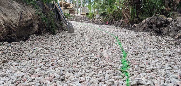
Figure 6 – Spray Paint can be Used for Staking
PLACING THE BOTTOM ROW OF WALL BLOCKS
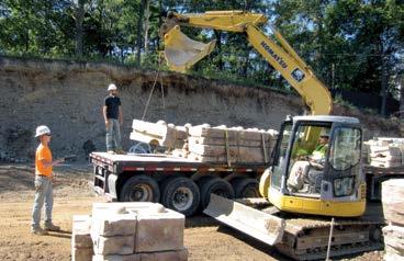
Redi-Rock blocks are typically delivered to the construction site using a flatbed trailer or boom truck. (Figure 7) Rubber tired backhoes, loaders, skid steers, or excavators are used to set the retaining wall blocks. (Figure 8) Make sure to use the proper sized equipment to handle the large blocks. All lifting chains, rigging, or slings must be OSHA compliant and safety rated for proper working loads.
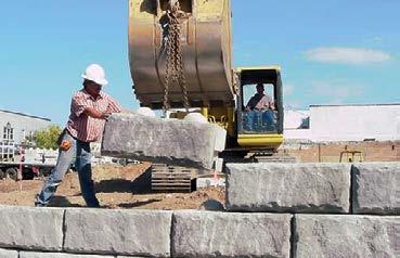
Place the blocks on the prepared leveling pad. Blocks shall be placed in full contact with the leveling pad and other immediately adjacent block units. (Figure 9) Block alignment should be established by lining up the “form line” where the face texture meets the steel form finished area at the top of the block, approximately 5 in (127 mm) back from the front face. (Figure 10)
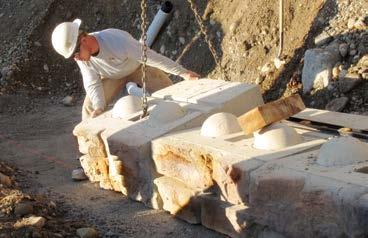
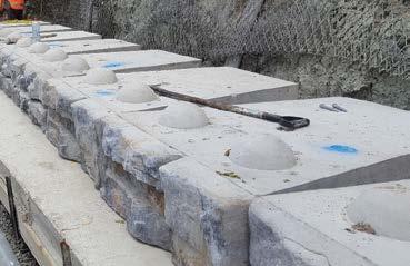
Figure 7 – Block Delivery on Site
Figure 9 – Placement of Bottom Row of Blocks on the Leveling Pad
Figure 8 – Excavator Placing a Block
Figure 10 - Form Line Alignment
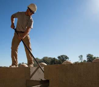
Check all blocks are level and aligned as they are placed. Small adjustments to the block location can be made with a large pry bar. Proper installation of the bottom block course is critical to maintaining the proper installation of all subsequent block courses within acceptable construction tolerance. It also makes installation of the upper rows of blocks much easier and more efficient.
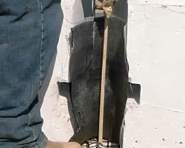
Place and compact backfill in front of the bottom block course prior to placement of subsequent block courses or backfill. This will keep the blocks in place as drainage aggregate and backfill are placed and compacted. If specified in the retaining wall plans, place an 18 in x 12 in (457 mm x 305 mm) piece of non-woven geotextile fabric in the vertical joint between the blocks to prevent the drainage aggregate and backfill material from migrating through the vertical joints between blocks. (Figure 11)
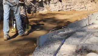
Place washed drainstone or open-graded crushed stone backfill between blocks and at least 12 in (305 mm) behind the wall. Stone meeting the gradation requirements of ASTM No. 57 (or regional equivalent) with no material passing the No. 200 (74 μm) sieve is preferred. Place the stone in uniform loose lifts a maximum of 6 in (150 mm) thick. Consolidate the stone with a minimum of three passes with a 24 in (610 mm) wide, walk-behind, vibrating plate compactor capable of delivering at least 2000 lb (8.9 kN) of centrifugal force. (Figure 12) This should achieve 85% relative density of the stone determined in accordance with ASTM D-4253 and D-4254. In place density of the stone fill should be confirmed using ASTM D-6938. If a minimum of 85% relative density is not achieved, place the stone in smaller lifts or apply more compaction effort until the desired density of the stone is achieved.
Figure 11 – Placing Non-Woven Geotextile Fabric
Figure 12 - Walk-Behind, Vibrating Plate Compactor
Place non-woven geotextile fabric between the drainstone and the remaining backfill material if specified. (Figure 13)
Backfill behind the drainage aggregate with material as specified in the project construction documents. Place the lifts as specified, but not to exceed 9 in (229 mm) maximum. Granular backfill shall be compacted to a minimum of 90% maximum density at ± 2% optimum moisture content as determined by a modified proctor test (ASTM D1557). Use proper equipment to ensure complete compaction of the backfill material. It may be necessary to wet or dry the backfill material, place the material in smaller lifts, and/or apply more compaction effort to reach 90% maximum density. Do not use any organic, topsoil, frozen, soft, wet, or loose soils when backfilling the wall.
Re-check all units for level and alignment and sweep the top of each course of blocks clean before starting construction of the next course.
INSTALLING THE WALL DRAIN
A drain is placed behind the Redi-Rock wall blocks at the lowest elevation where the pipe can safely outlet to daylight. Drainage aggregate should be placed to the bottom of the drain as shown in the construction documents. A 4 in (102 mm) perforated drain is commonly used for the drain pipe. Often the drain is encapsulated with drainage aggregate which is then wrapped with a non-woven geotextile fabric. The drain should run the entire length of the wall and needs to have proper outlets on the ends and at regularly spaced points along the wall. (Figure 14) Solid pipe should be used for weep hole outlets through the face or under the retaining wall. Care needs to be taken during installation to avoid crushing or damaging the drain pipe or outlets.
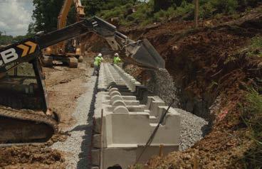
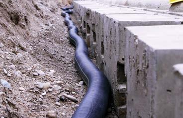
Figure 13 – Backfill Material
Figure 14 - Placing the Wall Drain
PLACING THE UPPER ROWS OF WALL BLOCKS
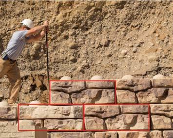
Once the backfill is fully placed and compacted for the block course below, place the next row of blocks in a running bond configuration where the vertical joint of the lower block units is centered under the midpoint of the block units above. If needed, a half block can be used at the end of every other row to maintain a running bond. (Figure 15)
Push the Redi-Rock blocks forward until the groove on the bottom of the block comes in full contact with the knobs on the blocks below. This sets the wall batter. Standard Redi-Rock blocks create a 5° from vertical wall batter scenario. Specialty Redi-Rock blocks can be produced to create 0°, 1°, 27.5°, or 43° wall batter options. Adjacent blocks shall be placed with their front edges tightly abutted together.
Place non-woven geotextile fabric in the vertical joint between the blocks as specified in the retaining wall plans, and place and compact the drainage aggregate and backfill material the same way the bottom row is installed.
Never install more than one course of blocks without placing and compacting drainage aggregate and backfill to the full height of the block units. Placing multiple courses of blocks without backfill will prevent the proper placement and consolidation of the drainage aggregate between the blocks.
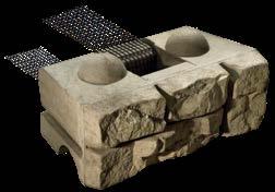
Redi-Rock blocks are designed to allow the construction of relatively tall non-reinforced (gravity) walls which use the weight of the blocks to provide stability. However, for some projects it may be necessary to build taller walls. In these cases, mechanically stabilized earth (MSE) retaining walls can be built with the Redi-Rock Positive Connection (PC) system. (Figure 16)
The geogrid used in Redi-Rock PC system walls are 12 in (305 mm) wide strips of PVC coated polyester geogrid that wrap through a vertical core slot cast into the block and extend full reinforcement length into the reinforced soil zone on both the top and bottom of the block.
Figure 15 – Running Bond Configuration
Figure 16 – Redi-Rock PC System Facing Block with 12 in (305 mm) Wide Strip of Solmax Miragrid XT Geogrid Soil Reinforcement.
INSTALLING GEOGRID FOR MECHANICALLY STABILIZED EARTH WALLS
When it comes to installing Mechanically Stabilized Earth (MSE) walls, all steps up to this point remain the same. The main difference with MSE walls is the step of including geogrid reinforcement as the wall is installed.
It is critical to only use factory cut strips of Miragrid geogrid that are certified by Solmax for width and strength. Field cutting strips of geogrid from standard rolls can significantly degrade the capacity of the wall system and is not allowed. Geogrid strips are only available through a licensed Redi-Rock Manufacturer. (Figure 17)
Verify that it is the correct geogrid material and strength and then cut the individual strips to the required length. The distance a geogrid strip must extend into the reinforced soil zone (design length) is measured from the back of the block to the end of the geogrid. Since the geogrid wraps through the block, the actual cut length of a given geogrid strip is two times the design length plus enough additional geogrid to wrap though the block. For the Redi-Rock 28 in (710 mm) PC blocks, the cut length is two times the design length plus 3 ft (914 mm).
(DL x 2) + 3 ft (914 mm)
Inspect the Redi-Rock PC blocks for any concrete flashing or sharp edges in the slot and groove through the block. Remove any flashing and grind smooth any sharp edges which could damage the geogrid reinforcement.
Place the geogrid strip in the vertical core slot from the bottom of the block and pull approximately half of the length of the strip up through the core slot. Measure from the back of the block unit to the required design length and pin the bottom leg of the geogrid strip with staples, stakes, or other appropriate methods. Pull the geogrid strip tight to remove any slack, wrinkles, or folds. Secure the geogrid firmly in place by putting a pin through the geogrid and the steel lifting insert which is located in the recessed area on the top of the PC block (Figure 18) or placing drainage aggregate in the vertical core slot.
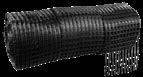
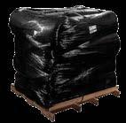
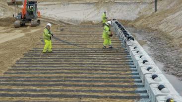
Figure 17 – Redi-Rock Geogrid Strips
Figure 18 – Remove Slack in Bottom Side of Grid
Place drainage aggregate between and behind the blocks. (Figures 19 & 20) Place the stone in uniform loose lifts as required in the project plans and specifications. Consolidate the stone between the blocks by hand tamping. Make sure to tamp stone into the ends of the groove on the bottom of the Redi-Rock PC blocks. Consolidate the stone behind the blocks with a minimum of three passes with a 24 in (610 mm) wide walk-behind vibrating plate compactor capable of delivering at least 2000 lb (8.9 kN) of centrifugal force. Provide further compaction if needed to meet the density specified in the contract documents, but not less than 85% relative density of the stone determined in accordance with ASTM D-4253 and D-4254.
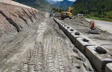
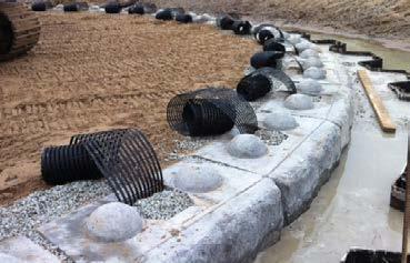
Place a strip of non-woven geotextile fabric between the drainage aggregate and the reinforced soil zone if specified. Place the reinforced soil zone material in uniform loose lifts as required in the project plans and specifications. Reinforced soil zone material must be compacted to a density as specified in the contract documents, plans, and specifications but not less than 90% maximum density as determined by a modified proctor test (ASTM D1557).
Begin compaction at the back of the wall blocks and proceed to the embedded end of the geogrid strip using care to maintain the reinforcement strip in a level, taut condition oriented perpendicular to the back of the block unit to which it is attached.
Use hand operated compaction equipment within 3 ft (914 mm) of the back of the PC blocks. Heavier equipment can be used beyond 3 ft (914 mm) away from the PC blocks. Tracked construction equipment must not be operated directly on the geogrid strip reinforcement. A minimum fill thickness of 6 in (150 mm) is required for the operation of tracked vehicles over the geogrid strips. Turning of tracked vehicles should be kept to a minimum to prevent displacement of the fill and the geogrid strips. Rubber-tired vehicles may pass over the geogrid strips at a slow speed of less than 5 mph (8 km/hr). Sudden braking and sharp turning should be avoided.
Figure 19 – Drainage Aggregate Locations
Figure 20 – Installed Drainage Aggregate
After placing and properly compacting backfill to the elevation of the geogrid strip at the top of the block, extend the top leg of the geogrid strip to the design length required. Pull the geogrid strip tight to remove any slack, wrinkles, or folds. (Figure 21) Pin the top leg of the geogrid strip with staples, stakes, or other appropriate methods to hold it in place and keep the geogrid strip taut.
Fill the center slot in the PC blocks with drainage aggregate. Be careful to keep the grid flat against the back of the slot in the PC block and prevent any stone from lodging between the geogrid and the concrete block. Fill the vertical core slot completely with drainage aggregate. Consolidate the drainage aggregate by hand tamping. Use a broom to sweep clean the top of the blocks. Do not operate a walk behind vibratory plate compactor on top of the Redi-Rock PC blocks.
Place retained soil immediately between the end of the reinforced soil zone (identified as the embedded end of the geogrid reinforcement strips) and the back of the excavation. Compact retained soil to a density as specified in the contract documents, plans, and specifications but not less than 90% maximum density at ± 2% optimum moisture content as determined by a modified proctor test (ASTM D1557). Maximum differential elevation between the reinforced fill and the retained soil fill should never exceed 18 in (457 mm).
Continue construction in a similar fashion to the top of the wall. (Figure 22)
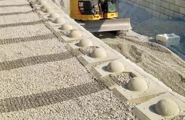
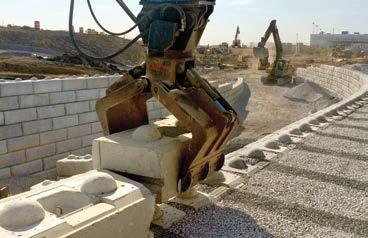
Figure 21 – Remove Slack in Top Side of Grid
Figure 22 – Continue Block Placement
XL AND 41 IN (1040MM) HOLLOW CORE RETAINING BLOCKS
The greater width of XL blocks allows gravity walls to be built to greater height, while the greater individual block heights means that each block creates more area of wall face. XL block retaining wall installation generally follows the procedures of other Redi-Rock products, with a few differences.
Following the general procedures on pages 9-16, prepare the subgrade soils and place the leveling pad. The required leveling pad thickness will depend on the design by the wall design engineer, but will generally be a minimum of 12 in (305 mm) thick.
Use appropriately-rated rigging fastened to the three lift hooks (one in the middle and two in the back of the blocks) and suitable heavy equipment to lift blocks into place. Place the first row of blocks to the correct line and grade. Just as with other Redi-Rock products, paying extra attention to ensure the first row of blocks is level and installed to the correct line and grade will save effort later as the installation proceeds.
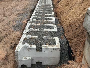
If specified, place two 18 in (457 mm) by 18 in (457 mm) pieces of non-woven geotextile fabric in each vertical joint between blocks – one on the upper half of the joint and one in the lower, wedge-shaped portion of the joint - to prevent the drainage aggregate and backfill material from migrating through the vertical joints at the blocks’ face. Place washed drainstone or open-graded crushed stone backfill into the hollow cores of the blocks and between blocks in lifts of no more than 9 in (230 mm) deep. (Figure 23) Compact each lift by tamping until no further consolidation occurs with a soil tamper or other similar method. Strike off the top and sweep the upper surface of the blocks so the next row will sit cleanly on the lower row.
geotextile at face
Nonwoven
Figure 23 - XL Block with Stone Infill
For a similar result utilizing a smaller block, the same procedure can be applied to the 41 in (1030 mm) Hollow Core block. (Figure 24) Both the XL blocks and the 41 in (1030 mm) Hollow Core block can accommodate rebar placement followed by concrete poured into the cores (in lieu of crushed stone) for additional strength if specified by the Wall Engineer.
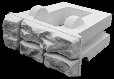
Due to the high percentage of open-graded stone within and between blocks, a drainage course behind the blocks is not required, but may be desirable to ease compaction of backfill and improve drainage. Place a layer of nonwoven geotextile fabric between the back of blocks (or drainstone layer, if used) and retained backfill. Place and compact backfill as described above and repeat as necessary to reach the required height. Finish the top of wall with one or more rows of 18 in (457 mm) high retaining blocks or freestanding blocks.
FREESTANDING WALLS
Redi-Rock freestanding wall blocks have facing texture on two or three sides. They are used in applications where multiple sides of the wall are visible. Freestanding blocks can be installed as “stand alone” walls, such as perimeter walls or fences. They can also be designed and installed as the finishing top courses on a Redi-Rock retaining wall.
Freestanding wall installation is similar to that for Redi-Rock retaining walls. The main exception is that there is typically no backfill material behind the freestanding walls. Even though there is no backfill acting on the walls, freestanding walls need to be properly engineered. They require adequate stability at the base of the wall and they need to resist any applied forces such as wind loads or forces from railings or fences. If a “stand alone” freestanding wall is being constructed, prepare the subgrade soils and leveling pad as described previously. Place bottom blocks on the leveling pad. A 6 in (150 mm) minimum bury on the bottom block is typical. Extra bury may be required for some projects. Middle and top blocks are placed directly on top of the bottom blocks with no batter.
When building a freestanding wall on the top of a Redi-Rock retaining wall, end the last row of retaining wall blocks with a middle block. The size of the knob on top of the last row of retaining wall blocks will establish the setback for the first row of freestanding blocks. Retaining blocks with a 10 in (254 mm) diameter knob will
Figure 24 - 41 in (1030 mm) Hollow-Core Block
produce a 2 7/8 in (73 mm) setback between the retaining block and the first freestanding block. If the retaining blocks have a 7 1/2 in (190 mm) diameter knob, the setback between the retaining block and the first freestanding block will be 1 5/8 in (41 mm). Be sure to contact the local Redi-Rock Manufacturer to determine availability of blocks with different knob sizes.
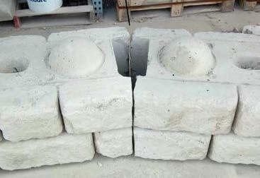
Begin and end freestanding walls with full or half corner blocks. Freestanding walls are installed plumb with no batter.
Variable radius freestanding blocks with a 4 in x 12 in (102 mm x 305 mm) pocket in one or two ends of the block are used to make curved walls. Field cut the relatively thin face texture on the ends of the variable radius blocks as needed to make the desired radius for the wall. (Figure 25)
Colored foam “backer rod” can be used to fill any small gaps which may occur between the blocks when installing walls. Backer rods can be purchased from concrete supply centers. Call the local Redi-Rock Manufacturer for help locating foam backer rods for the project.
Figure 25 – Variable Radius Freestanding Blocks
HOLLOW CORE FREESTANDING WALLS
Redi-Rock Freestanding Hollow Core units are stacked, similar to other Redi-Rock freestanding blocks, but then filled with cast-in-place concrete. Freestanding Hollow Core blocks work well for freestanding barriers, and can also be utilized for cantilever retaining walls.
CANTILEVERED WALLS
For many applications, the Freestanding Hollow Core blocks will be supported by a reinforced concrete footing. Prior to placing the footing, lay out the wall to determine the locations of the open cores in the staggered rows of Hollow Core units. This will help determine where rebar should be placed in the footing. When determining vertical rebar placement, consider the equipment that will be used to place the block to help avoid conflicts. Number and size of rebar will depend upon the engineer’s structural design.
Construct the footing on a competent subgrade per the design drawings. Once the footing has cured, use a stringline to mark the alignment of the blocks (usually the inside of the block). Begin placing blocks. A scissorstype clamp works well. (Figure 26) Alternatively, straps looped around the interior ribs can be used, as well.
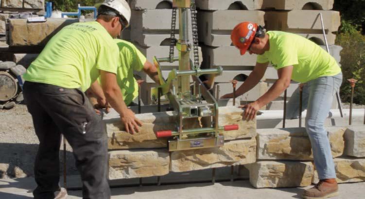
Figure 26 - Scissor Clamp for Block Placement
Corners can be constructed in the wall using Hollow Core corner blocks. These blocks have texture on three sides. For a tight fit between blocks, the texture on the corner block can be trimmed by 2 or 3 in (51 or 76 mm) where it abuts the adjacent block. If the design requires continuous rebar, cut a section out of the side of the corner block aligned with the hollow core of the adjacent block. (Figure 27)
Place continuous horizontal No. 6 rebar in the blocks, supported in the grooves on the interior structural ribs with minimum 24 in (610 mm) overlap on ends. Place vertical No. 6 rebar at 11 1/2 in (292 mm) on center, both sides of center core, lapping and tying, as required. Stack the next row of block, making sure to carefully align the blocks and staggering the joints to create a running bond. We recommend stacking no more than three courses of block without filling the core.
Prior to infilling the wall, we suggest grouting the joints between blocks with non-shrink standard grout. This helps prevent leakage during infilling, and provides an aesthetic element.
Infill the hollow core of the wall with ready-mix concrete meeting the requirements of the design. Place the concrete carefully to prevent misalignment of the rebar. While filling, use an internal concrete vibrator to ensure consolidation and eliminate voids.
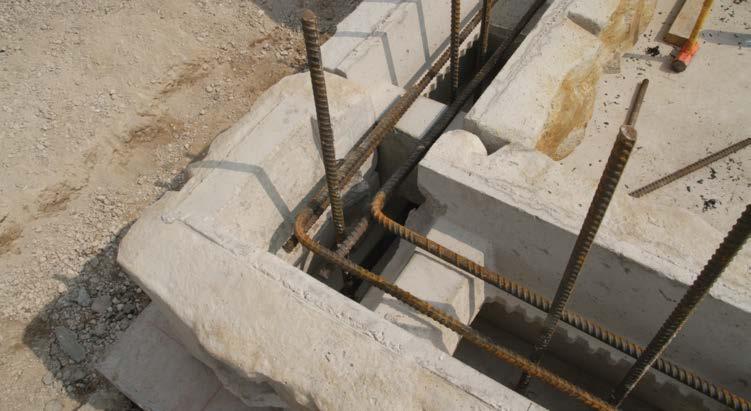
Figure 27 – Rebar in Grooves Ready for Concrete Fill
COPING
Freestanding Hollow Core blocks can be placed on Redi-Rock PC-series or 41 in (1030 mm) Hollow Core blocks to create a freestanding coping. The connection uses either a No. 3 rebar hook to tie the coping to the upper PC blocks or a No. 6 rebar connection to the upper 41 in (1030 mm) Hollow Core blocks.
Install a No. 3 rebar hook through the lifting hook in each PC block and let the hook lay on the shear knob. Install PC geogrid strips, if required. Fill the PC core with stone to the recess area. Place plastic sheeting over the geogrid exposed in the PC core.
Install No. 6 rebar in required bent formation to connection the Freestanding Hollow Core block to the 41 in (1030 mm) Hollow Core block.
Place the Freestanding Hollow Core blocks in place on the PC or 41 in (1030 mm) Hollow Core blocks. Install the horizontal and vertical reinforcing steel, as required by the design. Pull the rebar hooks up into the freestanding Hollow Core block’s core and engage with the horizontal rebar. Fill the hollow cores with concrete. (Figures 28 & 29)
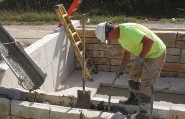
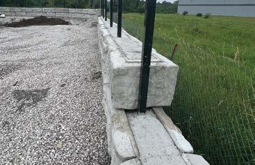
Figure 28 – Fill Hollow Core with Cast-In-Place Concrete
Figure 29 – Completed Hollow-Core Block Coping
CAP INSTALLATION
Cap units are commonly used on top of freestanding walls to provide a finished look. (Figures 30 and 31)
Mark the center of the freestanding blocks to monitor the correct running bond spacing. Secure the cap with construction adhesive appropriate for wet cast concrete in outdoor environments.
Adhesive should be applied in two rows at the top of the freestanding blocks at 8 in (203 mm) on center. Caps can be cut as needed for proper alignment. If desired, grout the joints between cap blocks after installation with a non-shrink grout.
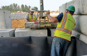
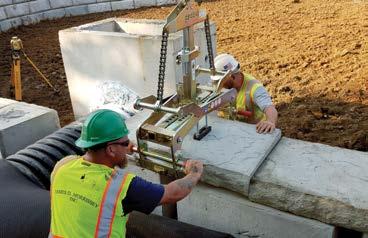
Figure 30 – Installing Cap on Retaining Block
Figure 31 – Installing Cap Using Clamp
CURVES
Few Redi-Rock walls are perfectly straight. Most walls include curves and corners to meet project requirements and improve appearance. For this reason, Redi-Rock units incorporate features that simplify construction of curved and cornered wall segments.
CONCAVE (INSIDE) CURVES
Inside corners built with Redi-Rock units are not usually limited by a strict physical minimum radius because adjacent units typically touch at only one point near the face. However, the primary concern is appearance. RediRock units are fixed in size and create a faceted curve. If the radius is too tight, the wall may look excessively faceted and unfinished surfaces or non-textured areas may become visible.
CONVEX (OUTSIDE) CURVES
The side taper of the units controls how closely adjacent units can be placed and therefore defines the minimum achievable radius. The block-to-block setback must also be included in the layout. Due to the setback, each successive course has a slightly shorter radius than the course below, similar to the inside lanes of a racetrack. Designers must select a sufficiently large base radius so that units continue to fit together properly at the top of the wall. The minimum radii depending on the number of courses is available on RediRock’s website.
RUNNING BOND IN CURVED WALLS

On both concave and convex curves, Redi-Rock units will naturally drift in and out of perfect running bond. This becomes critical where the wall:
• Turns a corner, or
• Ties into a fixed feature (e.g., building wall, end of wall, or structure).
To manage this, implement the following strategies:
1. Start at fixed points - Begin installation at the fixed feature (corner or wall end) and build away from it. Any drift from perfect running bond becomes less noticeable as the wall extends away from the fixed point.
2. Use shorter units where available - Shorter Redi-Rock units, such as half blocks, can be used to gradually bring the pattern back into running bond.
3. Field cutting as needed - If required, units may be cut in the field to achieve proper alignment. Proper planning and use of shorter units will reduce the amount of cutting needed while maintaining an attractive pattern and the required geometry.
CORNERS
Similarly to curves, corners require additional advance planning and/or specialized corner blocks to achieve a sharp, functional look.
INSIDE CORNERS
Inside corners can often be built without dedicated corner units. To do this, one wall segment is extended past the corner, and the intersecting wall is then built flush to the face of the first wall. Depending on the design, the walls may simply abut, or units may be placed so the inside corner is constructed with interlocking units for improved alignment and performance. When available, half blocks can also be used in place of abutting full blocks to create the same look.
OUTSIDE CORNERS
Outside corners typically require special Redi-Rock corner units that provide finished texture on two faces, and integrate structurally and visually with the standard retaining units. Design and construction details must consider the wall batter (in both directions), the specific geometry of the project, and any field modifications required (e.g., trimming alignment knobs or similar features). These modifications are generally acceptable when done per Redi-Rock details and do not affect structural performance.
MULTIPLE CORNERS AND GEOGRID LAYOUT
More complex configurations can be arranged to accommodate multiple corners within a wall as well as allowing for geogrid to be incorporated into corner and curve layouts. Recommended resources for selecting appropriate corner units and guidance for common corner conditions can be accessed on Redi-Rock’s website
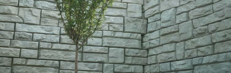
Figure 32 – Inside Corner of a Redi-Rock Wall
COLUMNS
Column blocks are available to complement Redi-Rock walls. Columns can be installed by themselves or with fences or gates.
• Column blocks can be placed on properly prepared aggregate or concrete leveling pads or directly on Redi-Rock retaining wall blocks, depending on the specific design for the project.
• Column blocks can be manufactured with pockets for concrete or split wood fence rails.
• Concrete adhesive or polyurethane sealant can be used between stacked column blocks.
• Install a cap on the top of a column. Adjust the cap position until all sides are equidistant and square to the column. Secure the column cap with construction adhesive or polyurethane sealant.
• Special inserts are available for mounting gates or similar features to Redi-Rock columns.
• Column blocks are available with 4 in (102 mm) or tapered 8 in (203 mm) diameter cores which can be filled with stone or concrete and steel rebar reinforcement.
• A conduit can be left through the core if needed for lighting or other features.
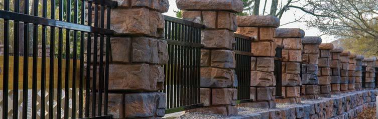
Figure 33 – Finished Redi-Rock Columns
SPECIAL FEATURES
Some walls require special features such as top of wall details, details for elevated groundwater/seawall applications, pipe penetrations and more. Refer to the construction documents, plans, and specifications for details to construct these features. Additional general reference construction details are available on the RediRock website, redi-rock.com
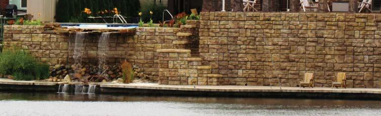
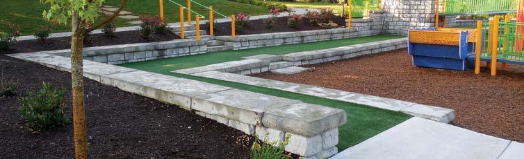
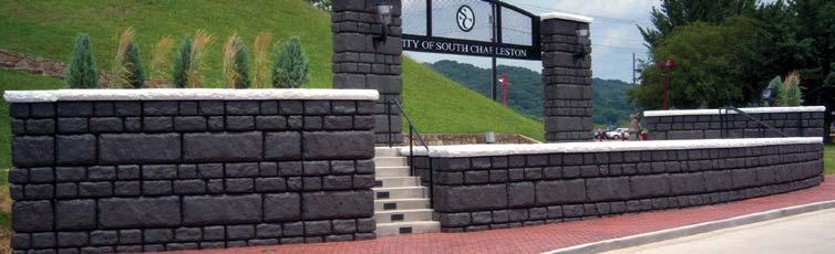
Figure 34 - Water feature part of Redi-Rock wall
Figure 35 - Turf area in between tiered walls
Figure 36 - Multi-Texture blocks as well as unique stain
IMPORTANT NOTES
Best practice dictates that wall construction should be continuous without interruption or delays on a project. This will help expedite timeline and minimize the time any excavation is open.
The construction site should be graded and maintained to direct surface water runoff away from the retaining wall throughout the entire construction process.
Do not exceed the allowable construction tolerances specified in the contract documents, plans, and specifications.
At no time should tolerances at the wall face exceed 1 degree vertically or a 1:200 ratio deviation with a maximum 2 in (50 mm) from staked location horizontally.
Immediately report the following site conditions, if encountered, to the Engineer or Owner’s Representative to determine the corrective action needed:
• Any observed groundwater seepage.
• Surface water run-off directed toward the retaining wall during construction.
• Erosion or scour of material near the wall.
• Ponded water near the wall.
• Wet, soft, or easily compressible soils in the foundation zone.
• Existing rock that differs in location from that shown on the project plans or rock located above the elevation of the bottom of the leveling pad.
• Existing or proposed toe or crest slopes that differ from typical cross-sections shown in the project plans.
• Any other items not specifically mentioned which raise questions or cause concerns during wall construction.
Immediately implement any corrective action before resuming wall construction.
Every Redi-Rock Manufacturer/Distributor is independently owned and operated.
©2025 Redi-Rock International