30 minute read
Technical

from Auto Service Professional - June 2017
by EndeavorBusinessMedia-VehicleRepairGroup
Hybrid service is not rocket science
They’re no harder to diagnose, they’re just different!
If you are turning over hybrid car repair to other shops, today’s the day to stop. Now is the time to invest in training and tools to work on these vehicles because the number of hybrids on the road is only going to grow. Make sure you can grab your share of this market by learning how to diagnose and correct the common hybrid vehicle’s service issues.
By Jacques Gordon
Most of the normal service and repair required by a hybrid vehicle is the same as other cars. They all need fluid changes and brake service, they all have oxygen sensors and EVAP systems and they use the same generic OBD-II fault codes as their non-hybrid cousins. But, of course, the hybrid powertrain and high-voltage battery add an extra layer of complexity, and most repairs for these systems require special tools, knowledge and information that are way beyond the scope of a magazine article. Most, but not all.
Hybrids are no harder to diagnose or repair than other vehicles; they’re just different. If you’re turning away customers because they drive hybrid cars, it’s time to invest in tools and training, because the fleet will keep growing and there’s money to be made. Meanwhile, here are a few common service items that are not at all difficult for experienced professional technicians with standard tools and a good service information system.
This article will focus on Toyota hybrid vehicles because they make up the bulk of the hybrid fleet.
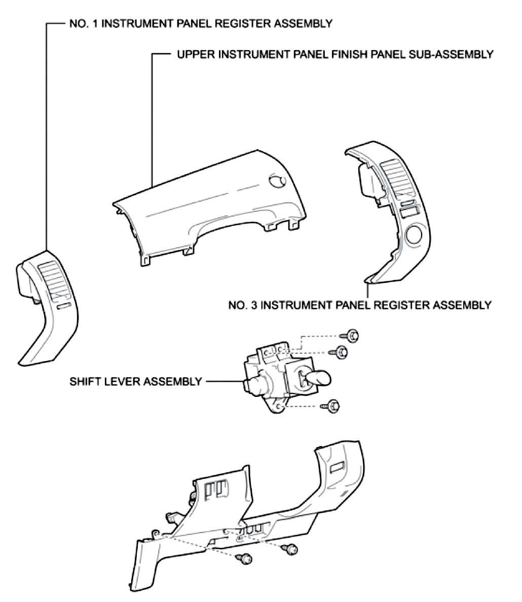
Shift lever
A common problem with the secondgeneration Prius (2004 – 2009) is a shift lever malfunction. After “starting” the car (READY light on) and shifting into gear, the transmission immediately returns to Neutral regardless of how the lever is manipulated. Often it cannot be shifted back into Park, although rebooting the car (shut-down and restart) often gets it going again. This is usually the only symptom; there will be no fault codes or warning lights on the instrument panel. The fix is simple: replace the shift lever assembly and clear the shift lever memory by disconnecting the 12-volt auxiliary battery. The job requires the removal of four dash panels, three bolts and two connectors. See Toyota TSB-0142-11 for the latest part numbers.
Auxiliary battery
On a Prius, the traction motors and the A/C compressor are powered by the high-voltage battery pack. Everything else operates on 12 volts supplied by the auxiliary battery. This is an absorbed glass mat (AGM) battery mounted in the trunk. Like regular car batteries, AGM batteries still use lead/acid

the electrolyte is absorbed into the mat. AGM batteries can deliver high current flow and they can tolerate deep discharging. They also can be sealed so they don’t emit hydrogen or acid fumes, but the charging current must be managed very carefully to avoid overheating.
The auxiliary battery powers all the control units, and the car won’t even turn on if that battery is dead. If the battery is low, the computers and control unit won’t get steady voltage and they become very unpredictable. That’s why the auxiliary battery is monitored constantly and a warning light is illuminated if it falls below 9.5 volts.
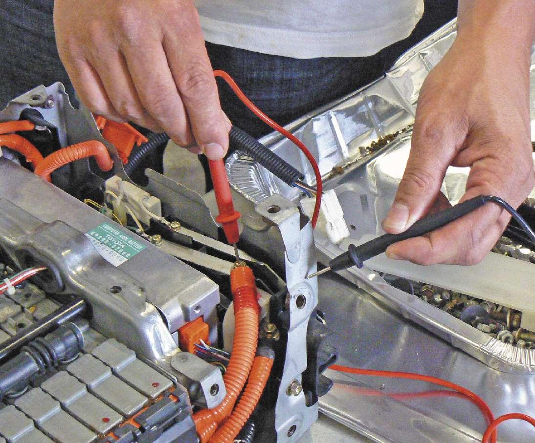
A good battery will show about 12.4 volts test battery voltage and charging voltage from the driver’s seat.
Turn the headlights on, then put the car into READY mode and look for the warning light on the instrument panel. If the infamous “red triangle” stays on steadily, check for an error message on the display screen indicating a problem with the transmission. That’s a sure sign of a failing auxiliary battery.
The warning light may not turn on or it may appear for only a few seconds, so here’s how to check the voltage:
1. Turn the car on in Accessory mode (push the power button without pushing the brake). 2. Push and hold the Display button next to the display screen. 3. Turn the headlights on The shift lever on the second generation Prius (2004 - 2009) can and off three times, and then fail without warning, leaving the car in Neutral. release the Display button. technology, but instead of plates in a bath select “Menu.” of liquid electrolyte (flooded cell), there is a 5. Select “Display Check.” fiberglass mat between each lead plate and 6. Select “Vehicle Signal Check.”
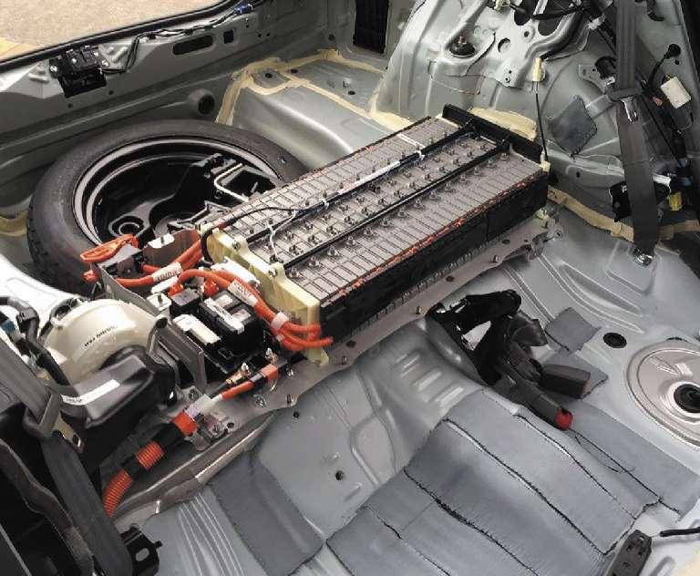
4. On the touch screen, at rest and about 10.4 volts under maximum This photo shows the location of the hybrid battery pack in a Toyota Prius third generation hyload. Since the auxiliary battery on a Gen II brid. Note that the battery cooling fan is located Prius is hard to reach, there is an easy way to on the passenger side of the battery.
While reading battery voltage on the screen, begin turning on lights and other electrical accessories to load the battery. If it drops below about 10.5 volts, the battery should be replaced. If you push the brake pedal and the power button again to go into READY mode, the battery will begin charging and you can see charging voltage: It should be about 14.2 volts even before the engine starts. Remember, the generator charges the high-voltage battery, and the voltage inverter takes power from the high-voltage battery to charge the auxiliary battery.
Hybrid drive battery
Right now there are two different battery technologies used in hybrid vehicles; nickel metal hydride (NiMH) and lithium ion (Li-ion). By 2013, most car manufacturers began switching over to Li-ion batteries because they can charge and discharge faster and they offer a higher power density (power per size/ weight). However, Li-ion batteries can overheat dangerously if they’re overcharged, so the batteries must be carefully managed with sophisticated software. Since Toyota models with Li-ion batteries are
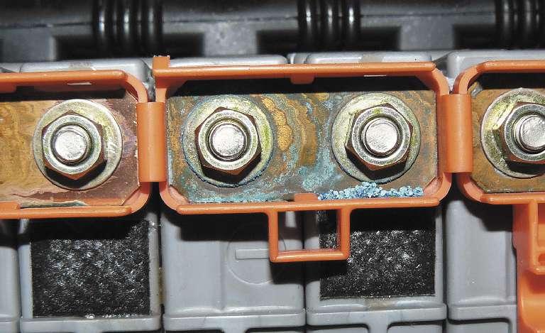
Note that corrosion at the battery module terminals can cause uneven charging and discharging that will set a battery fault code.
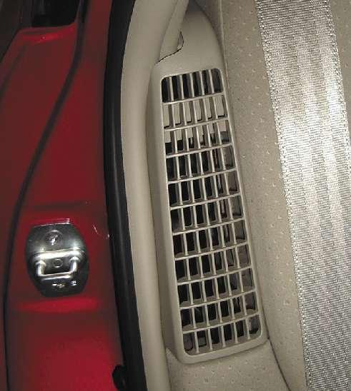
The air intake vent for the Prius battery cooling fan has no filter. The fan should be cleaned at least once a year.
still under warranty, we’ll discuss the NiMH batteries.
A high-voltage battery pack is made up of individual cells, or as Toyota calls them, battery modules. Their state-of-charge (SOC) is monitored constantly, and a fault code will be set if the PCM detects a module that is more than a few tenths of a volt different from the others (Li-ion battery modules are monitored to hundredths of a volt). A stateof-charge fault can be caused by corroded module connections or by failure of the module itself.
It’s rare for a whole battery pack to wear
Leaking electrolyte or moisture in the vehicle’s battery tray can create a path to chassis ground, setting code P3009.

out or fail completely; it’s more common for individual modules to fail the SOC monitor. That said, the individual modules are pretty hardy, and most failures are due to overheating of the whole battery pack. They also fail due to lack of use: The battery packs in hybrid taxi cabs are generally lasting 300,000 miles, which is three times the factory warranty period (or twice the California warranty).
NOTE: If there are fault codes for the engine, those problems should be fixed first. Some engine management malfunctions will make the engine run longer or more often than normal to keep the battery charged.
The PCM monitors the voltage of each cell and the current flow of the whole battery pack. It also monitors the battery temperature, and one of the most important maintenance items in any hybrid vehicle is the battery cooling system. Toyota battery packs are air cooled by a squirrel-cage fan that draws air from the passenger cabin and exhausts it outside the vehicle (the Highlander hybrid has three fans). On earlier models there is no air filter on this system, and that has caused problems over the years. Fault codes PA080 and PA07F indicate high-voltage battery failure, but sometimes those codes are a symptom of overheating and can be cured just by cleaning the fan and air ducts.

Lineman’s gloves must be worn when removing or installing the battery service plug or the battery itself. Even a pinhole is enough to render the gloves ineffective, so leather gloves are worn over the rubber lineman’s gloves to protect them from damage.
Safety note
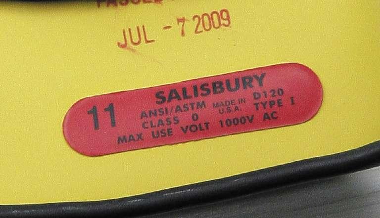
When working with the high-voltage system, the service plug must be removed to isolate the high-voltage battery. The plug is somewhere on the battery pack itself but its exact location is different on different models, so you’ll have to look it up in service information. The plug should be removed and placed on the dashboard of the car. This way everyone can see that it’s been removed and it stays with the car. When removing or installing the plug or the battery pack, wear Class 0 lineman’s gloves rated for 1,000 volts AC.
The battery modules in the first generation Prius (2001 – 2003) tend to leak electrolyte from a fill port on the module. It’s right next to the connection terminal, and it causes corrosion that can interfere with proper charging of the module and set battery fault codes. It also can provide a path from the high-voltage battery to chassis ground, which sets code P3009. Toyota launched a Special Service
Code P3009 is described as “high-voltage leak detected.” This means the PCM has detected a path from the high-voltage system to chassis ground. This can happen in the motor/ generator or in the power inverter, and you wouldn’t tackle those repairs without proper training and information. However, the voltage leak can also occur in the battery pack itself and there’s a simple way to test for this, but it requires erasing the fault codes.
With the codes cleared, turn the power on without pressing the brake pedal. This puts the car into accessory mode, which turns on the 12-volt electrical system. At this point the battery pack relays are open and the highvoltage battery is not connected to anything else on the car.
If code P3009 returns after about two minutes, the problem is in the battery pack itself. If the code returns after putting the car into READY mode, the leak is in the inverter or the motor/generator.

for retirement even if the vehicle itself has very low mileage. Reconditioned battery packs are available from aftermarket suppliers.
There are often symptoms of high-voltage battery problems before the warning light turns on. These include poor acceleration and reduced fuel economy as the engine runs longer to charge the battery. On the first drive cycle of the day, the charge indicator may fluctuate rapidly or show no/low charge.
These lineman’s gloves were tested at 5,000 volts By the time the warning light turns on, the when made in 2009, and they are returned to the engine will be running almost constantly and manufacturer each year for testing. the battery cooling fan will be operating at
Campaign to repair the leak, and the 56-page high speed all the time. service bulletin (SSC 40G) has all the instrucAs noted earlier, aftermarket battery packs tions, illustrations and part numbers needed are available. Remanufactured batteries are to complete the repair. The job is not difficult built with modules reclaimed from cores and once the battery pack is removed, but a salvage yards. To get the best performance battery pack of that vintage is probably ready and avoid setting fault codes, the modules must be tested to match their charge/discharge
Hybrid system pack fault codes capacities. It’s not hard, The Battery Control Module directly monitors the voltage of each but to reduce the posmodule. It also has sensors to monitor the current flow of the whole sibility of comebacks, battery pack and battery pack temperature. Like anything else, a fault most shops that service code indicates one of two things: a real malfunction or a faulty sensor. hybrid vehicles prefer to Here’s a short list of the battery monitor fault codes. replace a whole battery pack instead of just a few failed modules.
P0A1F Battery Energy Control Module The number of after
P0A7F Hybrid Battery Pack Deterioration market battery pack
P0A80 Replace Hybrid Battery Pack suppliers seems to be increasing, and some are
P0A82 Hybrid Battery Pack Cooling Fan well-known companies
P0A84 Hybrid Battery Pack Cooling Fan offering warranties
P0A85 Hybrid Battery Pack Cooling Fan similar to OEM replacement parts.
P0A95 High Voltage Fuse As we said earlier,
P0A9C Hybrid Battery Temperature Sensor “A” hybrid cars aren’t any more difficult to
P0A9D Hybrid Battery Temperature Sensor “A” Circuit Low diagnose or repair than
P0A9E Hybrid Battery Temperature Sensor “A” Circuit High other vehicles; they’re
P0AAC Hybrid Battery Pack Air Temperature Sensor “A” Circuit just different. The Prius transmission is easier
P0ABF Hybrid Battery Pack Current Sensor Circuit to repair than a regular
P0AC0 Hybrid Battery Pack Current Sensor Circuit Range/Performance automatic transmission,
P0AC1 Hybrid Battery Pack Current Sensor Circuit Low and often the job can be done with the unit still
P0AC2 Hybrid Battery Pack Current Sensor Circuit High in the car. Replacing a
P0AFA Hybrid Battery System Voltage Low power inverter is easier

Circle 107 on Reader Service Card

Wheel bearing tech
From TRB to Gen I, Gen 2 and Gen 3
From the older designs to the Gen 3, wheel bearings are so dependable that they are often overlooked during diagnostic checks. But they do fail, often due to moisture, which causes corrosion, and that corrosion leads to debris that accelerates bearing surface wear. When your customers complain about strange noises or trouble lights, follow these steps to replace this critical part.
By Jeff Taylor
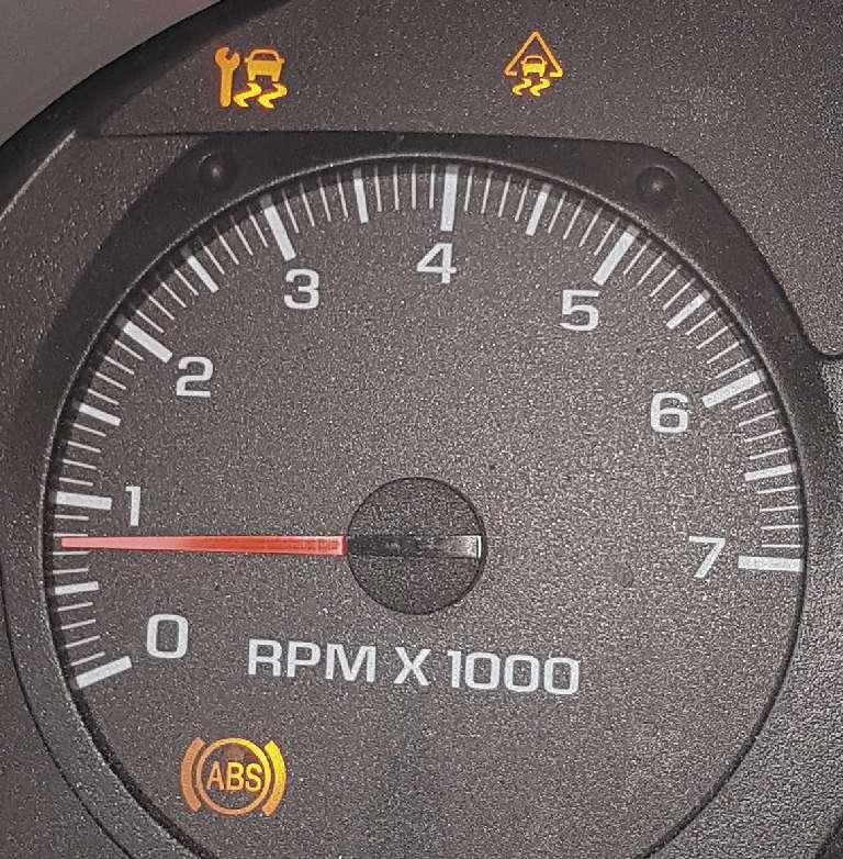
Today’s wheel bearings, like many other components, have become so dependable that we don’t pay much attention to them until there is a complaint. The typical wheel bearing grumbles are about strange noises, rumbling feelings or an anti-lock brake (ABS), electronic stability control (ESC) or traction control system (TCS) system light or issue.
A combination of these trouble lights will usually get a customer into the shop, typically before they complain hearing about any noises.
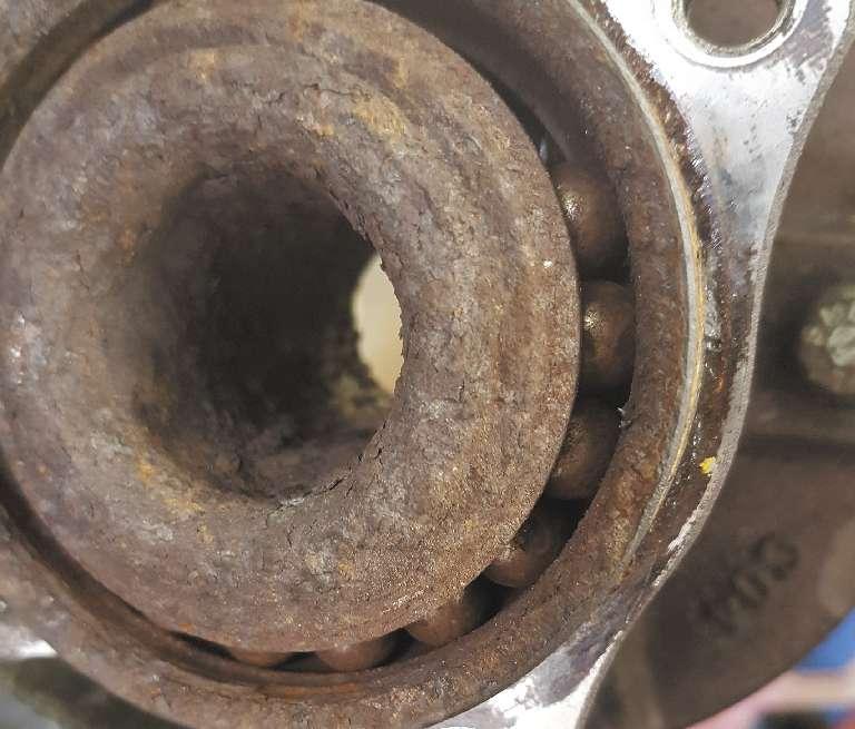
This Gen 3 bearing is so bad that the seal is gone and the balls are rusty — and some are missing.
Often the customer wants the exhaust looked at because the noise they hear gets louder the faster they drive and they translate that to an exhaust noise. Failed wheel bearings cause noises but that’s not the only concern they can cause. Repetitive brake rotor vibration failures, steering issues and strange tire wear can be attributed to a failed or failing wheel bearing assembly.
But wheel bearings are often overlooked during a diagnostic because there aren’t any of the typical wheel bearing noises associated with the complaint. Wheel bearings must deal with several forces and the loads they
generate: gravity, acceleration, braking and cornering are some of the forces and they create radial and axial loads. Road grime, brake dust, brake heat, pot holes and a myriad of other conditions are taken into consideration during wheel bearing designs allowing the average wheel bearing to spin about 75 million revolutions by the time it has travelled 100,000 miles. Even the best wheel bearing can eventually fail and when that time occurs, proper replacement procedures for the wheel bearing design used need to be followed, to ensure the same durability as the original equipment one provided.
The taper roller bearing (TRB design)
This older, but faithful style wheel bearing design is used on the non-driven front or rear wheels. The TRB was the most generic form of wheel bearing assembly used until front wheel drive became the norm.
Each TRB cone assembly consists of a tapered inner race, tapered rollers held in place by a cage and the cup or outer race. TRBs don’t have any integrated seals and are more expensive to produce then ball bearings. Used in pairs as an inner and outer cone unit, the TRB is much better at dealing with any small imperfections in alignment or fit and deals with the axial loads placed on the bearing surface better than a deep groove double ball bearing assembly.
The TRB was often just serviced if brake rotors were being replaced, but the TRB does require regular service due to moisture intrusion and grease breakdown. Cleaning and repacking TRBs that aren’t noisy, rough feeling, showing any rust or other issues, can be done by forcing the old grease out with new grease, or a solvent can be used.
When forcing in the new grease, pay attention to the color of the grease coming out to ensure that only the new, fresh grease is surrounding the rollers. And if a solvent is used, care must be taken to remove all traces of solvent before new grease is installed. The proper manufacturer-specific grease is also important, and so is the condition of the hub’s seals. If the TRB assembly has been leaking grease, this is an indication the seals are worn out, not only allowing grease out, but moisture and other contaminates in.
Moisture is the bearing’s enemy: it causes corrosion, and that corrosion leads to debris that accelerates bearing surface wear. Proper bearing preload is also vital to the TRB. The TRB needs to be set first by tightening the spindle nut to the proper torque, then the specific manufacturer’s procedure must be followed carefully before the cotter pin or retaining device is installed. The average TRB-equipped car or pickup was torqued to around 12 ft.-lbs., but some large truck applications can be a much as 400 ft.-lbs.
The Gen 1 wheel bearing design
The Gen 1 is commonly referred to as a cartridge-style wheel bearing or hub bearing. The Gen 1 features a double-row angular contact bearing assembly. The Gen 1 became a preferred bearing choice for small and medium front-wheel-drive wheel applications, but have also been used on some non-driven wheels in an integral bearing/brake drum/ hub assembly.
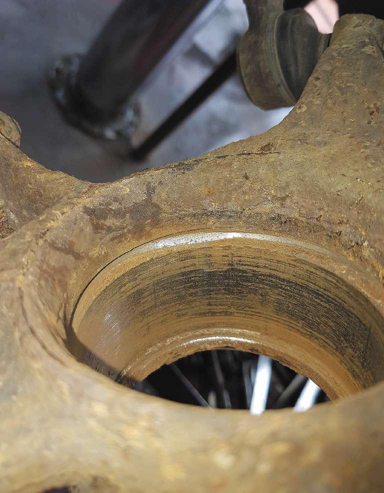
After removal of the Gen 1 bearing, the knuckle must be cleaned of all debris and attention must be paid to the snap-ring retainer groove.
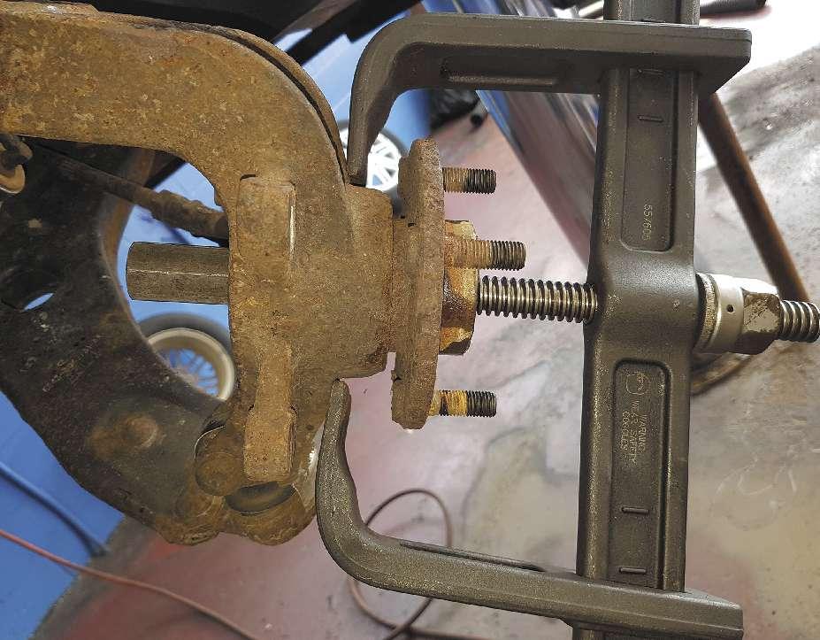
Hub tamer removing a flange on a Gen 1 bearing.
The Gen 1 assembly is composed of a single outer race, two separate inner races, bearing cages and typically ball bearings (tapered bearings can be use in tight space applications). The Gen 1 is also sealed and lubricated for life at the factory. The Gen 1 bearing delivers adequate support to deal with induced axial and radial loads that are transferred through the front wheels, especially when turning. The Gen 1 may also incorporate an impulse/ encoder ring, which is integral to the outer seal. This impulse ring provides wheel speed information to the ABS, TCS or ESC systems.
Replacement of a Gen 1 bearing can be challenging and labor intensive. The use of specialized tools to facilitate replacement is a must due to the interference fit nature of this style of bearing into the knuckle assembly. A hydraulic press can be used if the knuckle is removed or a hub tamer tool can be used for on-the-vehicle service. The flange (wheel hub) will have to be removed from the old bearing and care must be taken to make sure that it isn’t damaged or bent in the process. Slide hammers can easily distort or crack the flange, but they can and are used with proper care.
Remember not to use the actual vehicle’s wheel nuts to hold it to the flange, as they can be damaged and subsequently may not seat properly against the wheel.
Flange removal is one area where a hub tamer kit really shines. It will remove the flange safely, easily and with reduced effort. But even when using a hub tamer, press or slide hammer, typically one inner race will remain attached to the flange. This inner race has to be removed without damaging the machined surface underneath it. The use of a puller works, but I have found that a small zip cut and a chisel usually make it split with no damage to the flange or the machined mating surface. Many bearing manufacturers will tell you that it is best to install a new flange as they are often already bent or cracked from hitting curbs and other road-related injuries. After the flange is removed, the snap ring retainer (if used) will need to be removed, allowing the bearing to be pressed or pulled from the knuckle. Next, the knuckle and flange need to be cleaned and inspected, paying attention to the retainer ring groove and the seating area before any reassembly starts, as trapped debris can result in premature bearing failure.
It is also imperative to make sure that the bearing is facing the correct way before installation, if it has an encoder ring built into
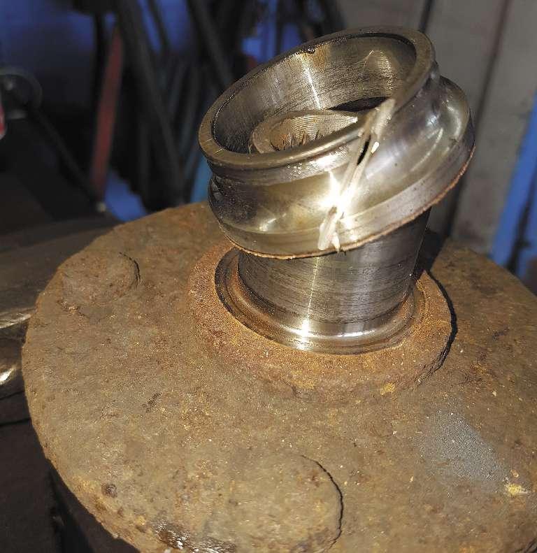
A special puller can be used to remove a stuck inner race, but I use a small zip cut and a chisel to make it split with no damage for easier removal.
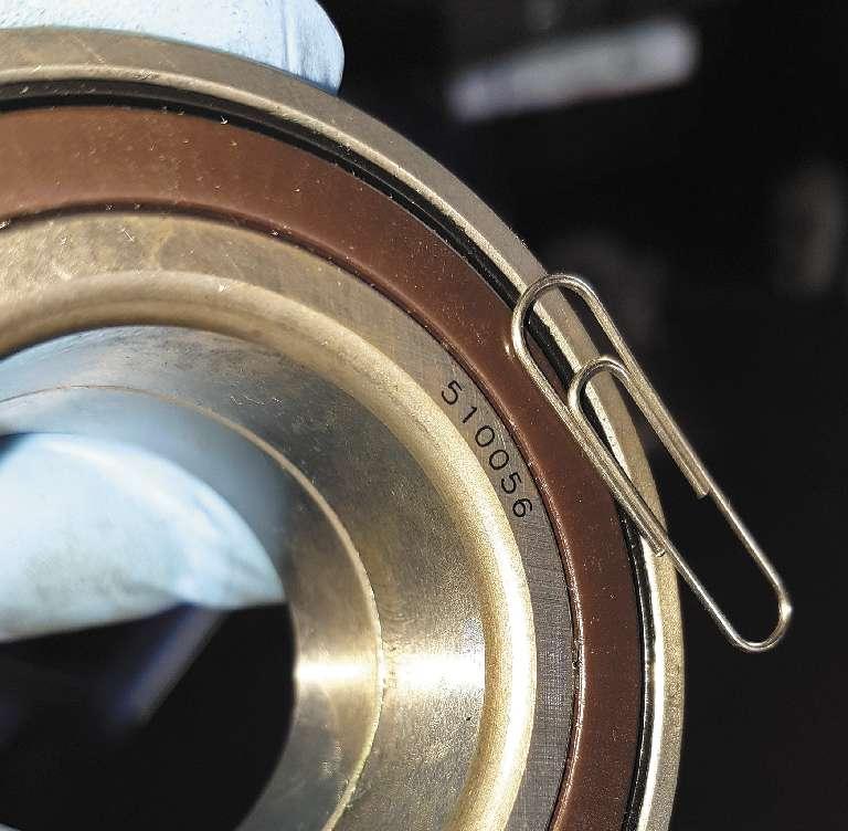
I have found that putting a paper clip on the magnetic encoder ring will help you to orient the seal toward the ABS sensor. its inner seal. I have gotten into the habit of putting a paper clip on the encoder ring (it’s magnetic), making sure that I am assembling it in the correct manner with the encoder ring facing the ABS sensor. With the bearing encoder ring properly oriented and set square or straight to the knuckle, reassembly can begin. The new bearing must be pressed on the outer ring and not to the inner ring, or bearing damage can result. If it doesn’t start in straight, you must stop and reposition it or bearing damage will result.
Over-pressing into the knuckle can also cause damage. It just needs to be seated against the inner retainer area. After seating the bearing, a new snap ring retainer should be reinstalled into the clean retainer groove. Once the snap ring is installed, it is time to reinstall either a new flange or the carefully inspected old flange.
When installing the flange, the opposite side of the bearing must be supported to prevent the bearing from coming apart and again causing damage. The last step is to properly torque a new axle nut to the correct manufacturer’s specifications using a torque wrench... not an impact gun. The Gen 1 and other bearings are susceptible to damage from the use of an impact gun, both from tightening the axle nut and during the installation of the bearing into the knuckle without the proper tools. Industry experts stress that the leading cause of premature Gen 1 bearing failure is the failure to properly torque the axle nut, even after careful installation.
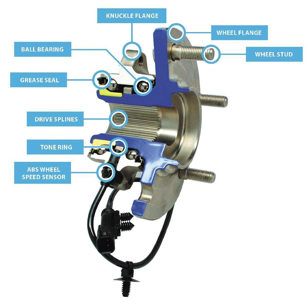
The Gen 2 wheel bearing design
The Gen 2 wheel bearing design uses a greased and sealed-for-life double row angular contact ball bearing set comparable to the Gen 1 design, but the outer race is now integrated into the flange on the Gen 2 design. This integration lowers the weight of the bearing assembly, something the manufacturers favor as they continually look for ways to reduce vehicle weight. The flange will have the spigot or pilot to locate the rotor/drum/ wheel assembly, the studs or threaded holes to attach the wheel and, if needed, an ABS tone ring or encoder imbedded inner seal. The Gen 2 wheel bearing assembly can be found on the non-driven front wheels or on the non-driven rear axle of a vehicle. It will be mounted to a machined spindle, and held in position by a retaining nut.
Repairing or replacing a Gen 2 wheel bearing can be straightforward and normally requires the removal of the rotor, caliper bracket or the brake drum, dust cover and the axle retaining nut. Occasionally a slide hammer or puller may be required to remove the assembly, but care must be taken not to damage the threads on the spindle or the spindle itself.
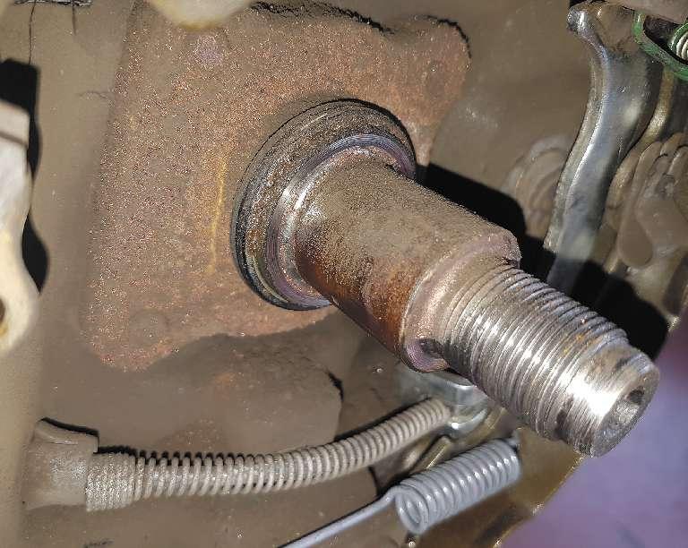
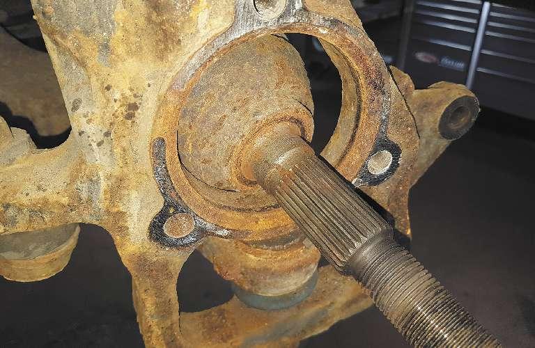
This spindle used to hold a Gen 2 bearing drum assembly needs to be cleaned with some fine emery cloth before reassembling.

When reassembling, all the mating surfaces reassembly, a new axle nut and dust cap are and the spindle should be cleaned and lubed required by most manufacturers. Again, don’t with the recommended lubricant, typically a be tempted to use an impact gun. A torque small amount of engine oil. wrench must be used to properly tighten the
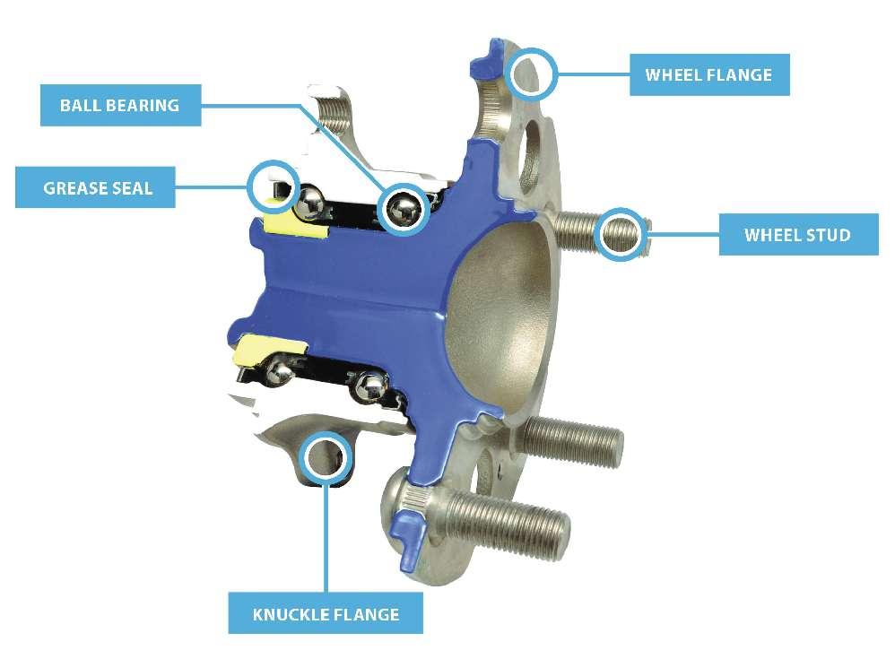
It’s important to note that never-seize lube axle nut to the manufacturer’s specifications should not be used, as it may interfere with to prevent premature wheel bearing failure. the bearing seating properly and the proper axle nut torque may not be achieved. During The Gen 3 wheel bearing design The Gen 3 wheel bearing design incorporates two separate flanges and a double row angular contact ball bearing design that are sealed and lubed for life. The use of two flanges simplifies suspension and knuckle design and creates a compact unit. The outer flange doesn’t rotate and is attached to the knuckle or suspension via a machined surface with mounting provisions (bolts or threaded holes). The inner rotating flange will incorporate the spigot and the threaded holes or studs to locate and retain the wheel. The Gen 3 unit is used in both driven and non-driven applications, but if it is being used on a driven-wheel application, the inner ring will now have splines to transfer torque to the wheel from a splined driveshaft. A sensor for the TCS, ESP or ABS systems may also be incorporated into the design of the Gen 3 unit. Servicing a Gen 3 unit requires removing the necessary brake parts and pieces and in some cases the axle shaft to gain access to the hardware retaining the inner flange to the suspension or knuckle. There are several tools available to remove these units if they have become frozen or seized to their mounting surface. Care must be These are cutaway illustrations of Gen 3 wheel bearing assemtaken not to damage the mating blies. The lower image has an ABS sensor, and they both show surfaces involved, especially inner and outer flanges and a double row of ball bearings. the knuckle or the spindle, with

The knuckle’s mating surfaces need to be cleaned to remove all the rust and corrosion before the Gen 3 hub unit is bolted on and torqued. the use of composite lightweight alloys and materials.
Before installing the replacement unit, the mating surfaces should be clean and free of any rust, debris, nicks or defects. When installing the new hub assembly onto its mounting surface, it is critical that it is aligned and seated properly and that any torque-to-yield fasteners involved are replaced before being torqued to the manufacturer’s specification. If an axle nut is used it must also be properly torqued again without the use of an impact gun.
Like the Gen 1 and 2, the Gen 3 is susceptible to improper torqueing of the axle nut if an impact gun is used.
Doing it right the first time
The use of a double row angular contact bearing assembly has become the norm. They require less space, are cheaper, allow for simplified suspension design and can deal with the axial and radial loads that are placed on them. However, they can and do fail and will need replacement.
A range of factors can cause a wheel bearing failure; age, curb contact, moisture intrusion, oversize tires, worn suspension components, out-of-balance wheels, and the operating conditions of the vehicle, to cite just a few examples. But today’s sealed wheel bearings are durable and some aftermarket bearing suppliers have even developed specialized Gen 3 bearing assemblies for SUVs and trucks to improve the initial design. Their revised design uses a larger diameter outer bearing
Note the wheel mounting stud holes, the rotor retainer and the spigot or pilot that allows wheel and rotor centering. containing more ball bearings compared to the inner bearing.
This design creates a stiffer unit that offers several benefits; it reduces NVH (noise/ vibration/harshness), increases brake rotor life due to lower lateral flange runout, and improves the vehicle’s steering/handling characteristics.
But even the best replacement wheel bearing can fail prematurely if a torque wrench isn’t used on the axle nut to set the proper bearing end play and preload. But proper torque isn’t the only essential to proper bearing replacement. Debris-free surfaces, proper bearing orientation, proper tools for removal and installation, the replacement of required fasteners and the careful attention to the routing of ABS harnesses will prevent comebacks and contribute to a successful repair. ■
I would like to thank Neil Hogan of SFK USA Inc. and Matt Gorski of NTN Bearing Corp. of America for their help and contributions in preparing this article.

Jeff Taylor boasts a 32-year career in the automotive industry with Eccles Auto Service in Dundas, Ontario, as a fully licensed professional lead technician. While continuing to be “on the bench” every day, Jeff is also heavily involved in government focus groups, serves as an accomplished technical writer and has competed in international diagnostic competitions as well as providing his expertise as an automotive technical instructor for a major aftermarket parts retailer.
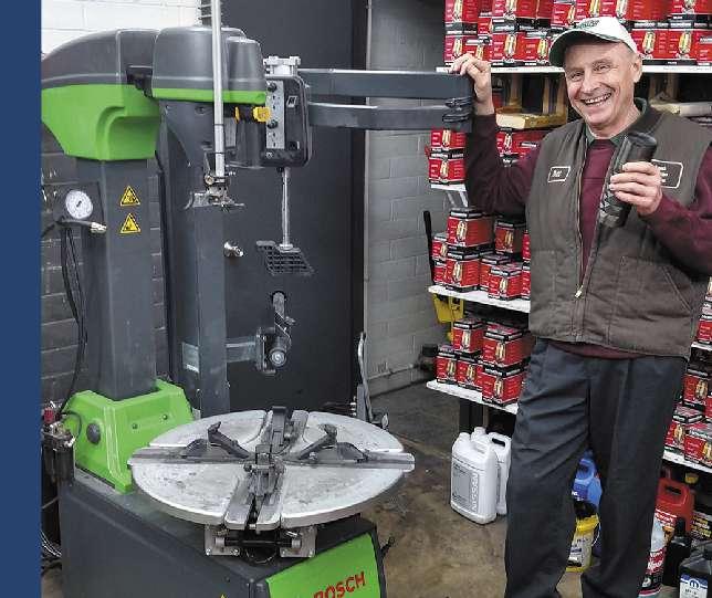
Mad Hatter Auto Service
A progressive and successful shop in Cedar Falls, Iowa
Located in the southeast area of historic Cedar Falls and immediately northwest of neighboring Waterloo, Iowa, the Mad Hatter Auto Service shop’s market area encompasses the northeast section of the state.
Why is the shop named “the Mad Hatter”? As owner John Lappe explained, “That’s a long story. Back in the day when the shop was only an exhaust shop, my understanding is that it was part of a franchise called Mad Hatter Exhaust. While that franchise tie-in no longer applies to us, we simply decided to keep the name because it was so well recognized in our marketplace.”
Editor’s note: I think that the name is also a very cool choice. For those of you who might be interested in its origin, the phrase “as mad as a hatter” refers to the use of a mercury-based compound employed in the manufacturing of fine hats during the 1830’s early Victorian period. Because of the long-term exposure to the chemical, hatters would develop tremors and mood swings, making them appear “mad” to others. Also, the fictional character the “Mad Hatter” in the iconic Alice in Wonderland book by Lewis Carroll was admittedly a bit on the whacko side.
In stark contrast, the techs at the Cedar Falls shop are far from “mad.” The staff is Mad Hatter Auto Service Cedar Falls, Iowa
Owner : John Lappe
Business founded: 1978 (under current ownership, 2000)
Number of bays: 3 Number of certified technicians: Shop size: 2,300 square feet 3 Number of vehicles serviced per month: 250 Labor rate: $98/hour Average job ticket price: $350 Gross profit: approximately 51% Average spent on tools and equipment annually: $10,000 Vehicle makes serviced: all

highly recognized in their market for their (quite sane) professionalism, prompt and quality service, as the shop has gained quite a loyal following of repeat customers.
Does your shop offer general auto repair or do you tend to specialize?
John notes Mad Hatter performs all types of general repairs, diagnostics and vehicle maintenance. Originally, the shop offered only exhaust work, but since he assumed ownership he’s expanded into a full-service operation. However, they continue to offer a full range of exhaust system work, from direct replacement to full-custom in stainless steel systems.
What is your business philosophy?
First and foremost, John says they don’t hard-sell or use scare tactics. There’s plenty of work to be had by recommending and performing work that is actually needed, John says. “We strive to educate and inform our customers prior to and after the job. We emphasize that maintenance is key in order to avoid problems. We also take advantage of email and text messages to keep our customers informed.”
Where do you buy your parts?
The vast majority of our parts are purchased from U.S. AutoForce, IWI Motor Parts, Arnold Motor Supply and OE dealers, John notes. He also will buy Mad Hatter owner John Lappe.
from a local O’Reilly’s Auto Parts in those instances when his regular sources don’t happen to have what he needs in stock. “With our computerized order entry system, we can quickly check inventory at U.S. AutoForce and IWI without even picking up the phone, which saves us time and avoids incorrect parts ordering.”
What influences your parts buying decisions? Rank from 0 to 3, with 0 having no influence and 3 having the greatest influence:
Price Brand name recognition Promotion in racing Perceived quality Availability/time 1 1 0 3 3
What do customers want/expect from your shop?
Our customers rely on us to provide accurate estimates, work performed in a timely manner, and above all, to provide quality work, John says. “Customers in our market know that they will be appreciated and treated like a person, not just a customer.”
What is your approach to training?
“We take advantage of most opportunities... supplier-sponsored training is always great. Our technicians are always on the lookout for enhanced training opportunities to keep them up-to-date on new vehicle technology, factory recalls, diagnostic upgrading, etc.” How Auto Service Professional maga
zine benefits your business:
“Auto Service Professional is a great source to read about emerging trends and shop practices. We also find that it’s a great place to learn about new tools and equipment, which helps to keep us up-to-date.”
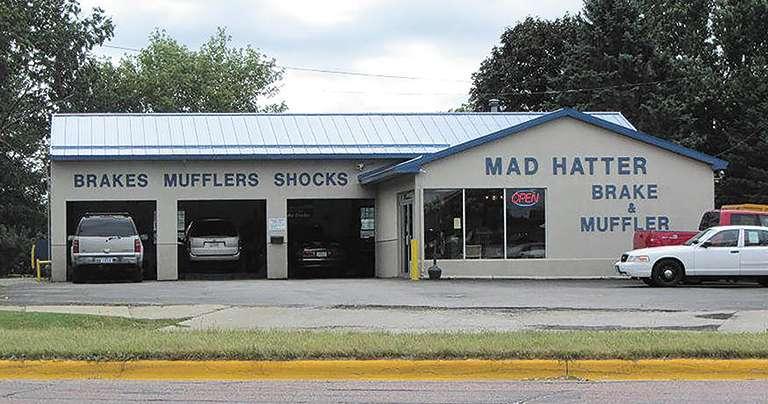
The catchy Mad Hatter Auto Service name is well recognized in Cedar Falls, Iowa.
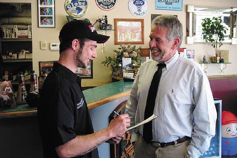
Mad Hatter has gained a very loyal following in its market. ASE technician Brette Smith chats with one of many of the shop’s repeat customers.
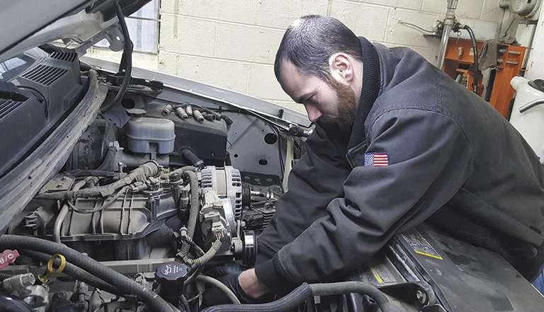
The shop handles all aspects of automotive service, and is known for their diagnostic skills. Pictured is ASE technician Blake Smith.