Arshad Khan Professional Portfolio
PAGE HAS BEEN INTENTIONALLY LEFT BLANK
Note:
1. This portfolio only gives snippets of details from the projects to give the viewer an understanding of the skills in the areas of documentation, detailing, accessibility, compliance etc.
2. Some project details have been intentionally hidden to protect project details and intellectual property.
No. Project Page 1. Apartments at Liverpool 01 2. Multi-Residential at Bellevue 05 3. Mixed Use at Marrickville 09 4. Multi-Residential at Camden 14 5. Affordable Housing at Bellingen 19 6. Seniors Living at Gilead 22
Contents
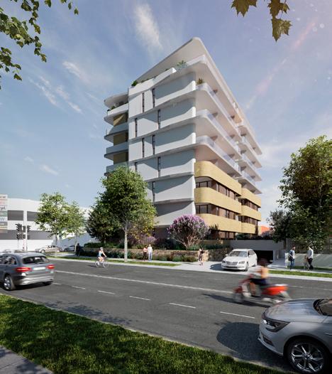
Liverpool Apartments at Liverpool, NSW.
Company: Benson McCormack Architecture
Role: CC Package (Full)
Information Displayed : 1. Ground Floor Plan
2. Concrete Setout Plan
3. Pre-Post Adaptable
Property of BMA
01
Floor Plan Apartments at Liverpool with 8 levels, roof garden and serviced with 3 basements for car parking. Consists of single, double and dual key apartments.
GSPublisherVersion 1782.1.1.27 BALC 8 m BALC 11 8 m2 BALC 12 1 m BALC 11 4 m BALC 11 m 10 11 12 13 14 15 16 17 18 19 10 11 12 13 14 15 16 17 17 R 182 16 G 250 10 13 14 15 16 17 17 R 182 16 G 250 1 2 3 4 5 6 7 8 8R 185 mm 7G 250 mm CPEX 300 650 GEX ELEC s s S 1 15 COMM FH GC FH HYD HYD HYD HYD HYD HYD HYD HYD HYD HYD HYD HYD HYD HYD HYD HYD RWO RWO BFW BFW BFW BFW RWO RWO RWO RWO JP invert 17 660 GSIP invert 17 343 PDO PDO PENO PENO BALC 8 9 m 1 15 1 510-001 1 510-002 W W W W 6,598 3M PROTECTION ZONE 4,570 7,625 7,010 2,000 7,010 7,625 4,570 4,477 2,960 4,600 1,610 6,835 3,285 2,210 5,380 1,850 301 5,500 954 1,100 2,500 FFL 19,855 FFL 18,318 FFL 18,344 FFL 19,798 FFL20,249 LID 18.300 FFL 19,897 FFL 19,897 FFL 20,062 FFL 20,062 FFL 19,765 FFL 19,793 FFL 19,970 FFL 19,830 HP19,813 LP19,783 SSL 20,035 A 130-001 D 130-004 D 130-004 E 130-005 E 130-005 F 130-006 F 130-006 B 130-002 C 130-003 WS1 530-001 WS 530-008 WS 530-003 s 530-009 WS 4 530-007 WS 530-006 TGSI TGSI TGSI EWIS FIP HATCH HATCH HATCH INTERCOM AREA ADJACENT TO DRIVEWAY TO BE KEPT CLEAR OF OBSTRUCTIONS TO VISIBILITY SHOWN HATCHED POWER POLE TO BE REMOVED AND CABLING INSTALLED UNDERGROUND POWER POLE TO BE REMOVED AND CABLING INSTALLED UNDERGROUND 2X SEATING BENCH TO COUNCIL S PUBLIC DOMAIN MASTERPLAN 1X RUBBISH BIN TO COUNCIL S PUBLIC DOMAIN MASTERPLAN 1X MULTI-FUNCTION POLE TO COUNCIL S PUBLIC DOMAIN MASTERPLAN G66Q G66Q W66O G65J G 65 T G66 G66 W 66 R W 66 R W 66 L W 66 K G 65 V G 65 R G65A W 66 R W 66 R W 66 W 66 G G65A W66X W66X W66 W66X W66X W66W W66X G65F W66W G 65 R W66O 2 02 2 01 202 3 05 5 00 6 04 BELOW 1 00 1 00 1 00 1 00 1 00 1 00 1 00 3 03 1 02 3 00 3 01 00 3 01 1 01 01 01 5 00 6 20 6 04 2 02 3 04 04 1 00 00 1 00 3 03 04 2 02 6 20 5 00 6 20 04 2 01 2 02 2 02 2 02 5 00 BELOW 1 00 00 00 02 00 00 3 00 1 00 1 00 00 1 00 1 00 00 1 00 01 04 3 04 00 04 3 05 3 03 1 00 3 04 3 04 04 3 01 6 04 BELOW 1 00 C 20 2 01 2 01 3 03 3 05 3 03 20 5 02 1 00 1 00 00 D10A 70 D 70 A D70A D 31 B D 31 A D 73 A D72A D 71 A D72 D72A D 71 A D72A 73A D 72 A D73A D 72 A D 72 A D71 73A D71A D 70 A D70 D70A D 71 A D 71 A D C D 71 C EFN1 EFN FRL-/90 90 FRL-/90 90 FRL90 90 90 FRL 90 90 90 FRL90 90 90 FRL90 90 90 FRL 90 90 90 FRL -/ 90 90 FRL-/90 90 FRL-/90 90 FRL -/ 90 90 FRL 90 90 90 FRL 90 90 90 FRL-/90 90 FRL 90 90 90 FRL 90 90 90 FRL90 90 90 BELOW 00 WF-CN03 WF-CN03 WF-CN03 WF-CN02 WFCN 02 WF-CN02 WFCN 02 01 3 01 3 00 BELOW 1 00 VI VI PUSH TO EXIT PUSH TO EXIT LVS 1 LV-F D86A D10 EFN2 EFN4 PLANTERS - REFER LANDSCAPE ARCHITECT S DRAWINGS LINE OF AWNING OVER CONCRETE PAVING - EXPOSED AGGREGRATE FINISH TO COUNCIL S PUBLIC DOMAIN MASTERPLAN VERGE GARDEN/ RAINGARDEN TO COUNCIL S PUBLIC DOMAIN MASTERPLAN NEW KERB ALIGNMENT TO COUNCIL S PUBLIC DOMAIN MASTERPLAN AND ENGINEER DETAILS FOOTPATH PAVING TO COUNCIL S PUBLIC DOMAIN MASTERPLAN EXTENT OF PUBLIC DOMAIN WORKS 34B LV- 1 LV-L 6 06 6 06 4 01 4 01a EXTENT OF PUBLIC DOMAIN WORKS SLAB EDGE LOUVRE IN RETAINING WALL FOR STAIR PRESSURISATION LVA 40 41 M / 278 ° 55 ' 00 40 41 M / 278 ° 56 50 " 33 205 M / 188 ° 55 ' 00 33 23 M / 188 ° 55 00 4 66M 23° 55 ' 20 " 466M 53°55'50 " 4 66M 83° 56' 20" SITE AREA - 1322 0 M ² LOT 2 / DP 214924 LOT 2 / SP 49087 17 5 % @ 2 0 M 1 4 % @ 2 8 M 1 20 @ 6 0 M AHD 18 02 AHD 17 70 AHD 18 3 2 9 GATE PERGOLA OVER FS2 1 200 S P LY 0 1 BT 0 5 BT 0 2 S S LY 0 1 BT 0 5 LY 0 S LY 0 P L 01 L 02 FS 2 1 40 fall 1 40 40 40 1 40 FS 3 FS 1 FS 4 K 03 K 03 D S S S K 02 D BT 1 LY S S K 02 L BT 1 LY 1 K 01 D K 01 S 1 : 40 fall 1 40 fall 1 40 fall GRASS DECK REFER PUBLIC DOMAIN DOCS FOR CROSS OVER LEVELS **REFER PUBLIC DOMAIN DOCS FOR PAVEMENT LEVELS AND DETAILS REFER PUBLIC DOMAIN DOCS FOR PAVEMENT LEVELS AND DETAILS AHD 18 32 6 AHD 18 3 47 fall BT 0 BT POS A 21 7 m POS A 44 5 m POS A 72 4 m POS A 18 5 m POS A 13 5 m2 POS A 27 m 45 0 m2 E 1 120003 S 120-002 W 1 120004 N1 120-001 13 15R 183 mm) 14G 250 mm SPEX HYD HYD HYD HYD FW FW C C B B A A 3 3 6 6 5 5 E E F F 4 4 1 1 2 2 D D 7 7 TEX CWEX HYD W W W W RWO RWO HYD HYD HYD HYD HYD RWO RWO RWO RWO RWO SPS FW FW FW FW FW FW FW FW FW FW FW FW CPSUP FW FW FW FW PDO PDO PDO RWO RWO PDO PDO PDO RWO RWO PDO PDO PDO PDO PDO PDO PDO PDO PDO PDO PDO PDO PDO PDO PDO PDO PDO 1 RAMP A-2020 2 510-001 2 510-002 3 510-001 601-040 601-040 3,000 FFL 19,089 240L 1 00 00 04 3 03 3 03 3 03 1 01 1 01 1 02 04 1 00 3 01 3 03 3 04 05 6 20 D40A D40A D 73 A D73A EFN EFN1 EFN1 EFN1 FFN FFN1 FFN1 FFN1 FFN FFN FFN2 FFN2 FFN2 FFN3 FFN FFN FFN FFN3 FFN3 FFN2 FFN FFN3 FFN3 FFN3 FFN FFN3 FFN FFN2 FFN2 FRL 90 90 90 WF-CN03 EFN1 D32B 33B EFN3 EFN3 FFN1 FFN1 6 21 6 21 6 21 6 21 OUTLINE OF VOID IN AWNING SUBSTATION GROUND LEVEL LETTERBOX E S S S STY STY 106 1B 49 9 m 104 1B+ 56 1 m 103 1B+ 56 1 m 101 1B 49 m A C A C A C A/C 105 2B 79 m 102 2B 79 m OSD 14 9 m V 24 1 m RWT 3 m ZV 6 m A/C BED 2 A 4 m2 FFN1 BED 1 A 10 3 m FFN1 BED 2 A 4 m2 FFN1 BED 1 A 10 3 m2 FFN1 BED 1 A 10 m FFN1 BED 1 A 10 m FFN1 BED 1 A 10 3 m FFN1 BED 1 A 10 3 m2 FFN1 8 8 LEGEND AC Air Conditioning ACC Accessible ADG Apartment Design Guide ADP Adaptable AH Access Hatch AHD Australian Height Datum AMB Ambulant AP Access Panel AWN Awning B1,2 Bedroom BL1,2 Balustrade BALC Balcon BG Box Gutter BGS Boom Gate System BKP Bicycle Parking BKS Bicycle Storage BLK Blockwork BRWO Balcony Rain Water Outle BT Bathroom BK Brickwork CBF Concrete Broom Finish CEA Concrete Exposed Aggr Finish CFC Compressed Fibre Cement CFF Concrete Float Finish CGF Concrete Groove Finish CHS Circular Hollow Section CIS Cister CJ Construction Joint CL Centre Line CLD Cladding CLNR Cleaner Store CMR Cement Rende CN Concret COL Column COMS Communications Services COS Check on Site CP Carparking Space CPD Cupboard CPEX Car Park Exhaus CPT Carpet CS Ceiling Suspended CSF Cementitious Screed Finish CST Concrete Steel Trowel Finish CTWF Ceramic Tile Wall Finish CWB Car Wash Ba CWS Cold Water Supply CY Courtyar D Dining DB Distribution Board DG Drip Groove DP Down Pipe E Entry EFN 1,2 External Floor Finish ELEC Electrical Services EM Entry Ma EN Ensuite EX Existing EXH Exhaust F Fire Services FCC Fire Control Centre FCL Finished Ceiling Level FCR Fire Control Room FEP 1,2 Fire Egress Passage FES Floor Edge Strip FEX Fire Extinguisher FFL Finished Floor Level FFN 2 Finished Floor FH Fire Hydran FHR Fire Hose Ree FIP Fire Indicator Panel FLS Flashing FMP Fire Mimic Panel FN 1,2 Furniture Type FRL Fire Resistance Level FS 1,2 Fire Stair No 2 FW Floor Waste GBC Garbage Chute GBR Garbage Room GDR Grated Drain GEX Garbage Exhaust GHR Garbage Holding Room GL Ground Line GPT Gross Pollutant Trap GR Grab Rail GTR Gully Trap GVL Gravel HC Hose Cock HD Hand Dryer Electric HMR High Moisture Resistanc HP High Point HR Handrail HWS Hot Water Service HWU Hot Water Unit HYD Hydraulic Service ID Inside Diameter IL Invert Level INS Insulation IO Inspection Opening 1,2 Joinery Type etc K Kitchen KB Kerb 1,2 Lift No Living LP Low Point LRA Lobby Relief Air LSA Lobby Supply Air LY Laundry LV Louvre M Mechanical Services MATV Master Antenna TV MBP Motor Bike Parking MBX Mail Box Assembly MV Mechanical Vent MVJ Movement Joint MR Mirror MSB Main Switch Board MTR Meter NGL Natural Ground Level NOM Nominal OFS Over Flow Spout OSD On Site Detention Pantry PCF Powdercoat Finish PDO Planter Drainage PEL Pelmet PF Paint Finish PFC Parallel Flange Channel PLD Panel Lift Door POS Private Open Space PV Paving R Robe Recessed RA Return Air RASS Roof Access Safety RD Roller Door REP Recessed Edge Pull RES Residential RF Refrigerator RFF Resilient Floor Finish RHS Rectangular Hollow RL Relative Level to RWH Rain Water Head RWO Rainwater Outlet RWT Rainwater Tank Storage Internal SB Splash Back SCN Screen SCOL Steel Column SD Sliding Door SDO Spoon Drain Outlet SFF Stone Floor Finish SGN Signage SHS Square Hollow Section SHP Speed Hump SHR Shower SIM Similar SK Sarking SKT Skirting SO Structural Opening SOP Set Out Point SP Stair Pressurisation SPT Spout SS Stainless Steel SSCN Shower Scree SSD Sub-Surface Drainage System SSL Structural Slab Level ST Storage Garage STL Stee STY Study SWD Stormwater Drain SWF Stone Wall Finish SWP Stormwater Pit TCE Terrace TD Timber Deck TDSP Towel Dispenser Uni TH Threshold TFW Trade Floor Waste TGSi Tactile Ground Surf TH Threshold TMB Timber TND Tundish TOC Top of Capping Beam TOKB Top of Kerb TOH Top of Hob TOW Top of Wall TRA Tenant Return Ai TSA Tenant Supply Air TWF Timber Wall Finish TYP Typical UCT Under Cut UNO Unless Noted Otherwise UT Utility Space Void VS Visitor VP Vent Pipe WC WC WC A F M U Accessible Female Unisex WIR Walk in Robe WM Washing Machine WPM Waterproof Membrane WS Wheel Stop NOTES All drawings to AHD Australian Height Datum Survey information and site boundary have been prepared with reference XXXX prepared by XXXX Existing in-ground services not identified for the purposes of this drawing Read in conjunction with Geotechnical Structural and Hydraulic Engineer Documentation All dimensions to centrelines of columns UNO Slabs and columns are indicative refer to Structural Engineer documents Architectural Concrete Setout Plans All car parking areas to be min H2550mm to comply with AS2890 and AS All basement carparks to have 1 200 fall to drainage outlets to comply with Standards For all wall types refer to Architectural Wall Setout Plans and Wall Schedule 10 For all wall and soffit finishes refer Reflected Ceiling Plans General Arrangement plans and Wall Schedule 11 For all windows and grille details refer to Window Schedule and Details 12 For all finishes details to painted surfaces balustrades awnings etc refer Finishes Schedule 13 All column setouts from centreline UNO 1 Level 01 (Ground) 1:100 Rev Date Description 01 02 03 04 05 06 07 08 10 03 2023 11 04 2023 26 04 2023 18 05 2023 14 07 2023 09 2023 15 09 2023 21 09 2023 WIP WIP - For Coordination For Coordination For Coordination For Coordination For Coordination For Coordination FINAL COORDINATION determine construction details refer to drawings at larger scale Check dimensions commencing work Inconsistencies to be reported to Benson McCormack Architecture ALL WORKS TO COMPLY WITH THE NATIONAL CONSTRUCTION CODE AUSTRALIA BCA 2022 + AUSTRALIAN STANDARDS AS **BEFORE YOU DIG AUSTRALIA** www byda com au AMENDMENTS PROJECT DETAILS 23G 23 GEORGE STREET LIVERPOOL NSW 2170 DRAWING TITLE GA PLANS Ground Floor GA SCALE APPROVED NORTH STATUS DRAWN PROJECT No REV DRAWING No 1 100 GM CC1 PM JE 1802A 110-010 CLIENT & MAIN CONTRACTOR M&M PRPIC PTY LTD 42 BOX ROAD CASULA NSW 2170 0419 601 680 PCA IVAN BOULLE CONSULTING Ivan Boulle 0408 273 177 ivan@ivanboulleconsulting com au LEGEND KEY PLAN NOTES PRELIMINARY NOT FOR CONSTRUCTION BENSON McCORMACK ARCHITECTURE STUDIO 505 BALMAIN RD LILYFIELD NSW 2040 ABN 76 129 130 285 NOMINATED ARCHITECTS David Benson ARBNSW 7285 Glenn McCormack ARBNSW 7536 61 9818 0777 61 9818 0778 enquiries@bensonmccormack com W www bensonmccormack com Rev Date Description DP Full Name Reg No Project Title 23G Drawing No 110-010 Drawing Title Ground Floor GA Lot & DP No.: Lot 2 DP 1211137 Consent No DA-693/2019
02
Ground
10 11 12 13 14 15 16 17 18 19 10 11 12 13 14 15 16 17 17 R 182 16 G 250 ) 10 13 14 15 16 17 17 R 182 ) 16 G 250 ) 1 2 3 4 5 6 7 8 8R 185 mm 7G 250 mm CPEX 300 650 GEX ELEC 1 15 COMM GC RWO RWO 100 HYD HYD HYD HYD HYD HYD HYD HYD HYD HYD HYD HYD HYD HYD HYD HYD RWO 100 100 100 100 100 100 20 20 20 20 20 20 20 20 20 20 1200 1200 1150 1150 500 500 1200 1200 1200 1200 1650 1650 1150 1150 1150 1150 1650 1150 RWO BFW BFW BFW BFW RWO RWO RWO RWO RWO 285 285 20 JP invert 17 660 GSIP invert 17 343 PDO PDO PENO PENO 20 20 1100 1200 1100 1200 1100 1200 1100 1200 1200 1200 1200 1200 1200 1650 1150 277 1 15 4,570 7,625 7,010 2,000 7,010 7,625 4,570 4,477 2,960 4,600 1,610 6,835 3,285 2,210 5,380 1,850 36 200 3,085 740 250 2,438 803 63 813 202 1,346 218 134 1,011 615 900 1,207 876 287 593 753 2,097 2,026 1,749 277 877 1,626 2,527 876 3,045 4,447 3,877 1,346 64 1,383 138 900 2,535 740 175 540 2,801 137 138 1,383 64 1,346 3,877 2,527 876 1,682 328 119 583 202 1,346 813 63 1,207 753 593 876 287 1,101 110 1,375 248 926 2,119 133 218 134 1,258 4,447 3,045 2,969 25 25 2,969 2,535 740 36 200 3,085 740 803 2,438 525 93 93 137 50 2,938 525 720 1,000 449 101 1,195 850 1,703 311 2,511 1,195 199 50 2,252 64 862 725 508 226 24 190 405 1,944 110 110 10 25 25 750 900 2,100 (ref. Lift spec.) 1,300 900 2,100 (ref. Lift spec.) 750 197200 2,000 200 200 2,400 200 2,000 2,800 247 3,949 1,804 1,805 278 1,625 263 1,307 657 361 200 289 392 380 364 926 900 1,297 195 293 850 286 1,612 775 537 304 64 836 261 15 64 836 877 1,626 15 261 862 64 2,252 327 497 600 453 650 600 893 250 1,445 200 3,780 1,585 1,217 657 888 328 223 287 1,612 775 304 537 880 600 250 1,445 179 272 247 212 720 2,600 200 370 951 2,026 2,097 1,826 1,297 277 1,749 900 2,735 1,585 3,740 40 200 2,060 200 995 1,217 570 4,295 25 175 105 725 508 24 226 165 25 405 1,944 3,069 2,938 3,069 134 64 839 369 720 370 2,260 900 615 1,011 832 443 170 2,425 277 9 650 2,626 540 450 1,945 5,379 200 1,431 188 1,812 2,660 200 2,123 200 130 70 2,918 200 4,437 696 2,574 200 1,050 200 1,422 920 180 1,070 10 190 3,550 200 470 200 4,983 444 200 1,600 50 540 200 50 926 64 1,299 119 431 175 800 1,285 105 400 400 101 64 836 638 261 300 100 453 300 40 200 2,060 200 40 170 250 105 1,285 1,504 200 2,425 2,512 600 575 1,048 500 1,203 487 40 303 197 119 431 1,521 202 100 200 1,300 620 74 1,476 790 64 1,299 1,625 263 4,183 800 800 670 200 690 2,028 822 1,620 200 200 1,270 200 448 1,202 4,118 2,000 1,437 933 1,500 650 770 2,230 600 729 3,770 250 1,070 225 1,425 25 419 4,284 2,765 1,016 971 200 1,431 1,299 5,678 1,400 4,749 2,096 380 2,395 7,200 200 1,600 50 835 1,410 2,031 2,796 2,409 771 2,160 46 1,134 200 281 1,180 202 1,521 2,310 2,296 951 973 3,187 1,540 1,048 500 1,190 500 22 1,090 2,711 200 1,272 2,710 200 203 978 3,060 16 1,582 822 110 887 582 261 200 810 776 776 1,000 2,100 253 3,587 1,215 150 658 141 202 85 658 141 53 202 2,035 1,086 600 600 365 2,300 566 150 115 601 1,200 1,172 72 84 SSL 19,835 SSL 19,235 SSL 19,735 SSL 19,775 19,735 19,735 18,510 19,735 19,011 19,735 19,855 LP 19,705 LP 19,705 LP 19,705 LP 19,705 17,670 18,020 18,329 19,855 19,041 20,035 HP 19,775 LP 19,758 R 1,200 R 300 R 800 R 1,000 R 800 R 800 R 1,000 R 1,000 R 800 R 800 R 800 R 800 R 800 R 300 R 300 R 326 R 800 R 8,087 R 1,592 R 1,592 R 700 R 1,000 84.0° 138.9° 125.2° 166.3° HATCH HATCH HATCH TOW 20 035 TOW + 20 835 TOW 20 935 TOW+20 935 TOW+20 935 TOW + 20 885 TOW+ 20 885 TOW + 20 885 TOW 20 935 TOW+20 885 TOW+20 885 TOW + 20 885 TOW+20 885 TOW+20 885 TOW + 20 249 TOW + 20 249 1 00 1 00 00 1 01 120 120 / 120 120 120 120 TOW+20 935 CONCRETE SETOUT POINT FOR RADIAL WALL CONCRETE SETOUT POINT FOR RADIAL WALL CONCRETE SETOUT POINT FOR RADIAL WALL CONCRETE SETOUT POINT FOR RADIAL WALL CONCRETE SETOUT POINT FOR RADIAL WALL CONCRETE SETOUT POINT FOR RADIAL WALL CONCRETE SETOUT POINT FOR RADIAL WALL CONCRETE SETOUT POINT FOR RADIAL WALL CONCRETE SETOUT POINT FOR RADIAL WALL CONCRETE SETOUT POINT FOR RADIAL WALL CONCRETE SETOUT POINT FOR RADIAL WALL TOW 20 935 TOW+20 935 TOW+20 292 TOW+20 020 100mm FILLET RADIUS TO EDGE 100mm FILLET RADIUS TO EDGE 1150 HOB TOW+20 835 FEATHERED TRANSITION INTO RAMP GRADIENT TOW+20 890 TOW+20 885 TOW+20 885 TOW 19 835 TOW+20 835 40 41 M / 278 ° 55 ' 00 " 40 41 M / 278 ° 56 50 " 33 205 M / 188 ° 55 ' 00 33 23 M / 188 ° 55 ' 00 4 66M 23° 55 ' 20 " 466M 53°55'50 " 4.66M 83° 56' 20" SITE AREA - 1322 0 M ² LOT 2 / DP 214924 LOT 2 / SP 49087 17 5 % @ 2 0 M 1 4 % @ 2 8 M 1 20 @ 6 0 M FS2 L 01 L 02 FS 2 DEEP SOIL DEEP SOIL 1 40 fall 1 40 40 40 1 40 FS 3 FS 1 FS 4 SPECIFIC SERVICES CUPBOARD PENETRATIONS TO BE SIZED BY SUBCONTRACTOR REFER PUBLIC DOMAIN DOCS FOR CROSS OVER LEVELS REFER PUBLIC DOMAIN DOCS FOR PAVEMENT LEVELS AND DETAILS REFER PUBLIC DOMAIN DOCS FOR PAVEMENT LEVELS AND DETAILS fall BT 02 BT 01 BT 0 BT 0 BT 02 BT 0 BT 05 BT 09 13 15R 183 mm) 14G 250 mm SPEX HYD HYD HYD HYD C C B B A A 3 3 6 6 5 5 E E F F 4 4 1 1 2 2 D D 7 7 TEX CWEX HYD RWO RWO HYD HYD HYD HYD HYD RWO RWO RWO RWO SPS FW FW FW FW FW FW FW FW CPSUP 20 80 80 FW FW PDO PDO PDO PDO PDO PDO PDO RWO PDO PDO PDO PDO PDO PDO PDO PDO PDO PDO PDO PDO PDO PDO PDO PDO PDO PDO PDO PDO 20 20 250 1,000 720 449 1,300 2,260 370 697 653 2,511 311 272 175 444 151 2,680 200 3,170 750 200 1,110 200 800 404 623 SSL 20,249 SSL 19,089 HIGH LEVEL MECH PENO REF MECH DOCS CONCRETE SETOUT POINT FOR RADIAL WALL CONCRETE SETOUT POINT FOR RADIAL WALL CONCRETE SETOUT POINT FOR RADIAL WALL 21 03 5 SUBSTATION GROUND LEVEL 8 8 20 BT 02 HYD FW 20 20 20 20 FW 1,433 2,119 926 134 1,299 3,045 691 1,054 476 650 1 80 STRUCTURAL FALLS SSL MINUS 40 SSL MINUS 40 HYD HYD 20 620 463 413 BT 09 SPEX CWEX 20 FW FW1 20 20 1,749 277 1,826 926 900 2,026 892 1 80 STRUCTURAL FALLS SSL MINUS 40 SSL MINUS 40 BT 0 HYD HYD FW FW 20 20 20 20 1,011 1,515 513 1,823 959 1,626 900 463 134 1,139 550 409 1 80 STRUCTURAL FALLS SSL MINUS 40 SSL MINUS 40 ELEC COMM HYD 20 20 PENO PENO 813 763 693 463 BT 0 FW FW 20 20 20 1,383 138 1,626 900 1,521 2,526 80 STRUCTURAL FALLS SSL MINUS 40 SSL MINUS 40 1 Level 01 (Ground) 1:100 2 BT 02 SSP 1 50 3 BT 09 SSP 1 50 4 BT 05 SSP 1 50 5 BT 01 SSP 1 50 100 100 100 100 100 100 RWO BRWO FW DP LEGEND A Align AH Access Hatch AHD Australian Height Datum AP Access Panel AWN Awning BALC Balcony BEL Bulk Excavation Level BG Box Gutter BJ Butt Joint BL1,2 Balustrade etc BLK Blockwork BRWO Balcony Rain Water Outlet BTP Bottle Trap BTR Boundary Trap CBF Concrete Broom Finish CEA Concrete Exposed Aggr Finish CF Critical Face CFF Concrete Float Finish CGF Concrete Groove Finish CHE Chamfered Edge CHS Circular Hollow Section CI Cast In CJ Construction Joint CL Centre Line CN Concret COL Column COMS Communications Services COS Check on Site CPEX Car Park Exhaust CSF Cementitious Screed Finish CST Concrete Steel Trowel Finish CVJ Coved Junctio DG Drip Groove DJ Dummy Joint DP Down Pip EA Equal Angle EJ Expansion Joint ELEC Electrical Services EXH Exhaust FEP 1,2 Fire Egress Passage No 2 FRL Fire Resistance Level FS 1,2 Fire Stair No etc FW Floor Waste GBC Garbage Chute GDR Grated Drain GE Grooved Edge GEX Garbage Exhaust GL Ground Line GPT Gross Pollutant Trap GTR Gully Trap HP High Point HYD Hydraulic Service ID Inside Diameter IL Invert Level INT Integrated Assembly IO Inspection Opening KB Kerb L 1,2 Lift No 1 etc LP Low Point LRA Lobby Relief Air LSA Lobby Supply Air M Mechanical Services MJ Mitred Joint MTR Meter MV Mechanical Ven MVJ Movement Joint NGL Natural Ground NOM Nominal OFS Over Flow Spout OSD On Site Detention PDO Planter Drainage PFx Pad Footing R Recessed RA Return Air RHS Rectangular Hollow RL Relative Level to RWH Rain Water Head RWO Rainwater Outlet RWT Rainwater Tank SCOL Steel Column SDO Spoon Drain Outlet SF Strip Footing SHS Square Hollow SHP Speed Hump SIM Similar SO Structural Opening SOP Set Out Point SP Stair Pressurisation SS Stainless Steel SSD Sub-Surface Drainage SSL Structural Slab SSP Structural Setout ST 01 Stair No 2 etc STL Stee SWD Stormwater Drain SWP Stormwater Pit TE Tooled Edge TFW Trade Floor Waste TOC Top of Capping TOH Top of Ho TOKB Top of Kerb TOW Top of Wall TRA Tenant Return Ai TSA Tenant Supply TYP Typical UNO Unless Noted Otherwise U Underside V Void VP Vent Pipe WPM Waterproof Membrane Insitu Concrete Precast Concrete Concrete Hob Refer to Step Indicator for Hob Height Zone for Cast-In Services Slab Penetration FALL Slab Laid to Falls Align L Centreline Hob Indicator Numerical Value Indicates Height Above SSL Slab Setdown Indicator Refer to SSLs Hob to Edge Indicator Refer to SSLs Slab Double Setdown Indicator Top Numeric Value Indicates Top Recess Height Bottom Numeric Value Indicates Setdown from Recess Refer to SSLs for overall Setdown B Bund Indicator 300mm Wide 50mm High Drip Groove 100mm offset from slab DG CJ Movement Joint Refer to Structural Engineer s Requirements MJ Construction Joint Refer to Structural Engineer s Requirements Rainwater Outlet Refer to Hydraulic Documentation Balcony Rainwater Refer to Hydraulic Documentation Floorwaste Refer to Hydraulic Documentation Downpipe Refer to Hydraulic Documentation Setdown in Slab for Area External Areas NOTES Refer to Structural Engineer Documents Concrete Setout to be taken Architectural Documentation Refer to Mechanical Documents for all penetrations required in -situ Refer to Hydraulic Documents for downpipe locations and drain specifications Refer to General Arrangement Plans for panel dimensions Refer to Architectural Elevations Sections and Concrete Setout plans panel details Window sills and rebated panels fall to outise by 5% UNO For all wall types refer to Architectural Wall Setout Plans and Wall Schedule For all wall and soffit finishes refer to Reflected Ceiling Plans General plans and Wall Schedule For all windows and grille details refer to Window Schedule and Details 10 For all finishes details to painted surfaces balustrades awnings etc Finishes Schedule 11 All column setouts from centreline UNO Rev Date Description 01 02 03 04 11 04 2023 14 07 2023 09 2023 21 09 2023 WIP - For Coordination For Coordination For Coordination FINAL COORDINATION any person wholly part prior writing McCormack Architecture Drawings show design intent only Shop drawings are to be provided for approval construction manufacture Do not scale drawings Do not digital magni determine construction details refer to drawings at larger scale Check dimensions commencing work Inconsistencies are to be reported to Benson McCormack Architecture ALL WORKS TO COMPLY WITH THE NATIONAL CONSTRUCTION CODE AUSTRALIA BCA 2022 + AUSTRALIAN STANDARDS AS **BEFORE YOU DIG AUSTRALIA** www byda com au AMENDMENTS PROJECT DETAILS 23G 23 GEORGE STREET LIVERPOOL NSW 2170 DRAWING TITLE STRUCTURAL SETOUT PLANS Ground Floor SSP SCALE APPROVED NORTH STATUS DRAWN PROJECT No REV DRAWING No 1:100 1 50 GM CC1 PM JE 1802A 210-010 CLIENT & MAIN CONTRACTOR M&M PRPIC PTY LTD 42 BOX ROAD CASULA NSW 2170 0419 601 680 PCA IVAN BOULLE CONSULTING Ivan Boulle 0408 273 177 ivan@ivanboulleconsulting com au LEGEND KEY PLAN NOTES PRELIMINARY. NOT FOR CONSTRUCTION BENSON McCORMACK ARCHITECTURE STUDIO 505 BALMAIN RD LILYFIELD NSW 2040 ABN 76 129 130 285 NOMINATED ARCHITECTS David Benson ARBNSW 7285 Glenn McCormack ARBNSW 7536 61 9818 0777 61 9818 0778 enquiries@bensonmccormack com W bensonmccormack com Rev Date Description DP Full Name Reg No Project Address 23 GEORGE STREET LIVERPOOL NSW 2170 Project Title 23G Regulated Design Drawing No 210-010 Drawing Title Ground Floor SSP Lot & DP No.: Lot 2 DP 1211137 Consent No DA-693/2019 Concrete Setout Plan 03
GSPublisherVersion 1782.1.1.27 W 1 2 3 4 5 6 7 8 9 10 11 12 13 14 15 16 17 17 R 182 16 G 250 FR BALC 23 3 m BALC 15 2 m BALC 14 3 m HYD HYD HYD SP 300 x 900 SP 300 x 900 HYD HYD HYD HYD W FR FR RWO RWO HYD RWO RWO RWO OF OF BFW BFW HYD W G65C G63D G65X G66C W 66 J W 66 J W 66 U G63A G65A 04 3 06 6 20 2 01 2 02 02 5 00 BELOW 01 2 01 5 02 5 00 04 6 04 00 BELOW 2 01 3 00 1 02 3 03 01 3 04 3 04 3 04 3 01 03 01 3 04 3 04 D 71 A D70A D 72 A D 72 A D71A D 72 B EFN EFN1 EFN1 EFN1 FFN2 FFN1 FFN2 FFN3 FFN1 FFN2 FFN3 FFN3 FFN2 WF-CN02 WFCN 02 71B BL01 BL01 BL01 BL 01 21 LV-M1 6 06 FLOOR FINISH CHANGE UNDER CL OF DOOR SS ANGLE TO TILE EDGE 4.66M 53°55'50 " S S P K 05B L/D BT 03 S LY 02 S WIR K 04 L/D BT 06 fall 1 10 fall 1 10 fall OF OF OF OF OF H W HYD D70 LY 02 BT 10 4 601-001 HYD FW FW FW FW FW FW1 FW1 FW 3 03 3 04 00 D 70 A 73A 73A FFN3 TILE SOP TILE SOP TILE SOP S S A/C BALC 14 6 m2 10 11 12 13 14 15 16 17 17 R 182 mm G BALC 23 3 m BALC 15 3 m2 HYD HYD HYD SP 1 300 900 SP 1 300 900 HYD HYD HYD HYD HYD FH RWO RWO RWO RWO RWO FR FH OF OF BFW BFW HYD W G65D G63E G65Y G66E W 66 J W 66 J W 66 U G63A G65A 3 04 3 04 6 04 D 71 A D70 D 72 A D 72 A D71A D 70 A D 72 B EFN1 EFN1 EFN1 EFN1 FFN2 FFN2 FFN1 FFN1 FFN2 FFN2 FFN3 FFN3 FFN3 FRL -/ 90 / 90 FRL -/ 90 90 FRL-/90 90 FRL 90 90 90 FRL90 90 90 WF-CN02 WFCN 02 D71 BL01 BL01 BL01 BL 01 6 21 LV-M1 6 06 FLOOR FINISH CHANGE UNDER CL OF DOOR SS ANGLE TO TILE EDGE 4.66M 53°55'50 " 1 10 fall 10 K 05B L/D BT 03 S LY 02 S WIR OF OF OF OF OF HYD HYD FW FW FW FW FW 04 3 06 6 20 2 02 BELOW 2 01 5 00 02 5 00 04 6 04 3 00 2 01 BELOW 2 01 3 00 1 02 01 3 04 3 04 3 01 03 1 01 3 04 3 03 3 04 3 01 D73 D73 D70A FFN3 TILE SOP TILE SOP TILE SOP BT 10 S S A C W RWO OF S FW s AC - FLOOR WASTE - STORAGE - LIGHT FIXTURE - CENTER LINE - WASHER - SINK - RAIN WATER OUTLET - AIR CONDITIONING UNIT - OVERFLOW - OFF-FORM CONCRETE NATURAL FINISH AP - ACCESS PANEL H1 - BATHROOM LIGHT FIXTURE CL01 - SUSPENDED CEILING 2700MM HIGH CL02 - SUSPENDED CEILING 2600MM HIGH CL03 - SUSPENDED CEILING 2400MM HIGH CL04 - SUSPENDED CEILING 2400MM HIGH MOISTURE RESISTANT - LIGHT FIXTURE L 12 Bed Type 3 Floor Plan - Pre Adaptation Scale 1 50KEY PLAN Scale 300 12 Bed Type 3 Floor Plan - Post Adaptation Scale 1 50 Pre-Adaptation Notes - Bathroom 1 Install and cap off services for shower in preparation for the post-adaptive design Services locations to be installed as per AS1428 2009 2 Install extra nogging and or ply bracing to locations that require handrails fold down seats and any other load bearing fixtures in the post-adaptive design Install as per AS1428 1 2009 & AS4299 3 Install and cap off services for sink in preparation for the post-adaptive design Services locations to be installed as per AS1428 1 2009 General note Floor finish to be - Non slip - Falls to AS 1428 2009 - Door to be Accessibly compliant to AS 1428 1 2009 Pre-Adaptation Notes - Kitchen Kitchen to be installed to be easily modified as per AS4299 - Install and cap off services for sink in preparation for the post-adaptive design Services locations to be installed as per AS1428 1 2009 - Ensure floor finish is continued under kitchen cabinetry and island bench in anticipation of adaption Pre-Adaptation Notes - Bedroom - Ensure floor finish and ceiling is continued under over robe in anticipation of adaption Post-Adaptation Notes - Bathroom 1 Demolish shower screen Seal any fixing holes and perform any required rectification of tiles and waterproofing Install shower curtain to AS 1428 1 2009 - Instate capped off services and install fixtures as per AS 1428 2009 Cap off and conceal redundant services - Install hand rails and folding seat as per AS 1428 1 2009 - Install heavy duty load bearing soap holder 2 Install AS1428 2009 compliant hand basin with side shelf utilising the capped off services previously installed Cap off and conceal redundant services 3 Install AS1428 2009 compliant toilet with concealed cistern Install required handrails as per AS1428 1 2009 General note Floor finish to remain - Non slip - Falls to AS 1428 1 2009 - Door to be accessibly compliant to AS 1428 2009 - Circulation spaces to be maintained as per AS 1428 1 2009 Post-Adaptation Notes - Kitchen Kitchen to be installed modified as per AS4299 - Minimum 1550mm clear between bench and island - Ensure 800mm clear work surface adjacent to cooktop and refridgerator - Ensure work surface is made height adjustable as per AS4299 - Ensure sink is installed as per AS4299 with compliant fixtures - Ensure cooktop is installed as per AS4299 with compliant fittings - Cabinet handles to be D type installed as per AS4299 - Floor finish to be non-slip Post-Adaptation Notes - Living sleeping space - Provision for circulation space min 2250mm diameter - Telephone adjacent to GPO - Potential illumination level min 300 lux - Bedroom of area sufficient to accomodate queen size bed and wardrobe and circulation requirements of AS1428 2 Post-Adaptation Notes - Bedroom - Remove robe and make good floor finish walls and ceiling Post-Adaptation General Notes - All circulation spaces and door clearances to be maintained in accordance with AS1428 1 and AS4299 - Door sills as per AS4299 - Ensure all GPOs and switches are installed as per AS1428 1 and AS4299 Apartment Type - 3 Bed Type - 05 2 Nos 501 2B & 504 2B - 06 2 Nos 601 2B & 604 2B - 07 2 Nos 701 2B & 704 2B Level No of Apartments Unit Nos BATHROOM General Notes Refer to -0600 RCP series for ceiling fixtures finishes and services Refer to -0965 and A-0966 for fittings fixtures and finishes All joinery dimensions to be checked on site Towel rail to be installed as per manufacturer details set out from leading edge of door leaf All 20mm shadow lines against walls and bulkheads to match adjacent wall paint finish All sealant colour to match adjacent material All robe hooks to be centred and positioned adjacent to door location unless otherwise noted Set-downs and penetrations as per -0400 SSP series Ensure floor finishes comply with slip resistance ratings under AS 3661 10 Floor falls gradients as per AS 1428 Adaptable and accessible and AS 3740 Pre and Post Retrofit Notes Retrofit layout to comply with AS1428 and requirements under the Seniors SEPP 1 Extra capped off plumbing services in wall required at pre-retrofit stage for basin shower and toilet to meet AS1428 locations Provision for reinforced for subsequent installation of grab rails and folding seat shower compartments and WC area Where framed walls are used strengthened areas for secure fixing The strengthened areas shall be adequate to support the loads imposed through the grabrails and the folding seat ). 12 structural plywood or similar may be deemed to provide adequate strengthening ). The loading requirements for grabrails and folding seat are contained in AS 1428 1 Provision for relocated taps and shower inlet including back flow prevention device 4 Provision for double GPO shall be located adjacent to the mirror IP rated 5 Waterproofing to be installed as per AS 3740 and the NCC 6 Toilet selection can utilise same waste point but must have provision for capped off water supply point for both toilet selections 7 Basin and tapware to be AS1428 compliant refer FFE and capable of spatial requirements under the AS 8 Door handles to be installed at height compliant of AS1428 Door hardware selection by principle must be in accordance with Seniors SEPP requirments 9 Wall cabinet to be sufficiently illuminated to be able to read labels of items contained within 10 Ensure type of shower screen can be easily removed without the need for removing tiles or waterproofing for the retrofit 11 To be read in conjunction with accessibility report and supporting manegement plans NOTE ALL DRAWINGS TO BE READ IN CONJUNCTION WITH ELECTRICAL HYDRAULIC AND MECHANICAL CONSULTANT DRAWINGS Rev Date Description 01 21 09 2023 FINAL COORDINATION This drawing issued upon the condition it is not copied reproduced retained or any unauthorised person either wholly or in part without prior consent in writing McCormack Architecture Drawings show design intent only Shop drawings to be provided for approval construction or manufacture Do not scale drawings Do not use digital magni determine construction details refer to drawings at larger scale Check dimensions commencing work Inconsistencies to be reported to Benson McCormack Architecture ALL WORKS TO COMPLY WITH THE NATIONAL CONSTRUCTION CODE OF AUSTRALIA BCA 2022 + AUSTRALIAN STANDARDS AS **BEFORE YOU DIG AUSTRALIA** www byda com au AMENDMENTS PROJECT DETAILS 23G 23 GEORGE STREET LIVERPOOL NSW 2170 DRAWING TITLE APARTMENT TYPE PLANS 2B Type 03 Adaptable Pre and Post SCALE APPROVED NORTH STATUS DRAWN PROJECT No REV DRAWING No 1 50 1 100 CC1 PM JE 1802A 01 611-203 CLIENT & MAIN CONTRACTOR M M PRPIC PTY LTD 42 BOX ROAD CASULA NSW 2170 0419 601 680 PCA IVAN BOULLE CONSULTING Ivan Boulle 0408 273 177 ivan@ivanboulleconsulting com au LEGEND KEY PLAN NOTES PRELIMINARY NOT FOR CONSTRUCTION BENSON McCORMACK ARCHITECTURE STUDIO 5 505 BALMAIN RD LILYFIELD NSW 2040 ABN 76 129 130 285 NOMINATED ARCHITECTS David Benson ARBNSW 7285 Glenn McCormack ARBNSW 7536 61 9818 0777 61 9818 0778 enquiries@bensonmccormack com W www bensonmccormack com Rev Date Description DP Full Name Reg No Project Address 23 GEORGE STREET LIVERPOOL NSW 2170 Project Title 23G Regulated Design Record Drawing No 611-203 Drawing Title 2B Type 03 Adaptable Pre and Post Lot & DP No.: Lot 2 DP 1211137 Consent No DA-693/2019 Pre-Post Adaptable 04
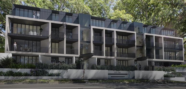
Multi-Residential
Bellevue Hill, NSW.
Company: Benson McCormack Architecture
Role: CC Packages - GAs, RCPs, Services Co-ordination, Stairs Drawings, Joinery Details, Adaptability Layouts, Fire Compartment Plans etc.
Information Displayed : Ground Floor Plan, Wall Section Details, Stair Section and plans.
05
Property of BMA
10 11 12 13 14 15 16 17 5 6 10 11 13 14 15 16 RWO FW FW FW FW FW FW FW FW FW FW FW FW FW FW DEEP SOIL 3 5 m PLANTER 4 9 m DEEP SOIL 4 3 m DEEP SOIL 8 4 m DEEP SOIL 10 4 m DEEP SOIL 7 9 m 10 12 13 10 11 12 13 14 15 16 17 WM PLANTER ON SLAB 5 8 m PLANTER ON SLAB 27 3 m DEEP SOIL WMC E + C WMC E + C AC AC T29 T1 T2 T3 T10 T12 T13 T14 T15 T11 GE CPE FG FG FG FG FG FG FG FG FG FG FG FG FG FG FG FG FG FG FG FG FG FG FG FG SPB SPB SPB SPB SPB SPB SPB SPB FG FG RWO BT IO IO ORG HT WM F OFFG OFFG OFFG OFFG OFFG OFFG OFFG OFFG OFFG OFFG WM WM WM HYD PG OFFG DEEP SOIL PLANTER ON SLAB 14 7 m 1 -505-010 2 A-505-010 16 PLANTER ON SLAB 3 9 m2 11 44,585 SSL 44,655 SSL 44,655 PD 42,480 FFL 44,125 FFL 44,125 FFL 44,125 FFL 44,125 FFL 44,125 FFL 44,125 FFL 44,125 FFL 44,125 FFL 44,125 FFL 44,125 FFL 44,125 FFL 44,125 FFL 44,125 FFL 44,125 FFL 44,125 FFL 44,125 FFL 42,440 PD 42,500 PD 42,420 PD 42,320 PD 42,160 FFL 44,125 05 A-310-002 05 A-310-002 01 A-310-001 02 -310-001 03 A-310-001 04 A-310-002 N -210-002 W A-210-002 E A-210-001 PLANTER ON SLAB 1 m DEEP SOIL PLANTER ON SLAB 1 7 m VD VD VD VD VD VD VD VD VD VD VD DP DP VD DP VD DP VD VD DPVD DP VD FE MIMIC FIP FE FE FHS FE PP LETTERBOXES RECESSED IN WALL PERIMETER DRAIN REFER CIVIL ENGINEER S DRAWINGS PERIMETER DRAIN REFER CIVIL ENGINEER S DRAWINGS GAS METER IN BLAST WALL ENCLOSURE STRIP DRAIN - REFER CIVIL ENGINEER S DRAWINGS STRIP DRAIN - REFER CIVIL ENGINEER S DRAWINGS FFN-03 ON SCREED AS REQUIRED TO ACHIEVE MIN 1 100 FALL - REFER TO PUBLIC DOMAIN DRAWINGS FFN-02 FFN-02 FFN-02 FFN-02 FFN-02 FFN-02 AD AD AD AD AD AD CHVP VP DP DP VD FFN-05 FFN-05 FFN-05 FFN-05 FFN-01 FFN-01 FFN-01 FFN-01 FFN-05 FFN-03 FFN-03 FFN-01 FFN-03 FFN-03 FFN-01 FFN-04 FFN-04 FFN-01 FFN-01 FFN-01 FFN-04 FFN-04 FFN-04 FFN-04 FFN-04 FFN-04 FFN-04 FFN-04 FFN-04 FFN-04 FFN-04 FFN-05 FFN-05 FFN-05 FFN-05 01 - C TOW 45 305 6 10 D72 13 6 12 6 12 10 D72A D71A 5 21CR 1 01 - C 5 00 - CR 5 00CR D24A D22A 00 - CR 1 10C W10 G12 W10 G12 G63M G63N 5 20CR G63W 011 01C 1 01 - C 1 01 - C 6 10 6 10 71A 6 10 6 10 D71 10 D72 34A 32A G63A 63A G63 G63 G63A 63S G63 G61A 1 10P 21 - CR 6 11 6 20 5 20 - CR 5 21CR 5 21CR 5 21CR 5 00CR 5 20CR 6 10 6 10 D71 6 10 6 20 6 13 6 10 6 10 6 11 6 10 6 10 D71 6 13 6 10 20 6 10 72A 6 10 11 6 10 6 12 6 12 10 6 12 5 00CR 5 00CR 5 00CR 5 00CR 5 00CR 5 00CR D70A 2170A 70A 1 10C 70A 20 - CR D70 D70 20 6 10 6 11 6 10 6 10 D71A 11 6 11 3 01 - CR 34B 32B 02 - CR 20 6 11 72A 6 10 6 10 6 10 6 10 6 10 71A 11 10 D72A 20 6 11 D72A 6 10 6 10 6 10 10 D71A 6 11 10 D72A 1 11 6 13 13 D71A D71 01 - P3 63 6 10 6 10 6 10 12 63H 6 12 G63B G63 6 12 G63E 12 63B G63H 12 G63P 63L FFN-03 FW FW FW FW VD FW VD FW VD FW VD FW VD FW VD FW FW FW OLD SOUTH HEAD ROAD TPZ TPZ TPZ TPZ TPZ TPZ TPZ TPZ TPZ TPZ TPZ TPZ TPZ TPZ TPZ TPZ TPZ TPZ TPZ TPZ TPZ TPZ PLANTER PLANTER B1 BT B2 BT2 GM B3 B1 SY B STAIR 1 STAIR 2 STAIR 3 STAIR 4 STAIR 6 STAIR 7 LIFT 1 LIFT 2 S SY B1 B2 BT S SY B B1 BT2 BT1 S S B2 B1 BT2 BT 50 2 m MSB 9 6 m2 METER 6 7 m2 47 5 m 21 8 m 21 0 m 8 2 m 14 8 m 15 0 m 5 1 m 8 0 m2 11 2 m 06 -510-060 08 -510-060 S -210-001 FW FHB 1 01 - C2 D72 4 01CR 4 01AR 1 2 3 4 6 7 8 9 A B C D E F G 1 5 WM 500 700 2b 7b FFL 42,340 DP FHS FFN-04 FFN-04 FFN-04 1 10 - C 3 12 1 12P 1 01C 2 1 01 - C 4 01CR 01 - CR 4 01 - AR1 3 12 1 10C 6 20 02 - CR 4 01a - CR 6 20 3 04 1 10C 3 21CR 3 21CR 3 04 1 01 - C 1 01 - C 3 10 3 10 6 12 4 00 4 01a - CR 4 00 SITE BOUNDARY EASEMENT K L D R R LY PY K L D R PY K L D R PY LY K L D R R PY LY K /D R R PY LY K /D PY LY R B 0 0 26 0 m2 A 0 0 25 9 m B 0 3 56 6 m A 0 1 71 7 m2 A 0 2 83 4 m B 0 2 84 3 m2 A 0 3 74 9 m B 0 1 49 5 m All drawings to AHD Australian Height Datum Read in conjunction with Structural Civil Hydraulic and Fire Engineers drawings and arborist report Slabs and columns shown are indicative refer to Structural Engineer drawings and architectural concrete profiles Notify BMA and Structural Engineer there are any discrepancies between these drawings All car parking areas to be min H2200mm to comply with AS2890 AS1428 1 All disabled car parking spaces to be min H2500mm to comply AS2890 6 + AS1428 All basement carparks to have 1 100 fall to drainage outlets to comply with Australian Standards ROOMS 1,2 Bedroom Bedroom etc BT1,2 Bathroom Bathroom etc GBR Garbage Room Kitchen Living Living Dining LI Linen LY Laundry PY Pantry Robe Storage SY Study WC Toilet HYDRAULIC SERVICES Basin BT Boundary Trap CO Clean Out FH Fire Hydrant FHB Fire Hydrant Boundary FHS Fire Hydrant Supply FE Fire Extinguisher FW Floor Waste HT Hose Tap HYD Attack Hydrant IO Inspection Opening OF Overflow ORG Overflow Relief Gully SD Sprinkler Dropper SK Sink EQUIPMENT Refridgerator Oven WM Washing Machine CIVIL STORMWATER DP Downpipe FG Floor Grate OFFG Overflow Floor Grate OF Overflow PG Planter Grate RWO Rainwater Outlet SPB Suspended Planter Box RWO VD Vertical Drop SERVICES AC Air Conditioning CPE Car Park Exhaust + Electrical Communications Cupboard FE Fire Extinguisher FH Fire Hydrant FHR Fire Hose Reel FHB Fire Hydrant Booster FHS Fire Hydrant Supply FIP Fire Indicator Panel GE Garbage Exhaust GM Gas Meters HYD Hydrant MIMIC MIMIC Panel PP Private Pillar electrical WMC Water Meters Cupboard GENERAL BP01 Bicycle Parking 01 TPZ Tree Protection Zone Tree 1 01- C WALL TYPE CODE FINISH TO BE READ IN CONJUCTION WITH FF& SCHEDULE 1 Ground 1:100 Chk Description Date PG PG PG PG for coordination for coordination - new structural scheme for information PRELIMINARY CC FOR CONSTRUCTION - CC 08 2022 08 2022 09 2022 29 09 2022 This drawing is issued upon the condition it is not copied reproduced retained or disclosed to any unauthorised person wholly or in part without prior consent in writing of benson mccormack architects Drawings show design intent only Shop drawings are to be provided for approval prior to construction or manufacture Do not scale drawings Check dimensions before commencing Inconsistencies are to be reported to benson mccormack ALL WORKS TO COMPLY WITH THE BUILDING CODE OF AUSTRALIA BCA 2019 + AUSTRALIAN STANDARDS AS **DIAL BEFORE YOU DIG** www 1100 com au NOTES AMENDMENTS PROJECT DETAILS 252-256 OSHR 252-256 Old South Head Road Bellevue Hill NSW 2023 DRAWING TITLE SCALE APPROVED NORTH CLIENT Shop - Liverpool 0296424632 www astuteproperty com au PCA Building Certificates Australia Robin Howard 225 Commonwealth Surry Hills NSW 2010 02 8014 7720 robin bcaustralia STRUCTURAL ENGINEER Suite 01 55 Miller Pyrmont NSW 2009 02 9516 0722 gian alarcon@eiaustralia com au MECHANICAL ENGINEER Aerow Engineering Michel Hedwan 41 Angus Crescent Yagoona NSW 2199 0414 166 650 hedwan LANDSCAPE ARCHITECT Higginson Landscape Pty Ltd Matthew Higginson po box 353 five dock nsw 2046 0414 725 944 mhla mhla com au FIRE ENGINEER Innova Services Jason Powell Suite 1805 Level 18 323 Castlereagh Street Sydney NSW 2000 1300 88 22 62 jason innovaservices BCA CONSULTANT Credwell Zoe Brown Suite 03 Level 233 Castlereagh St NSW 02 9281 8555 @credwell HYDRAULIC ENGINEER Bay Suite Ground Floor 68- Railway Burwood NSW 2134 1300 979 667 @goldfishbay com au ELECTRICAL ENGINEER Citiscope Hussein Abbas 0405 402 405 hussein@citiscope ACOUSTIC ENGINEER-CIVIL ENGINEER Civil Stormwater Engineering Osman Chowdhury Shop 143-147 Parramatta Road Concord NSW 2137 02 8397 6596 esgconsult LEGEND KEY PLAN GA Plans Ground Floor Plan Rev Date Description Revision ID Revision ID 17 29 09 2022 FOR CONSTRUCTION - CC 17 17 Project Address 252-256 Old South Head Road Bellevue Hill NSW 2023 Project Title 252-256 OSHR Regulated Design Record Drawing No A-110-008 Drawing Title Ground Floor Plan Lot & DP No.: Consent No DA 367 2017 4 Ground Floor Plan 20 Residential Apartments at Bellevue Hill. 06
Basement 40 920 PERIMETER DRAINREFER CIVIL ENGINEER S DETAILS CL 46 825 1 2 3 1 -510-100 2 -510-011 Level 01 47 225 1,040 BRICK ON SHEL ANGLE AXIOM LF3 T BASEPLATE AND HANDRAIL TO SUPPLIERS SPECIFICATIONS BALCONY TILES ON PEDESTALS FALL IN SLAB FALL IN SLAB 2 A-510-100 CAST IN BALCONY OUTLETS CL 49 925 4 -510-100 1 -510-100 3 -510-011 Level 02 50 325 1,030 AXIOM LF2 L BASEPLATE AND HANDRAIL TO SUPPLIERS SPECIFICATIONS BALCONY TILES ON PEDESTALS FALL IN SLAB FALL IN SLAB 3 A-510-100 CAST IN BALCONY OUTLETS CL 53 025 1 2 3 4 5 6 7 8 9 4 -510-011 4 -510-100 5 -510-011 Level 03 53 425 1,043 CONCRETE UPTURN CAST INTEGRAL TO SLAB - NO COLD JOINT - REFER STRUCTURAL ENGINEER S DETAILS AXIOM LF3 T BASEPLATE AND HANDRAIL TO SUPPLIERS SPECIFICATIONS BRICK ON SHEL ANGLE BALCONY TILES ON PEDESTALS PLANTER - REFER LANDSCAPE ARCHITECT S DETAILS FALL IN SLAB FALL IN SLAB CAST IN PLANTER OUTLETS CL 53 025 1 -510-100 Level 03 53 425 BALCONY TILES ON PEDESTALS INSULATION - REFER BASIX AND RCPs FALL IN SLAB CAST IN BALCONY OUTLETS CL 56 125 6 -510-011 Roof 56 525 METAL CAPPING 750mm DEEP HEKA HOOD AWNING METAL CLADDING INSULATION - REFER BASIX AND RCPs FALL IN SLAB 10 11 12 13 14 15 16 1 -510-100 1 -510-011 Ground 44 125 BALCONY TILES ON PEDESTALS CONCRETE UPTURN - REFER STRUCTURAL ENGINEER S DETAILS DAMP PROOF COURSE - RENDER OVER WATERPROOF MEMBRANE - WEEP HOLES @ 1200 C C FALL IN SLAB FALL IN SLAB FALL IN SLAB FALL IN SLAB BALCONY OUTLETS PLANTER OVERFLOWS AS PER AS4654 2 - OUTLETS REFER CIVIL ENGINEER S DRAWINGS CAVITY DRAIN OUTLETS 20 21 22 23 24 25 26 27 28 29 30 31 32 33 CAST CONCRETE CAPPING ON LOST FORMWORK SINGLE COURSE 190 BLOCK ON CAPPING BEAM CAPPING BEAM PILES & SHOTCRETE RETAINING TO STRUCTURAL ENGINEER S DETAIL B C 1 Wall Section 1 1:20 Chk Description Date Rev PG PG PG for coordination for information PRELIMINARY CC21 2022 2022 2022 03 05 06 This drawing is issued upon the condition it is not copied reproduced retained or disclosed to any unauthorised person either wholly or in part without prior consent in writing of benson mccormack architects Drawings show design intent only Shop drawings are to be provided for approval prior to construction or manufacture Do not scale drawings Check dimensions before commencing work Inconsistencies are to be reported to benson mccormack ALL WORKS TO COMPLY WITH THE BUILDING CODE OF AUSTRALIA BCA 2019 + AUSTRALIAN STANDARDS AS **DIAL BEFORE YOU DIG** www 1100 com au NOTES AMENDMENTS PROJECT DETAILS 252-256 OSHR 252-256 Old South Head Road Bellevue Hill NSW 2023 DRAWING TITLE Section Details Wall Sections 1 SCALE APPROVED STATUS DRAWN PROJECT No REV DRAWING No 1 20 PG CC 2155A 07 A-510-010 CLIENT Shop - Liverpool STRATHFIELD NSW 2136 0296424632 astuteproperty PCA Building Certificates Australia Robin Howard 225 Commonwealth St Surry Hills NSW 2010 02 8014 7720 STRUCTURAL ENGINEER EIAustralia Pyrmont 02 9516 0722 gian alarcon eiaustralia MECHANICAL ENGINEER Engineering Michel Hedwan 41 Angus Crescent Yagoona NSW 2199 0414 166 650 hedwan@aerow com au LANDSCAPE ARCHITECT Matthew Higginson Landscape Architecture Pty Ltd Matthew Higginson po mhla@mhla FIRE ENGINEER Suite 1805 Level 18 323 Castlereagh Street Sydney NSW 2000 1300 22 62 jason innovaservices BCA CONSULTANT Credwell Zoe Brown Suite Level 233 Castlereagh St Sydney NSW HYDRAULIC ENGINEER Goldfish Bay - Railway Burwood NSW 2134 1300 979 667 @goldfishbay ELECTRICAL ENGINEER Citiscope Hussein Abbas 0405 402 405 hussein citiscope ACOUSTIC ENGINEER-CIVIL ENGINEER Engineering Chowdhury Shop 143- Parramatta Road Concord NSW 2137 02 8397 6596 @esgconsult LEGEND KEY PLAN PG BENSON McCORMACK ARCHITECTURE 505 BALMAIN RD LILYFIELD NSW 2040 ABN 76 129 130 285 RN 7536 61 2 9818 0777 61 2 9818 0778 enquiries@bensonmccormack com W bensonmccormack Rev Date Description Revision ID Revision ID 07 29 09 2022 FOR CONSTRUCTION - CC 07 07 Project Address 252-256 Old South Head Road Bellevue Hill NSW 2023 Project Title 252-256 OSHR Regulated Design Record Drawing No A-510-010 Drawing Title Wall Sections 1 Lot & DP No.: Consent No DA 367 2017 4 Wall Sections 07
10 11 12 13 14 15 16 17 FG 250 300 TGSI DP VD DP VD MIMIC FHS 50MM NOSING STRIP W/ MIN LUMINANCE CONTRAST OF 30% IN ACCORDANCE W AS 1428 4,010 16 EQUAL GOINGS @ 250 50 50 1,000 50 50 15 50 300 FFL 44,125 A A B B CONTINUOUS HANDRAIL FIXED TO FULL HEIGHT BALUSTERS @ MAX 125 CTS 50MM NOSING STRIP W/ MIN LUMINANCE CONTRAST OF 30% IN ACCORDANCE W AS 1428 10 11 12 13 14 15 16 17 FG FG 250 300 TGSI VD DP DP VD FHS FG FH 50MM NOSING STRIP W/ MIN LUMINANCE CONTRAST OF 30% IN ACCORDANCE W AS 1428 A A B B 4,010 16 EQUAL GOINGS @ 250 300 50 1,000 50 50 300 FFL 47,225 TGSI 10 11 12 13 14 15 16 17 FG 250 300 TGSI VD DP DP VD FHS FH 50MM NOSING STRIP W MIN LUMINANCE CONTRAST OF 30% IN ACCORDANCE W AS 1428 A A B B 300 4,010 16 EQUAL GOINGS @ 250 300 50 50 1,000 50 50 FFL 50,325 TGSI 10 11 12 13 14 15 16 17 FG FG FFL 53,425 DP DP FHS FH A A B B 300 4,010 16 EQUAL GOINGS @ 250 50 50 1,000 50 50 TGSI 50MM NOSING STRIP W MIN LUMINANCE CONTRAST OF 30% IN ACCORDANCE W AS 1428 D E F Ground 44 125 Level 01 47 225 Level 02 50 325 Level 03 53 425 Roof 56 525 3,100 17 EQUAL RISERS @ 182 3,100 17 EQUAL RISERS @ 182 3,100 17 EQUAL RISERS @ 182 900 900 900 FFL 44,125 FFL 47,225 FFL 50,325 FFL 53,425 NOSING STRIP W/ MIN LUMINANCE CONTRAST OF 30% IN ACCORDANCE W/ AS 1428 F E D 900 900 900 3,100 17 EQUAL RISERS @ 182 3,100 17 EQUAL RISERS @ 182 3,100 17 EQUAL RISERS @ 182 FFL 53,425 FFL 50,325 FFL 47,225 FFL 44,125 NOSING STRIP W MIN LUMINANCE CONTRAST OF 30% IN ACCORDANCE W/ AS 1428 1 Stair 1 - Ground 1:50 2 Stair 1 - Level 01 1:50 3 Stair 1 - Level 02 1:50 4 Stair 1 - Level 03 1:50 5 Stair 1 Section AA 1:50 6 Stair 1 Section BB 1:50 NOTE: ALL LANDINGS AND TREAD FINISHES TO ACHIEVE MINIMUM SLIP RESISTANCE OF P3 DRY)/P4 WET) IN ACCORDANCE W/ AS 1428 ALL LANDINGS AND TREAD ACHIEVE MINIMUM SLIP RESISTANCE DRY)/P4 WET IN ACCORDANCE Chk Description PG PG PRELIMINARY CC FOR REVIEW FOR CONSTRUCTION - CC NOTES AMENDMENTS PROJECT DETAILS 252-256 OSHR 252-256 Old South Head Road 2023 DRAWING TITLE SCALE APPROVED STATUS DRAWN PROJECT No DRAWING No 1 50 PG CC 2155A A-441CLIENT Shop - Liverpool astuteproperty PCA Building Certificates Australia Robin Howard 225 Commonwealth St Surry Hills NSW 2010 02 8014 7720 robin@bcaustralia com au STRUCTURAL ENGINEER EIAustralia Gian Alarcon Suite 01 55 Miller St Pyrmont NSW 2009 02 9516 0722 gian alarcon eiaustralia MECHANICAL ENGINEER Aerow Engineering Michel Hedwan 41 Angus Crescent Yagoona NSW 2199 0414 166 650 hedwan@ LANDSCAPE ARCHITECT Matthew Higginson Landscape Architecture Pty Higginson po @ FIRE ENGINEER Innova Services Jason Powell Suite 1805 Level 18 323 Castlereagh Street Sydney NSW 2000 1300 88 62 jason@innovaservices com au-LEGEND Stairs & Ramps Stair 1 PG 5 505 BALMAIN RD LILYFIELD NSW 2040 ABN 76 129 130 285 RN 7536 P +61 2 9818 0777 F +61 2 9818 0778 E enquiries@bensonmccormack com W www bensonmccormack com Rev Date Description Revision ID Revision ID 03 29 09 2022 FOR CONSTRUCTION - CC 03 03 Stairs Details 08
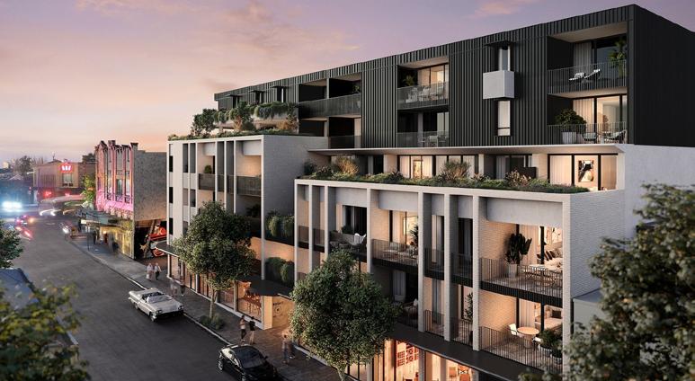
Mixed Use
Marrickville, NSW.
Company: Benson McCormack Architecture
Role: CC Packages - GAs, RCPs, Services Co-ordination, Stairs Drawings, Joinery Details, Adaptability Layouts, Fire Compartment Plans, Wall Sections etc.
Information Displayed : Ground Floor Plan, Level 1 Plan, Elevations, Wall Section Details.
09
1 : 4 1 : 8 1 8 1 1 1 REFER C V ENG NEER S DRAW NGS FOR PUBL C DOMA N & VEH CLE RAMP DETA L 1 8 RWO RWO S 1C S 1 a S B E L E C 6 0 0 6 0 0 MRV C EAR NCE H GHT 4 TURN NG RAD US 0 0 S R V C L E A R A N C E H E G H T 3 5 T U R N N G R A D U S 7 1 G X PR C S T E E C C O M M H Y M E E R 1550 1550 1550 1000 1550 1550 1000 1550 1550 GAS ME ER FH FH FSHB HYD METER FW FW FW FW S X FW FW BTFW BTFW B FW P F H R F H R F H R H R F H R S 1D 1 A-60 -00 17 18 18 RL 13 250 RL 13 250 RL 13 250 RL 14 000 RL 14 000 FFL 14 020 SSL 14 000 F F L 1 4 0 1 0 F F L 1 4 1 6 0 SSL 1 ,2 0 S S L 1 3 1 5 0 PD 12 670 PD 2 850 PD 13 050 PD 13 260 PD 1 ,4 0 BB 310-002 CC 310-003 CC 310-003 DD 310-004 01 A-531-010 08 A-531-080 09 A-531-090 07 A-531-070 03 A-531-030 04 A-531-040 120 #Lay D 10 A-531-100 11 A-531-110 L1 A-603-001 L2 A-603-001 BULKY WASTE 5 7 m S 0E S 0 G1 A S6 G 1 A S 0 6 K 6 6 L D 0 D 0 D 8 D 0B NTER-TENANCY WALLS BETWEEN COMMERC AL TENANC ES TO BE PART OF F T OUT - FUTURE OCAT ON SHOWN DASHED NTER-TENANCY WALLS BETWEEN COMMERC AL TENANC ES TO BE PART OF F T OUT - FU URE LOCAT ON SHOWN DASHED MAKE PROV S ON FOR FUTURE ACCESS B E WC - ROUGH N AND CAP ALL REQU RED SERV CES MAKE PROV S ON FOR FUTURE ACCESS BLE WC - ROUGH N AND CAP ALL REQU RED SERV CES GRATED DRA N - REFER C V L AND STRUCTURAL ENG NEERS DRAW NGS GRATED DRA N - REFER C V L AND STRUCTURAL ENG NEERS DRAW NGS GRATED DRA NS - REFER C V AND STRUCTURAL ENG NEERS DRAW NGS GRATED DRA NS - REFER C V L AND STRUCTURAL ENG NEERS DRAW NGS AD GSL VP AD 5 A M N 3sqm MECH OUVRE - REFER MECHAN CA ENG NEER S DRAW NGS FOR DETA LS REFER LANDSCAPE ARCH ECT S DETA LS TOW+14 010 T O W + 1 4 1 6 0 TOW+14 800 D 0A 3 B 3 A 5 B D 0A D9 B D9 C D 0D 3 A D 4 3 C D 2 D 2 D3 B D3 B D 1C D3 C D 3A 6 C S 0H S 0 S 0 S 0 S 0D S6 A 0 2 A D2 A 3 P OSD ACCESS HATCHES - REFER C V L ENG NEER S DETA L STEEL PLATFORM FOR OSD ACCESS AND BA USTRADES TO PREVENT FALLS DP AD DP CV CV D4 B F RE / SMOKE CURTAINS TO L FT LAND NG DOORS - REFER F RE ENG NEER S REPORT FOR DETA LS ANY SERV CE PENETRAT ONS W TH N THE COVERED AREA OF THE PEDESTR AN EN RANCE AND LOBBY SHALL BE F RE AND SMOKE SEPARATED N ACCORDANCE W TH BCA CLAUSE C3 15 AND SPEC F CAT ON C3 15M - REFER F RE ENG NEER S REPORT FOR DETA L 5 2 1 5 2 1 5 1 1 2 1 1 02 1 0 1 5 1 5 21 2 1 0 5 2 1 3 1 5 3 1 5 3 1 5 3 15 5 1 5 2 314 1 0 1 3 1 5 21 5 2 5 2 1 1 0 1 314 5 2 1 5 2 2 5 1 3 0 0 5 2 1 5 1 1 0 4 1 0 1 5 3 00 3 0 5 2 1 1 0 3 1 0 1 1 0 3 1 2 0 5 2 1 5 2 1 0 1 0 2 1 0 1 1 0 2 1 0 1 1 0 1 0 1 0 1 3 1 5 3 1 5 1 2b 1 02b 3 1 5 5 2 1 5 0 3 1 10 1 5 2 2 03 5 1 5 0 00 L L A W A R R A R O A D M A R R I C K V I L L E L A N E EX S NG TREE TO BE RETA NED M A I L B O X E S A C UN TS N SCREENED ENCLOSURE WASTE COLLECT ON VEH CLE L NE OF ROOF OVER ROLLER DOOR ROLLER DOOR ROLLER DOOR L NE OF 6 m SETBACK EX ST NG TREE TO BE RETA NED L NE OF RETA L AWN NG OVER L NE OF RETA L AWN NG OVER L I NE OF RETA I L AWN I NG OVER COMMS ROOM FS3 FS4 SECURE PARCEL DROP MA N SW TCH ROOM PLATFORM FOR OSD ACCESS V A R I E S M A X 1 : 1 0 4 1 : 3 6 V E H C L E R A M P 1 L FT 1 FS1 L FT 2 FS2 1 1 4 V A R I E S M A X 1 : 2 0 L I NE OF 2 m COUNC I L LAND DED I CAT I ON FDC E FFCP V A R E S V A R I E S V A R E S 1 :40 FFN-05 RET 01 A: 118 1 m2 RET 03 A: 100 4 m2 RET 04 A: 112 7 m2 RET 02 A 79 2 m2 OSD 12 3 m 49 2 m LOAD NG DOCK (EXCL LIFT/FS/PLANT) 268 6 m2 671 6 m CH 3,750 mm RESI WASTE 55 1 m2 COMM WASTE 21 4 m RES LOBBY 55 9 m AA 310-001 NE210002 SE 210-003 S W 2 1 00 0 4 NW 210-001 1 01 02 A-531-020 D PEDESTR AN BARR ER TO VEH CLE DR VEWAY - STEE P PE RA L @ M N m ABOVE F N SHED GROUND LEVEL - CLEAR V S ON ABOVE AND BE OW D 0C STA R 5 REFER C V L ENG NEER S DRAW NGS FOR PUBL C DOMA N & LOAD NG DOCK APRON A B C D E F G H J K L 01 01 03 03 04 04 05 05 06 06 M 02 02 01a 01a 05b 05b 05a 05a 05c 05c 07 07 01b 01b 02b 02b 1 d w g HD A s 2 R d n c n u c o w h a d F En e d w n 3 S a s a d c mn h wn d w g n h u c E g n e e a n 4 A a g a a o AS 2 5 A a d c a g p AS 9 + AS 2 6 A a m a a c mp w h A s a a a d O MS 1 d m e m T 2 a h m h o B a b o e n D n D n g n u Y n o a Y d W e Y R U R E a n T o a p O n O H H n H H n B d H H n S p E E n W W T o T Y k H n n c n O n n F e fl w R e fl w R e u D p k p K Q ME T e a o e WM W g M ch n O MWAT R P o n G F G e fl w F o G F e fl w G e WO w u P s n n e D D E V C C C P k x s + + C mm E E n H H d a H H e R H H n B H H d a p d c n E a b h s M a M e s Y d M M C M M a P c WM W Me e C b E E A P g 1 Z n 1 GROUND 1:100 Ch De p o D D D D R h s d w n s u d u o e e r d s s d o n p w o o c n D w n h w d g n o a p v p o aw g C e k d m n o s n a L WO KS T COM US RA BC 0 A w NO ES AMENDME TS PR J C D T S MOSA C 265-273 l awar a R DR W NG L C EN S W PCA H @ S RUCTUR L ENG NEE @ M CH N C L ENG N ER & M H d @ m L NDS AP A CH ECT M M @ F E NG N ER P L GEN KE L N Rev Date Desc ipt on DP Fu l Name Reg No 18 24 3 2 23 FOR CC DAV D BENSON DEP0000579 Pro ec Add ess 265-273 awa ra Road Ma r ckv e NSW 2204 Pro ec T e MOSAIC Regu a ed Design Reco d Body Co pora e Reg No #Body Co p Consent No: 201700349 Draw ng No A-110-008 D aw ng T e Ground F oo P an Ground Floor Plan 10
13 18 15 19 F F F VD F F F F RWO GAX TX ELEC COMMS HYD METER DX CPX KX KX FG FG FG FG FG FG FG FG PG PG FG FG FG FG FG FG FG FG FG REF 350 350 FG GB SHUTE 975 800 HYD 1550 F HYD F FH FH FW FW FW FW FW FW FW FW FW FW FG FG FG FG FG FG FG PG PG PG FG GB SHUTE 975 800 1 A-510-001 12 13 BB 310-002 CC 310-003 CC 310-003 DD 310-004 01 A-531-010 08 A-531-080 09 A-531-090 07 A-531-070 03 A-531-030 04 A-531-040 120 #LayID 10 A-531-100 11 A-531-110 F 450 515 FFL 17,510 FFL 17,510 FFL 17,510 FFN 17,510 FFL 17,510 FFL 17,510 FFN 17,510 FFL 17,510 FFL 17,510 FFN 17,510 FFN 17,510 FFN 17,510 FFL 17,510 FFL 17,510 FFL 17,510 FFN 17,510 FFL 17,510 FFL 17,510 FFL 17,510 FFN 17,510 FFL 17,510 FFN 17,510 FFL 17,510 FFL 17,510 AA 310-001 NE 210002 SE 210-003 SW 210004 NW 210-001 W66 G63Da G63Da G63D G63D G63D G63 G63La G63R G63 G63W G63B 63Ua G63U 63T 63E 63Q G63Q G63E G63R 63E G63 G63 W66 W66A W66A W66A D70A 70A D70A D70A D70A D70 D70A D70 70A D70 D50 50C D71A 71A D72B D72 D72 D71 D72 D71A D72A D71A 71A D72B D72A D72B D71 D71A D72C D71A D72C D71A 71A 72C 71B D71 D72 D72C D73 D72 D71 71A D73B 72C D32D D34B D31G D31D D31 D31 D34B D32D G63H W69A W69C VD VD VD VD VD VD VD VD VD VD VD VD VD VD VD VD VD VD VD DP DP ST ST DP ST VP DP ST TWV VD ST DP ST VD ST AD DP CV CV TMV ST VD ST RV DP W66Dc W69H BUILTIN PLANTERSREFER LANDSCAPE ARCHITECT S DRAWINGS GRC PLANTERS -REFER LANDSCAPE ARCHITECT S DRAWINGS 1 01 5 10 1 01 1 04 TOW 18 600 3 21 3 11 3 11 b 5 10 20 3 21 b 1 01 3 11 b 3 11 b 3 13 3 11 b 21 1 01 1 01 5 10 5 10 4 07 4 00 6 20 6 20 4 01 5 10 5 00 5 10 10 5 10 5 10 3 20 3 20 3 20 3 12 3 11 3 11 b 510 1 20 1 21 1 11 1 10 5 00 3 20 3 01 3 00 3 04 1 10 3 01 3 00 3 04 6 10 6 10 6 10 6 10 6 10 6 10 6 10 6 10 6 10 10 6 10 6 10 6 10 6 20 20 6 10 6 10 6 10 6 10 6 10 6 10 6 20 6 10 6 10 6 10 6 10 10 6 10 20 6 20 6 10 6 10 6 10 6 10 6 10 6 10 6 10 6 10 6 10 6 10 6 10 6 10 6 10 6 10 6 10 6 10 10 10 6 10 6 20 1 10 1 01 1 01 3 01 10 1 10 3 00 1 10 3 01 1 01 3 02 00 3 00 3 02 5 00 5 02 5 00 5 00 5 00 5 00 5 00 5 00 5 00 5 11 5 00 5 00 5 00 5 00 5 00 5 00 5 00 5 11 5 00 5 11 5 00 5 00 5 02 6 13 6 13 6 13 6 13 13 10 6 13 6 13 02 4 00 a 4 00 4 00 a 4 00 a 5 00 6 20 20 12 3 20 3 20 4 01 01 4 01 01 01 01 4 01 4 01 01 01 4 01 01 4 07 4 01 4 01 3 13 6 10 10 11 10 6 10 6 10 6 10 13 10 6 11 6 10 6 10 6 10 6 10 6 10 6 13 6 10 6 11 6 10 6 10 6 10 6 10 6 10 6 13 1 01 3 13 5 10 3 20 6 10 6 10 6 10 6 10 6 10 6 10 10 6 10 6 10 6 20 6 10 6 10 6 10 6 10 6 10 6 10 3 11 b 5 10 5 10 5 10 5 10 1 11 1 11 1 11 5 00 6 20 6 20 I L L A W A R R A L A N E M A R R I C K V I L L E L A N E LINE OF 6m SETBACK LINE OF 2 m COUNCIL LAND DEDICATION OPERABLE SCREEN FIXED SCREEN L L A W A R R A R O A D FFN-01 FFN-02 FFN-02 FFN-03 FFN-04 FFN-04 FFN-04 FFN-01 FFN-03 FFN-02 FFN-01 FFN-02 FFN-03 FFN- 4 FFN-04 FFN-01 FFN-02 FFN-02 FFN-03 FFN-01 FFN-03 FFN-04 FFN-04 FFN-02 FFN-01 FFN-04 FFN-03 FFN-02 FFN-02 FFN-03 FFN-03 FFN-04 FFN-04 FFN-01 FFN-02 FFN-0 FFN-04 FFN-04 FFN-01 FFN-02 FFN-02 FFN-03 FFN-03 FFN-04 FFN-02 FFN-02 FFN-03 FFN-03 FFN-04 FFN-01 FFN-01 FFN-03 FFN-02 FFN-05 FFN-05 LIFT 1 LIFT 2 FS1 FS2 FFN-03 OPERABLE SCREEN AWNING - REFER STRUCTURAL AND CIVIL ENGINEER S DRAWINGS AWNING - REFER STRUCTURAL AND CIVIL ENGINEER S DRAWINGS AWNING - REFER STRUCTURAL AND CIVIL ENGINEER S DRAWINGS AWNINGREFER STRUCTURAL AND CIVIL ENGINEER S DRAWINGS BA ENS B1 MB BA Bar ENS MB B1 SY Li LY BA Bar ENS MB B1 SY Li LY BA Bar ENS MB B1 SY Li LY P 02 A-531-020 A B C D E F G H J K L 01 01 03 03 04 04 05 05 06 06 M 02 02 01a 01a 05b 05b 05a 05a 05c 05c 07 07 01b 01b 02b 02b WX HYD HYD HYD HYD HYD HYD HYD FW FW FW FW FW FW FW FW FW FW FW FW FW FW FW FW FW FW FW FW FW FW FW FW FW FW FW FW FW FW HYD HYD HYD 6 20 6 10 20 1 10 1 10 10 6 10 6 10 6 10 6 10 6 20 L D K L D K L D K B1 L D BA K P LY S B1 L D BA K P LY S B1 L D BA K P LY S B1 L S D BA Y K B1 L S D BA LY K B1 L D MB K ENS L D K BA POS 25 m2 POS 26 2 m 101 2BR + St A 88 8 m2 102 1BR + St A 53 1 m 104 2BR + St A 88 m2 106 2BR + St A 88 8 m 110 1BR + St A 50 1 m 107 1BR + St A 53 1 m POS 25 m POS 25 m POS 14 8 m2 103 1BR + St A 53 1 m 105 1BR + St A 56 1 m 108 2BR + St A 75 0 m 109 2BR A 75 1 m2 POS 11 m POS 11 4 m POS 11 4 m POS 13 8 m POS 13 m POS 13 m POS 10 m POS 10 m POS 1 m 1 All drawings to AHD Australian 2 Read in conjunction with Structural and Fire Engineers drawings 3 Slabs and columns shown drawings and architectural concrete Engineer if there are any discrepancies 4 All car parking areas to be AS1428 5 All disabled car parking spaces AS2890 + AS1428 6 All basement carparks to have comply with Australian Standards ROOMS 1,2 Bedroom Bedroom BT1,2 Bathroom Bathroom GBR Garbage Room Kitchen Living D Living Dining LI Linen LY Laundry PY Pantry Robe Storage SY Study WC Toilet HYDRAULIC SERVICES Basin BT Boundary Trap CO Clean Out FH Fire Hydrant FHB Fire Hydrant Boundary FHS Fire Hydrant Supply FE Fire Extinguisher FW Floor Waste HT Hose Tap HYD Attack Hydrant IO Inspection Opening OF Overflow ORG Overflow Relief Gul SD Sprinkler Dropper SK Sink EQUIPMENT Refridgerator Oven WM Washing Machine CIVIL STORMWATER DP Downpipe FG Floor Grate OFFG Overflow Flo Grate OF Overflow PG Planter Grate RWO Rainwater Outlet SPB Suspended Planter VD Vertical Drop SERVICES AC Air Conditioning CPE Car Park Exhaust + Electrical + Communications FE Fire Extinguisher FH Fire Hydrant FHR Fire Hose Reel FHB Fire Hydrant Booster FHS Fire Hydrant Supply FIP Fire Indicator Panel GE Garbage Exhaust GM Gas Meters HYD Hydrant MIMIC MIMIC Panel PP Private Pillar electrical WMC Water Meters Cupboard GENERAL BP01 Bicycle Parking 01 TPZ Tree Protection Zone Tree 1 LEVEL 01 1:100 Chk Description PG DB DB DB DB DB DB for coordination for information FOR INFORMATION for structural coordination for information FOR BASIX COORDINATION for information for information FOR CC This drawing is issued upon retained or disclosed to any part without prior consent Drawings show design intent for approval prior to construction drawings Check dimensions Inconsistencies are to ALL WORKS TO COMPLY WITH BCA 2019 + AUSTRALIAN DIAL www NOTES AMENDMENTS PROJECT DETAILS MOSAIC 265-273 Illawarra Road DRAWING TITLE CLIENT Property Shop astuteproperty PCA Building Certificates Australia Pty Ltd Robin Howard 02 8014 7720 admin@bcaustralia net au STRUCTURAL ENGINEER EI Australia Graeme Deaker 02 9516 0722 service@eiaustralia MECHANICAL ENGINEER Goldfish & Bay Michel Hedwan 1300 979 667 Michel Hedwan@goldfishbay LANDSCAPE ARCHITECT MHLA Matthew Higginson 0414 725 944 mhla@mhla com au FIRE ENGINEER Innova Jason Powell 0409 887 929 jason innovaservices com au LEGEND KEY PLAN Rev Date Description DP Full Name Reg No 13 24 03 2023 FOR CC DAVID BENSON DEP0000579 Project Address 265-273 Illawarra Road Marrickville NSW 2204 Project Title MOSAIC Regulated Design Record Body Corporate Reg No: #Body Corp Consent No: 201700349 Drawing No A-110-010 Drawing Title: Level 1 Plan Level 1 Plan 11
L K J H G F E D C B A STL1 BASEMENT 02 +7 300 BASEMENT 01 +10 300 GROUND +14 100 LEVEL 01 +17 500 LEVEL 02 +20 600 LEVEL 03 +23 700 LEVEL 04 +26 800 LEVEL 05 +29 900 ROOF +33 000 3,000 3,800 3,400 3,100 3,100 3,100 3,100 3,100 1,030 1,020 1,020 1,030 1,020 TOW 30,525 TOW 33,300 34,200 TOS TOW 33,300 TOW 24,740 TOW 27,840 450 450 1,050 60G S11 S60 G61 11A W66G W66 W66 W66E W66 S60K 63Ua G63U G63U G63 G63U G63 G63U G63 G63Q G63Q G63E G63 G63Q G63Q G63E G63R G63E G63R G63 G63R G63E G63U G63 G63M G63N G63N G63U G63U G63U 63Uc G63Uc 63Uc G63 W69G 63Sa W69F G61 W60A W60A W60A S60 S60D S60A 60B S60 11Ca 11C S60Ea 60C D25 26A W66A W66A W66A 63H 63H 63H 61B 11A CONC 2 BAL 1 BAL 1 BAL A BAL 1 BAL A BAL A BAL B BAL 1B BAL 1B BAL A BAL A BAL B BAL A BAL 2 BAL A BAL 2 BAL A BAL 2 BAL B BAL B BAL A BAL 2 BAL 2 BAL 2B BAL A BAL 2 BAL 2 BAL 2 BAL 1 BAL 2 BAL A BAL B BAL 2 BAL 2 BAL A BAL B BAL 1 BAL 2 BLK 1 BWK2 BWK2 RSCR CONC1 APPROXIMATE 20 0m HEIGHT REFERENCE AT FRONT BUILDING LINE APPROXIMATE 20 0m HEIGHT REFERENCE AT BUILDING LINE L4-L5 GAS METER RESIDENTIAL ENTRY FHB MARRICKVILLE LANE BWK2 MCL1 BWK2 CONC1 BWK1 CONC1 REFER TO FF&E SCHEDULE FIXTURES AND FINISHES 1 All drawings to AHD Australian Height 2 Read in conjunction with Geotechnical Hydraulic Engineers information 3 Slabs and columns shown are indicative drawings and architectural concrete profiles 4 All car parking areas to be min 2200mm AS1428 All disabled parking spaces with AS2890 6 + AS1428 1 5 Refer to BCA BASIX mechanical access 6 Refer to concrete outline plans & reflected and ceiling interfaces 7 Refer to architectural drawings to ascertain thickness and materials 8 Window sills & rebated panels fall to outside 9 Sub-sills and sub-heads not shown for 10 Refer to external materials and finishes 11 Colour to all aluminium capping to match 1 Refer to manufacturers details and speci cladding and paint finishes WHERE NOMINATED ON DRAWINGS ORSCHEDULES MULTIPLE TYPES BAL BALUSTRADE TYPE SCHEDULES FOR FURTHER INFORMATION AC Air Conditioning ACC Accessible ADP Adaptable AHD Australian Height Datum AL Aluminium AWN Awning B1,2 Bedroom Bedroom etc BAL Balustrade BG Box Gutter BLK Blockwork BL Bollard BT Bathroom BK Brickwork BALC Balcony CAP Capping CLD Cladding CJ Construction Joint CL Ceiling Level COF Off form Concrete COL Column CONC Concrete COMS Communications Services COS Communal Open Space CPE Car Park Exhaust CPC Concrete Precast CPD Cupboard CWB Car Wash Bay CWM Cold Water Meter CWS Cold Water Supply D Dining DB Distribution Board DP Down Pipe ELEC Electrical Services EX Existing EXH Exhaust Fire Services FB Facebrick FCC Fire Control Centre FCR Fire Control Room FEX Fire Extinguisher FNC 1,2 etc Fence FFL Finished Floor Level FH Fire Hydrant FHR Fire Hose Reel FIP Fire Indicator Panel FMP Fire Mimic Panel FRL Fire Resistance Level FS 01,02 Fire Stair No 1 etc FW Floor Waste GBC Garbage Chute GBR Garbage Room GDR Grated Drain GEX Garbage Exhaust GPT Gross Pollutant Trap GR Grab Rail H Hydraulic Services HR Handrail HWM Hot Water Meter HWS Hot Water Service HWU Hot Water Unit IL Invert Level INS Insulation J 01,02 K KB KEX L 01,02 L L D LY LV M MBP MBX MVJ MV MSB MTR NGL NOM OFS OSD OSR P PCF PF R R REF REQS RWH RWO S SC SDO SFL SIM SKL SO SP STL ST 01 STY SWD SWP TCE TGSI TOW TYP UNO U UT V VS VP WC WIR North West Elevation 1:100 Chk Description PG DB DB DB DB DB for coordination for information for information FOR BASIX COORDINATION for NCC review FOR CC Inconsistencies are to be reported Architecture ALL WORKS TO COMPLY WITH THE BUILDING BCA 2019 + AUSTRALIAN STANDARDS DIAL BEFORE YOU www 1100 com NOTES AMENDMENTS PROJECT DETAILS MOSAIC 265-273 Illawarra Road Marrickville DRAWING TITLE SCALE APPROVED STATUS DRAWN PROJECT No DRAWING No 1 100 DB CC 2123A A-120-001 CLIENT ASTUTE Property Shop Strathfield South NSW 2136 astuteproperty PCA Building Certificates Australia Pty Ltd Robin Howard 02 8014 7720 admin@bcaustralia net au STRUCTURAL ENGINEER EI Australia Graeme Deaker 02 9516 0722 service eiaustralia com au MECHANICAL ENGINEER Goldfish Bay Michel Hedwan 1300 979 667 Michel Hedwan@goldfishbay com au LANDSCAPE ARCHITECT MHLA Matthew Higginson 0414 725 944 mhla@mhla com au FIRE ENGINEER Jason Powell 0409 887 929 jason@innovaservices com au BCA Credwell Chris 02 9281 chris HYDRAULIC Goldfish Fadi Taouk 1300 @gold ELECTRICAL Citiscope Hussein 0405 hussein ACOUSTIC Acoustic Moussa 02 9793 info CIVIL Osman 02 8397 osmanc LEGEND KEY PLAN GENERAL ARRANGEMENT North West Elevation PG SS ND ARCHITECTURE STUDIO 5 505 BALMAIN RD LILYFIELD NSW 2040 ABN 76 129 130 285 NOMINATED ARCHITECTS David Benson ARBNSW 7285 Glenn McCormack ARBNSW 7536 61 9818 0777 61 9818 0778 enquiries@bensonmccormack com W www bensonmccormack com Rev Date Description DP Full Name Reg No 06 24 03 2023 FOR CC DAVID BENSON DEP0000579 Body Corporate Reg No #Body Corp Consent No 201700349 Drawing No A-120-001 Drawing Title North West Elevation Elevation 12
GROUND +14 100 1 -532-001 4 -531-041 LEVEL 01 +17 500 BOX GUTTER - REFER CIVIL ENGINEER S DETAIL KLIPLOK STEEL ROOF SHEET @ DEG PITCH SOFFIT LINING STEEL TO STRUCTURAL ENG DWG ROLLED SINGLE CLADDING PANEL AS AWNING EDGE PROFILE TO MANUFACTURER S SPEC BAL 2B MIN 1 100 MAX 1 20 FALLS IN STRUCTURAL SLAB MONOLITHIC HOB OVERFLOW 1 -532-001 2 -532-001 3 -531-041 LEVEL 02 +20 600 1,010 WATERPROOFING TO GO OVER THE BALUSTRADE FIXINGS BALUSTRADE FORMS DRIP EDGE CLEAR PENETRATIVE SEALER TO FACADE ENGINEERS SPEC MIN 1 100 MAX 1 20 FALLS IN STRUCTURAL SLAB BAL 1A STORM MOULD AND SEALANT AS IDENTIFIED IN THE FACADE REPORT 1 -531-041 1 -532-001 2 -532-001 LEVEL 03 +23 700 1,030 65 FOLDED METAL ROOF CAPPING ON BLOCKING AS REQUIRED - FALLS TO INSIDE OF BUILDING PRESSURE SEAL AT REAR - POWDERCOAT TO MATCH WALL CLADDING DRAINAGE CELL WRAPPED IN GEOTEXTILE MEMBRANE WATERPROOF MEMBRANE TO TANK INSIDE OF PLANTER DULUX AcraTex AcraSheild MIN 100 OVER WATERPROOF MEMBRANEFILL LEVEL MIN 100BELOW MEMBRANE TERMINATION OVERFLOW PIPE DULUX AcraTex AcraSheild SKIM COAT WATERPROOF MEMBRANE UPTURN POURED MONOLITHICALLY OR WATERSTOP USED HERE WEEPHOLE FLASHING AND SHELF ANGLE UV STABLE WATERPROOFING COLOUR GREY CLEAR PENETRATIVE SEALER TO FACADE ENGINEERS SPEC MIN 100 MAX 1 20 FALLS IN STRUCTURAL SLAB MIN 100 FALLS IN STRUCTURAL SLAB MONOLITHIC UPTURN FACE BRICK WATERPROOF MEMBRANE TO TURN UP UPSTAND BY MIN 100mm CAST IN DRAINAGE WATERPROOF MEMBRANE TO TERMINATE INSIDE THE SLEEVE OF PUDDLE FLANGE AS PER AS4654 2 DRIP GROOVE WEEP HOLE AND DPC WATER RESISTANT CONCRETE SEALER OVERFLOW STORM MOULD AND SEALANT AS IDENTIFIED IN THE FACADE REPORT 1 -532-001 2 A-531-041 LEVEL 04 +26 800 1,020 DULUX AcraTex AcraSheild SKIM COAT TO EXPOSED CONCRETE MIN 100 MAX 1 20 FALLS IN STRUCTURAL SLAB MIN 1 100 FALLS IN STRUCTURAL SLAB DRIP GROOVE UV STABLE WATERPROOFING TO TERMINATE AT ANGLE ENSURE COLOUR IS GREY OVERFLOW BAL 1B STORM MOULD AND SEALANT AS IDENTIFIED IN THE FACADE REPORT 5 SIM -531-011 2 A-532-001 FOLDED METAL ROOF CAPPING ON BLOCKING AS REQUIRED - FALLS TO INSIDE OF BUILDING PRESSURE SEAL AT REAR - POWDERCOAT TO MATCH WALL CLADDING SARKING OVER SLAB EDGE PROPRIETARY TOE CAP OR PERFORATED VERMIN MESH UV STABLE TRAFFICABLE WATERPROOF MEMBRANE TURN UP AND OVER UPTURN CLEAR PENETRATIVE SEALER TO FACADE ENGINEERS SPEC COVER EXPOSED SOFFIT TO DRIP LINE MONOLITHIC UPTURN OVERFLOW SNAPLINE 45 CLADDING ON PROPRIETARY FIXING SYSTEM - INSTALL TO MANUFACTURER S DETAILS STORM MOULD AND SEALANT AS IDENTIFIED IN THE FACADE REPORT 01 02 01a 01b 02b LEVEL 05 +29 900 1 A-110-008 Wall Section 04 Scale 1 20 Chk Description DB DB DB DB for information for facade eng review for information FOR CC This drawing is issued upon the condition not retained or disclosed to any unauthorised person part without prior consent in writing of Benson Architecture Drawings show design intent only Shop drawings for approval prior to construction or manufacture drawings Check dimensions before commencing Inconsistencies are to be reported to Benson Architecture ALL WORKS TO COMPLY WITH THE BUILDING CODE BCA 2019 + AUSTRALIAN STANDARDS **DIAL BEFORE YOU DIG** 1100 NOTES AMENDMENTS PROJECT DETAILS MOSAIC 265-273 Illawarra Road Marrickville DRAWING TITLE SCALE APPROVED STATUS DRAWN PROJECT No DRAWING No 1 20 DB CC 2123A A-531-040 CLIENT ASTUTE Property Shop Strathfield South NSW 2136 02 9642 4632 astuteproperty PCA Building Certificates Australia Pty Ltd Robin Howard 02 8014 7720 STRUCTURAL ENGINEER Graeme Deaker service@eiaustralia MECHANICAL ENGINEER Goldfish Bay 1300 979 667 goldfishbay LANDSCAPE ARCHITECT Matthew Higginson 0414 725 944 mhla mhla FIRE ENGINEER Innova Jason Powell jason innovaservices BCA CONSULTANT Credwell Chris Campbell 02 9281 8555 HYDRAULIC Bay Fadi Taouk ft goldfishbay ELECTRICAL Citiscope 0405 402 405 citiscope ACOUSTIC Moussa Zaioor 02 9793 1393 info@acousticsolutions CIVIL + STORMWATER Civil Stormwater Osman Chowdhury esgconsult LEGEND KEY PLAN CONSTRUCTION DETAILING Wall Section 04 JE PG McCORMACK ARCHITECTURE STUDIO 505 BALMAIN RD LILYFIELD NSW 2040 ABN 76 129 130 285 NOMINATED ARCHITECTS David Benson ARBNSW 7285 Glenn McCormack ARBNSW 7536 61 9818 0777 +61 9818 0778 enquiries@bensonmccormack com W www bensonmccormack com Rev Date Description DP Full Name Reg No 06 24 03 2023 FOR CC DAVID BENSON DEP0000579 Project Address 265-273 Illawarra Road Marrickville NSW 2204 Project Title MOSAIC Regulated Design Record Body Corporate Reg No #Body Corp Consent No 201700349 Drawing No A-531-040 Drawing Title Wall Section 04 Wall Section Details 13
PAGE HAS BEEN INTENTIONALLY LEFT BLANK
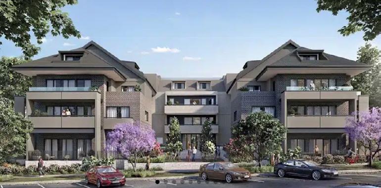
Multi-Residential
Class 2 at Camden, NSW.
Company: Benson McCormack Architecture
Role: Construction Documentation - GAs, Elevations, Sections, Concrete Profiles, Wall Type Details, Wall Setouts, Wall Section Details, Wall Type Details, Enlarged Plans, Schedules, Fire Compartment Drawings
Information Displayed : Ground Floor Plan, Wall Setout Plans, Enlarged Plan, Sectional Details.
14
Property of BMA
GSPublisherVersion 1863.0.0.22 STW STW STW W 03 W 54 W 52 54 PLATFORM LIFT 333 ° 00 ' 15 " BOUNDARY 13 19 6 DW DW H STACK ELEC 700 300 700 300 FW RWO RWO RWO RWO RWO RWO RWO RWO RWO RWO RWO RWO RWO RWO DW FW RWO RWO RWO FW RWO RWO DW RWO PDO RWO PDO PDO PDO PDO PDO PDO RWO PDO PDO RWO PDO RWO RWO RWO RWO RWO RWO STACK GER PER PFX PFX PFX PFX PFX FIP HT PO HT HT HT WP PO HT HT HT W W 1550 1550 VI VI VI OF FH FH PDO PDO PDO PDO RWO RWO RWO PDO OF F DW F DW F F FW FW FW OF OF OF OF OF OF OF OF OF OF OF OF OF OF OF OF OF PDO PDO PDO PDO OF PDO PDO PDO PDO OF RWO PDO PDO OF OF RWO RWO OF RWO OF OF OF OF OF OF OF OF OF OF OF OF OF OF OF 100 RWO A-0800 -0800 SCRN3 A-0800 -43 A-0755 -44 -0755 -45 A-0755 D-47 -0755 -0952 D-48 A-0830 -50 -0830 D-59 A-0756 -60 A-0756 -61 -0756 -44 -0755 E1 A-0201 S1 A-0200 W1 A-0201 W A-0202 S A-0202 150 5,895 150 1,800 1,200 1,000 1,200 1,600 1,000 1,199 1,100 1,760 FFL 72.00 FFL 72.00 FFL 72.75 FFL 72.75 72.50 FFL 72.75 FFL 71.99 FFL 72.74 FFL 71.99 FFL 72.75 FFL 71.99 FFL 71.99 FFL 72.74 FFL 71.70 FFL 73.00 FFL 72.64 TOW 71.70 TOW 71.70 71.25 FFL 72.51 FFL 72.73 FFL 72.60 FFL 73.00 FFL 72.81 FFL 73.00 FFL 73.00 72.45 FFL 72.67 45.00° 45.00° 45.00° C A-0301 E -0302 E A-0302 B1 -0801 B1 -0801 F -0302 F A-0302 D26 A-0802 D27 A-0802 B13 -0800 B13 A-0800 A14 A-0800 A14 A-0800 Cond# - columns reduced by 50% Cond 1 0 2 d - columns reduced by 50% Cond# 2 d - columns reduced by 50% Cond# - columns reduced by 50% Cond# - stairs and screen Cond# - stairs and screen FRL-/90 90 FRL120 120 120 FRL -/ 90 90 FRL -/ 90 / 90 CONVEX MIRROR ON POLE STOP SIGN GIVE WAY TO PEDESTRIANS FRL -/ 90 90 FRL120 120 120 FRL120 120 120 FRL 120 120 120 FRL120 120 120 FRL 120 120 120 FRL 90 90 -/ 90 90 FRL-/90 90 -/ 90 90 FRL -/ 90 / 90 FRL 90 90 FRL120 120 120 FRL120 120 120 FRL120 120 120 FRL120 120 120 Cond# - Flood free Stair link to John Street FF013 FF013 FF013 FF013 FF013 FF013 FF013 FF013 FF013 FRL 90 90 FRL -/ 90 / 90 LINEAL GRATE FF120 FF120 FF120 FF120 FF120 FF120 FF120 FF120 FF120 FF120 FF120 FF120 FF120 FF120 FF120 FF120 FF120 FF120 FF120 FF120 FF120 FF011 FF121 FF010 FF000 TOW + 71 89 TOW + 72 58 TOW 73 35 TOW +73 35 TOW + 73 35 TOW + 73 35 TOW + 73 35 TOW + 73 35 TOW 72 75 TOW +71 89 TOW + 71 89 FF005 FF011 FF011 FF005 TOW +71 89 FF005 FF005 R R ST ST OV R R ST ST OV ST 1 R ST OV P ST 1 R ST OV P FF013 FF013 HOB 50 TOW +73 70 Cond# - Flood free path from build 1 link to John Street 4 21 WF 05 4 21 WF05 05 4 20 WF 05 02 WF13 WF 13 1 02 WF13 02 WF13 21 WF05 1 02 C WF 05 C 02 WF05 1 02 C WF 05 02 WF05 02 WF05 20 WF05 20 WF05 1 02 WF13 02 WF13 02 FW178 J O H N S T R E E T B U I L D I N G 4 & 6 PLAZA 71 30 71 38 71 65 ] 71 82 ] 71 11 71 03 70 80 70 70 ] 70 55 ] FS3 LIFT LIFT NBN COMMS 70 85 71 52 ] 71 65 71 96 70 48 70 33 71 19 71 39 [ 71 49 ] 1 20 MSSB AHD 7 2 50 0 1 : 8 1 5 1 : 14 1 : 40 ENTRY LOBBY FS1 FS4 FS 70 90 71 50 HIGH LEVEL WINDOW HIGH LEVEL WINDOW 1 : 20 RESIDENT LOUNGE SOP AHD 72 250 BENCH SIGNAGE STORAGE UNDER BENCH STORAGE UNDER BENCH WATER METERS GAS BOOSTER PLANTING PLANTING PLANTING PLANTING PLANTING REF LANDSCAPE 20 RAMP EL200 OR SIMILAR % FALL 1 40 FALL % FALL 1 8 PL50 REF LANDSCAPE ARCH DOCS PL50 REF LANDSCAPE ARCH DOCS PL50 REF LANDSCAPE ARCH DOCS COUNTER BENCH PL50 PL50 APPROVED SUBDIVISION PLAN FALL REFER TO CIVIL ENG DOCUMENTATION FOR PUBLIC DOMAIN SH-PIT 72 09 SH-PIT SH-PIT 72 25 SH-PIT 72 24 KERB RAMP TO AS 1428 1 KERB RAMP TO AS 1428 1 1 8 BED 1 A 13 5 m FF130 BED 2 A 11 7 m FF130 BED A 15 m FF130 FF140 38 4 m FF140 A 44 m BED 2 10 5 m FF130 BED 3 10 4 m FF130 BED 2 11 5 m FF130 BED 1 A 15 1 m FF130 BED A 17 0 m2 FF130 BED 2 A 12 0 m FF130 BED A 12 m2 FF130 FF140 A 33 1 m FF140 A 16 4 m FF140 A 29 9 m BED 2 10 8 m FF130 BED 3 11 1 m FF130 BED 1 A 17 2 m FF130 BED 1 A 15 m FF130 BED 2 A 11 m FF130 BED 2 10 6 m FF130 BED A 10 m FF130 BED 1 14 3 m FF130 FF140 A 33 m FF140 A 44 2 m FF140 A 16 5 m FF140 A 30 3 m2 A A-0300 A A-0300 D A-0753 D A-0754 F A-0721 F A-0721 F -0722 5 04 WF01 2,000 FX-03 FX-03 FX-03 FX-03 D22A D 40 A BENCH PL50 REF LANDSCAPE ARCH DOCS POS 22 7 m POS 22 4 m POS 24 0 m POS 22 7 m POS 22 6 m POS 16 9 POS 21 9 POS 16 6 POS 21 8 H STACK STACK STACK 4,022 3 02 WF 110 04 WF02 6 02 WF110 SCRN3 D 40 A N1 A-0200 G63 A A 2 2 3 3 1 1 5 5 6 6 4 4 7 7 C C D D E E G G STACK STACK H STACK H STACK STACK STACK H H HYD 800 250 HYD 800 250 H STACK H STACK B B F F CEX 900 850 CEX 950 400 H STACK H STACK STACK STACK STACK H STACK STACK WC VI H STACK STACK FW FW FW FW STW STW OF OF OF OF OF OF OF -0803 1,800 12,000 1,855 3,010 3,010 3,060 10,445 1,900 8,720 8,820 1,815 10,430 2,115 2,986 2,115 3,000 3,000 3,035 3,366 3,575 3,003 3,000 3,015 3,241 4,705 3,657 3,260 3,140 3,000 3,020 3,140 3,865 3,422 4,700 5,088 3,288 3,091 3,113 3,997 5,088 3,020 3,140 3,000 3,140 3,260 3,008 4,785 3,241 4,705 3,369 3,575 5,545 3,133 3,000 3,015 3,000 3,536 14,915 7,765 1,900 13,040 11,800 3,000 10,445 1,900 8,720 8,820 1,815 10,430 120 2,987 4,841 3,012 3,478 5,930 8,985 7,765 1,900 6,520 6,520 11,800 9,000 3,000 2,500 2,600 720 1,060 2,100 720 900 1,200 1,200 1,200 1,200 1,200 900 1,700 1,700 130 1,300 130 1,412 1,340 310 1,400 5,545 45,250 1,000 FFL 72.75 SILL HEIGHT +74.54 B -0300 B -0300 ST AC AC AC AC AC AC AC 02 WF110 3 02 WF 110 02 WF110 3 02 WF 110 3 02 WF 110 5 06 WF02 02 WF110 20 WF01 16 WF110 INDUCTION LOOP ST P R R R 3 04 WF 112 5 06R WF11 06 WF01 06 WF01 06 WF11 5 06 WF 02 5 06 WF02 5 06 WF 02 5 06 WF02a 5 06 WF 01 5 06 WF 01 5 06 WF01 5 06 WF 01 5 00 WF 01 06 WF01 06 WF11 06 WF01 08R WF10 1 08 14 WF110 02 WF110 1 10 WF 01 08 WF11 1 08 Conc 5 06 WF 01 3 02 WF 110 06 WF01 06 WF11 5 06 WF01 5 06R WF11 5 06 WF01 00 WF01 5 06 WF 01 5 06 WF 01 A 5 06 WF01 06 WF01 5 06 WF 01 1 10 WF 02 02 WF110 3 04 WF 112 FRL -/ 90 / 90 04 WF112 3 02 WF 110 5 06 WF 101 5 06 WF02a 5 06 WF 02 6 06 WF 10 14 WF11 02 WF01 6 04 WF 10 1 06 WF110 1 16 WF 110 16 WF110 5 06 R WF 110 5 04 WF02 1 16 WF 110 TOW + 74 00 TOW +74 00 TOW 73 80 TOW +74 00 TOW +73 75 TOW + 73 75 TOW + 73 75 TOW +73 60 TOW +73 75 TOW +73 75 TOW + 73 75 TOW + 73 65 TOW 73 80 TOW +73 65 TOW +73 65 TOW 73 65 TOW + 74 00 TOW 74 00 TOW + 74 00 TOW +73 65 TOW +74 00 TOW + 73 65 TOW 73 65 TOW 73 65 TOW +73 65 TOW 73 65 TOW 73 75 AC ST P R 1 OV OV EF 2 EF 2 EF 2 EF EF EF DP DP DP DP DP DP DP DP DP DP DP DP DP DP DP DP DP DP DP OF DP OF DP DP DP DP DP DP DP DP DP DP DP DP DP DP DP DP DP DP DP DP DP DP DP DP OF DP DP DP DP DP 06 WF01 06 WF02 6 06 WF 10 1 21 WF02 06 WF02 5 06 WF02 06 WF11 21 WF02s WF 100 WF100 WF100 WF 100 WF 100 WF110 TOW 71 05 TOW + 71 05 TOW + 71 94 TOH + 71 94 TOW 71 99 TOW +71 99 TOW +73 80 TOW 73 80 TOW + 73 70 TOW +73 50 TOW +73 50 TOW + 73 50 TOW 73 50 TOW +73 50 TOW +73 50 02 WF110 3 01 3 00 00 3 01 TOW + 73 74 TOW + 73 80 TOW +73 70 TOW 73 70 TOW + 73 70 TOW +75 45 DP DP DP DP OF DP DP DP DP OF DP DP OF OF OF DP DP DP DP DP DP DP TGSI FX03 TGSI TGSI TGSI 21 WF05 FURTHER INVESTIGATION WITH FER WF 110 6 02 WF 110 WF 110 6 10 WF 100 DP TOW +73 81 TOW 73 81 TOW +73 81 TOW +73 80 TOW +73 65 TOW 73 80 SCRN3 EF EF 4 20 WF 05 4 21 WF 05 20 WF05 4 20 WF 05 21 WF05 4 21 WF 05 4 21 WF 05 4 21 WF 05 1 08 WF13 08R WF13 1 08 WF 13 1 08R WF13 1 08 R WF 13 WF13 08 WF13 08 WF13 08R WF13 WF13 WF13 1 08 R WF 13 FX-11 FX-11 FX-11 FX-11 4 20 WF05 W69Z SILL + 08 D 70 A 63 G G G 61 61 11 11 W 60 B W 60 B W 60 B D 70 A W66 D 72 A 66 W66 63 W66 W66G G63Y G 67 C G 63 C W66 W66E W67 W67A W67 W67 D 70 63 34 D71A D 71 A 72 73 D73B G11C D71 D71B D 71 A D72A 73 71 D71B D 71 A D72A 34 73 73 G11C D30B 32 D33B 32 33 33 33 33 D 71 A 71 72 72 71 72 D72A D71 71 72 73 D71A 71 D 71 A D72 73 G 13 A G63 G 63 P D 70 A W66C G63F G 63 P G 63 F G 63 V 08 WF10 W66C G63F D 70 A BENCH BENCH ACCESS HATCH N E P E A N S T R E E T PL50 PL50 PL50 PL50 PL 50 REF LAN D SCAPE ARCH DOCS PL50 REF LANDSCAPE ARCH DOCS BUILDING 3 INTERNAL SUBDIVISION 8 3007 A 92 1 m2 2 BEDROOM 3001 A 105 m 3 BEDROOM 3002 A 84 3 m 2 BEDROOM 3005 A 84 6 m 2 BEDROOM 3006 A 105 3 m2 3 BEDROOM 3004 AREA 113 0 m 3 BEDROOM 3003 A 114 6 m 3 BEDROOM D A-0301 D A-0301 LEGEND AC Air Conditioning ACC Accessible ACS Access Control System ADP Adaptable AHD Australian Height Datum AL Aluminium ASPH Asphalt AWN Awning B1,2 Basement etc BAL Balustrade BD1,2 Bedroom Bedroom 2 etc BG Box Gutter BC Barge Capping BKP Bicycle Parking BKR Bicycle Rack BLK Blockwork BL Bollard BT Bathroom BY Balcony CAP Capping CD Cladding CJ Construction Joint CL Centre Line CLNR Cleaner Store CONC Concrete COF Concrete Off-Form Finish COL Column COMS Communications Services COS Check on Site CEX Car Park Exhaust CPC Concrete Precast CPD Cupboard CPL Cover Plate CPT Carpet CR Cement Render CTF Ceramic Tile Floor Finish CTYD Courtyard CWB Car Wash Bay CWM Cold Water Meter CWS Cold Water Supply D Dining DB Distribution Board DP Down Pipe DRY Dryer DW Dishwasher ELEC Electrical Services EF External Furniture EG Eaves Gutter EXH Exhaust FB Facebrick FC Fibre Cement FCC Fire Control Centre FCR Fire Control Room PFX Portable Fire Exting FFL Finished Floor Level FF### Floor Finish ### FH Fire Hydrant FHB Fire Hydrant Booster FHR Fire Hose Reel FIP Fire Indicator Panel FMP Fire Mimic Panel FRL Fire Resistance Level FS Fire Stair No FW Floor Waste FX-## Fixture Type ## GA 01 Gate GB Gas Bayonet GBC Garbage Chute GDR Grated Drain GEX Garbage Exhaust GR Grab Rail H Hydraulic Services HP High Point HR Handrail HWM Hot Water Meter HWS Hot Water Service HWU Hot Water Unit IL Invert Level INS Insulation 01,02 Joinery Type 01 02 etc K Kitchen KB Kerb KEX Kitchen Exhaust 01,02 Lift No etc Living LP Low Point LRA Lobby Relief Air LSA Lobby Supply Air LY Laundry LV Louvre MBP Motor Bike Parking MBX Mail Box MDR Metal Deck Roofing MECH Mechanical Services MT Metal MVJ Movement Joint MOV Microwave Oven MV Mechanical Vent MSB Main Switch Board MTR Meter NGL Natural Ground Level NOM Nominal Operable OF Over Flow Spout OSD On Site Detention Tank OSR On Site Retention Tank OV Oven P Pantry PCF Powder Coat Finish PNF Paint Finish PV Paving R Robe Recessed RA Return Air RRC Roof Ridge Capping RF Refrigerator RN Render RO Roller Door RWH Rain Water Head RWO Rainwater Outlet S Storage SA Sandstone SC Screen SCOL Steel Column SDO Spoon Drain Outlet SFF Stone Floor Finish SFL Structural Floor Level SIM Similar SKL Skylight SO Structural Opening SOP Set Out Point SP Stair Pressurisation SS Stainless Steel STL Steel STN Stone STY Study STW Stormwater Drain SWP Stormwater Pit Thermal TB Timber TCE Terrace TD Timber Deck TGSI Tactile Ground Surface Indicator TL Tiles TFF Timber Floor Finish TOW Top of Wall TYP Typical UNO Unless Noted Otherwise U Underside UT Utility Space Void VL Vinyl VS Visitor VP Vent Pipe WB Weatherboards WC Toilet WF## Wall Finish ## WIR Walk in Robe WM Washing Machine All drawings to AHD Australian Height Datum). Read in conjunction with Geotechnical Structural and Hydraulic Engineers information Slabs and columns shown are indicative refer to Structural Engineer drawings and architectural concrete profiles Notify BMA and Structural Engineer there are any discrepancies between these drawings All car parking areas to be min 2200mm to comply with AS2890 AS1428 All disabled car parking spaces to be min H2500mm to comply with AS2890 + AS1428 SEPP SENIORS LIVING - ENSURE PATHWAY LIGHTING PROVIDES AT LEAST 20LUX AT GROUND FLOOR - ENSURE LIGHTING DOES NOT CAUSE GLARE FOR PEDESTRIANS AND ADJACENT DWELLINGS - LETTERBOX S ARE LOCATED WITHIN A COMPLIANT LOCATION IN EXISTING BUILDING 1 PATH OF TRAVEL TO THE MAIL ROOM IS ACCESSIBLE P 61 9818 0777 F + 61 9818 0778 STUDIO 505 BALMAIN RD LILYFIELD NSW 2040 ABN 76 129 130 285 NOMINATED ARCHITECTS David Benson ARBNSW 7285 Glenn McCormack ARBNSW 7536 2203A DRAWING No CHECKED SCALE APPROVED STATUS PROJECT No DRAWING TITLE REV NORTH PROJECT DETAILS This drawing is issued upon the condition it is not copied reproduced retained disclosed to any unauthorised person either wholly in part without prior consent in writing of benson mccormack architects Drawings show design intent only Shop drawings are to be provided for approval prior to construction or manufacture Do not scale drawings Check dimensions before commencing work Inconsistencies are to be reported to benson mccormack **BEFORE YOU DIG AUSTRALIA** byda ALL WORKS TO COMPLY WITH THE BUILDING CODE OF AUSTRALIA BCA 201 AUSTRALIAN STANDARDS AS BUILDING 3 1 100 CC3 IFC A-0101 JE DB BCA CONSULTANT STRUCTURAL ENGINEER FIRE ENGINEER CIVIL & FLOOD ENGINEER FACADE ENGINEER KEY PLAN CLIENT - HTB CUSTOM DEVELOPMENT CERTIFICATIONS Angel Sydney 61 8279 6088 customcert -LAB CONSULTING Carrington Sydney 0447 343 458 -lab Suite 14 02 Level 14 49 York st Sydney NSW 2000 61 9058 7517 adamseng 32 Lolanthe St Campbelltown NSW 560 02 4625 5055 beveridgewilliams Sydney NSW 2060 02 9922 5200 E enquiries@bensonmccormack com www bensonmccack com W MECH ELEC & HYD ENGINEER VERTICAL TRANSPORT ENGINEERLevel 121 Walker North Sydney NSW 2060 bse BUILDING SERVICES ENGINEERS - BSE Sydney 02 9922 5200 LANDSCAPE ARCHITECT ESD-SECTION BASIX MATHEW HIGGINSON LANDSCAPE ARCH -MHLA Sydney 0414 725 944 mhla com au Energy Science House 11 157-161 Gloucester The Rocks NSW 2000 certifiedenergy AMENDMENTS 61 0407 750 712 htbuilding 2-14 John Street Camden NSW 2570 BENSON McCORMACK ARCHITECTURE GEOTECHNICAL ENGINEER DOUGLAS AND PARTNERS Grange 4647 0075 douglaspartners TRAFFIC ENGINEER VARGA TRAFFIC Young Bay 9904 3224 vargatraf PCA Jack Guo - MCKENZIE GROUP Level 189 Kent Sydney mckenzieACOUSTIC ENGINEER Level 32 85 Casltlereagh St Sydney NSW 2000 61 8279 6088 viggroup WASTE ELEPHANTS FOOT 112 116 Canterbury Rd Bankstown NSW 200 elephants STORMWATER HARRIS PAGE ASSOCIATES Level Carrington Street NSW 20 harrispageassociates GENERAL ARRANGEMENT - GROUND PLAN DRAWINGS ARE ONLY TO BE READ AT THE SCALE IN WHICH THEY ARE PRODUCED DO NOT ZOOM IN OR ENHANCE DRAWINGS TO OBTAIN FURTHER DETAIL CONTACT THE ARCHITECT DRAWINGS MUST BE VIEWED & PRINTED IN COLOUR Chk Description Date Rev JE JE JE JE JE JE Preliminary FOR COODINATION Preliminary Preliminary CC FOR REVIEW PRELIMINARY CC FOR FINAL COMMENT COORDINATION PRELIMINARY FACADE PACKAGE ISSUED FOR CONSTRUCTION - CC 2022 2022 2022 2023 2023 07 2023 06 08 10 12 14 16 16 Rev Date Description DP full Name Reg No 16 07 2023 ISSUED FOR CONSTRUCTION - CC3 David Benson DEP0000579 Project Address 2-14 John Street Camden NSW 2570 Project Title BUILDING 3 Regulated Design Record Drawing No A-0101 Drawing Title GENERAL ARRANGEMENT - GROUND PLAN Lot & DP No.: Lot 2 DP 1211137 Consent No DA-693 2019 Ground Floor Plan 15
All drawings to AHD Australian Height Datum Read in conjunction with Geotechnical Structural and Hydraulic Engineers information Slabs and columns shown indicative refer to Structural Engineer drawings and architectural concrete profiles Notify BMA and Structral Engineer there are any discrepancies between these drawings All car parking areas to be min 2200mm to comply with AS2890 AS1428 All disabled parking spaces to be min H2500 to comply with AS2890 AS1428 All basement carparks to have 200 fall drainage outlets comply with Australian Standards Floor and fixture reference tag Refer to Finish Fixture and Equipement schedule FRAMED DIMENSION DENOTES SETOUT TO DOOR OPENING LEGEND Align AC Air Conditioning ACC Accessible ACS Access Control System ADP Adaptable AHD Australian Height Datum AL Aluminium AWN Awning 1,2 Bedroom Bedroom 2 etc BAL Balustrade BG Box Gutter BKP Bicycle Parking BKR Bicycle Rack BLK Blockwork BL Bollard BT Bathroom BWK Brickwork BY Balcony CAP Capping CBF Concrete Broom Finish CEA Concrete Exposed Aggr Finish CFF Concrete Float Finish CTFF Ceramic Tile Floor Finish CGF Concrete Groove Finish CHS Circular Hollow Section Cast In CJ Construction Joint CL Centre Line CLNR Cleaner Store CONC Concrete COF Concrete Off-Form Finish COL Column COMS Communications Services COS Check on Site CPE Car Park Exhaust CPC Concrete Precast CPD Cupboard CPL Cover Plate CPT Carpet CSF Cementitious Screed Finish CST Concrete Steel Trowel Finish CWB Car Wash Bay CWM Cold Water Meter CWS Cold Water Supply Dining DB Distribution Board DP Down Pipe DRY Dryer DW Dishwasher Entry ELEC Electrical Services EX Existing EXH Exhaust Fire Services FCC Fire Control Centre FCR Fire Control Room FEX Fire Extinguisher FFL Finished Floor Level FH Fire Hydrant FHR Fire Hose Reel FIP Fire Indicator Panel FLS Flashing FMP Fire Mimic Panel FN 01,02 Furniture Type 01 02 etc FEP 01,02 Fire Egress Passage etc FRL Fire Resistance Level FS 01,02 Fire Stair No etc FW Floor Waste GB Gas Bayonet GBC Garbage Chute GBR Garbage Room GDR Grated Drain GEX Garbage Exhaust GHR Garbage Holding Room GPT Gross Pollutant Trap GR Grab Rail GVL Gravel DT Hydrant HD Hand Dryer Electric HP High Point HMR High Moisture Resistance HR Handrail HWM Hot Water Meter HWS Hot Water Service HWU Hot Water Unit IL Invert Level INS Insulation IO Inspection Opening 01,02 Joinery Type 01 02 etc K Kitchen KB Kerb KEX Kitchen Exhaust 01,02 Lift No etc Living LP Low Point LRA Lobby Relief Air LSA Lobby Supply Air LT Laundry Tub LDY Laundry LV Louvre M Mechanical Services MBP Motor Bike Parking MBX Mail Box Assembly MDR Metal Deck Roofing MVJ Movement Joint MOV Microwave Oven MV Mechanical Vent MSB Main Switch Board Service incl Main Distribution Board & Frame MTR Meter NGL Natural Ground Level NOM Nominal Operable OFS Over Flow Spout OSD On Site Detention Tank OSR On Site Retention Tank OV Oven P Pantry PCF Powder Coat Finish PD Pivot Door PF Paint Finish PFC Parallel Flange Channel PV Paving R Robe Recessed RA Return Air RD Roller Door REF Refrigerant Pipe Riser RF Refrigerator RHS Rectangular Hollow Section RL Relative Level to AHD RWH Rain Water Head RWO Rainwater Outlet RV Reflux Valve S Sewer SCN Screen SCOL Steel Column SD Sliding Door SDO Spoon Drain Outlet SFF Stone Floor Finish SHS Square Hollow Section SIM Similar SK Sarking SKL Skylight SKT Skirting SO Structural Opening SOP Set Out Point SPK Sprinklers SS Stainless Steel STL Steel ST 01 Stair No etc STY Study SWD Stormwater Drain SWP Stormwater Pit Thermal TCE Terrace TD Timber Deck TGSI Tactile Ground Surface Indicator TND Tundish TFF Timber Floor Finish TOW Top Wall TYP Typical UNO Unless Noted Otherwise U S Underside UT Utility Space V Void VS Visitor VP Vent Pipe WC WC Accessible Female M Male unisex WIR Walk in Robe WM Washing Machine WPM Waterproof Membrane STW STW STW 2 03 W 54 W 52 54 13 19 5 H STACK ELEC 700 300 FW RWO RWO RWO RWO RWO RWO RWO RWO RWO RWO RWO RWO RWO FW RWO RWO RWO FW RWO RWO ELEC PDO RWO PDO PDO PDO PDO PDO RWO PDO PDO RWO PDO RWO RWO RWO RWO RWO STACK GER PER PFX PFX PFX PFX PFX FIP VI VI OF FH FH PDO PDO PDO PDO RWO PDO DGPO DGPO DGPO DGPO DGPO OF FW FW OF OF OF OF OF OF OF OF OF OF OF OF OF OF PDO PDO PDO PDO OF PDO PDO PDO PDO RWO PDO PDO OF OF RWO RWO OF OF RWO RWO OF OF OF OF OF OF OF OF OF OF OF OF OF OF OF 100 RWO 123 1,300 2,100 90 460 1,000 2,100 191 1,000 2,100 474 415 1,104 109 723 1,573 774 515 1,485 190 363 900 1,000 2,100 115 450 865 3,102 705 1,280 840 1,300 205 75 1,401 840 1,300 810 75 34 2,296 160 1,880 HEBEL 160 35 15 255 3,030 75 1,310 75 1,645 75 1,645 75 1,331 75 3,155 850 538 395 1,000 2,100 140 3,140 673 75 930 199 840 1,300 255 1,798 505 297 1,039 708 1,450 98 4,320 700 4,043 255 2,143 893 255 70 75 1,635 1,000 2,100 95 255 693 2,537 1,000 2,100 60 2,400 3,145 1,000 2,100 1,675 3,023 1,006 424 98 1,200 2,100 255 66 1,000 2,100 1,077 922 125 35 215 840 2,400 194 2,041 255 75 50 1,000 2,100 493 1,777 125 35 30 525 3,480 2,400 765 3,460 1,857 1,458 1,580 2,730 925 341 555 3,055 244 1,635 1,000 2,100 95 541 75 575 630 2,330 244 2,371 840 2,400 710 630 125 2,420 1,658 2,400 3,015 590 255 1,545 3,480 2,400 650 5,670 1,800 2,400 894 1,550 255 182 255 3,343 545 380 90 1,300 2,100 90 190 3,103 1,000 2,100 37 1,000 2,100 160 340 1,610 730 710 55 2,760 600 165 908 753 800 333 329 1,381 695 1,635 550 2,465 160 2,880 2,400 240 1,350 4,064 1,915 430 1,545 909 1,856 2,200 116 100 130 4,370 3,150 2,660 200 120 63 1,000 2,100 27 230 1,915 15 255 585 160 405 1,000 2,580 1,000 1,000 2,580 1,000 670 330 45 1,465 30 1,135 995 270 1,915 160 3,110 400 1,847 988 1,420 101 1,000 2,100 138 530 212 487 490 328 122 160 80 893 2,603 75 250 1,675 75 300 75 31 1,350 2,100 30 33 42 75 3,160 1,000 2,100 165 615 2,600 840 58 75 988 840 909 75 1,000 2,100 554 1,121 75 954 1,000 2,100 1,613 225 33 42 158 75 1,940 1,000 1,500 770 611 41 73 841 159 1,652 2,337 75 2,750 1,000 2,100 75 1,494 160 1,880 HEBEL 160 35 15 1,465 30 15 1,700 2,400 170 75 180 840 1,300 274 1,795 508 297 2,330 1,310 75 587 1,000 2,100 191 1,000 2,100 587 75 1,331 152 1,000 2,100 538 850 673 3,155 615 315 75 673 3,155 1,525 1,000 2,100 1,072 60 1,000 2,100 2,522 708 255 123 1,300 2,100 90 2,143 515 1,675 363 865 3,102 2,215 868 230 4,118 868 3,480 2,400 840 2,400 15 1,635 1,000 2,100 80 556 650 75 555 18 3,480 2,400 747 108 840 2,400 121 75 2,041 255 125 1,000 2,100 493 1,777 125 35 850 341 555 1,580 1,000 2,100 1,802 3,285 1,637 2,842 1,000 2,100 937 75 542 3,145 255 2,145 695 3,023 665 160 325 1,675 98 1,200 2,100 255 66 1,000 2,100 1,077 1,048 3,022 844 947 10 3,480 2,400 390 260 275 100 50 75 255 725 1,533 75 195 635 915 1,800 2,400 3,480 2,400 145 1,106 2,145 55 12 1,000 2,100 803 730 242 2,880 2,400 474 415 1,104 832 1,573 787 230 10,445 1,900 8,720 8,820 1,815 10,430 5,930 8,985 7,765 1,900 6,520 6,520 255 3,030 75 3,051 950 3,490 650 226 CRANE PENO 6 01 - P 6 01 - P 6 01P 6 01P 016 01P 6 02P 6 02P 6 01P 016 06WF 10 6 01P 6 01P 6 02P 6 01P 6 01P 6 01 - P 6 01P01016 01 - P 6 026 01P 6 01P 6 01P 0101 - P 016 01P016 01P 02 - P6 02P 6 02P 01 - P 6 02P6 02 - FB 6 01 - P 01 - P 6 01P 6 01P 01 - P 6 01P 6 01P 6 01 - P 016 02 - P 6 01P 016 02P 6 02P 01 - P 6 02P 6 01 - P 01 - P 6 01P 6 01P 6 01P 6 01 - P6 01P 6 01 - P 01 - P WF 100 HOB 50 FW178 J O H N S T R E E T B U I L D I N G 4 & 6 PLAZA LIFT LIFT NBN COMMS 1 20 MSSB ENTRY LOBBY FS4 FS2 RESIDENT LOUNGE SOP AHD 72 250 FILL IN ONCE CRANE REMOVED 3003 3002 3001 3004 3005 3006 3007 5 04 WF01 FX-03 FX-03 D22A D 40 H STACK STACK H STACK 3 02 WF 110 04 WF02 6 02 WF110 6 10 100 SCRN3 D 40 A G63 A A 2 2 3 3 1 1 5 5 6 6 4 4 7 7 C C D D E E G G STACK STACK H STACK H STACK STACK STACK H H HYD 800 250 HYD 800 250 H STACK H STACK B B F F CEX 900 850 CEX 950 400 H STACK H STACK STACK STACK STACK H STACK STACK VI H STACK H STACK DGPO DGPO FW FW FW FW FW STW STW OF OF OF OF OF OF OF 240 1,800 2,400 1,369 680 1,000 2,100 1,650 2,400 725 1,000 2,100 145 2,405 200 160 720 255 468 1,000 2,400 70 1,633 1,570 1,849 4,760 2,700 2,161 1,777 75 566 75 57 105 800 1,080 840 1,300 1,660 840 1,300 1,631 1,605 244 2,386 840 2,400 695 630 4,345 182 797 981 1,117 125 215 1,800 2,063 75 1,650 1,000 2,100 170 3,602 255 2,145 125 2,420 608 1,000 2,100 37 545 455 15 1,300 2,100 90 1,443 1,000 2,400 70 255 2,128 437 63 1,000 2,100 130 623 185 255 105 3,065 75 329 53 2,760 600 92 75 908 753 800 333 255 1,610 1,000 2,100 115 65 02 WF110 02 WF110 3 02 WF 110 3 02 WF 110 06 WF02 02 WF110 20 WF01 16 WF110 3 04 WF 112 5 06R WF11 06 WF01 06 WF01 06 WF11 5 06 WF 02 5 06 WF02 5 06 WF 02 5 06 WF02a 5 06 WF 01 5 06 WF 01 5 06 WF01 5 06 WF 01 5 00 WF 01 06 WF01 06 WF11 06 WF01 08R WF10 1 08 14 WF110 02 WF110 1 10 WF 01 1 08 WF11 08 Conc 5 06 WF 01 3 02 WF 110 06 WF01 06 WF11 5 06 WF01 5 06R WF11 5 06 WF01 00 WF01 5 06 WF 01 5 06 WF 01 5 06 WF 01 A 5 06 WF01A 5 06 WF01 5 06 WF 01 1 10 WF 02 02 WF110 3 04 WF 112 04 WF112 3 02 WF 110 5 06 WF 101 06 WF02a 5 06 WF 02 6 06 WF 10 14 WF11 02 WF01 6 04 WF 10 6 01 - P 1 06 WF110 1 16 WF 110 16 WF110 5 06 R WF 110 04 WF02 1 16 WF 110 5 06 DP DP DP DP DP DP DP DP DP DP DP DP DP DP DP DP DP DP DP OF DP OF DP DP DP DP DP DP DP DP DP DP DP DP DP DP DP DP DP DP DP DP DP DP DP DP DP DP DP OF DP OF DP DP DP 06 WF01 06 WF02 6 06 WF 10 1 21 WF02 06 WF02 5 06 WF02 06 WF11 21 WF02s WF 100 WF100 WF100 WF 100 WF 100 P WF110 02 WF110 3 01 3 00 00 3 01 DP DP DP DP OF DP DP DP DP OF DP DP OF OF OF DP DP DP DP DP DP DP 21 WF05 FURTHER INVESTIGATION WITH FER WF 110 6 02 WF 110 WF 110 6 10 WF 100 DP SCRN3 4 20 WF 05 4 21 WF 05 4 20 WF05 4 20 WF 05 21 WF05 4 21 WF 05 4 21 WF 05 4 21 WF 05 1 08 WF13 08R WF13 1 08 WF 13 1 08R WF13 1 08 R WF 13 WF13 08R WF13 08R WF13 08R WF13 WF13 WF13 1 08 R WF 13 FX-11 FX-11 FX-11 FX-11 W69Z SILL + 08 D 70 A G63 61 61 D 70 A 11B 11B W 60 B W 60 B W 60 B D 70 A W66 D 72 A W 66 H W66 63 W66 W66G 63 G C G C W66 W66 W67 W67A W67 W67 G63 34 D71A D 71 A 72 73 D73B G11C D71A D71B D72A 73 71 D 72 A D71B D 71 A D72A 34 D73 D73 G11C D30B 32 D33B 32 33 33 33 33 D 71 A 71 72 72 71 72 D72A D71A 71 72 73B D71A 71 D 71 A D72 73 G 13 A G63 D 70 A W66C 63 G 63 P G 63 F G 63 V 08 WF10 W66C 63 D 70 A N E P E A N S T R E E T P + 61 9818 0777 F + 61 9818 0778 STUDIO 505 BALMAIN RD LILYFIELD NSW 2040 ABN 76 129 130 285 NOMINATED ARCHITECTS David Benson ARBNSW 7285 Glenn McCormack ARBNSW 7536 2203A DRAWING No CHECKED SCALE APPROVED STATUS PROJECT No DRAWING TITLE REV NORTH PROJECT DETAILS This drawing is issued upon the condition it is not copied reproduced retained disclosed to any unauthorised person either wholly in part without prior consent in writing of benson mccormack architects Drawings show design intent only Shop drawings are to be provided for approval prior to construction or manufacture Do not scale drawings Check dimensions before commencing work Inconsistencies are to be reported to benson mccormack **BEFORE YOU DIG AUSTRALIA** byda ALL WORKS TO COMPLY WITH THE BUILDING CODE OF AUSTRALIA BCA 201 + AUSTRALIAN STANDARDS AS BUILDING 3 1 100 CC3 IFC A-0501 JE DB BCA CONSULTANT STRUCTURAL ENGINEER FIRE ENGINEER CIVIL & FLOOD ENGINEER FACADE ENGINEER KEY PLAN CLIENT - HTB CUSTOM DEVELOPMENT CERTIFICATIONS Angel Sydney 61 8279 6088 www customcert com -LAB CONSULTING Carrington Sydney 0447 343 458 www -lab com au Suite 14 02 Level 14 49 York st Sydney NSW 2000 61 9058 7517 adamseng 32 Lolanthe St Campbelltown NSW 560 02 4625 5055 beveridgewilliams Sydney NSW 2060 E enquiries@bensonmccormack com www bensonmccack com W MECH ELEC & HYD ENGINEER VERTICAL TRANSPORT ENGINEERLevel 121 Walker North Sydney NSW 2060 bse BUILDING SERVICES ENGINEERS - BSE Sydney 02 9922 5200 LANDSCAPE ARCHITECT ESD-SECTION BASIX MATHEW HIGGINSON LANDSCAPE ARCH -MHLA Sydney 0414 725 944 www mhla com au Energy Science House 11 157-161 Gloucester 1300 443 674 certifiedenergy AMENDMENTS 61 0407 750 712 www htbuilding com au 2-14 John Street Camden NSW 2570 BENSON McCORMACK ARCHITECTURE GEOTECHNICAL ENGINEER 18 Waler Crescent Smeaton Grange NSW 2567 4647 0075 douglaspartners TRAFFIC ENGINEER Suite 20 Young Neutral Bay NSW 2046 9904 3224 vargatraf PCA Jack Guo - MCKENZIE GROUP Sydney 61 468 599 582 mckenzie-group ACOUSTIC ENGINEER Level 32 85 Casltlereagh St Sydney NSW 2000 viggroup WASTE ELEPHANTS FOOT 112 116 Canterbury Rd Bankstown NSW 200 elephants STORMWATER HARRIS PAGE ASSOCIATES Level Carrington Street NSW 20 harrispageassociates WALL SET OUT - GROUND PLAN DRAWINGS ARE ONLY TO BE READ AT THE SCALE IN WHICH THEY ARE PRODUCED DO NOT ZOOM IN OR ENHANCE DRAWINGS TO OBTAIN FURTHER DETAIL CONTACT THE ARCHITECT DRAWINGS MUST BE VIEWED & PRINTED IN COLOUR Chk Description Date Rev XX DUMMY REVISION - PLACEHOLDER07 2022 01 02 Rev Date Description DP full Name Reg No 02 07 2023 ISSUED FOR CONSTRUCTION - CC David Benson DEP0000579 Project Address 2-14 John Street Camden NSW 2570 Project Title BUILDING 3 Regulated Design Record Drawing No A-0501 Drawing Title WALL SET OUTGROUND PLAN Lot & DP No.: Lot 2 DP 1211137 Consent No DA-693 2019 Wall Setout Plan 16
GSPublisherVersion 1863.0.0.22 ELEC 700 300 FH RWO RWO RWO RWO RWO RWO F 1550 1300 1200 W FW FW FW FW FW FW OF OF OF OF OF D-67 -0757 2,300 AHD 82.15 D9 A-0751 1 08 WF 11 3 06 P 3 08 P 1 02 WF09 1 02 WF 09 02 WF09 02 WF09 6 01P 6 01P 6 01 - P 6 01P 016 01 - P FF120 FF120 FF120 1 02 WF 09 02 WF09 02 WF 09 1 02 WF 09 1 02 WF 09 6 06 WF 09 09 SARK 09 SARK FF013 FF013 TOW +83 20 TOW 83 20 TOW +83 20 TOW 83 20 3 09 6 02 10 ST ST R R OV P 06 WF09 D50A G 63 R G63S 63 63 61 63 D34A 32 D33B D71A D72 FS1 LIVING KITCHEN DINING FF140 A 47 m BED 2 FF130 A 11 5 m BED 1 FF130 A 11 m POS 7 m POS 7 m POS 19 9 m2 POS 6 3 m 2 3303 2 BEDROOM A 97 7 m2 HYD 800 250 STACK STACK HT WP PO H STACK 2250 WC 2,060 2,649 3,250 3,530 3,293 3,600 3304 3302 3301 3303 3305 3306 All drawings to AHD Australian Height Datum Read in conjunction with Geotechnical Structural and Hydraulic Engineers information Slabs and columns shown indicative refer to Structural Engineer drawings and architectural concrete profiles Notify BMA and Structral Engineer there are any discrepancies between these drawings All car parking areas to be min H2200mm to comply with AS2890 AS1428 All disabled car parking spaces to be min 2500mm to comply with AS2890 AS1428 All basement carparks to have 200 fall to drainage outlets to comply with Australian Standards Floor and fixture reference tag Refer to Finish Fixture and Equipement schedule FRAMED DIMENSION DENOTES SETOUT TO DOOR OPENING LEGEND AC Air Conditioning DP Down Pipe DW Dishwasher F Fire Services FFxx Internal Floor Finish Ref FFE FFN External Floor Finish Ref FFE FW Floor Waste OFS Over Flow Spout OV Oven P Pantry RWO Rainwater Outlet R Robe ST 01 Stair No 2 etc W Washing Machine NOTE APARTMENT AREAS ARE APPROXIMATES ONLY UNIT General Notes 1 Refer to Architectural schedule for all fittings fixtures and finishes (A-0960 set) 2 All joinery dimensions to be checked on site and constructed in accordance with the Seniors SEPP unless otherwise captured in a Management Plan 3 Units to be compliant to BCC NCC Australian standards Liveable Housing Code Seniors SEPP and ADG(SEPP65 4 All 20mm shadow lines against walls and bulkheads to match adjacent wall paint finish 5 All sealants to match adjacent material 7 Refer to Manufacturer s installation guidelines for all fixtures and equipment 8 Refer to Manufacturer s installation guidelines for all finishes 9 Refer drawings A-0770 set for typical bathrooms Note that the typical bathroom Ensuite type A varies in length and therefore in some apartments a smaller vanity unit is required 10 Ensure flush threshold at balcony unit cross over 11 Must be read in conjunction with the Electrical and Mechanical package BATHROOM retrofit Retrofit to comply with AS1428 1 1 Extra capped off plumbing services in wall required at pre-adaptation stage for basin and shower rose taps to meet AS1428 1 locations REF A-0771 2 Provision for reinforced areas for subsequent installation of grab rails in shower compartments and WC area Where framed walls are used, strengthened areas for secure UNIT Seniors SEPP compliance General Notes Bedroom Schedule 4 Part 1 clause 8) - Master bedroom - 1200mm min clear circulation at foot of the bed - 1000mm min clear circulation beside the bed - Two 2 double GPO s to be located at the bed head behind the side tables, 600AFFL - One 1 GPO on wall opposite the bed head 600AFFL - One Telephone outlet data) beside bed head directly next to the double GPO on side closest to the bedroom entry door - Ensure electrical wiring allows for a potential illumination level of at least 300 Lux - Refer Electrical package Ancillary Items Schedule 3 Part 1 clause 13) - Light switches to be installed at 1000mm AFFL and be located adjacent a door handle where practical Two way and rocker toggle switches prefferred - General Power Outlets to be installed at 600AFFL and no closer than 5 00mm from internal corners - The Electrical Distribution Board located within cupboards to be installed to code - refer electrical package Living Room and Dining Room Schedule 4 Part 2 clause 15 - 2250mm minimum circulation space clear of heavy furniture - Provide a Telephone outlet (Data) adjacent to a GPO - Ensure electrical wiring allows for a potential illumination level of at least 300 Lux - Refer Electrical package Kitchen (Schedule 4 Part 2 clause 16 - 1550mm minimum circulation space between floor cabinets - Circulation spaces at doors that comply with AS1428.1 - Provide benches that include at least one work surface at least 800mm wide that is adjustable or replaceable as a unit at variable heights within the range of 750-800mm AFFL - Kitchen taps to have the operational handle within 300mm from the front edge of the sink unless captured under a Management Plan - Ensure Oven is located adjacent a work surface - Ensure D" pull handles are located towards the top of the below bench cupboards and towards the bottom of the overhead cupboards - At least one GPO within 300mm of the front edge of the work surface, unless captured in a Management Plan - The Fridge GPO is to be provided on the side wall to be easily accessible after the fridge is installed unless captured in a Management Plan Laundry Schedule 4 Part 2 clause 19 - Circulation spaces in front of Laundry doors that complies with AS1428.1 - 1300mm minimum clearance in front of appliances - Slip resistant surface - Refr FFE docs UNIT General Notes 1 Refer to Architectural schedule for all fittings fixtures and finishes (A-0960 set) 2 All joinery dimensions to be checked on site and constructed in accordance with the Seniors SEPP unless otherwise captured in a Management Plan 3 Units to be compliant to BCC NCC Australian standards Liveable Housing Code Seniors SEPP and ADG(SEPP65 4 All 20mm shadow lines against walls and bulkheads to match adjacent wall paint finish 5 All sealants to match adjacent material 7 Refer to Manufacturer s installation guidelines for all fixtures and equipment 8 Refer to Manufacturer s installation guidelines for all finishes 9 Refer drawings A-0770 set for typical bathrooms Note that the typical bathroom /Ensuite type A varies in length and therefore in some apartments a smaller vanity unit is required 10 Ensure flush threshold at balcony unit cross over 11 Must be read in conjunction with the Electrical and Mechanical package BATHROOM retrofit : Retrofit to comply with AS1428 1 1 Extra capped off plumbing services in wall required at pre-adaptation stage for basin and shower rose taps to meet AS1428 1 locations REF A-0771 2 Provision for reinforced areas for subsequent installation of grab rails in shower compartments and WC area Where framed walls are used strengthened areas for secure fixing The strengthened areas shall be adequate to support the loads imposed through the grabrails and fold down seat 3 12 mm structural plywood or similar may be deemed to provide adequate strengthening 4 The loading requirements for grabrails are contained in AS 1428 1 5 Provision for relocated shower inlet location including back flow prevention device 6 Provision for a double GPO shall be located adjacent to the mirror 7 Toilet selection can utilise same waste point but must have provision for capped off water supply point for both toilet selections 8 Basin and tapware to be AS1428 1 compliant refer FFE) and capable of spatial requirements under the AS 9 Door handles to be installed at height compliant of AS1428 1 Door hardware selection by principle CONDITION 2 g - HABITABLE DWELLINGS MUST HAVE A WINDOW IN AN EXTERNAL WALL WITH A TOTAL MINIMUM GLASS AREA OF AT LEAST 10% OF FLOOR AREA CONFIRMED KEY PLAN - LEVEL 3 REF DWG A-0771 WET AREA DETAILS - BATHROOM TYPE B FOR FULL ACCESSIBILITY RETROFIT P 61 9818 0777 F + 61 9818 0778 STUDIO 505 BALMAIN RD LILYFIELD NSW 2040 ABN 76 129 130 285 NOMINATED ARCHITECTS David Benson ARBNSW 7285 Glenn McCormack ARBNSW 7536 2203A DRAWING No CHECKED SCALE APPROVED STATUS PROJECT No DRAWING TITLE REV NORTH PROJECT DETAILS This drawing is issued upon the condition it is not copied reproduced retained disclosed to any unauthorised person either wholly in part without prior consent in writing of benson mccormack architects Drawings show design intent only Shop drawings are to be provided for approval prior to construction or manufacture Do not scale drawings Check dimensions before commencing work Inconsistencies are to be reported to benson mccormack **BEFORE YOU DIG AUSTRALIA** byda ALL WORKS TO COMPLY WITH THE BUILDING CODE OF AUSTRALIA BCA 201 AUSTRALIAN STANDARDS AS BUILDING 3 1 50 1 500 CC3 IFC A-0708 JE DB BCA CONSULTANT STRUCTURAL ENGINEER FIRE ENGINEER CIVIL & FLOOD ENGINEER FACADE ENGINEER KEY PLAN CLIENT - HTB CUSTOM DEVELOPMENT CERTIFICATIONS Angel Sydney 61 8279 6088 customcert -LAB CONSULTING Carrington Sydney 0447 343 458 -lab Suite 14 02 Level 14 49 York st Sydney NSW 2000 61 9058 7517 adamseng 32 Lolanthe St Campbelltown NSW 560 02 4625 5055 beveridgewilliams Sydney NSW 2060 02 9922 5200 E enquiries@bensonmccormack com www bensonmccack com W MECH ELEC & HYD ENGINEER VERTICAL TRANSPORT ENGINEERLevel 121 Walker North Sydney NSW 2060 bse BUILDING SERVICES ENGINEERS - BSE Sydney 02 9922 5200 LANDSCAPE ARCHITECT ESD-SECTION BASIX MATHEW HIGGINSON LANDSCAPE ARCH -MHLA Sydney 0414 725 944 mhla Energy Science House 11 157-161 Gloucester The Rocks NSW 2000 certifiedenergy AMENDMENTS Glendower st lead NSW 2560 htbuilding 2-14 John Street Camden NSW 2570 BENSON McCORMACK ARCHITECTURE GEOTECHNICAL ENGINEER DOUGLAS AND PARTNERS Grange 4647 0075 douglaspartners com au TRAFFIC ENGINEER VARGA TRAFFIC Young Bay 9904 3224 vargatraf com PCA Jack Guo - MCKENZIE GROUP Level 189 Kent Sydney mckenzieACOUSTIC ENGINEER Level 32 85 Casltlereagh St Sydney NSW 2000 61 8279 6088 viggroup WASTE ELEPHANTS FOOT 112 116 Canterbury Rd Bankstown NSW 200 elephants STORMWATER HARRIS PAGE ASSOCIATES Level Carrington Street NSW 20 harrispageassociates APARTMENT TYPE - 3303 1:50 DRAWINGS ARE ONLY TO BE READ AT THE SCALE IN WHICH THEY ARE PRODUCED DO NOT ZOOM IN OR ENHANCE DRAWINGS TO OBTAIN FURTHER DETAIL CONTACT THE ARCHITECT DRAWINGS MUST BE VIEWED & PRINTED IN COLOUR Chk Description Date Rev JE JE JE INTERNAL REVIEW SET FOR FINAL COMMENT COORDINATION ISSUED FOR CONSTRUCTION - CC 2022 2023 07 2023 01 03 05 05 Rev Date Description DP full Name Reg No 05 07 2023 ISSUED FOR CONSTRUCTION - CC3 David Benson DEP0000579 Project Address 2-14 John Street Camden NSW 2570 Project Title BUILDING 3 Regulated Design Record Drawing No A-0708 Drawing Title APARTMENT TYPE3303 1 50 Lot & DP No.: Lot 2 DP 1211137 Consent No DA-693 2019 Enlarged Unit Plan 17
D-30 BAL 3 1,050 BAL 3 FX11 PAL SADE BALUSTRADE PAVER ON PROPRIETARY PEDESTAL SYSTEM WATERPROOF MEMBRANE AS SPECIFIED ON STRUCTURAL SLAB SET TO MIN 1 100 FALLS TO BALCONY OUTLETS GAL OVERFLOW AND SPITTER THROUGH SLAB TURN WPM INTO OF MIN 50 A-0754 75.85 LV3 FFL 82.04 78.95 73.65 73.70 100 49 100 75.64 BRICK SILL CUSTOM PRESSED METAL FLASHING AND PARAPET CAPPING COLOUR TO MATCH ROOF FACE BRICK BRICK SILL SHELF ANGLE WEEPHOLE AND FLASHING LINTEL WEEPHOLE AND FLASHING SHELF ANGLE WEEPHOLE AND FLASHING HEAD LINTEL WEEPHOLE FLASHING AND STORM MOULD BRICK SILL SARKING PERIMETER PRESSED METAL FLASHING PRESSED METAL CAPPING UV STABLE WATER PROOF MEMBRANE SOFFIT INSULATION LINTEL WEEPHOLE AND FLASHING SOFFIT INSULATION UV STABLE WATERPROOF MEMBRANE TO TERMINATE MIN 100mm ABOVE FINISHED GROUND DRAINAGE CELL WRAPPED IN GEOTEXTILE MEMBRANE RENDER COAT MIN 100 OVER WATERPROOF MEMBRANE FILL LEVEL MIN 100 BELOW MEMBRANE TERMINATION REFER LANDSCAPE ARCHITECT S DETAILS FOR FILL REQUIREMENTS SILL WEEP HOLE SIL FLASHING SARKING BRICK TIES AS PER MASONRY CODE SARKING SARKING WEEP HOLE AND FLASHING FALL IN SLAB FALL IN SLAB PLANTER OVERFLOW AS PER AS4654 2 REFER TO CIVIL ENG DWG FOR OUTLET LOCATIONS ROOT REPELLANT WATERPROOF MEMBRANE ON STRUCTURAL SLAB SET TO MIN 1 100 MAX 1 20 FALLS TO PLANTER OUTLETS 1,235 150 115 900 100 50 1,050 LV1 FFL 75.85 POWDER COATED AL 150X50X RHS ANCHORED TO SLAB ON 100X50 RHS UPSTANDS COLORBOND MUNUMENT DRIP GROOVE FORMED AT JUNCTION OF UPSTAND AND SLAB CONCRETE UPSTAND RENDERED FINISH CFN02 TEXTURE COAT TO SOFFIT PAVERS ON PROPRIETARY PEDESTAL SYSTEM WATERPROOF MEMBRANE AS SPECIFIED ON STRUCTURAL SLAB SET TO MIN 10 FALLS TO BALCONY OUTLETS GAL OVERFLOW AND SPITTER THROUGH SLAB TURN WPM INTO OF MIN 50 D-29 BAL1 115 475 LV2 FFL 78.95 1,050 810 POWDER COATED AL 150X50X RHS ANCHORED TO SLAB ON 100X50 RHS UPSTANDS COLORBOND MUNUMENT FX-02 BAL2 DRIP GROOVE FORMED AT JUNCTION OF UPSTAND AND SLAB CONCRETE UPSTAND RENDERED FINISH BAL P FX09 PAVERS ON PROPRIETARY PEDESTAL SYSTEM WATERPROOF MEMBRANE AS SPECIFIED ON STRUCTURAL SLAB SET TO MIN 10 FALLS TO BALCONY OUTLETS GAL OVERFLOW AND SPITTER THROUGH SLAB TURN WPM INTO OF MIN 50 2700 CL D-58 BAL 3 1,050 LV3 FFL 82.15 35.00° DRIP GROOVE SKIMMED AND PAINTED BALCONY UPSTAND PRESSED METAL REGLET & FLASHING COLOUR MATCHED CORRUGATED METAL ROOF SHEETING WITH INSULATED SARKING BLANKET UNDER FLAT BACK EAVES GUTTER ON FACIA BOARD & COLORBOND FACIA COVER - REFER CIVIL ENGINEER S DRAWINGS FOR GUTTER SIZE & FINISHES SCHEDULE FOR COLOUR FC EAVES LINING PAINT WHITE CFN02 TEXTURE COAT TO SOFFIT SOFFIT INSULATION REF NATHERS USE 5mm THICK VIBRAT MAT GLUED AS PER MANUFACTURER SPECS WATERPROOF MEMBRANE SELECTION TO WORK WITH VIBRAMAT TURN DOWN INTO PUDDLE FLANGE AND DRANAGE PIPE UV-STABLE COLOUR-MATCHED SEALANT 2400 CL 2700 CL 35.00° 5.00° FLAT BACK EAVES GUTTER ON FACIA BOARD & COLORBOND FACIA COVER - REFER CIVIL ENGINEER S DRAWINGS FOR GUTTER SIZE & FINISHES SCHEDULE FOR COLOUR CONCRETE WALL RENDERED FINISH TRANSITION FLASHING COLOUR MATCHED TO ROOF CORRUGATED METAL ROOF SHEETING WITH INSULATED SARKING BLANKET UNDER CUSTOM PRESSED METAL FLASHING AND PARAPET CAPPING COLOUR TO MATCH ROOF CFN05 FC EAVES LINING - TAPED SET & PAINT FINISH LOUVRE CFN05 FC EAVES LINING - TAPED SET & PAINT FINISH RIDGE CAPPING D-13 Scale 1 20 D6 Scale 20 **NOTE - 5MM THICK ACOUSTIC SUPPLIES VIBRAMAT TO BE USED WITH GLUE MAT ADHESIVE AS PER MANUFACTURER S REQUIREMENTS FOR 1 EXTERNAL BALCONIES ABOVE ANOTHER APARTMENT HABITABLE AREA 2 INTERNAL HABITABLE AREA TIMBER FLOOR LOCATED ABOVE ANOTHER APARTMENT HABITABLE AREA DEP 0000579 DEP 0000579 DAVID BENSON DAVID BENSON P + 61 9818 0777 F + 61 9818 0778 STUDIO 505 BALMAIN RD LILYFIELD NSW 2040 ABN 76 129 130 285 NOMINATED ARCHITECTS David Benson ARBNSW 7285 Glenn McCormack ARBNSW 7536 2203A DRAWING No CHECKED SCALE APPROVED STATUS PROJECT No DRAWING TITLE REV NORTH PROJECT DETAILS This drawing is issued upon the condition it is not copied reproduced retained or disclosed to any unauthorised person either wholly or in part without prior consent in writing of benson mccormack architects Drawings show design intent only Shop drawings to be provided for approval prior to construction or manufacture Do not scale drawings Check dimensions before commencing work Inconsistencies are to be reported to benson mccormack **BEFORE YOU DIG AUSTRALIA** www byda com au ALL WORKS TO COMPLY WITH THE BUILDING CODE OF AUSTRALIA BCA 201 + AUSTRALIAN STANDARDS AS BUILDING 3 1 20 CC3 IFC A-0753 JE DB BCA CONSULTANT STRUCTURAL ENGINEER FIRE ENGINEER CIVIL & FLOOD ENGINEER FACADE ENGINEER KEY PLAN CLIENT - HTB CUSTOM DEVELOPMENT CERTIFICATIONS Level Angel Place Pitt Sydney NSW 61 8279 6088 - CONSULTING Level Carrington Street Sydney NSW 0447 343 458ADAMS ENGINEERING Suite 14 02 Level 14 49 York st Sydney NSW 2000 adamseng BEVERIDGE WILLIAMS CLOUSTON 32 Lolanthe St Campbelltown NSW 560 beveridgewilliams TBA Sydney NSW 2060 E enquiries@bensonmccormack com bensonmccack W MECH ELEC & HYD ENGINEER VERTICAL TRANSPORT ENGINEER BUILDING SERVICES ENGINEERS - BSE Level Walker North Sydney NSW 2060 bseLevel 121 Walker North Sydney NSW 2060 02 9922 5200 LANDSCAPE ARCHITECT ESD-SECTION BASIXPO Box 353 Five Dock Sydney NSW 2046 0414 725 944 Certified Energy Science House 11 157-161 Gloucester 1300 443 674 fiedenergy AMENDMENTS 61 0407 750 712 htbuilding 2-14 John Street Camden NSW 2570 BENSON McCORMACK ARCHITECTURE GEOTECHNICAL ENGINEER 18 Waler Crescent Smeaton Grange NSW 2567 4647 0075 douglaspartners TRAFFIC ENGINEER Suite 20 Young Neutral Bay NSW 2046 9904 3224 vargatraf PCA Jack Guo - MCKENZIE GROUP Sydney 61 468 599 582 -group ACOUSTIC ENGINEER Van der Meer Level 32 85 Casltlereagh St Sydney NSW 2000 viggroup WASTE ELEPHANTS FOOT Canterbury 9780 3578 www elephants com au STORMWATER HARRIS PAGE ASSOCIATES Carrington 9262 1600 www harrispageassociates com WALL SECTIONS DRAWINGS ARE ONLY TO BE READ AT THE SCALE IN WHICH THEY ARE PRODUCED DO NOT ZOOM IN OR ENHANCE DRAWINGS TO OBTAIN FURTHER DETAIL CONTACT THE ARCHITECT DRAWINGS MUST BE VIEWED & PRINTED IN COLOUR Chk Description Date Rev INTERNAL REVIEW SET CC FOR COORDINATION ISSUED FOR CONSTRUCTION ISSUED FOR CONSTRUCTION - CC 2022 2023 2023 07 2023 01 03 05 07 08 Rev Date Description DP full Name Reg No 07 08 07 2023 14 11 2023 ISSUED FOR CONSTRUCTION - CC3 ISSUED FOR CONSTRUCTION Project Address 2-14 John Street Camden NSW 2570 Project Title BUILDING 3 Regulated Design Record Drawing No A-0753 Drawing Title: WALL SECTIONS Lot & DP No.: Lot 2 DP 1211137 Consent No DA-693 2019 Sectional Details 18
PAGE HAS BEEN INTENTIONALLY LEFT BLANK
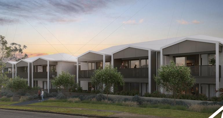
Company: Benson McCormack Architecture Role: CC Packages - Full Information Displayed : Ground Floor Plan, Wet Area Details.
Affordable Housing Bellingen, NSW.
19
GSPublisherVersion 2016.0.1.22 Description Date Rev For Information For CoordinationFor CoordinationFor ConstructionFOR TENDER NOT Preliminary for For structural coordination Issue for coordination Issue for coordination PRELIMINARY CCIssued for Construction 17 04 2023 17 04 2023 17 04 2023 05 2023 22 06 2023 13 09 2023 31 10 2023 11 2023 24 11 2023 12 2023 01 02 03 04 05 08 09 10 11 12 P 61 9818 0777 61 9818 0778 STUDIO 505 BALMAIN RD LILYFIELD NSW 2040 ABN 76 129 130 285 Nominated Architect RN David Benson NSW ARB 7285 2141A DRAWING DRAWN SCALE APPROVED STATUS PROJECT No DRAWING TITLE PROJECT DETAILS BELLORANA 1 100 CC A-110 JE DB BCA CONSULTANT PCA FIRE ENGINEER CLIENT VPL CONSULTING PO Box 2340 Burwood North NSW 2134 0410 667 020 XXXX Address Phone Web Site02 9715 2555 elitecertification E enquiries@bensonmccormack com bensonmccormack com W ELECTRICAL ENGINEER CENTRIC BUILDING SERVICES ENGINEERS Suite 401 Pacific Highway Artarmon NSW 2064 02 9052 6460 centricengineers NOTES LANDSCAPE ARCHITECT 30 Orlando Coffs Harbour NSW 2450 02 6651 7666 geolink net AMENDMENTS Suite Level 12 Park Street Sydney NSW 2000 02 8031 3200 www rfbi com au 15-23 Watson St Bellingen LEGEND Ground Floor Plan BED BTH K D LD 1 33 TGSI 10 11 12 13 14 15 16 17 UP G 56 56 56 W 1 01 G 56 G 56 56 D 11 W 01 W 01 D 32 1 33 D 35 1 70 70 D 70 1 70 35 D 70 70 70 D 1 72 D 1 71 D 1 72 D 73 D 73 D 1 73 W 02 LV 01 D 1 72 D 10 D 73 D 71 D 73 D 1 72 11 1 70 70 rwo fw fw fw FW fw FW fw fw FW fw fw fw fw GPO GPO GPO GPO GPO GPO GPO GPO fw rwo CO CO fw fw fw FW fw fw FW B A-130-001 A A-130-001 BLD2 A-540-001 D-09 A-710-006 D-17 A-710-006 WS4 -530-006 WS5 -530-008 E3 -120-002 W3 A-120-002 E A-130-002 WS1 -530-001 WS3 A-530-004 WS2 A-530-003 2,300 160 1,330 630 600 4,070 2,000 6,945 6,970 6,445 6,120 6,445 6,970 6,945 3,790 4,990 2,700 4,450 3,800 1,560 FFL 15.50 FFL 15.50 FFL 15.50 FFL 15.50 FFL 15.50 FFL 15.50 FFL 15.50 SSL 13.55 SSL 13.85 13.12 RL 13.85 RL 13.85 PROV. FOR FUTURE AC FUTURE AC AC FUTURE AC PROV. FOR AC PROV. FOR FUTURE AC 10 01 5 00 A 6 01 DP DP DP DP DP DP DP DP DP DP DP DP DP DP DP DP DP DP DP DP DP DP DP DP DP DP DP DP DP TOW 16 53 TOW 16 53 TOW 16 25 TOW 14 10 HANDRAIL AS PER FIRE EGRESS REQUIREMENTS HANDRAIL AS PER FIRE EGRESS REQUIREMENTS 00 11 16 10 11 11 01 01 51 20 OFDP OFDP DPOF DPOF WATSON STREET LIFT 1 6000 @ 1 20 15 00 13 850 179O17 00" 85 885m 1 95 O53 3 0 " | 26 21 m 175O 26' 00" | 12 27 m 1 1 O 01 45 " | 28 68 m SMOKE DOORS ON HOLD OPEN SYSTEM TRIP OFF BY SMOKE ALARM hyd hyd hyd FIP L BED BTH K D LD hyd BTH R C > 50 C R 50 DISCONTINUOUS R > 50 50 50 50 50 R 50 25 25 25 R 25 25 25 25 25 R 25 R 25 25 FENCE ON TOP OF RETAINING WALL RETAINING WALL FENCE ON TOP OF RETAINING WALL REFER TO LANDSCAPE PLAN FOR DETAILS REFER TO LANDSCAPE PLAN FOR DETAILS REFER TO LANDSCAPE PLAN FOR DETAILS REFER TO LANDSCAPE PLAN FOR DETAILS REFER TO LANDSCAPE PLAN FOR DETAILS hyd hyd hyd hyd hyd hyd hyd hyd hyd hyd hyd meter BUILDING SIGNAGE 1375 14 1425 145 16 75 16 5 17 1575 15 75 16 16 15 1625 16 25 15 25 1475 16 24 15 76 15 72 15 59 15 47 15 44 15 07 15 90 15 99 16 06 16 13 16 30 16 36 145 1575 1575 155 15 5 16 19 15 51 15 28 15 04 14 88 14 78 14 59 14 42 16 50 16 38 14 33 1463 14 26 16 44 15 66 15 68 15 73 15 31 15 14 14 46 14 26 14 03 14 36 P L BED BTH K D LD L BED BTH K D LD L BED BTH K D LD L BED BTH K D LD L BED BTH K D LD L BED BTH K D LD L BED BTH K D LD L BED BTH K D LD L BED BTH K D LD BTH S P S P S P S O P STRIP DRAIN PLANT MSB ROOM S P FALL 1 : 10 0 FALL 1 : 10 0 FALL 1 : 10 0 FALL 1 10 0 FALL 1 : 10 0 FALL 1 : 10 0 FALL 1 : 10 0 FALL 1 : 10 0 FALL 1 10 0 FALL 1 : 10 0 FALL 1 : 10 0 STAGE 2 BIN ROOM S P R -/120 120 KERB KERB 1 8 ROLLER DOOR KERB KERB INTERCOM 1:100 1:100 1:100 1:100 COMMS ELEC STRIP DRAIN FALL 1 : 80 INTERCOM MAIL SLAB EDGE SLAB EDGE SLAB EDGE SLAB EDGE 25 + C 25 STRIP DRAIN 101 BR A 50 1 m 102 BR 50 0 m 105 BR 50 0 m 104 BR 50 0 m 103 BR A 50 0 m 106 BR 50 0 m 107 BR 50 0 m 108 BR A 50 0 m 111 BR A 50 0 m 110 BR A 50 1 m 109 BR 50 0 m D 1 80 OFF SMOKE PUSH BUTTON TO 2 1 70 70 FF00 1 57 57 1 57 1 57 1 57 F A-130-002 FF103 FF10 FF10 FF104 FF003 FF103 FF10 FF10 FF104 FF003 FF103 FF10 FF10 FF104 FF003 FF103 FF10 FF104 FF10 FF003 FF10 FF10 FF10 FF003 FF103 FF003 FF103 FF10 FF10 FF104 FF103 FF104 FF10 FF10 FF003 FF103 FF104 FF10 FF10 FF003 FF103 FF10 FF104 FF10 FF003 FF103 FF10 FF10 FF105 FF003 FF103 FF10 FF104 FF003 FF002 FF00 FF00 FF10 FF002 EFX002 EFX002 EFX002 FF000 FF10 FF 00 F00 EFX 00 5 FF10 FF10 FF10 FF10 FF10 FF10 F F G G H H I I J J K K L L M M N N 1 3 4 5 6 7 fw FW FW LV 01 1 90 FNC1 A-550-001 1 A-580-001 D-13 A-710-006 300 5,890 815 5,000 3,080 515 300 4,400 815 FFL 15.50 E2 A-120-002 Hyd Hyd 23 01 BLD-02 11 10 51 51 51 51 51 51 51 BLD02 BLD-02 BLD02 BLD-02 BLD02 5 00 A 00A 6 11 16 10 16 10 6 19 11 6 11 6 11 16 10 6 11 5 10 00 6 53 6 53 BLD02 BLD02 BLD-02 BLD-02 BLD-023 33 6 11 6 01 16 10 6 11 6 11 16 10 30 BLD-02 BLD-02 01 53 53 6 53 1 11 15 11 6 11 10 16 11 16 6 01 OVER UNDER 01 OVER 10 UNDER REFER TO MECH DRAWINGS K-01 R-01 -01 R-01 R-01 R-01 R-01 -01 -01 -01 R-01 -01 R-01 K-01 K-01 K-01 K-01 K-01 K-01 -01 -01 -01 23 10 UNDER BED BED FF10 FF002 FF102 EFX002 1 All drawings to AHD Australian Height 2 Read in conjunction with Structural and Fire Engineers drawings and arborist 3 Slabs and columns shown are indicative drawings and architectural concrete Engineer if there are any discrepancies 4 All car parking areas to be min H2200 AS1428 5 All disabled car parking spaces to be AS2890 AS1428 1 6 All basement carparks to have 1 100 comply with Australian Standards ROOMS BED Bedroom 1 Bedroom 2 BT Bathroom 1 Bathroom K Kitchen Living D Dining LD Laundry Pantry R Robe Storage SD Study WC Toilet HYDRAULIC SERVICES Basin BT Boundary Trap CO Clean Out FH Fire Hydrant FHB Fire Hydrant Boundary FHS Fire Hydrant Supply FE Fire Extinguisher FW Floor Waste HT Hose Tap HYD Attack Hydrant IO Inspection Opening OF Overflow ORG Overflow Relief Gul y SD Sprinkler Dropper SK Sink EQUIPMENT Refridgerator Oven WM Washing Machine CIVIL STORMWATER DP Downpipe FG Floor Grate OFFG Overflow Flo Grate OF Overflow PG Planter Grate RWO Rainwater Outlet SPB Suspended Planter Box RWO VD Vertical Drop SERVICES AC Air Conditioning CPE Car Park Exhaust + Electrical Communications FE Fire Extinguisher FH Fire Hydrant FHR Fire Hose Reel FHB Fire Hydrant Booster FHS Fire Hydrant Supply FIP Fire Indicator Panel GE Garbage Exhaust GM Gas Meters HYD Hydrant MIMIC MIMIC Panel PP Private Pillar electrical WMC Water Meters Cupboard GENERAL BP01 Bicycle Parking 01 TPZ Tree Protection Zone Tree 1 1GROUND Scale 1 100 FOR FIXTURES AND FINISHES REFER TO FF&E SCHEDULE BUILDING 2 NOT ASSESSED UNDER THIS CC Ground Floor Plan 20

GSPublisherVersion 2016.0.1.22 Description Date Rev FOR TENDER NOT FOR CONSTRUCTION Issue for coordinationIssued for Construction CC22 2023 31 2023 12 2023 01 02 04 P + 61 9818 0777 F + 61 9818 0778 STUDIO 505 BALMAIN RD LILYFIELD NSW 2040 ABN 76 129 130 285 Nominated Architect RN David Benson NSW ARB 7285 2141A DRAWING No DRAWN BY SCALE APPROVED STATUS PROJECT No DRAWING TITLE PROJECT DETAILS ** BEFORE YOU DIG** byda BELLORANA 1 20 CC A-622-001 JE DB BCA CONSULTANT STRUCTURAL ENGINEER PCA FIRE ENGINEER CIVIL ENGINEER HYDRAULIC ENGINEER CLIENT VPL CONSULTING PO Box 2340 Burwood North NSW 2134 XXXX Address ELITE CERTIFICATION Suite Level -17 Elsie St Burwood NSW 2134 02 9715 2555 LINDSAY & ASSOCIATES Suite 1075 Old Princes 0411 041 242 lindsayassociates Highway 02 9052 6460 centricengineers E enquiries@bensonmccormack com www bensonmccormack com W ELECTRICAL ENGINEER MECHANICAL CENTRIC BUILDING SERVICES ENGINEERS Suite 401 Pacific Highway Artarmon NSW 2064 02 9052 6460 centricengineers CENTRIC BUILDING SERVICES Suite 401 Pacific Highway 02 9052 6460 www centricengineers NOTES LANDSCAPE ARCHITECT ACOUSTIC ENGINEER GeoLINK 30 Orlando Coffs Harbour NSW 2450 geolink Company Name Address Web Site AMENDMENTS Sydney 02 8031 3200 rfbi 15-23 Watson St Bellingen NSW McCORMACK ARCHITECTURE LEGEND Wet Area Details - Apt Type 01 CENTRIC BUILDING SERVICES Suite 401 Pacific Highway centricengineers Rev Date Description DP Full Name Reg No 04 5 12 2023 Issued for Construction CC-04 David Benson DEP0000579 Drawing Drawing - Apt Type 01 500 500 1,200 1,200 1,200 1,000 450 WC 610 1,652 1 2 3 4 A FX118 10a 6 16 6 16 hyd fw FW FW 1000 SHOWER 1,000 FX120 FX133 FX119 FX133 FX121 Ply bracing for walls where indicated FX132 FX131 FX128 WATERSTOP ANGLE WATERPROOFING AS PER THE WATERPROOFING REPORT SPECS BATH LD S 1:80 1:80 1:80 1:80 1:80 1:80 1:80 FX111 1:80 1:80 FALLS WPM 01 WPM 01 C L EFX002 - Green Hatch indicates area required proofed to comply with NCC 2022 Vol RWO - Rain Water Outlet R - Robe LD - Laundry - Provide ply bracing FW - Floor Waste S - Storage P - Pantry F - Fridge - Light Fixture D 72 hyd fw FW FW 1:80 1:80 1:80 1:80 1:80 1:80 1:80 1:80 1:80 FALLS WPM 01 WPM 01 200 Eq. Eq. 2,100 SHOWER CURTAIN HEIGHT 2,400 2,000 150 F.C.L F.F.L 2,000 WATERPROOFING FX118 FX121 FX120 WF105 WF102 FX131 450 MOISTURE RESISTANT PLASTERBOARD SHOWER CURTAIN 2,400 150 600 2,400 F.C.L F.F.L MOISTURE RESISTANT PLASTERBOARD FX131 WF102 WF105 FX118 FFL 1,800 WALL TILE HEIGHT 150 900 1,800 WATER PROOFING 2,100 2,400 610 900 FX119 150 F.C.L F.F.L 1,710 WATERPROOFING MOISTURE RESISTANT PLASTERBOARD WF102 FX122 WF102 WF105 FX121 FX120 150 SHOWER CURTAIN FX119 C L 1TYPICAL BATH Scale 1 20 1WATERPROOFING AREA PLAN Scale 1 20 3TYP BATH ELEV 03 Scale 1 20 2TYP BATH ELEV 02 Scale 1 20 4TYP BATH ELEV 04 Scale 1 20 **NOTE 1 TYPICAL BATHROOM LAYOUT ARE IN RELATION TO THE FFE SELECTION AND PLACEMENT THE OVERALL ROOM SIZE CAN VARY SLIGHTLY BETWEEN APARTMENTS ALWAYS READ IN CONJUNCTION WITH THE A-0100 AND A-620-001 DRAWING THE WET AREA SET DOWNS IN THE CONCRETE PROFILES ARE UNIQUE TO EACH BATHROOM 2 REFER TO THE FFE DOCUMENT FOR FIXTURE SELECTIONS AND DETAILS 3 MUST BE CONSTRUCTED IN ACCORDANCE WITH THE NCC2022 AND AS3740 4 MUST BE READ IN CONJUNCTION WITH DETAIL ON A624-001 5 MUST BE READ IN CONJUNCTION WITH THE WATERPROOFING REPORT GOLD LIVABLE UNIT DESIGN 1 - Appropriate 1200mm clearances throughout the unit are require allowing suitable accessible paths of travel 2 - All internal doors are required to achieve 850mm open clear widths 3 - Units require bathrooms that can accommodate the required 1200mm wide by 1200mm long clear visitable toilet circulation space in front of the leading edge of the pan The pan is to be in the corner of the room for future provisions of grab rails 4 - Units require a hobless shower recess of 900mm x 900mm and clear space of 1200mm 1200mm forward of the shower recess entry TAKEN FROM WATERPROOFING CONSULTNAT DOCS REV 0 F.C.L F.F.L MOISTURE RESISTANT PLASTERBOARD FX128 WF105 FX122 900 FX119 2,400 1,200 FX132 150 FFL FX119 WF102 FX134 FX132 1TYP BATH ELEV 01 Scale 1 20 Wet Area Details 21
PAGE HAS BEEN INTENTIONALLY LEFT BLANK
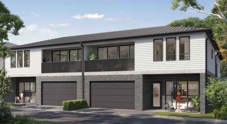
Seniors Living - Mount Gilead Estate
Class 2 Retirement Villas at Gilead, NSW.
Company: Benson McCormack Architecture
Role: Construction Documentation - GAs, Elevations, Sections, Concrete Profiles, Wall Type Details, Wall Setouts, Wall Section Details.
Information Displayed : Ground Floor Plan, Level 1 Plan, Elevation, Wall Section.
22
of
Property
BMA
Ground Floor Plan
Worked on documenting General Arrangement Drawings and other CC packages. Floor Plan shows a module which are multiplied on a masterplan scale.
LEGEND AC Air Conditioning ACC Accessible ADP Adaptable AH Access Hatch AHD Australian Height AL Aluminium AMB Ambulant AWN Awning B1,2 Bedroom 1,2 etc BAL1,2 Balustrade 1,2 etc BG Box Gutter BKP Bicycle Parking BLK Blockwork BL Bollard BT1,2 Bathroom 2 etc BRWO Balcony Rain Water BWK Brickwork BY Balcony CAP Capping CBF Concrete Broom Finish CEA Concrete Exposed CFC Compressed Fibre CFF Concrete Float Finish CGF Concrete Groove Finish CTFF Ceramic Tile Floor CHS Circular Hollow Section CIS Cistern CJ Construction Joint CL Centre Line CLD Cladding CLNR Cleaner Store CONC Concrete COF Concrete Off-Form COL Column COM Commercial COMS Communications Services COS Check on Site CPE Car Park Exhaust CPC Concrete Precast CPD Cupboard CPT Carpet CSF Cementitious Screed CST Concrete Steel Trowel CMR Cement Render CY Courtyard CWB Car Wash Bay CWS Cold Water Supply D Dining DB Distribution Board DG Drip Groove DP Down Pipe DRY Dryer DW Dishwasher E Entry EFF Epoxy Floor Finish EJ Expansion Joint ELEC Electrical Services EN Ensuite EX Existing EXJ Expressed Joint EXH Exhaust F Fire Services FCC Fire Control Centre FCR Fire Control Room FEX Fire Extinguisher FFL Finished Floor Level FH Fire Hydrant FHR Fire Hose Reel FIP Fire Indicator Panel FLS Flashing FMP Fire Mimic Panel FN 1,2 Furniture Type 1 FEP 1,2 Fire Egress Passage FRL Fire Resistance Level FS 1,2 Fire Stair No etc FW Floor Waste GB Gas Bayonet GBC Garbage Chute GBR Garbage Room GDR Grated Drain GEX Garbage Exhaust GHR Garbage Holding Room GPT Gross Pollutant Trap GAL Galvanised GVL Gravel H Hydraulic Services HP High Point HR Handrail HRV Heavy Rigid Vehicle 1 All drawings to AHD Australian 2 Read in conjunction with Geotechnical Engineers information 3 Slabs and columns shown are drawings and architectural concrete Engineer if there are any discrepancies 4 All car parking areas to be min AS1428 5 All disabled car parking spaces AS2890 AS1428 6 All basement carparks to have comply with Australian Standards Concrete Off Form - Natural Finish COF Palisade Fence - Powdercoated Finish FN1 Selected Powercoat Finish PCF PNF Selected Paint Render Finish TLF Selected Internal Floor Tiles Slip Resistant CLD1 Selected Fibre Cement - Acrylic Rendered Finish BAL Concrete Upturn Balustrade - Acrylic Rendered Finish SC1 Fixed Privacy Screen - Powercoated Finish 1 All drawings use the Units shown on the Key Plan as a template The rest of the units follow the same construction methodology The FFLs vary as noted on the Concrete Setout Information 2 Read in conjunction with Geotechnical Structural Mecahnical Hydraulic Engineer s information and Interior Architect Finishes and Purchaser Changes Schedules Slabs and columns shown are indicative refer to Structural Engineer drawings and architectural concrete profiles Notify BMA and Structral Engineer if there are any discrepancies between these drawings 4 Refer to the following but not limited to A Refer to BCA BASIX Fire Engineering Bush Fire Access and Acoustic Reports for various specific requirements B Refer to concrete outline plans & reflected ceiling plans for window and ceiling interfaces C Refer to architectural drawings to ascertain surrounding wall type thickness and materials D Refer to external materials and finishes schedule E Refer to specifications 5 Window sills & rebated panels fall to outside 6 Sub-sills and sub-heads not shown for clarity 7 Colour to all aluminium capping to match window frame 8 Refer to manufacturers details and specification for al selected cladding and paint finishes 9 Wall type tags and left of the GA Plans Refer to Wall Setout Plans for all details relating to walls WB1 Selected Weatherboard Cladding light colour TLF Selected Carpet - To Interior Architect Specification CPT IM Selected Timber Look - Hybrid Hard Flooring Selected External Floor Tiles Slip Resistant WB2 Selected Weatherboard Cladding dark colour SK1 Selected Skylight Facebrick light colour B1 Facebrick darker colour FB2 D1 01 D1 01 D1 01 D1 01 G2 08 G2 02 G2 01 G2 07 G2 06 G 2 05 D 1 04 D 1 04 D 1 04 D1 05 D 1 05 D 1 02 D 1 02 D1 03 D1 03 D1 05 G2 08a G2 02a G2 01a G2 07a G2 06a G 2 05 D 1 04 D 1 04 D1 05 D 1 05 D1 03 D1 03 D 1 04 D1 05 G2 08 G 02 G2 01 G2 07 G2 06 G 2 05 D 1 04 D 1 04 D 1 04 D1 05 D 1 05 D 1 02 D 1 02 D1 03 D1 03 D1 05 G2 08a G2 02a G2 01a G2 07a G2 06a G 2 05 a D 1 04 D 1 04 D 05 D 1 05 D1 03 D1 03 D 1 04 D1 05 F F HWU F F 01 A-0777 05 A-0753 2,000 23,900 1,500 11,500 11,500 11,500 11,500 2,000 9,530 4,250 10,120 1,500 23,900 46,000 A -0300 A -0300 C -0301 C -0301 B -0300 B A-0300 D -0301 D A-0301 E -0302 E A-0302 N A-0200 E A-0201 S A-0200 W -0201 S1 -0202 N1 A-0202 PROVISION FOR RETRACTABLE CLOTHESLINE PROVISION FOR RETRACTABLE CLOTHESLINE LINE OF SLAB OVERHANG ABOVE LINE OF SLAB OVERHANG ABOVE LINE OF SLAB OVERHANG ABOVE LINE OF SLAB OVERHANG ABOVE LOCKED GATE ACCESS BY SERVICES PERSONNEL ONLY LOCKED GATE ACCESS BY SERVICES PERSONNEL ONLY UNIT 100 UNIT 102 UNIT 104 UNIT 106 HT HT HT HT SC 2 01 02 01 02 01 02 01 02 DR DW DW DR DW DW WM DR WM DR A A B B 2 2 C C D D E E 1 1 5 5 6 6 3 3 4 4 G2 03 G2 04 G2 03a G2 04a D1 03 G2 03 G2 04 G2 03 G2 04a D1 03 01 A-0772 01 A-0770 01 A-0753 03 A-0753 04 A-0753 05 A-0753 02 A-0753 01 A-0776 01 A-0771 01 A-0773 DRIVEWAY LANDSCAPING DRIVEWAY LANDSCAPING DRIVEWAY LANDSCAPING DRIVEWAY LANDSCAPING WAKWAY WAKWAY WAKWAY WAKWAY LINEN ENTRY VERANDAH COURTYARD LAUNDRY ZONE FOR ADDITIONAL STORAGE BY OTHERS TFL2 TIM CPT OFC TFL1 TFL1 CPT CPT 1M CLEAR WIDE SERVICES VOID ACCESS FOR AUTHORISED PERSONNEL ONLY AC AC ENTRY VERANDAH COURTYARD LAUNDRY ZONE FOR ADDITIONAL STORAGE BY OTHERS TFL2 TIM CPT TFL1 TFL CPT CPT LINEN FENCE SC 1 OFC TFL TFL TFL1 TFL1 TFL DP DP DP DP DP DP DP DP DP DP DP SLIP RATING DP DP LINEN ENTRY VERANDAH COURTYARD LAUNDRY ZONE FOR ADDITIONAL STORAGE BY OTHERS TFL TIM CPT OFC TFL1 TFL1 CPT CPT M CLEAR WIDE SERVICES VOID ACCESS FOR AUTHORISED PERSONNEL ONLY AC AC ENTRY VERANDAH COURTYARD LAUNDRY ZONE FOR ADDITIONAL STORAGE BY OTHERS TFL TIM CPT TFL1 TFL CPT CPT LINEN FENCE SC 1 OFC TFL TFL TFL1 TFL1 TFL DP DP DP DP DP DP DP DP DP DP DP SLIP RATING DP DP HT HT HT HT ST ST ST ST DP DP DP DP DP DP DP DP DP DP DP DP DP DP DP DP BED 2 A 12 3 m ENSUITE m BED 3/ST A 13 m DINING LIVING BED 1 A 17 m BATH A 10 m KITCHEN COURTYARD A 26 6 m GARAGE A 36 0 m ENS A 5 m COURTYARD A 26 m ENSUITE A 7 3 m BED 3/ST A 13 m BED 1 A 17 m KITCHEN DINING LIVING BED 2 19 0 m WIR 7 1 m WIR 7 m GARAGE A 36 0 m BATH A 8 m BED 2 12 3 m ENSUITE A 7 3 m BED 3/ST A 13 m DINING LIVING BED 1 17 9 m BATH A 10 m KITCHEN COURTYARD 26 6 m GARAGE 36 0 m ENS A m COURTYARD A 26 m ENSUITE m BED 3/ST A 13 m BED 1 A 17 m KITCHEN DINING LIVING BED 2 A 19 0 m WIR 7 m WIR 7 1 m GARAGE 36 0 m BATH A m 4 4 01 GROUND (TERRACE) - GENERAL ARRANGEMENT PLAN TYPICAL FOR UNITS 100 102, 104, 106, 108, 110, 112, 114 116, 118, 120, 122 254, 256, 258, 260, 262, 264, 266 268, 270, 272, 274 276 1:100 FLOOR PLAN ARRANGEMENT IS TYPICAL FOR ALL LOTS REFER TO KEY PLAN STUDIO 505 BALMAIN RD LILYFIELD NSW 2040 ABN 76 129 130 285 RN 7536 2135A SCALE STATUS PROJECT No DRAWING TITLE PROJECT DETAILS approval prior to construction Do not scale drawings Check Inconsistencies are to be ** DIAL ALL WORKS TO COMPLY AUSTRALIA BCA MOUNT GILEAD 1 100 CC CD KEY PLAN AMENDMENTS 72 GLENDOWER INTERIOR ARCHITECT BCA NCC CONSULTANT FIRE ENGINEER CLIENT ELECTRICAL ENGINEER BUSHFIRE CONSULTANT HT BUILDING 72 GLENOWER STREET GILEAD NSW Design By KMC Mosman NSW 61 418591017 designbykmc com Custom Development Certifications Level 25 Aurora Place 88 Phillip St NSW 2000 61 02 72287901 Building Engineers Level 121 Walker St North Sydney 02 9922 5200 www bse com au E Mobius Fire Safety Pty Ltd Suite Argyle Street Camden 61 52662487 www mobiusfire com au Travers Bushfire and Ecology Francis Byrnes Road Jilliby NSW 2570 www traversecology com au Description Date Rev ISSUE ISSUE UPDATED ISSUE CONSTRUCTION CONSTRUCTION CONSTRUCTION 12 2021 10 12 2021 24 01 2022 29 04 2022 24 05 2022 08 2022 02 03 04 Rev Date Description Revision ID Revision ID 4 4 08 2022 CONSTRUCTION REVISION 4 4 Change Name DOOR CHANGE WALL TYPE CHANGE JOINERY REVISED Project Title: MOUNT GILEAD ESTATE - STAGE 4 VILLAS LOT & DP No Lot 2 DP 1065919 Consent No 2828 2005/DA-SL/D Drawing No A-0101 Drawing Title GA - GROUND FLOOR PLAN TERRACEMODULE A 23
First Floor Plan 1 All drawings to AHD Australian 2 Read in conjunction with Geotechnical Engineers information 3 Slabs and columns shown are drawings and architectural concrete Engineer if there are any discrepancies 4 All car parking areas to be min AS1428 5 All disabled car parking spaces AS2890 AS1428 6 All basement carparks to have comply with Australian Standards LEGEND AC Air Conditioning ACC Accessible ADP Adaptable AH Access Hatch AHD Australian Height AL Aluminium AMB Ambulant AWN Awning B1,2 Bedroom 1,2 etc BAL1,2 Balustrade 1,2 etc BG Box Gutter BKP Bicycle Parking BLK Blockwork BL Bollard BT1,2 Bathroom 2 etc BRWO Balcony Rain Water BWK Brickwork BY Balcony CAP Capping CBF Concrete Broom Finish CEA Concrete Exposed CFC Compressed Fibre CFF Concrete Float Finish CGF Concrete Groove Finish CTFF Ceramic Tile Floor CHS Circular Hollow Section CIS Cistern CJ Construction Joint CL Centre Line CLD Cladding CLNR Cleaner Store CONC Concrete COF Concrete Off-Form COL Column COM Commercial COMS Communications Services COS Check on Site CPE Car Park Exhaust CPC Concrete Precast CPD Cupboard CPT Carpet CSF Cementitious Screed CST Concrete Steel Trowel CMR Cement Render CY Courtyard CWB Car Wash Bay CWS Cold Water Supply D Dining DB Distribution Board DG Drip Groove DP Down Pipe DRY Dryer DW Dishwasher E Entry EFF Epoxy Floor Finish EJ Expansion Joint ELEC Electrical Services EN Ensuite EX Existing EXJ Expressed Joint EXH Exhaust F Fire Services FCC Fire Control Centre FCR Fire Control Room FEX Fire Extinguisher FFL Finished Floor Level FH Fire Hydrant FHR Fire Hose Reel FIP Fire Indicator Panel FLS Flashing FMP Fire Mimic Panel FN 1,2 Furniture Type 1 FEP 1,2 Fire Egress Passage FRL Fire Resistance Level FS 1,2 Fire Stair No etc FW Floor Waste GB Gas Bayonet GBC Garbage Chute GBR Garbage Room GDR Grated Drain GEX Garbage Exhaust GHR Garbage Holding Room GPT Gross Pollutant Trap GAL Galvanised GVL Gravel H Hydraulic Services HP High Point HR Handrail HRV Heavy Rigid Vehicle Concrete Off Form - Natural Finish COF Palisade Fence - Powdercoated Finish FN1 Selected Powercoat Finish PCF PNF Selected Paint Render Finish TLF Selected Internal Floor Tiles Slip Resistant CLD1 Selected Fibre Cement - Acrylic Rendered Finish BAL Concrete Upturn Balustrade - Acrylic Rendered Finish SC1 Fixed Privacy Screen - Powercoated Finish 1 All drawings use the Units shown on the Key Plan as a template The rest of the units follow the same construction methodology The FFLs vary as noted on the Concrete Setout Information 2 Read in conjunction with Geotechnical Structural Mecahnical Hydraulic Engineer s information and Interior Architect Finishes and Purchaser Changes Schedules Slabs and columns shown are indicative refer to Structural Engineer drawings and architectural concrete profiles Notify BMA and Structral Engineer if there are any discrepancies between these drawings 4 Refer to the following but not limited to A Refer to BCA BASIX Fire Engineering Bush Fire Access and Acoustic Reports for various specific requirements B Refer to concrete outline plans & reflected ceiling plans for window and ceiling interfaces C Refer to architectural drawings to ascertain surrounding wall type thickness and materials D Refer to external materials and finishes schedule E Refer to specifications 5 Window sills & rebated panels fall to outside 6 Sub-sills and sub-heads not shown for clarity 7 Colour to all aluminium capping to match window frame 8 Refer to manufacturers details and specification for al selected cladding and paint finishes 9 Wall type tags and left of the GA Plans Refer to Wall Setout Plans for all details relating to walls WB1 Selected Weatherboard Cladding light colour TLF Selected Carpet - To Interior Architect Specification CPT IM Selected Timber Look - Hybrid Hard Flooring Selected External Floor Tiles Slip Resistant WB2 Selected Weatherboard Cladding dark colour SK1 Selected Skylight Facebrick light colour B1 Facebrick darker colour FB2 G2 12 S 150 G 2 16 S 900 G2 12 S 150 G 2 11 S 200 G 2 17 S 1 500 G 2 10 D 1 04 D 1 03 D 1 04 D1 04 G2 12 S 150 G 2 16 S 900 G2 12 150 G 2 11 S 200 G 2 17 S 1 500 G 2 10 D1 04 D 1 04 D 1 03 D 1 04 D1 04 D1 05 D1 04 D1 05 G2 14 S 500 G2 14 S 500 G2 14 S 500 G2 12 S 530 G 2 16 S 700 G2 12 S 3 530 G 2 11 S 0 G 2 17 S 1 300 G 2 10 D 1 04 D 1 03 D 1 04 D 04 G2 12 S 3 530 G 2 16 S 700 G2 12 530 G 2 11 S G 2 17 S G 2 10 D1 04 D 1 04 D 1 03 D 1 04 D1 04 D1 05 D1 04 D1 05 G2 14 300 G 14 300 G2 14 S 300 G 2 13 S 1 500 G 2 13 S 1 300 F F F F A -0300 A -0300 C -0301 C -0301 B -0300 B A-0300 D -0301 D A-0301 E -0302 E A-0302 N A-0200 E A-0201 S A-0200 W -0201 S1 -0202 N1 A-0202 2,000 23,900 1,500 27,400 46,000 11,500 11,500 11,500 11,500 BAL 1 BAL BAL BAL SC SC 1 BAL BAL BAL BAL SC 1 SC FIRE RATED WINDOWS AROUND COURTYARD 01 02 01 02 01 02 01 02 DW DW DR DW DR DW DR DR A A B B 2 2 C C D D E E 1 1 5 5 6 6 3 3 4 4 D1 01 G2 15 G2 15 D1 01 G2 15 G2 15 G2 14 S 500 G2 14 S 500 G2 14 S 500 D1 01 G2 15 G2 15 D1 01 G2 15 G2 15 G2 14 300 G2 14 S 300 G2 14 300 01 A-0774 01 A-0775 02 A-0776 01 A-0778 05 A-0753 06 A-0753 LINE INDICATES ROOF EDGE ABOVE LINE INDICATES ROOF EDGE ABOVE UNIT 601 UNIT 603 UNIT 605 UNIT 607 LINEN COURTYARD BELOW COURTYARD BELOW ENTRY LANDSCAPING DRIVEWAY LAUNDRY JOINERY ZONE FOR ADDITIONAL STORAGE BY OTHERS BALCONY ENTRY BALUSTRADE TO DETAIL GATE GATE STORAGE NICHE PRIVACY WALL LINEN COURTYARD BELOW COURTYARD BELOW LANDSCAPING DRIVEWAY LAUNDRY JOINERY ZONE FOR ADDITIONAL STORAGE BY OTHERS BALCONY ENTRY LOWER WALL BELOW SKYLIGHT ABOVE PANTRY STORE STORAGE NICHE SKYLIGHT ABOVE PANTRY STORE SKYLIGHT ABOVE SLIP RATING TFL3 OFC CPT TFL TFL2 TFL1 CPT CPT OFC CPT TFL1 TFL TFL1 CPT CPT TIM TIM RATING DEEPER SOIL DEEPER SOIL ENTRY DP DP DP DP DP DP DP DP DP DP DP DP DP HT HT LINEN COURTYARD BELOW COURTYARD BELOW ENTRY LANDSCAPING DRIVEWAY LAUNDRY OINERY ZONE FOR ADDITIONAL STORAGE BY OTHERS BALCONY ENTRY BALUSTRADE TO DETAIL GATE GATE STORAGE NICHE LINEN COURTYARD BELOW COURTYARD BELOW LANDSCAPING DRIVEWAY LAUNDRY OINERY ZONE FOR ADDITIONAL STORAGE BY OTHERS BALCONY ENTRY LOWER WALL BELOW SKYLIGHT ABOVE PANTRY STORE STORAGE NICHE SKYLIGHT ABOVE PANTRY STORE SKYLIGHT ABOVE SLIP RATING TFL3 OFC CPT TFL TFL2 TFL CPT CPT OFC CPT TFL1 TFL TFL CPT CPT TIM TIM DEEPER SOIL DEEPER SOIL ENTRY DP DP DP DP DP DP DP DP DP DP DP DP DP HT HT SLIP RATING TFL SLIP RATING TFL DIRECTIONAL PRIVACY SCREEN BALUSTRADE TO DETAIL DIRECTIONAL PRIVACY SCREEN DIRECTIONAL PRIVACY SCREEN BALUSTRADE TO DETAIL DIRECTIONAL PRIVACY SCREEN DP DP DP DP DP DP DP DP GARAGE 41 0 m BED 1 17 3 m WIR A 5 1 m ENSUITE 6 9 m BED 2 13 1 m BED 3/ST A m BATH A 7 9 m TERRACE A 40 3 m DINING LIVING GARAGE A 41 m BED 1 A 17 BED 2 A 13 3 m BED 3 A m BATH 7 m TERRACE A 40 3 m KIT LIVING WIR 5 m ENSUITE A m DINING KIT GARAGE A 41 m BED 1 A 17 m WIR A m ENSUITE 6 m BED 2 A 13 1 m BED 3/ST A 9 4 m BATH A m TERRACE A 40 3 m DINING LIVING GARAGE 41 0 m BED 1 17 2 BED 2 A 13 3 m BED 3 A m BATH A 7 9 m TERRACE 40 3 m KIT LIVING WIR A 5 0 m ENSUITE A 6 9 m DINING KIT 3 3 01 LEVEL 1 (HORIZON) - GENERAL ARRANGEMENT PLAN TYPICAL FOR UNITS 601 603, 605, 607, 609, 611, 613, 615 617, 619, 621, 623 101, 103, 105, 107, 109, 111, 113 115, 117, 119, 121 123 1:100 FLOOR PLAN ARRANGEMENT IS TYPICAL FOR ALL LOTS REFER TO KEY PLAN STUDIO 505 BALMAIN RD LILYFIELD NSW 2040 ABN 76 129 130 285 RN 7536 2135A SCALE STATUS PROJECT No DRAWING TITLE PROJECT DETAILS approval prior to construction Do not scale drawings Check Inconsistencies are to be ** DIAL ALL WORKS TO COMPLY AUSTRALIA BCA MOUNT GILEAD 1 100 CC CD KEY PLAN AMENDMENTS 72 GLENDOWER INTERIOR ARCHITECT BCA NCC CONSULTANT FIRE ENGINEER CLIENT ELECTRICAL ENGINEER BUSHFIRE CONSULTANT HT BUILDING 72 GLENOWER STREET GILEAD NSW Design By KMC Mosman NSW 61 418591017 designbykmc com Custom Development Certifications Level 25 Aurora Place 88 Phillip St NSW 2000 61 02 72287901 Building Engineers Level 121 Walker St North Sydney 02 9922 5200 www bse com au E Mobius Fire Safety Pty Ltd Suite Argyle Street Camden 61 52662487 www mobiusfire com au Travers Bushfire and Ecology Francis Byrnes Road Jilliby NSW 2570 www traversecology com au Description Date Rev ISSUE ISSUE UPDATED ISSUE CONSTRUCTION CONSTRUCTION 12 2021 10 12 2021 24 01 2022 29 04 2022 23 06 2022 02 03 04 Rev Date Description Revision ID Revision ID 3 4 08 2022 CONSTRUCTION REVISION 3 3 Change Name JOINERY REVISED GA - LEVEL 1 FLOOR - MODULE A Project Title: MOUNT GILEAD ESTATE - STAGE 4 VILLAS LOT & DP No Lot 2 DP 1065919 Consent No 2828 2005/DA-SL/D Drawing No A-0102 Drawing Title GA - LEVEL 1 FLOOR PLAN (HORIZON - MODULE A 24


Elevation AC Air Conditioning ACC Accessible ADP Adaptable AHD Australian Height Datum AL Aluminium AWN Awning 1,2 Bedroom Bedroom etc BAL Balustrade BG Box Gutter BLK Blockwork BL Bollard BT Bathroom BK Brickwork BALC Balcony CAP Capping CLD Cladding CJ Construction Joint CL Ceiling Level COF Off form Concrete COL Column CONC Concrete COMS Communications Services COS Communal Open Space CPE Car Park Exhaust CPC Concrete Precast CPD Cupboard CWB Car Wash Bay CWM Cold Water Meter CWS Cold Water Supply Dining DB Distribution Board DP Down Pipe ELEC Electrical Services EX Existing EXH Exhaust Fire Services FCC Fire Control Centre FCR Fire Control Room FEX Fire Extinguisher FFL Finished Floor Level FH Fire Hydrant FHR Fire Hose Reel FIP Fire Indicator Panel FLS Flashing FMP Fire Mimic Panel FRL Fire Resistance Level FS 01,02 Fire Stair No etc FW Floor Waste GBC Garbage Chute GBR Garbage Room TD Grated Drain GEX Garbage Exhaust GPT Gross Pollutant Trap GR Grab Rail Hydraulic Services HR Handrail HWM Hot Water Meter Hose Tap HWU Hot Water Unit IL Invert Level INS Insulation 01,02 Joinery Type 01 02 etc K Kitchen KB Kerb KEX Kitchen Exhaust 01,02 Lift No etc Living Living Dining LY Laundry LV Louvre M Mechanical Services MBP Motor Bike Parking MBX Mail Box MVJ Movement Joint MV Mechanical Vent MSB Main Switch Board Service MTR Meter NGL Natural Ground Level NOM Nominal OFS Over Flow Spout OSD On Site Detention Tank OSR On Site Retention Tank Pantry PCF Powdercoat Finish PF Paint Finish R Robe Recessed REF Refrigerant Pipe Riser REQS Requirements RWH Rain Water Head RWO Rainwater Outlet Storage SC teel Column SDO Spoon Drain Outlet R Structural Floor Level SIM Similar SKL Skylight SO Structural Opening SP Stair Pressurisation STL Steel ST 01 Stair No 1 etc STY Study SWD Stormwater Drain SWP Stormwater Pit Thermal TCE Terrace TGSI Tactile Ground Surface Indicator TOW Top of Wall TYP Typical UNO Unless Noted Otherwise U Underside UT Utility Space Void VS Visitor VP Vent Pipe WC Toilet WIR Walk in Robe Concrete Off Form - Natural Finish COF Palisade Fence - Powdercoated Finish FN1 Selected Powercoat Finish PCF PNF Selected Paint Render Finish TLF Selected Internal Floor Tiles Slip Resistant CLD Selected Fibre Cement - Acrylic Rendered Finish BAL Aluminium Balustrade - Powdercoated Finish BAL Concrete Upturn Balustrade - Acrylic Rendered Finish SC Fixed Privacy Screen - Powercoated Finish FIXTURES AND FINISHES All drawings use the Units shown on the Key Plan as template The rest of the units follow the construction methodology The FFLs vary as noted on the Concrete Setout Information Read in conjunction with Geotechnical Structural Mecahnical Hydraulic Engineer information and Interior Architect Finishes and Purchaser Changes Schedules Slabs and columns shown are indicative refer to Structural Engineer drawings and architectural concrete profiles Notify BMA and Structral Engineer there are any discrepancies between these drawings Refer to the following but not limited to A Refer to BCA BASIX Fire Engineering Bush Fire Access and Acoustic Reports for various specific requirements B Refer to concrete outline plans & flected ceiling plans for window and ceiling interfaces C Refer to architectural drawings to ascertain surrounding wall type thickness and materials D Refer to external materials and finishes schedule E Refer to specifications Window sills & rebated panels fall to outside Sub-sills and sub-heads not shown for clarity Colour to all aluminium capping to match window frame Refer to manufacturers details and specification for al selected cladding and paint finishes Wall type tags and left of the GA Plans Refer to Wall Setout Plans for all details relating to walls WB1 Selected Weatherboard Cladding light colour TLF Selected Carpet - To Interior Architect Specification CPT IM Selected Timber Look - Hybrid Hard Flooring Selected External Floor Tiles Slip Resistant WB2 Selected Weatherboard Cladding dark colour SK Selected Skylight Facebrick light colour F Facebrick darker colour FB A B C 3,580 2,700 2,700 880 2,400 300 560 320 800 SILL 1,600 WINDOW HEIGHT 1,200 BAL 20.00° 20.00° G 02 G2 01 G2 15 G2 15 G 15 G2 15 G2 14 G2 14 G2 14 G2 14 G2 14 G 14 G2 02 G 01a G2 02 G2 14 G2 14 EXPOSED SLAB EDGE AS DETAILED RENDERED AND PAINT FINISH GLAZED WINDOW AND DOOR SUITES AS SCHEDULED PALISADE FENCE AS SCHEDULED STEEL BALUSTRADE AS DETAILED WEATHERBOARD CLADDING TO CONTINUE ACROSS BEAM ABOVE OPENING PARAPET INTERTENANCY WALL AS DETAILED ALL WINDOW TRIM AROUND WEATHERBOARD CLADDING AS DETAILED CUSTOM ALUMINIUM CHANNEL IN FRONT OF WB CLADDING AS DETAILED CONCRETE COLUMN RENDER AND PAINT FINISH WEATHERBOARD CLADDING TO CONTINUE WRAPPING AROUND WALL NIB REFER PLAN COLUMN BETWEEN SLIDING DOORS TO STRUCTURAL DETAIL SOFFIT LINING AS SCHEDULED UNDER CONCRETE SOFFIT ALL GLAZED WINDOW AND DOOR FRAMES TO BE POWDERCOATED CB MOMUMENT MATT FINISH FB AROUND SIDE WALLS SUSPENDED CEILING IN BALCONY PAINTED FINISH METAL PREFINISHED FASCIA AS SCHEDULED PRIVACY SCREEN AND INTERTENANCY WALL TO FINISH TO UNDERSIDE OF ROOF AS DETAILED TO CREATE FIRE SEPARATION STEP DOWN REFER TO CONCRETE SETOUT DRAWINGS FOR FURTHER DETAIL RENDER AND PAINT FINISH ON DIVIDING WALL JAMES HARDIE WEATHERBOARD CLADDING AS SCHEDULED REFER TO LOT ELEVATION DRAWINGS FOR COLOUR SCHEME STEEL SHELF ANGLE LINTEL ABOVE OPENING REFER DETAIL STEEL SHELF ANGLE LINTEL ABOVE OPENING REFER DETAIL STEEL SHELF ANGLE LINTEL ABOVE OPENING REFER DETAIL LINTELS ABOVE OPENINGS TO STRUCTURAL DETAIL UNIT 601 UNIT 603 UNIT 100 UNIT 102 UNIT 605 UNIT 104 CORRUGATED ROOFING PANELS DULUX MONUMENT SK1 SK1 MR MR1 MR WB1 WB1 WB FB2 FB FB FB1 FB1 PCF1 PCF1 SC1 PCF1 PCF1 FFL HORIZON RL +155 740 RL +15 040 FFL GROUND TERRACE RL + 49 460 DOOR HEAD DATUM TOP PLATE DP EG HT HT HT CJ CJ DP DP RRC EG EG CJ CJ HT WB1 WB C B A NO PARKING ACROSS ENTRIES (TYPICAL) 2,700 1,950 200 1,200 1,500 20.00° 20.00° 6.00° D 01 D 01 DIRECTIONAL PRIVACY SCREENS PARAPET WALL TIMBER PERGOLA TO DETAIL ENTRY GATE TIMBER PERGOLA TO DETAIL ENTRY GATE METAL PREFINISHED FASCIA AS SCHEDULED SOFFIT LINING AS SCHEDULED UNDER CONCRETE SOFFIT AUTOMATIC GARAGE DOOR AS SCHEDULED POWDERCOATED PROVACY SCREENS AS SCHEDULED UNIT 603 UNIT 601 UNIT 605 CORRUGATED ROOFING PANELS DULUX MONUMENT DP EG WB1 PCF1 MR MR SK WB1 WB PCF1 MR1 MR1 SK1 WB SK1 SK WB PCF1 DP DP EG EG DP DP EG DP DP EG EG DP FFL HORIZON RL 15 740 RL +153 040 RIDGE HEIGHT TOP PLATE 01 SOUTH ELEVATION 1 50 02 NORTH ELEVATION 1 50 ELEVATIONS ARE TYPICAL FOR ALL LOTS REFER TO KEY PLAN PCF1 - MATT POWDERCOAT CB MONUMENT FINISH COF 1 - OFF FORM CONCRETE SOFFITS NATURAL LIGHT COLOUR MR 1 - METAL ROOF CB BASALT WB 2 - WEATHERBOARD CLADDING - WHITE WB 1 - WEATHERBOARD CLADDING - GREY FB 2 - FACE BRICKWORKLIGHT FB 1 - FACE BRICKWORKDARK EXTERIOR COLOUR SCHEME 1 EXTERIOR COLOUR SCHEME 2 PHG BRICK - CLASSIC COLLECTION DARK AND STORMY RANGE ZEPHYR PHG BRICK - CLASSIC COLLECTION DARK AND STORMY RANGE LIGHTNING JAMES HARDIE SCYON LINEA WEATHERBOARDS DULUX TRANQUIL RETREAT JAMES HARDIE - SCYON LINEA WEATHERBOARDS DULUX NATURAL WHITE EXPOSED CONCRETE TRIMS / GUTTERS / DP ROOF P 61 9818 0777 F + 61 9818 0778 STUDIO 505 BALMAIN RD LILYFIELD NSW 2040 ABN 76 129 130 285 RN 7536 2135A DRAWING No DRAWN BY SCALE APPROVED STATUS PROJECT No DRAWING TITLE REV NORTH PROJECT DETAILS This drawing issued upon the condition it is not copied reproduced retained disclosed to any unauthorised person either wholly in part without prior consent in writing of benson mccormack architects Drawings show design intent only Shop drawings are to be provided for approval prior to construction manufacture Do not scale drawings Check dimensions before commencing work Inconsistencies are to be reported to benson mccormack ** DIAL BEFORE YOU DIG 1100 ALL WORKS TO COMPLY WITH THE BUILDING CODE OF AUSTRALIA BCA 201 AUSTRALIAN STANDARDS AS MOUNT GILEAD ESTATE - STAGE 4 VILLAS 1 100 1 50 CC A-0200 DP DB KEY PLAN E enquiries@bensonmccormack com bensonmccack W AMENDMENTS 72 GLENDOWER STREET GILEAD NSW 2560 BENSON McCORMACK ARCHITECTURE LEGEND INTERIOR ARCHITECT STRUCTURAL ENGINEER BCA NCC CONSULTANT FIRE ENGINEER CIVIL ENGINEER HYDRAULIC ENGINEER CLIENT Lindsay Associates Rocky NSW 2219 ELECTRICAL ENGINEER MECHANICAL ENGINEER BUSHFIRE CONSULTANT ACOUSTIC ENGINEER HT BUILDING Design KMC 61 418591017 designbykmc Acoustic Logic 82 Arthur Street Fortitude Valley QLD 4006 acousticlogic JDM Development Consultants Campbelltown 61 02 46255055 jmd Custom Development Certifications Phillip NSW 2000 Building Engineers Level 121 Walker North Sydney NSW 2060 02 9922 5200 Building Engineers Level 121 Walker North Sydney NSW 2060 bse Building Engineers Level 121 Walker St North Sydney NSW 2060 bse D Safety Pty Suite 13 165 Argyle Street Camden NSW 2570 61 52662487 fire Bushfire and Ecology Francis Byrnes Road Jilliby NSW 2570 traversecology Chk Description Date Rev DB DB DB ISSUE FOR COUNCIL APPROVAL TENDER ISSUE WORK IN PROGRESS ISSUE FOR CONSTRUCTION CC 10 2021 2022 29 2022 03 Change ID Change Name Rev Date Description Revision ID Revision ID 29 04 2022 ISSUE FOR CONSTRUCTION CC3 1 NORTH & SOUTH UNIT ELEVATIONS 1 Project Address 72 GLENDOWER STREET GILEAD NSW 2560 Project Title MOUNT GILEAD ESTATE - STAGE 4 VILLAS Regulated Design Record LOT & DP No Lot 2 DP 1065919 Consent No 2828 2005 DA-SL D Drawing No A-0200 Drawing Title NORTH & SOUTH UNIT ELEVATIONS 25
Wall Section 02 -0750 03 A-0750 3,580 2,400 FCL 300 1,200 3,260 60 BACKSPAN 260 2,800 GARAGE FCL 460 60 240 20 100 460 200 120 450 BACKSPAN 2,700 TO TOP PLATE RL 2,700 GARAGE DOOR HEAD DEIGHT 100 300 EAVE OVERHANG (TYP) 400 6 BRICK COURSES 20.00° DOOR THRESHOLD AS DETAILED GLAZED SLIDING DOOR AS SCHEDULED CONCRETE BACKSPAN TO STRUCTURAL ENG DETAIL GARAGE DOOR AS SCHEDULED GUTTER TO HYDRAULIC ENG S DETAIL BALCONY SETDOWNS REFER CONCRETE SETOUT DRAWINGS WALL SECTIONS AND STRUCTURAL DRAWINGS REFER HYDRAULIC DRAWINGS FOR DRAINAGE DETAILS WEATHERBOARD CLADDING TO WRAP AROUND EDGE OF WALL METAL ROOF SHEETING AS SCHEDULED R1 ROOF INSULATION TO BASIX REQUIREMENT SOFFIT LINING AS SCHEDULED WITH R3 BULK INSULATION TO BASIX REQUIREMENT FACE BRICK AS SCHEDULED DRIVEWAY SLAB SHOWN NOMINALLY REFER TO DRIVEWAY SETOUT DRAWINGS FUR FURTHER DETAIL REFER TO SUB SOIL IN-GROUND SERVICES DRAWING FOR DETAIL ON DISCHARGE OF STORMWATER HOSE TAP AS SCHEDULED GARAGE DOOR REVEAL BRICKWORK TO RETURN TO FORM WALL CLOSURE BUILDER TO ALLOW FOR CEILING REINFORCEMENT TO CARRY LOAD OF DOOR FLOOR FINISH AS SCHEDULED OFF FORM CONCRETE FLOOR FINISH AS SCHEDULED SUB BASE PREPARATION TO STRUCTURAL ENG S DETAIL UNDER WATERPROOFING MEMBRANE DASHED LINE INDICATES TB 3 BEAM BEYOND REFER TO ROOF FRAMING PLAN SOFFIT LINING AS SCHEDULED WITH R3 BULK INSULATION TO BASIX REQUIREMENT CEILING JOIST AND RAFTERS TO STRUCTURAL ROOF FRAMING DETAIL REFER TO STRUCTURAL DRAWINGS FOR SIZING AND SPACING OF ROOFING MEMBERS ALUMINIUM BALUSTRADE AS DETAILED MUST COMPLY WITH AS 1170 DOUBLE BRICK WALL WITH ASSOCIATED BAR LINTEL OVER OPENING TO STRUCTURAL DETAIL BALCONY GARAGE LIV 1 100 100 TOP PLATE 5 INSULATION REQUIRED AS PER BASIX ACROSS ALL UPPER FLOOR CEILINGS PITCH POINT CONCRETE FOOTING STRICTLY TO STRUCTURAL ENG S DETAIL AND SETOUT AS FOUNDATIONS VARY BETWEEN PIERS AND RAFT FOOTINGS WEATHERPROOF MEMBRANE TB 1 STRUCTURAL BEAM TO STRUCTURAL DETAIL ROOF SARKING TO WEATHERPROOF FFL HORIZON RL +155 740 RL +153 040 FFL GROUND TERRACE RL +149 460 FCL 3,580 2,700 65 240 20 2,700 880 900 600 900 300 FFL SSL - 20mm 620 SERVICES ZONE 240 20 300 2,400 150 75 230 3,424 40 BRICK COURSES TYPICAL SKYLIGHT AS SCHEDULED TO BE CONSTRUCTED TO MANUFACTURERS DETAIL ENSURE ADEQUATE FLASHING IS APPLIED TO WEATHERPROOF WEATHERBOARD CLADDING WALL SYSTEM AS SCHEDULED SERVICES CAVITY 64mm INTERNAL STEEL STUD KITCHEN JOINERY INCLUDING BENCHTOP AND SPLASHBACK AS DETAILED RANGEHOOD EXHAUST TO MECHANICAL DETAIL SUB BASE PREPARATION TO STRUCTURAL ENG S DETAIL UNDER WATERPROOFING MEMBRANE FLOOR FINISH AS SCHEDULED SUSPENDED CEILING METAL ROOF SHEETING AS SCHEDULED SOFFIT LINING AS SCHEDULED WITH R 5 BULK INSULATION TO BASIX REQUIREMENT EXPOSED CONCRETE FASCIA SKIM COAT TO ACHIEVE CLEAN OFF FORM CONCRETE FINISH AS REQ KITCHEN JOINERY AS DETAILED PRECAST CONCRETE LINTEL ABOVE OPENING WITH 150mm OVERHANG BULKHEAD ABOVE JOINERY 1 100 FALL IN SCREED BED TO SWP REFER IN-GROUND SERVICES DRAWING FOR INVERT LEVEL OF PIT REFER CONCRETE REBATE DETAIL FOR DOOR THRESHOLD REBATE AS DETAILED RENDERED BRICK VENEER EXTERNAL WALL SYSTEM AS SCHEDULED DINING COURTYARD KITCHEN 1 100 FALL TO SWP TOP PLATE 4 01 -0754 PITCH POINT 20.00° GUTTER TO HYDRAULIC ENG DETAIL CEILING JOIST AND RAFTERS TO STRUCTURAL ROOF FRAMING DETAIL REFER TO STRUCTURAL DRAWINGS FOR SIZING AND SPACING OF ROOFING MEMBERS ROOF SARKING TO WEATHERPROOF CONCRETE FOOTING STRICTLY TO STRUCTURAL ENG S DETAIL AND SETOUT AS FOUNDATIONS VARY BETWEEN PIERS AND RAFT FOOTINGS WEATHERPROOF MEMBRANE R 8 ROOF INSULATION TO BASIX REQUIREMENT FFL HORIZON RL +155 740 RL +153 040 FFL GROUND TERRACE) RL +149 460 FCL 01 WS-01 WALL SECTION DETAIL 1:20 02 WS-02 WALL SECTION DETAIL 1:20 P 61 2 9818 0777 61 2 9818 0778 STUDIO 505 BALMAIN RD LILYFIELD NSW 2040 ABN 76 129 130 285 RN 7536 2135A DRAWING No DRAWN BY SCALE APPROVED STATUS PROJECT No DRAWING TITLE REV NORTH PROJECT DETAILS This drawing is issued upon the condition it is not copied reproduced retained disclosed to any unauthorised person either wholly in part without prior consent in writing of benson mccormack architects Drawings show design intent only Shop drawings to be provided for approval prior to construction or manufacture Do not scale drawings Check dimensions before commencing work Inconsistencies to be reported to benson mccormack ** DIAL BEFORE YOU DIG** www 1100 com au ALL WORKS TO COMPLY WITH THE BUILDING CODE OF AUSTRALIA BCA 201 AUSTRALIAN STANDARDS AS MOUNT GILEAD ESTATE - STAGE 4 VILLAS 1:20 CC A-0700 DP DB KEY PLAN E enquiries@bensonmccormack com bensonmccack com W AMENDMENTS 72 GLENDOWER STREET GILEAD NSW 2560 BENSON McCORMACK ARCHITECTURE INTERIOR ARCHITECT STRUCTURAL ENGINEER CA NCC CONSULTANT FIRE ENGINEER CIVIL ENGINEER HYDRAULIC ENGINEER CLIENT Lindsay Associates Level Rocky Point Rd Sans Souci NSW 2219 ELECTRICAL ENGINEER MECHANICAL ENGINEER BUSHFIRE CONSULTANT ACOUSTIC ENGINEER 72 GLENOWER STREET GILEAD NSW 2560 Design By Mosman NSW designbykmc Acoustic Logic Valley QLD 61 07 32115591 acousticlogic Development 32 Lolanthe Street Campbelltown NSW 2560 admin jmd Custom Development Certifications Level Place Phillip NSW 2000 Building Services Engineers Sydney 02 9922 5200 Building Engineers Level 121 Walker North Sydney NSW 2060 bse Building Engineers Level 121 Walker North Sydney NSW 2060 bse A D Mobius Fire Safety Pty Ltd Argyle 61 52662487 Travers Bushfire and Ecology Byrnes Jilliby traversecology Chk Description Date Rev DB ISSUE FOR CONSTRUCTION CC 29 04 2022 Rev Date Description Revision ID Revision ID 1 29 04 2022 ISSUE FOR CONSTRUCTION CC 1 1 Change ID Change Name WALL SECTIONS - SHEET 1 1 Project Address 72 GLENDOWER STREET GILEAD NSW 2560 Project Title MOUNT GILEAD ESTATE - STAGE 4 VILLAS Regulated Design Record LOT & DP No Lot 2 DP 1065919 Consent No 2828 2005 DA-SL D Drawing No A-0700 Drawing Title WALL SECTIONSSHEET 1 26
Arshad Khan
Professional Portfolio - Works executed at Universal Property Group, NSW.
A list of projects in this portfolio are listed below.
1. Single Residential
2. Single Residential
3. Dual Occupancy
Note:
1. Some project details have been intentionally hidden to protect project details and intellectual property.
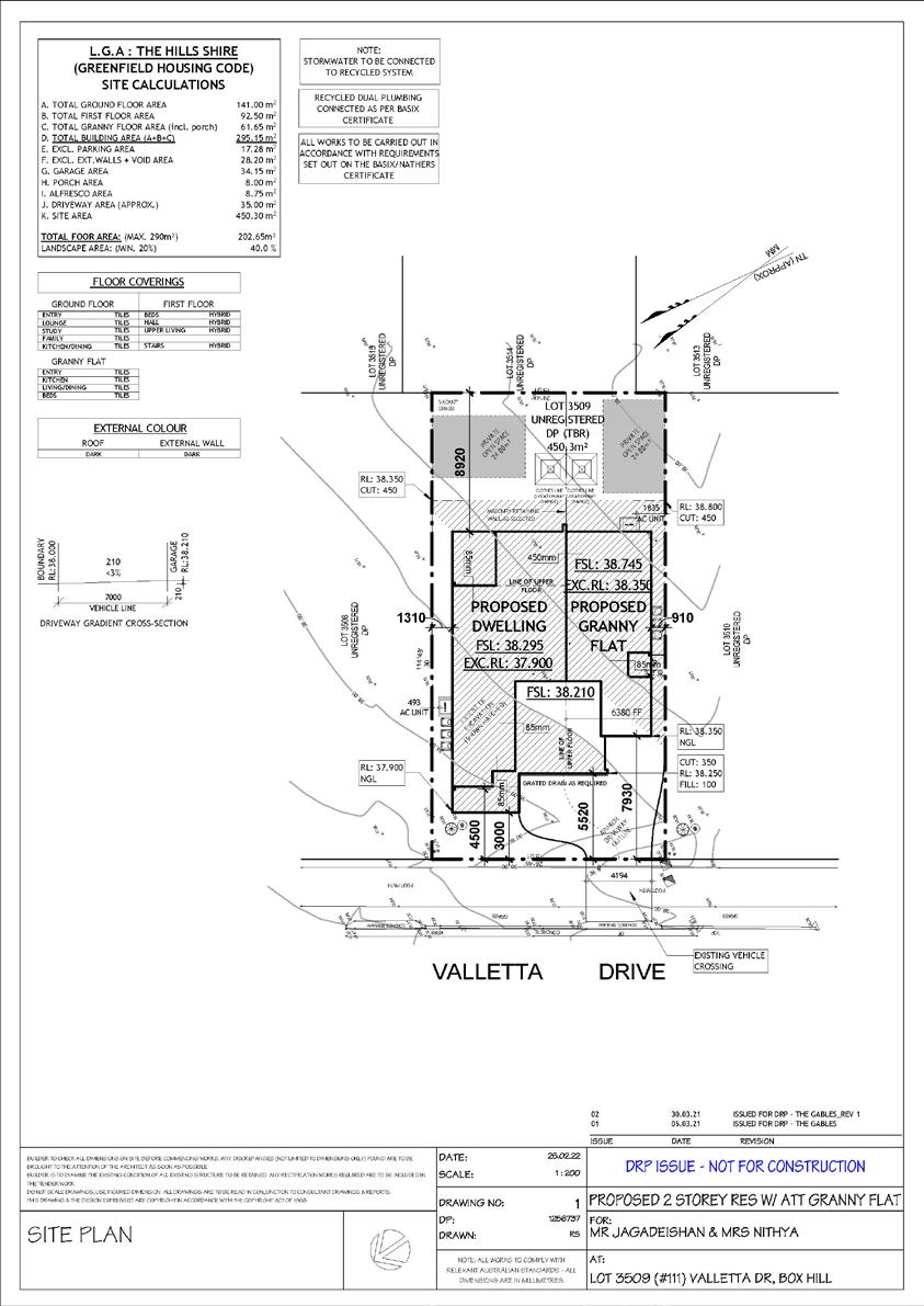
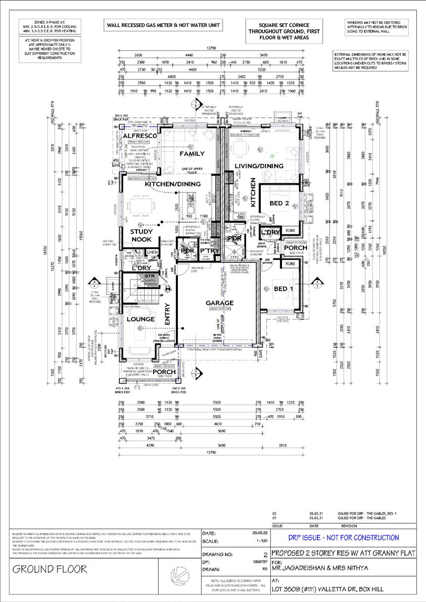
1
1
PROJECT
PROJECT
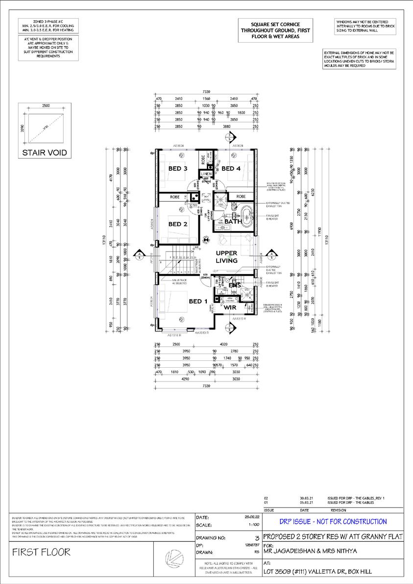
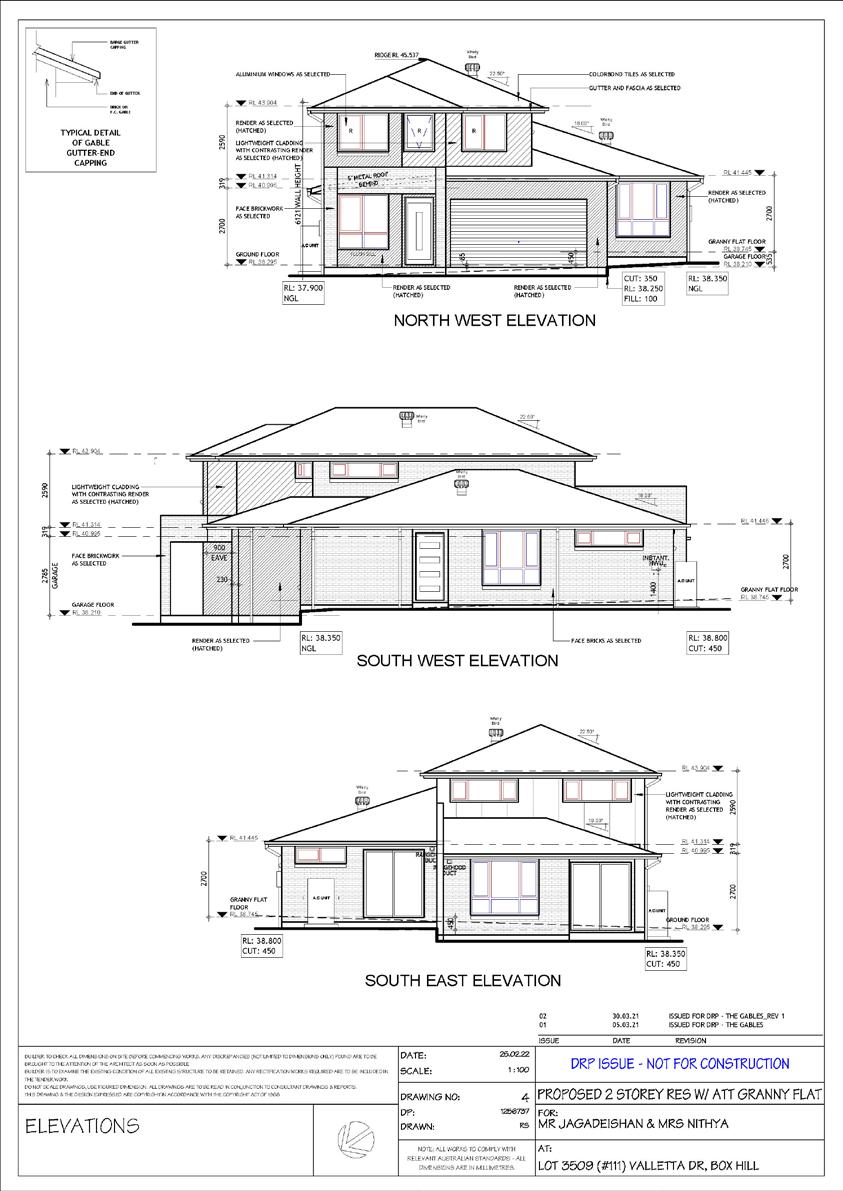
1
1
PROJECT
PROJECT
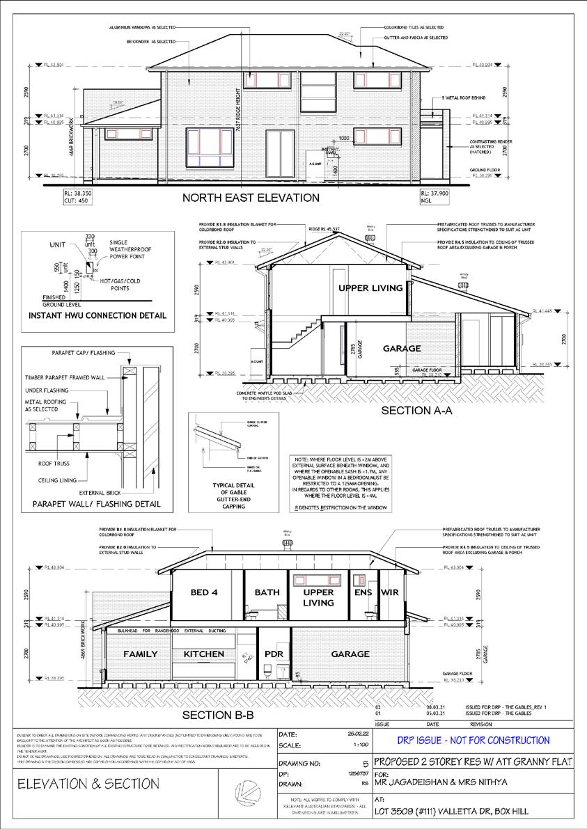
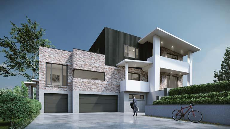
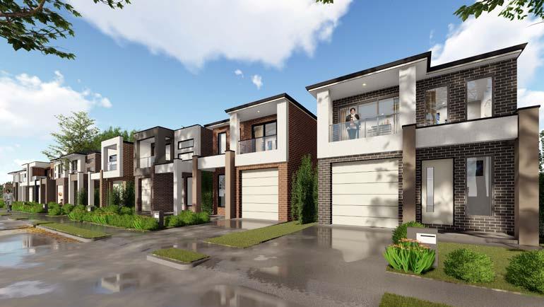
OF 3D VISUALIZATION
SAMPLES
PROJECT 1
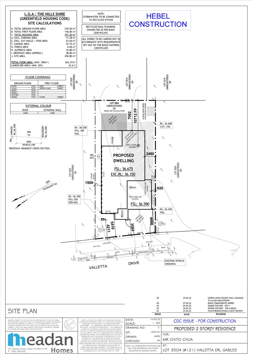
2
2
PROJECT
PROJECT
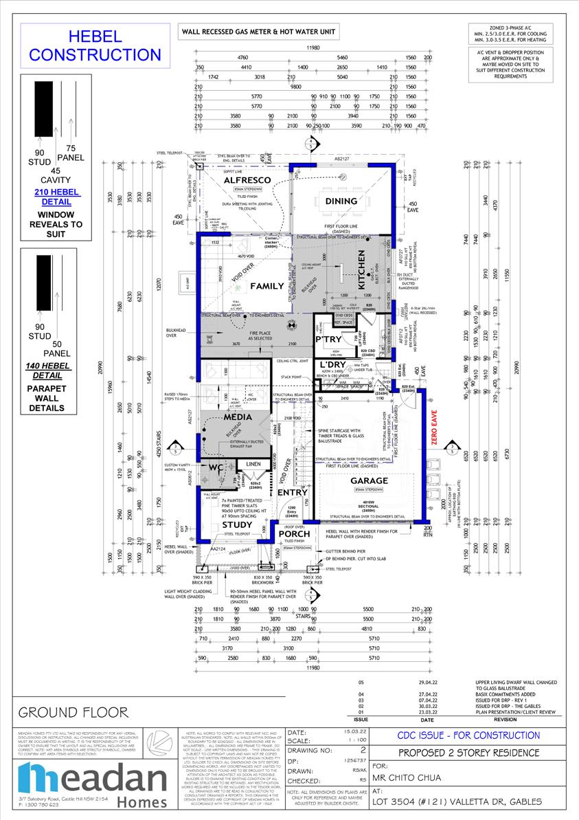
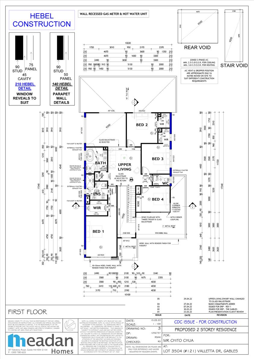
2
2
PROJECT
PROJECT
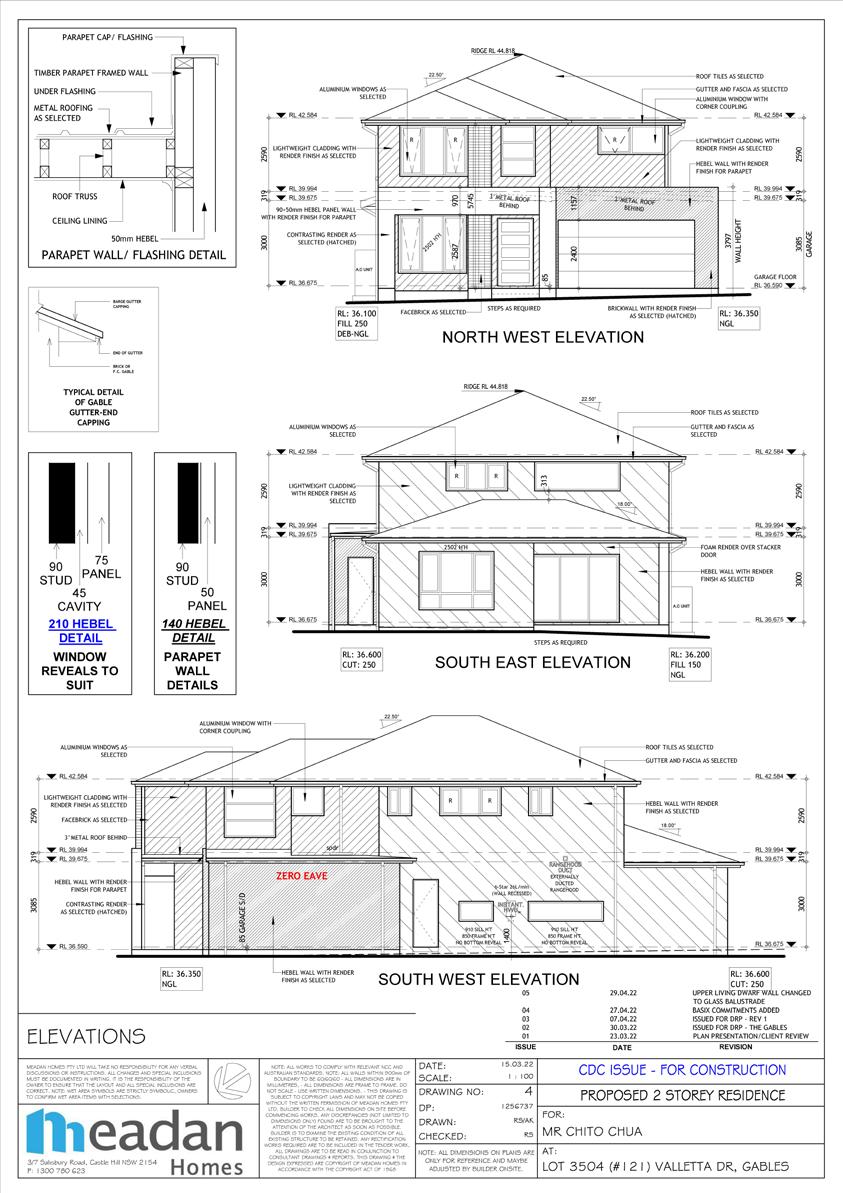

2
2
PROJECT
PROJECT
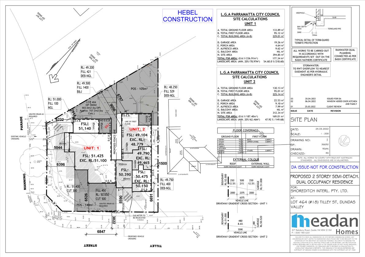
3
PROJECT
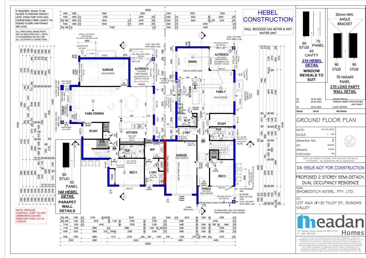
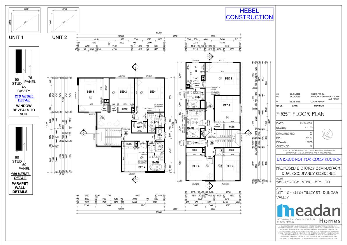
3
PROJECT
3
PROJECT
