3 minute read
GALLOWAY’S FURNITURE SHOWROOM VICTOR LUNDY-


CLIENT:
REQUEST:
Advertisement
BUILT BY:
Create a Physical Model of Victor Lundy’s Galloway’s Furniture Showroom, for Display
Architecture Sarasota Kyle Fernety
OVERSEEN BY: Christopher Domin
Project Info
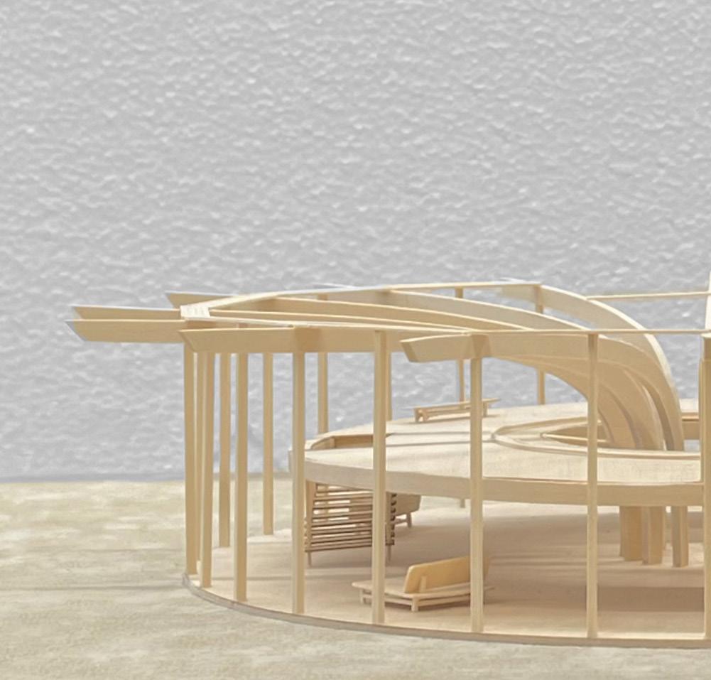
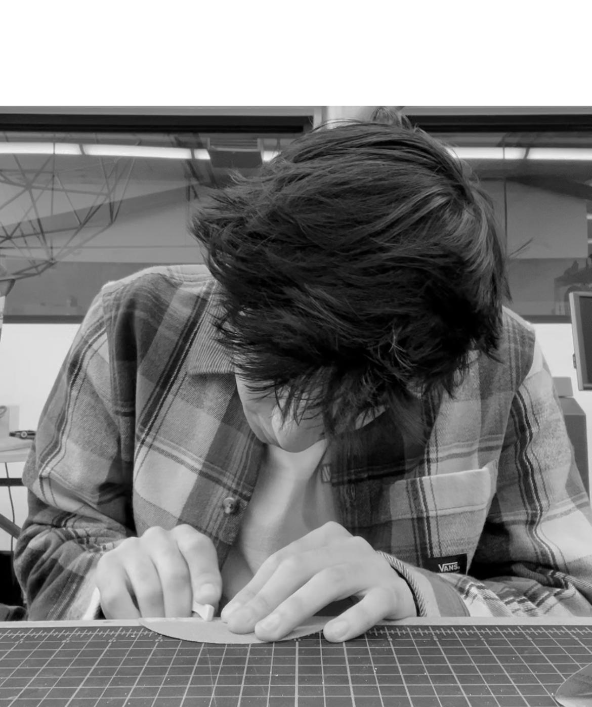
During the Fall 2022 semester, I was approached by my professor of Integrated Technologies to work under his supervision on a paid project over the Winter break. My task was to help create a professional physical model of Victor Lundy’s Galloway’s Furniture Showroom to be displayed in an exhibit for Architecture Sarasota’s museum located in Florida. Over the course of the break, I developed my physical modeling and digital drawing skills. In creating this model, I utilized laser cut machines, 3D printers, band saws, and sanding machines.
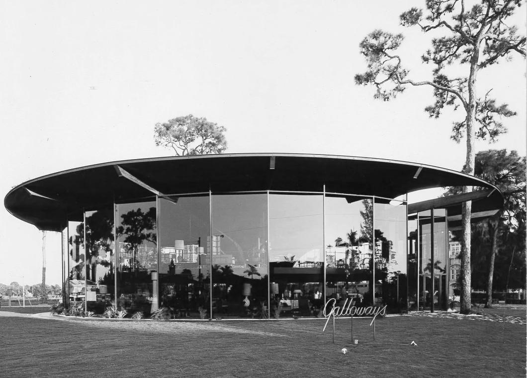
GALLOWAY’S FURNITURE SHOWROOM
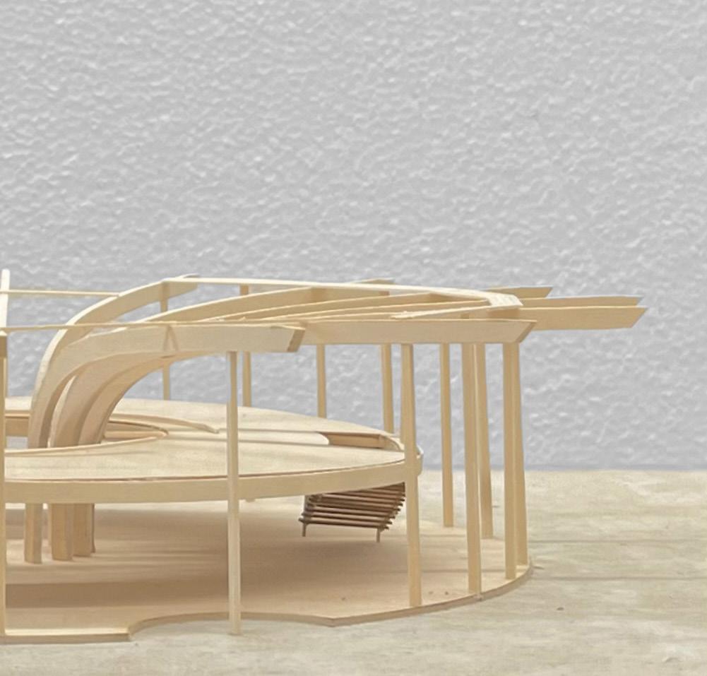
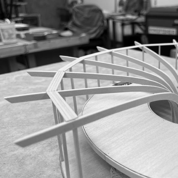
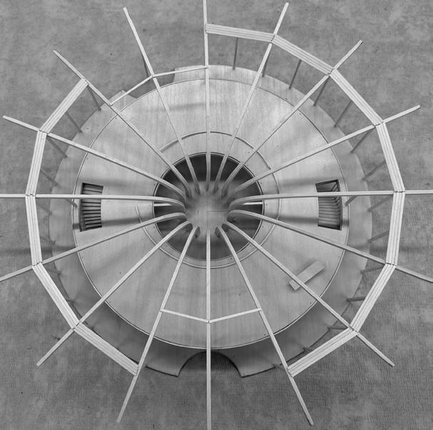
Victor Lundy’s Galloway’s Showroom was an exquisite display of innovative design from the late 1950s. The design was based on Lundy’s love of nature and organic forms. This can be seen in roof cutouts that allowed for the growth of trees. Seen above are the massive glulam beams that span across in 16 directions from the center point of the showroom. Utilizing the beams, Lundy hung a mezzanine to create an illusion that the second floor is floating. He followed this up by including two floating staircases that hung from the floating mezzanine.

Glulam Beams
In total, there are 16 glulam beam that branch out from the center of the showroom. To create the glulam beams:
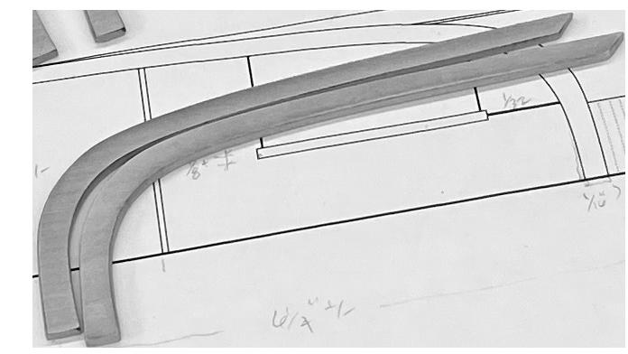
1) Accurate digital drawing to serve as basis for the laser cut file
2) Setting up laser file and properly adjusted the settings for the cut
3) Once cut, I hand-sanded the burnt edges off for a smooth finish
Connecting Displaced Information
Proper files of the project were not completely available. When this building was remodeled in 1970 by VisionWorks, much of the original information was displaced or thrown away. In order to create an accurate physical model, I needed proper dimensions and scale. Through acquiring old VisionWork plans and the few Victor Lundy plans still available, I pieced together information and was able to fill in the missing spaces.
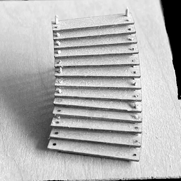
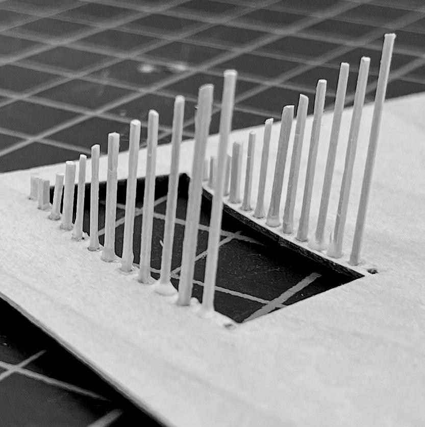
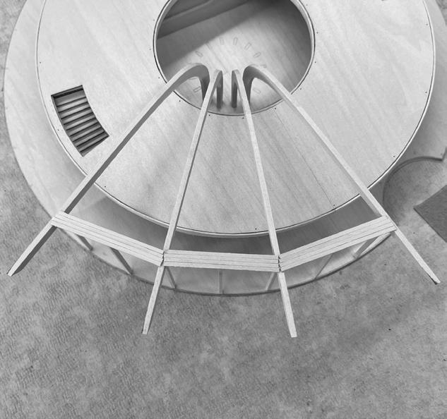
Creating The Floating Stair


Creating the floating stair took many trials-and-errors to get right. The photo above shows my final test copy where I found the right method of assembly. Through experimentation of piano wire and other materials, we decided on basswood to serve as the metal rods. The basswood added light and warmth and allowed for a perfect pressure fit between rod and stair tread.
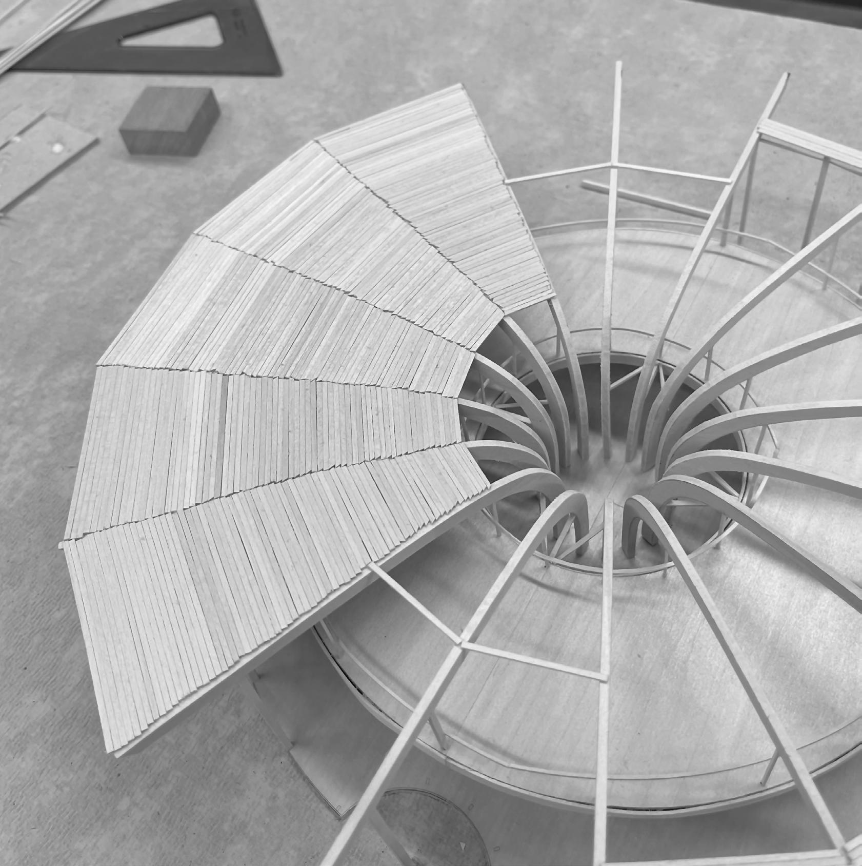
Adding Roof Detail
Victor Lundy used a T&G ceiling design. T&G meaning a tongue and groove tray ceiling. To create an accurate portrayal, I hand-cut custom pieces of basswood strips and individually placed them across the glulam beams.
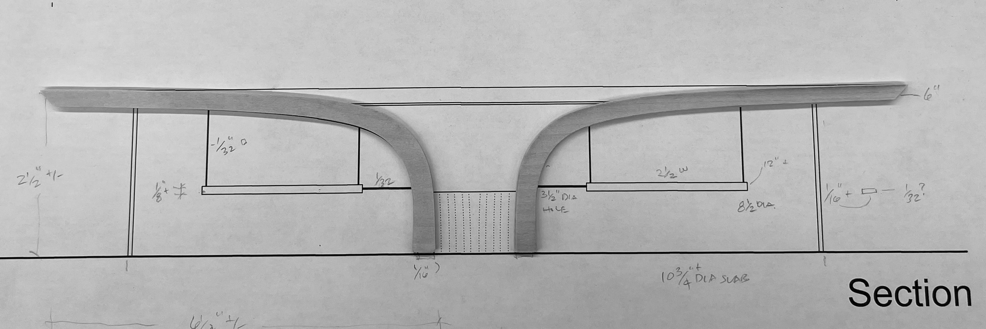
Creating Working Files
For this project, I created accurate floor plans and section plans in order to aid the physical modeling process. Once the plans were digitally drawn in Rhino, I took them to illustrator where I added proper line weighting.
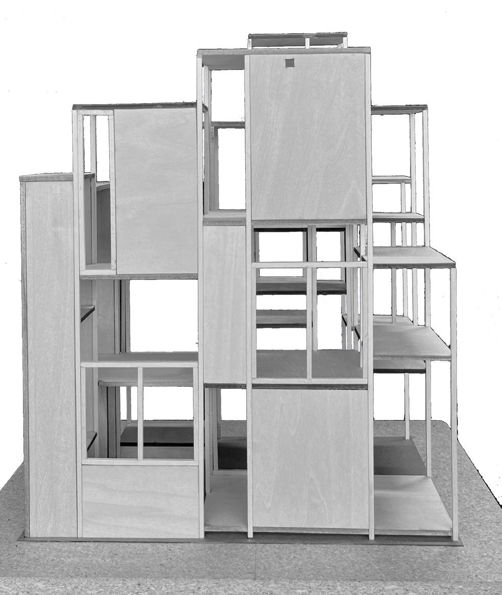
PRECEDENT STUDY - HOUSE NA
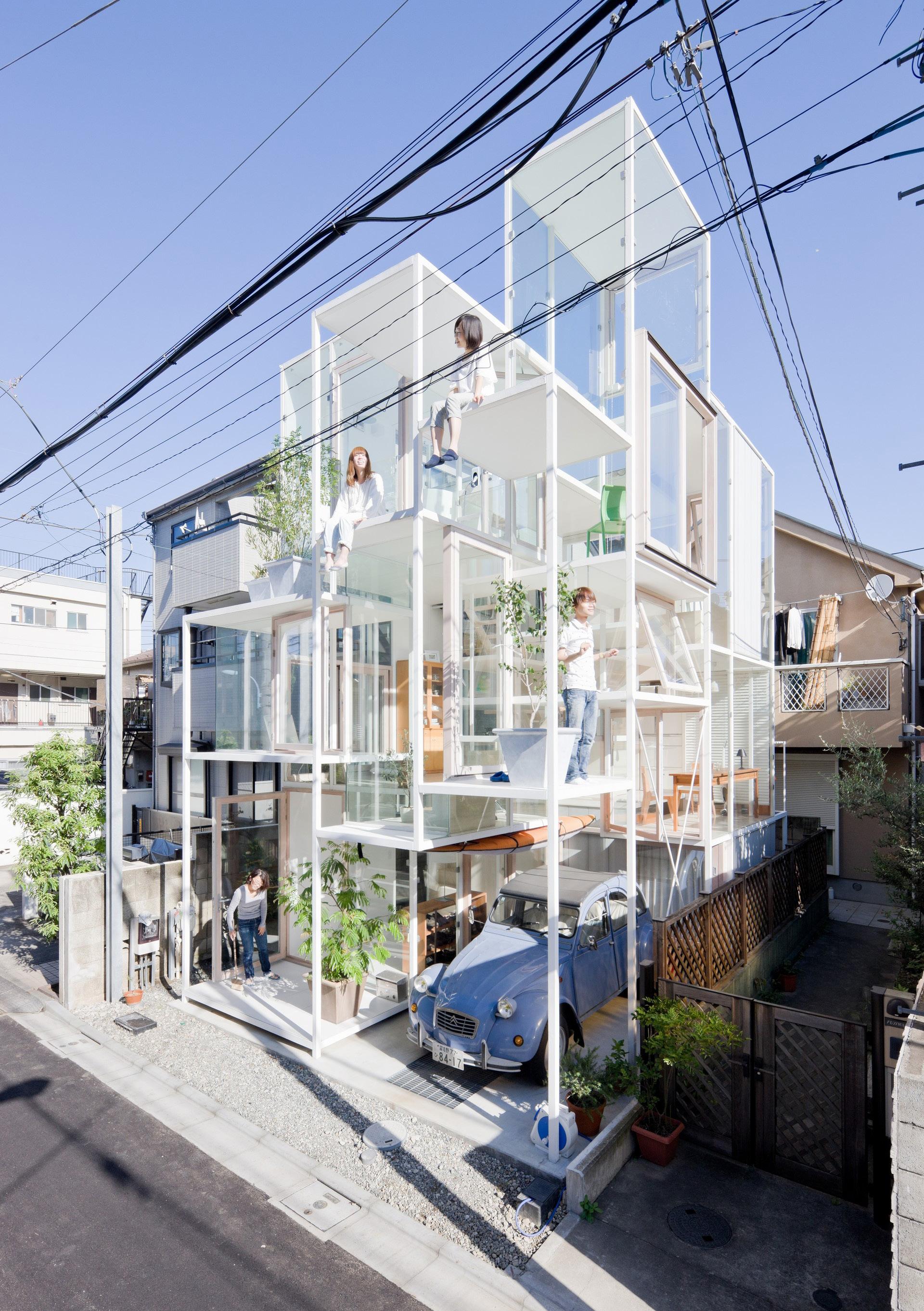
“To dwell in a house, amongst the dense urbanity of small houses and structures can be associated to living within a tree.”
Project Info
House NA is not your typical residential house. Designed by the Japanese architect Sou Fujimoto, it was completed in 2011. House NA serves as a striking example of Fujimoto’s signature style, which combines modernist and minimalist design principles with a unique approach to spatial design.
Inside the house, Fujimoto has created a series of interconnected spaces that flow seamlessly from one to another. There are no traditional walls or doors, and the house is instead divided into a series of platforms and levels that are connected by stairs and ramps. This approach creates a sense of fluidity and allows the residents to move through the house in a continuous loop.
ARCHITECT
Sou Fujimoto
PROJECT DATE
2011
LOCATION
Koenji, Tokyo, Japan
= More Frequent Paths
= Less Frequent Paths
Circulation
Utilization of both fixed and movable stairs to better help serve its unique circulatory path.

This helps facilitate irregular movement to serve their clients unique want of having a nomadic sense of living.
SE View Summer Solstice 12:30 PM
Solar

The large floor-to-ceiling windows on the House NA’s transparent facade face south, allowing for maximum exposure to sunlight during the winter months when the sun is lower in the sky. While in the summertime it allows for less light to enter in.

Ventilation
Glass Clamp
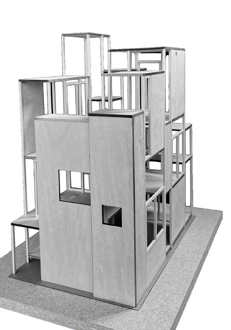
VARIETY:

USE: Square Creates tight connection between glazing and steel frame
CONCRETE: CONCRETE PANELS
USE(S):
Provide Stability & Resist Lateral Loads
LOCATION: Side Elevations (East & West)
WOOD: WHITE TINTED BIRCH
USE(S):
- Wood-Frame Fenestrations
- Serves as a Visual Transition with Structure
LOCATION:
- All Throughout Exterior Build
- Interior Flooring
GLAZING: SEE-THROUGH GLASS
USE(S):
Visual Connection & Solar Allowance
LOCATION: All Elevations
STEEL: WHITE PAINTED STEEL
USE:
- Steel Frame Bracing
- Welded On-Site
- Used for Slender Design
- Less Cumbersome than Wood
LOCATION: All Elevations
SEPARATION & COHERENCE

House NA is designed to encourage interaction and socialization between its occupants. Likewise, it can also provide spaces of intimacy if two individuals choose to be close, while also accommodating for a group of guests by distributing people across the house.
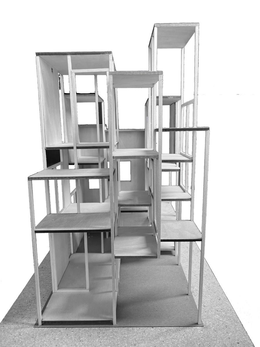


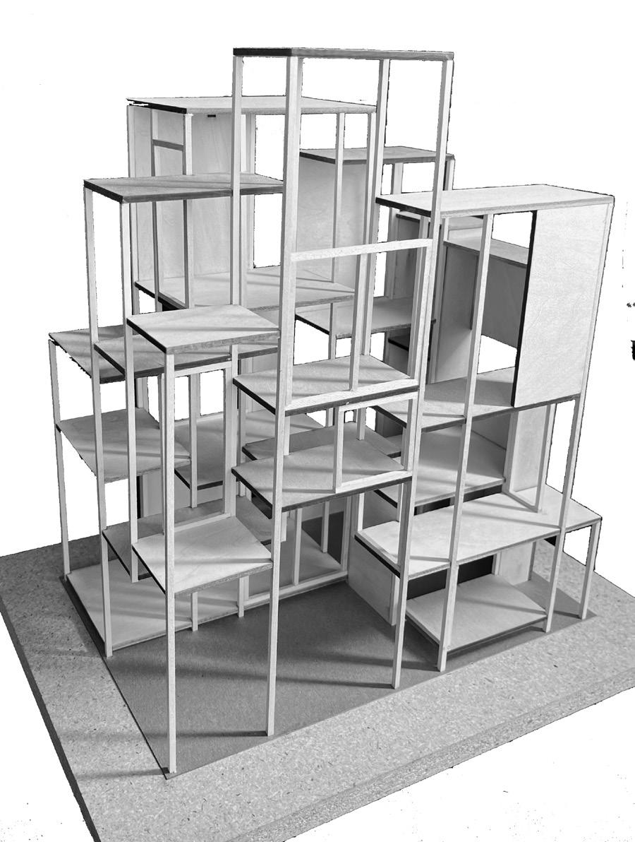
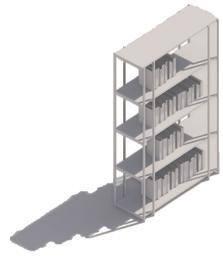
Column Grids
Due to the complex design of House NA, I created a column grid to aid in my analysis of the structural system. Through usage of a digital model created, I was able to better understand the spacing of the column grid and the support for the 21 individual floor plates.
