Applied Thermal Control MG-Series User & Operation Manual
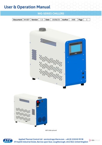
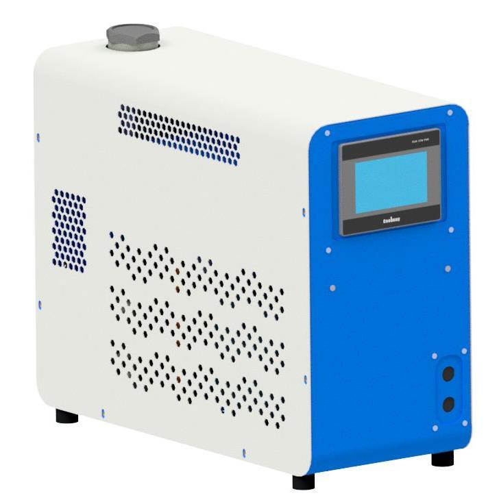
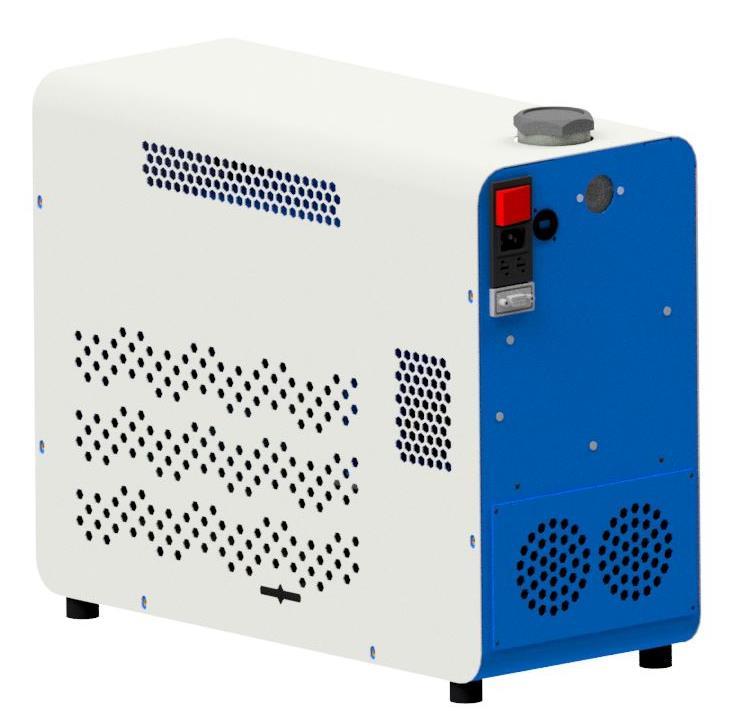
MGT chiller pictured
1.0 INTRODUCTION
By selecting an ATC product, you have invested in many years of experience in the design and manufacture of precision temperature control instrumentation.
ATC has built your unit without compromise to meet the objectives of performance and reliability. Please read this manual carefully to ensure you understand the operation of the machine and how to use the unit safely and efficiently.
CAUTION
Please read this User & Operation Manual in full. For maintenance tasks beyond that of routine cleaning, please consult the separate Maintenance Manual. This contains further information and schematics for the use of suitably qualified personnel.
Contact information
If you have any questions regarding installation or repair of this unit, please contact ATC direct.
Applied Thermal Control Ltd.
39 Hayhill Industrial Estate, Barrow Upon Soar Leicestershire, LE12 8LD United Kingdom
Tel: +44 (0) 1530 839998
E-mail: support@app-therm.com
2.0 IMPORTANT INFORMATION
2.1 INTENDED USE
Applied Thermal Control products have been designed to control the temperature of specific fluids. The units feature inlet and outlet connections for the temperature control of external systems (process fluid circuit).
Applied Thermal Control products are not suitable for direct temperature control of foods, pharmaceutical or medical products. This is defined as unprotected contact of the object with the process fluid used by the chiller.
The product must be used in line with the instructions contained within this manual. A separate maintenance manual is also available. Particular attention should be given to the safety notices prior to installing and operating the machine.
This appliance is not intended for use by persons with reduced physical, sensory or mental capabilities, or lack of experience and knowledge, unless they have been given supervision or instruction concerning use of the appliance by a person responsible for their safety.
2.2 SAFETY NOTICES
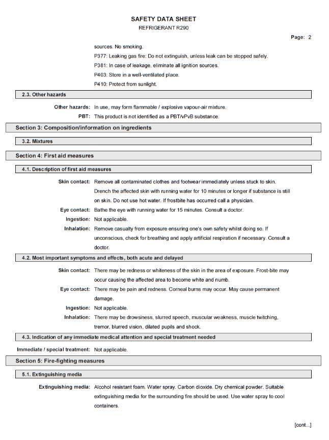
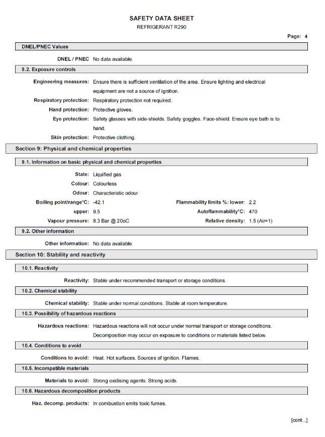
R290 refrigerant is an environmentally friendly alternative to HFC refrigerants. However, it is classified as a highly flammable gas. At the same temperature and pressure, R290 is heavier than air and usually reaches higher concentrations near the ground. R290 is odourless, but can be easily detected with commercially available gas detectors and leak detection devices.
Additional information regarding R290 refrigerant can be found in section 10.1 R290 . The refrigerant type and charge is always labelled on the unit.
For your safety, we draw your attention to the following WARNING and CAUTION marks throughout the manual. Warning symbols can be found on the unit. Ensure you have read through all warnings before starting the unit.
The safe operation of ATC products always remains the responsibility of the operator. This equipment is intended to be used as a liquid temperature conditioning device – it requires no external pump, nor any further manipulation of temperature. If the equipment is used in a manner not specified by the manufacturer, the protection provided by the equipment may be impaired. Failure to comply with a ‘WARNING’ may result in personal injury or death. ATC does not accept any liability for injury caused through misuse of this equipment.
REFRIGERANT: R290
For your safety, we draw your attention to the following warning and caution marks throughout the manual Identified by the following symbols. Where relevant, these are also labelled on the machine. All warnings and cautions should be read prior to starting the machine.
Warnings denote a hazard that MAY cause serious personal injury or death.
CAUTION
Cautions denote a hazard that MAY cause minor personal injury or damage/failure of the product or facility.
The safe operation of ATC products remains the responsibility of the operator at all times. This equipment is intended to be used as a liquid temperature conditioning device – it requires no external pump, nor any further manipulation of temperature. If the equipment is used in a manner not specified by the manufacturer, the protection provided by the equipment may be impaired. Failure to comply with a ‘warning’ may result in personal injury or death.
ATC does not accept any liability for injury or damage caused through misuse of this equipment.
MG-SERIES CHILLERS
• This appliance should only be installed by persons who are appropriately trained, skilled and competent to carry out the work properly and safely. Servicing and repair is to be undertaken by qualified engineers for the handling of hydrocarbon refrigerants
• Do not store explosive substances such as aerosol cans with a flammable propellant within or close to this appliance.
• Do not damage the refrigerating circuit
• Do not use electrical appliances inside the enclosure of this appliance unless they are of the type recommended by the manufacturer
• To be installed in accordance with the Safety Standard for Refrigeration Systems, ANSI/ASHRAE 15 or local equivalent.
• Adequate ventilation of clean, cool and dry air is required for all air-cooled chiller appliances during normal operation and allows the chiller to operate at maximum capacity.
• If the appliance is placed in a location with floor void(s) below (such as false floors, drains or cable pathways etc.), precautions must be made to either seal the void(s) or supply adequate low-level ventilation. In particular, precautions should be made against refrigerant collecting in drains.
• If the appliance is placed in a machinery room with the increased risk of sources of ignition, it is advised that a refrigerant leak detector and a mechanical low-level ventilation system exhausting to an external atmospheric safe area is installed.
• Ensure all operatives are aware the appliance contains a flammable, odourless refrigerant.
• The ventilation system should be configured to be automatically activated upon detection of a refrigerant leak or set to continuously operate.
• Keep ventilation openings of the appliance enclosure or the structure of
• built in equipment clear of obstruction.
MG-SERIES CHILLERS
• Always ensure appropriate fire extinguishers are placed at entrances and exits to the room housing the appliance(s) and adequate warning signage is installed to local laws/site requirements.
• Locate all refrigerant containing machinery so that damage from external sources would be highly unlikely
• Should a suspected leak become apparent, immediately evacuate the area and remotely switch off the appliance if safe to do so.
• If a leak is suspected DO NOT disconnect the plug from the main supply socket or from the appliance inlet as this could act as a source of ignition. Leaking refrigerant may ignite and cause injuries.
• The appliance must be disconnected from its power source during cleaning; when maintenance and the replacement of parts is required, the equipment must be safely disconnected and isolated from the power supply using a lockout system at the isolation device.
• It is advised that the electrical supply to the equipment is protected by an appropriately selected Residual Current Device (RCD).
• If the supply cord is damaged, it must be replaced by a service engineer or other qualified person.
• Fixed wiring appliances (those not supplied with a plug) shall incorporate a switch disconnector to meet the specification of IEC 60947; this is to be installed within the fixed wiring installation in accordance to the local wiring rules / regulations to provide all pole disconnection of the power supply.
• Do not substitute the current refrigerant for any other refrigerant. The refrigerant used will be labelled on the appliance.
• Water pressures of up to 10 Bar during operation
• Hot and cold surfaces are present during operation.
• Always ensure the unit is isolated before service. The product is protected from overcurrent by fuses and MCBs. Never bypass these components.
• During fault diagnostics and maintenance, it may be necessary to remove panels, which expose the operator to the dangers of pressurized systems, hot or cold pipes and electrical circuits. Only qualified personnel who are aware and equipped to deal with these systems should carry out such work.
• Under no circumstances leave the product unattended with any panels/covers removed
• Any temporary electrical supply to the chiller should be correctly earthed and connected through an earth leakage trip.
• Never alter settings of pressure switches, overloads, circuit breakers or any safety device without first consulting Applied Thermal Control.
CAUTION
• Always wear appropriate PPE when performing routine maintenance. It is advised that suitable gloves and eye protection are used as a minimum requirement.
• Process fluid circuits connected to the appliance are designed to safely release/bypass abnormal pressure. There will be no possibility for the release of flammable refrigerant in this scenario.
• The pressure relief valve is factory-set and there is no provision for adjustment by the end-user
• Marking and signage to the equipment must continue to be visible and legible. Marking and signs that are illegible shall be corrected.
• The appliance is to be located in a position where it is not likely to be exposed to any substance that may corrode refrigerant containing components, unless the manufacturer has explicitly supplied components are constructed of materials which are inherently resistant to being corroded, or are suitably protected against being so corroded.
2.WASTE DISPOSAL
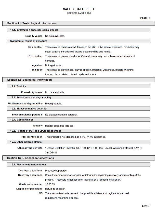
This product uses R290 refrigerant and compressor oil. Follow local regulations regarding the recovery and disposal of these substances. Refrigerant recovery must be completed by personnel qualified in the handling of hydrocarbon refrigerants.
Once oil and refrigerant are removed, the product must be handled as industrial waste in accordance with local regulations.
2.4 MODEL NUMBERING
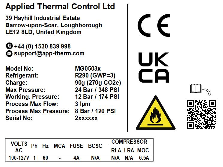
The model number of your ATC product can guide you to the sections of the manual specific to your model. The model number can be found on the serial plate of the product, similar to the below.
If the model number format shown below does not match the model number on the product serial plate, this manual may not be applicable to your product. Electronic copies of all standard product manuals are located on our website. If you have a non-standard product or require any further assistance with manuals, please contact us.
Control
Cooling capacity 5 500W
T Touchscreen C Std temp controller R HGBP only Pump size 03 3lpm
MG _ 503 _
Electrical spec
1 (115Vac, 1~, 60Hz)
5 (220-240Vac, 1~/2~, 50/60Hz)
2.5 UNPACKING UNITS
Please check that both the packaging and the unit are undamaged. If there is any doubt, it is vital that you inform both ATC and the carrier. There are no hidden shipping bolts or other fixings. You should inspect the packaging for signs of transit damage before signing for the unit, and if possible, unpack the unit before signing. Once you have signed for the goods, ATC cannot be held responsible for any transit damage subsequently found.
This mass of this unit is within manual handling limits of a two-person lift. Safe manual handling practices must be adhered to.
Remove the unit from its original packaging and ensure that there is no packaging left around the cooling ducts. There is no internal product packaging that requires the chiller to be opened.
Please retain all packaging in the unlikely event that the chiller needs to be returned to our local representatives.
2.6 SITE REQUIREMENTS
1 Storage temperature range. Without process fluids, -20°C to +70°C.
2 Storage humidity range. Non-condensing, relative humidity 5% to 95%. Before starting product, allow product to acclimate for 24h in location of use when storing outside operating humidity range.
3 Operating temperature range. With appropriate process fluids,
MG-SERIES CHILLERS
Standard Unit: +4°C to +35°C
Extended: -10°C to +55°C
4 Operating humidity range. 80% for ambient temperatures up to +31°C (+88°F), decreasing linearly to 50% relative humidity at +40°C (+104°F) ambient temperature.
5 Hard, level surface. A level surface is important for ensuring proper filling and allowing air to escape.
6 Electrical supply.
The Internal fusing for a standard unit is rated at 10 Amps. If options such as heaters are added, this may increase. The current draw for your specific unit will be confirmed on the serial plate of your unit.
For details on the required electrical supply, see production specification section 3.1 MG-SERIES (ALL STANDARD VARIANTS).
8 Clearance. Clearance is required to:
a) Provide unobstructed access to the electrical panel to use power switch in case of emergency.
b) Fit hoses and electrical supply to the rear of the unit allowing recommended bending radii.
c) Allow maintenance access points and side panels to be removed.
d) Allow process to take place – all models require the coolest, cleanest air that can be provided to achieve the best performance. This model draws air in from the left and right-hand sides (when viewing from the front of the unit) and rejects heated air to the rear.
e) 0.5m clearance is recommended on air-on and air-off sides. Do not cover any vents.
9 Plumbing. Tubing, piping or hose must be clean and compatible with the fluid to be used. The product is compatible with water-glycol mixtures such as Hexid A4 and A6. Ensure the connected pipework is suitable for handling the nominal flowrate at system pressure of around 2 bar.
10 Indoor use only. Altitude up to 2000m above sea level. Ensure the unit has adequate ventilation. It is suggested the unit is located on a suitable workbench to provide an ergonomic working height.
CAUTION
• Always use ATC recommended fluids in our products – many sealing compounds and materials are present and unapproved fluids have the potential to corrode your application and damage seals.
• Do not use inadequately rated wiring. Consult an electrician if you are unsure.
• The safety of any system incorporating the equipment is the responsibility of the assembler of the system
• Do not replace detachable mains cords with inadequately rated cords. Contact ATC for appropriately rated products.
MG-SERIES CHILLERS
2.7 WARRANTY REGISTRATION
Please visit the website warranty registration page to ensure ATC can offer you the best possible support.
https://www.app-therm.com/warranty-registration/
a) I’m experiencing problems with my chiller. It’s within warranty – what do I do next?
Contact ATC to discuss the issue you are having on +44(0)1530 839998 or support@app-therm.com. Be sure to have your model number and serial number on-hand to aid those attempting to solve remotely.
b) Telephone support couldn’t fix my chiller – what do I do next?
An RMA form must be completed. This allows both the end-user and ATC to clarify your details, to set the party responsible for shipping costs, and to set a different return address if desired. Shipping advice is provided, and the end-user must sign a declaration that states the unit is safe to handle. Return the form by email for fastest response.
c) What happens if my chiller failed outside warranty or requires non-warranty repair work?
A purchase order will be requested to cover an initial inspection – this will only be invoiced if the inspection shows there is no fault. If packaging is required, i.e. a crate, a separate charge will be levied. If the end user prefers ATC to arrange a collection, a shipping charge may be levied.
d) Our process must continue running – can we have a loan unit whilst our chiller is in repair? ATC hold several standard air-cooled chillers at the factory for the sole purpose of offering for loan. These are available on a first come, first-serve basis. Models up-to 3kW capacity are available.
3.0 PRODUCT SPECIFICATIONS
3.1 MG-SERIES (ALL STANDARD VARIANTS)
Weight 30Kg
Form factor Bench mounting recommended
Dimensions
W220 x D516 x H428mm
W8.66 x D20 32 x H16.85”
Noise level 65dB(A)@1m
Toolless access No
Technology Vapour compression
Cooling capacity
(Ambient temperature at +20°C)
0.5 kW
1,706 BTU/h
0.142 TR
Refrigerant R290
Refrigerant charge 90g
Ambient temperature range (operating) 0°C to +35°C
Maximum ambient (transport/storage) 70°C
Control method
MGT & MGC models: PID via solenoid valve
MGR models: HGBP only
Stability ±0.1°C @ 500W Load
Resolution 0.1°C
Sensor type
MGT & MGC models: PT100
MGR models: None
System volume 0.7L
Pump
(As per model number configuration) 24V brushless centrifugal, 3L/m
Warranty options 2-year parts, 1-year labor Enhanced on request
Rated duty cycle S1 Continuous
4.0 QUICK START GUIDE
1 Remove all the packaging (Section 1.3)
2 Connect chiller’s outlet and inlet process to your application
3 Fill up the chiller with appropriate coolant
4 Use the name plate on the back of the chiller to verify the appropriate voltage and supply the power using provided cables.
5 Turn the power switch ON
6 Slowly add more coolant as process lines fill and the coolant is circulated around the process system.
7 Using the controller, set the desired temperature.
5.0 INSTALLATION
5.1 HOSE RECOMMENDATIONS
Having ensured that your installation meets all site requirements, it is best practice that the fluid lines between your application and the chiller have the following characteristics.
1 Short in length – this reduces friction-based pressure drop and addition ambient heat load.
2 Large diameter bore – at least 9.5mm (3/8”).
3 Free from 90° bends – to limit the effects of water hammer. If this cannot be avoided, sharp changes of direction should be minimized so far as possible. Doing this correctly can yield higher pump performance and extend time between maintenance intervals. It will also reduce electrical energy consumption.
4 Clean – If your installation is to existing pipe work, it is good practice to flush the system with either a commercially available central heating cleaner or 5% acetic acid solution. The system should be flushed clean to remove all traces of cleaner prior to filling the system. Failing this, it is recommended to use a domestic bleach in 1:1000 solution with water
5 Opaque, ideally black – to inhibit light passing through the tube and algae building up. Alternatively, solid ABS or copper pipe can be used where application chemistry allows.
6 Insulation, where low temperature process is planned – the process line from chiller to application contains the feed of low temperature fluid. Insulation prevents heat from entering this line and can promote better stability. Uninsulated return lines are helpful where free cooling can be obtained by allowing heat to transfer to air – likewise, insulating the return line is helpful if the fluid temperature is below ambient.
CAUTION
Never use transparent tubing. UV light will pass through, prompting growth of organic contamination.
5.2 FLUID FITTINGS
1 Ensure the appropriate thread sealants are used in the fitting of adapters to hose. For metallic mating parts, we recommend Loctite 577. For plastic adaptors such as those supplied with the product, we recommend using ~8-12mm wide PTFE tape, wrapped around the male thread before tightening.
2 Ensure that the system is correctly connected. The ‘donut’ labels around the ports are clearly marked with inlet and outlet symbols and function in both English and French language. Ports marked as outlet means fluid leaves the product and must be connected to the process inlet.
3 Check all joints are tight and leak free.
4 Where this product is incorporated into other equipment, it is the responsibility of the assembler to ensure safety
5.3 BACKFILLING
CAUTION
• In situations where the chiller is situated physically lower than the application being cooled, fluid will apply pressure to the water circuit of the product.
• The weakest seal is normally the tank lid, and this is typically where fluid will escape the unit.
• Ideally, the product will be located higher or level with the product waterline. If this is not possible, a non-return solenoid valve kit can be installed as an optional standard assembly.
• Please raise any questions with the sales team on sales@app-therm.com.
5.4 VOLTAGE SELECTION
CAUTION
• Different chillers will have different requirement for electrical supply. The specification and requirement can be found on the back plate of the chiller.
• Please ensure that the voltage supply and number of phases are correct on the site and your power supply can handle the stated current draw.
• Where key-switch voltage selectors are fitted, check these have been correctly set to match your electrical supply.
MG-SERIES CHILLERS
5.5 FILLING PROCEDURE
a) Check all application valves are open, including solenoid valves and variable position valves.
i) The product will require an open water circuit to pump into.
ii) Any obstructions can increase the time, or entirely prevent the bleeding of air from the system.
b) Remove the cap from the tank lid on the top of the product.
i) Fill the tank until fluid is visible at the centre of the tank sight glass. This is the maximum fill level.
c) Switch the unit on
i) Check power is connected and switched on.
ii) Switch the unit on at the rocker switch. The pump will start running immediately.
iii) Keep the unit running until the water level in the tank drops and cuts out on the level switch interlock.
iv) Turn the unit off at the main switch.
v) Fill the tank again to lift the level switch.
vi) Start the product
CAUTION
CAUTION: Do not run the pump dry.
d) Repeat step (c) until the chiller does not cut out on the level switch.
e) Now with the unit running:
i) Leave the cap off the tank for 20-30mins to allow air to escape, or very loosely screwed on to prevent dust & debris ingress.
f) Check the application and tubing for signs of leaks whilst the chiller is running.
i) Replace the tank lid fully when satisfied the system is full and bled of air and no abnormal sound can be heard from the pump
5.6 DRAINING A SYSTEM
a) Isolate the unit. Have a suitable receptacle or drain on-hand.
i) Remove the tank lid to allow air into the system.
ii) Disconnect hoses individually. Be aware hoses as well as the unit are filled with fluid.
iii) Use tank drain tap (where fitted).
iv) Consider using the red transport plugs to block product ports to give yourself time to empty hoses before continuing to empty the product.
b) Local rules affect where fluid can be disposed of.
Ensure hazardous products do not enter the water course and are reclaimed from the unit for professional disposal
6.0 CONTROLLER OPERATION
Controllers are fitted to all MGT & MGC models. MGR models provide a fixed cooling output, and as such do not have a controller, MGR models can be fitted with an optional temperature display. EMG models are adjusted at the hot-gas bypass only, for more information refer to the Maintenance manual.
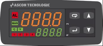
6.1 KR1 CONTROLLER – MGC MODELS
The KR1 is a high performance PID controller, which can control temperature to within 0.1˚C of set point. In addition, there is a high and low temperature WARNING via the LED on the display of the controller, which is triggered if the temperature deviates more than 10̊˚C from the set point.
DISPLAY CONTENTS DURING NORMAL OPERATION
1 Menu navigation button: Return 2 Menu navigation button: Up
3 Menu navigation button: Down
4 Menu navigation button: Enter
5 Setpoint value (SP) display, set by user.
6 Active output (1-4) display
7 °C or °F temperature unit display, settable in the ‘inP’ group.
9 Alarm active display. This appears when output is beyond the set alarm point.
10 Present value (PV) display, from input sensor.
ACCESS TO SETTINGS
1 Press and hold for more than 5 seconds. The Present Value display [10] will show PASS while the Setpoint display [5] will show 0.
2 Using and buttons, set the programmed password – full access is granted by entering ‘40’. ATC are not responsible for damage either to the chiller or the connected equipment as a result of changing parameters without consulting ATC.
MG-SERIES CHILLERS
3 During parameter modification the instrument continues to perform process control. In certain conditions, when a configuration change can produce a significant change to the process, it is advisable to temporarily stop the controller from controlling during the programming procedure (control outputs [6] will be OFF).
A password equal to 2000 + the programmed value (i.e. 2000 + 40 = 2040). The control will restart automatically when the configuration procedure will be manually closed.
4 Press If the password is correct the display, will show the acronym of the first parameter group ‘inP’. Press and hold for more than 5 seconds, then the instrument will come back to the “standard display”.
5 The configuration parameters are collected in various groups. Every group defines all parameters related with a specific function (control, alarms, output functions).
6 Press and hold for more than 5 seconds, the instrument will come back to the “standard display”. For specific settings and guidance, review the controller datasheets provided by ATC. If you are not in receipt of these, please contact ATC using the information in the header of this document.
GENERAL NAVIGATION
A short press allows you to exit from the current parameter group and select a new parameter group. A long press allows you to close the configuration parameter procedure (the instrument will come back to the “standard display”).
When the upper display is showing a group and the lower display is blank, this key allows you to enter the selected group. When the upper display is showing a parameter and the lower display is showing its value, this key allows to store the selected value for the current parameter and access the next parameter within the same group.
Allows to increase the value of the selected parameter.
Allows to decrease the value of the selected parameter.
Pushing both and moves back to the previous group. Press and hold first, then also press and hold The selection of the group is cyclic (on a carousel), so it is possible to move back around to the group you require.
6.1.1 CHANGING SETPOINT
ACHIEVING DESIRED SET POINT
1 Push and hold until it shows “SP 1”
2 Use and to adjust the temperature setpoint
3 Press again to confirm the new temperature setpoint
4 The set value now will be activated, and the chiller will start
MG-SERIES CHILLERS
6.2 TOUCHSCREEN CONTROLLER – MGT MODELS
Annex E-17 Coolmay Mini Touchscreen
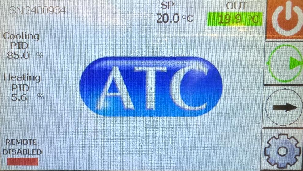
Splash Screen
Upon first powering on, the chiller will arrive at this page after a software loading sequence is complete.
1. Process start/stop (Start/stop fridge and water circuit).
2. Pump priming toggle button runs pump without process starting.
3. Next Page.
4. Access to settings menu. (See Passcode Entry)
5. Serial number is added by ATC during production.
6. Process outlet temperature. (Green = in range/Red = out of range).
7. Process Set Point.
8. PID Percentage outputs
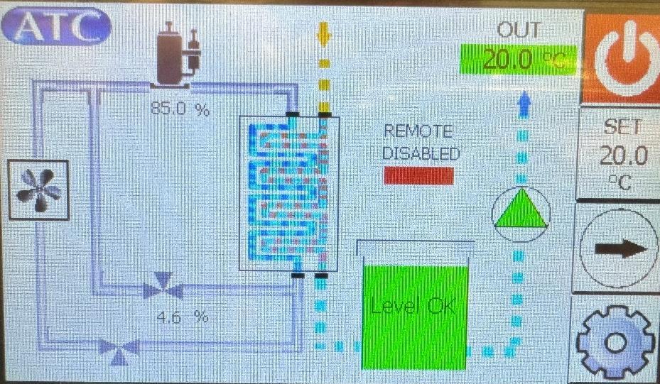
Process View
1. Process Start/Stop.
2. Set outlet temperature.
3. Next page.
4. Process outlet temperature. (Green = in range/Red = out of range).
5. Compressor utilization.
6. Tank level status. Green = Full
Amber = Top-up
Red = Low level (Chiller will automatically switch off to protect internal components)
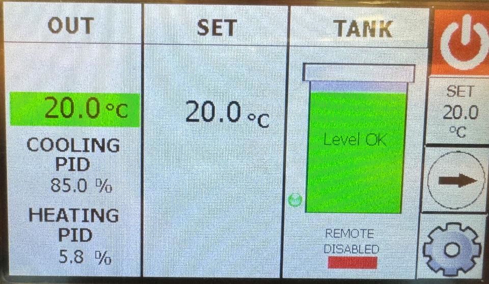
Simple View
1. Actual outlet temperature. (Green = in range/Red = out of range).
2. Setpoint temperature.
3. Tank level status.
6.3 REGULATING PRESSURE/FLOW
PRESSURE AND FLOW ADJUSTMENT IN MINI CHILLER WITH CENTRIFUGAL PUMP
The flow of the pump is dictated by the backpressure of the pipework. Reviewing the pump flow curve can indicate the expected flow. Centrifugal pumps have such a limited maximum pressure, that the water circuit components alone can hold the pressure, and no pressure relief valve is fitted. If further limitation of pressure is required, a flow control valve can be fitted to either the outlet or inlet of the chiller, depending on whether the application is to be pressurized or not.
7.0
BASIC TROUBLESHOOTING
# SYMPTOM CAUSES
1 Compressor or pump motor not running, control illuminated.
Level switch may have been tripped – Fill the tank up again to resolve the issue
High pressure switch may have been tripped:
a) Assess whether the ambient temperature is too high.
b) Assess whether ventilation/air circulation is poor.
c) Assess whether surrounding equipment is generating hot air and feeding it into the chiller air intakes.
If fitted, a low-pressure switch may have tripped – this indicates refrigerant loss. A multimeter is required to test this.
If running at a high setpoint, or if operating conditions have changed and raised the fluid temperature, it is possible the compressor has turned itself on high temperature internal protection.
Air-cooled models only:
Check fan spins freely and that condenser is clear of debris.
Water-cooled models only:
a) Check for sufficient flowrate and pressure of house water.
b) Assess whether the house water temperature is too high.
c) Assess whether any fouling of condenser plate heat exchanger has occurred.
d) Assess whether new equipment has been added to a shared water supply and contributed to either a lack of water flow (through flow splitting) or whether additional thermal load has been added to the central water’s chiller/cooler
2 Noisy Operation Pump motor or fan motor bearings may have failed. Pump head vane or seal may have failed.
3 High fluid pressure/low flow rate
4 Fluid collecting or leaking
In a 3-phase system, phase rotation may be incorrect.
Fluid lines may have become fouled through solid debris or biological growth.
a) Ensure biocides or pre-mixed biocidal process fluids are being used.
b) Ensure hoses are not transparent or translucent – UV light entering prompts growth.
General fluid leak can lead to flow rate failure.
Excess fittings, too many sharp direction changes, too small a diameter hose for flowrate or hoses too long at the wrong diameter.
Leaks are impossible to diagnose remotely, but usually you will see a pool of fluid on a lower surface. Do not confuse this with condensation from cold parts of the fridge.
Review the chemical compatibility of your fluid with the chiller. Contact ATC if you are unsure.
5 Poor Cooling Performance
Excess thermal load applied
a) Assess whether the ambient temperature is too high.
MG-SERIES CHILLERS
b) Assess whether ventilation/air circulation is poor.
c) Assess whether surrounding equipment is generating hot air and feeding it into the chiller air intakes.
Air-cooled models only:
d) Check if the fans are running.
e) Clean the condenser coil.
Water-cooled models only:
d) Assess whether house water temperature is too high.
e) Assess whether house water flowrate is too low.
Please contact ATC if you could not find the information you were looking for or still have an issue with the unit
MG-SERIES CHILLERS
8.0 END USER MAINTENANCE
Safely isolate your product prior to commencing any cleaning or maintenance tasks.
CAUTION
• Failure to carry out service at the specified intervals may permanently damage your equipment.
• Never blow out the condenser with compressed air (air-cooled units only).
• If the main lead is lost or damaged, contact ATC who will be able to supply a replacement to the correct specification.
• It is recommended that a full service and refrigerant circuit leak test of the appliance is conducted every 6 months by engineers qualified in the handling of hydrocarbon refrigerants.
Print this sheet out and display close to the chiller to maximize the visibility of maintenance requirements.
Weekly Week 1 Week 2 Week 3 Week 4
Check Fluid Level – Top up as required Monthly
Air-cooled only:
Check the condenser is free from dust or accumulation of debris
Drain process fluid and replace with fresh fluid
Check for fluid leaks throughout chiller and application
Clear any debris from inside the chiller
A vacuum cleaner is recommended for cleaning out the condenser (air cooled units only). Soft cloths and IPA are recommended for cleaning metallic surfaces. If any spillages have occurred, allow the water to evaporate and wipe up remaining glycol residue with a cloth.
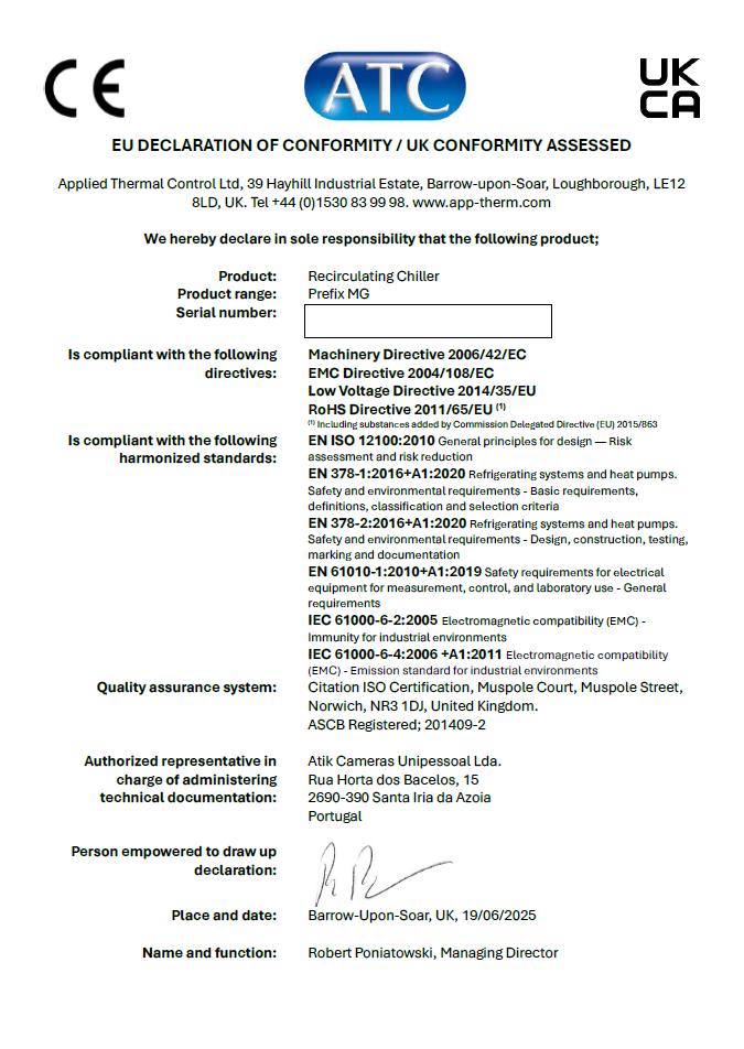
9.0 DECLARATION OF CONFORMITY
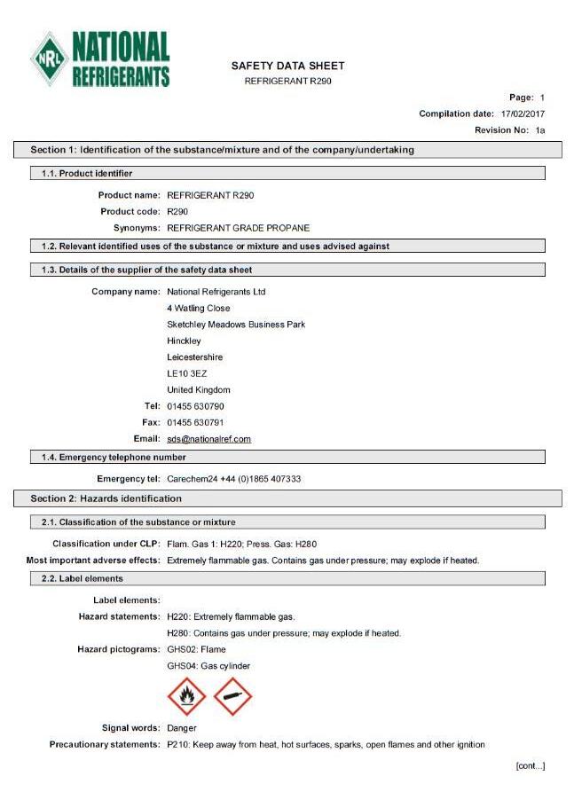
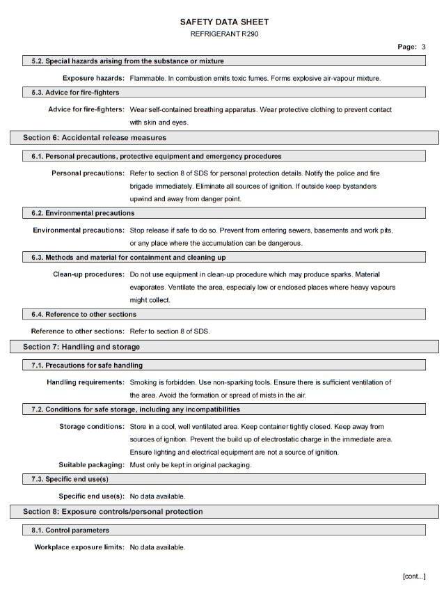
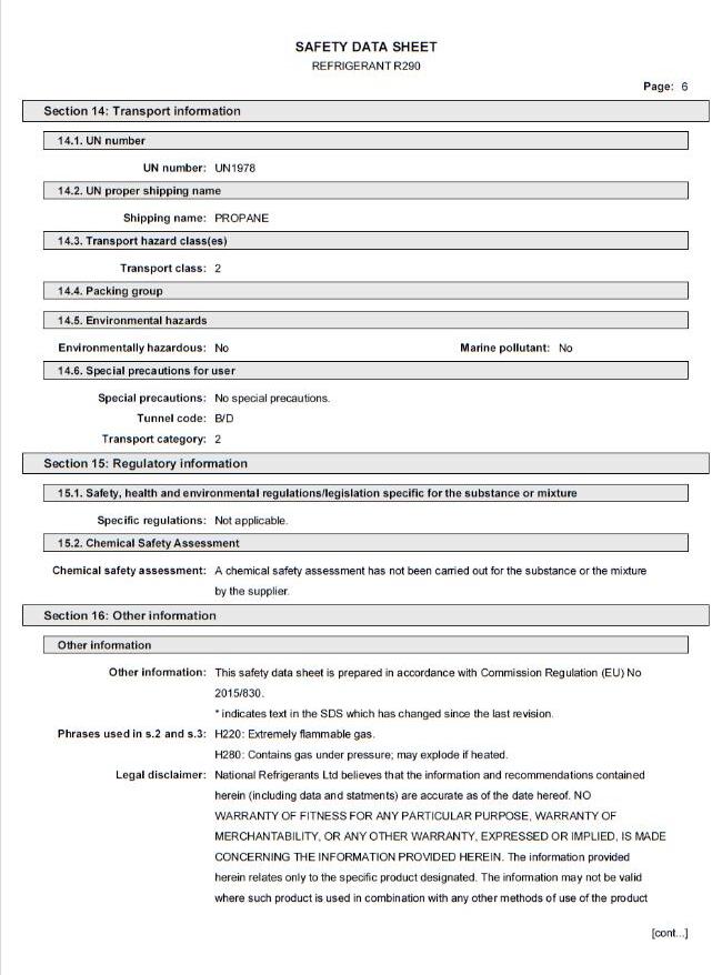
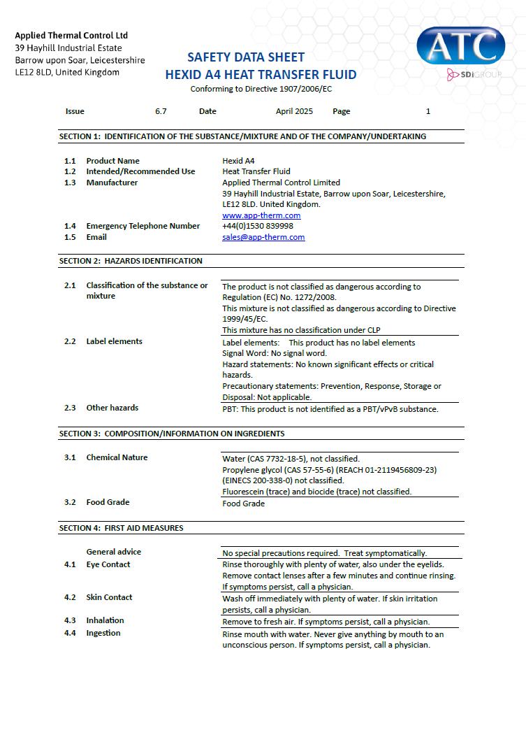
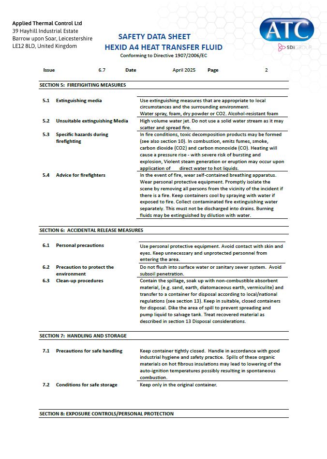
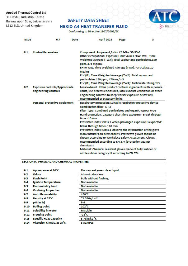
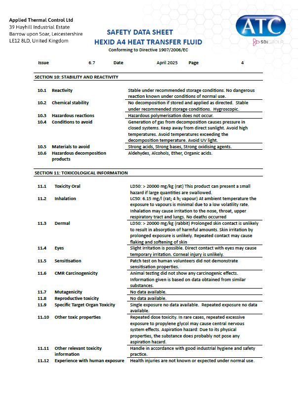
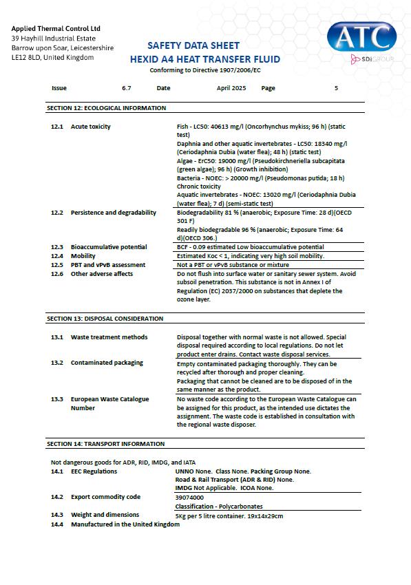
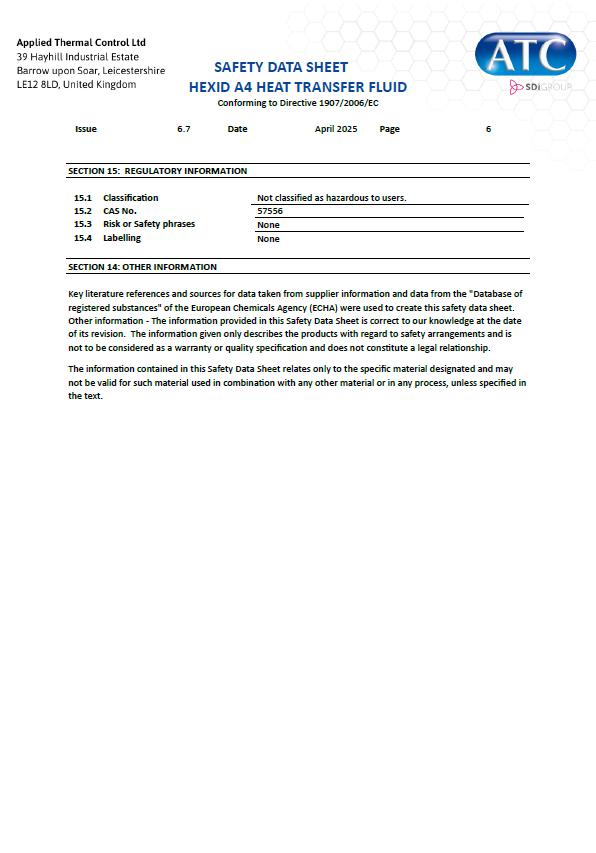
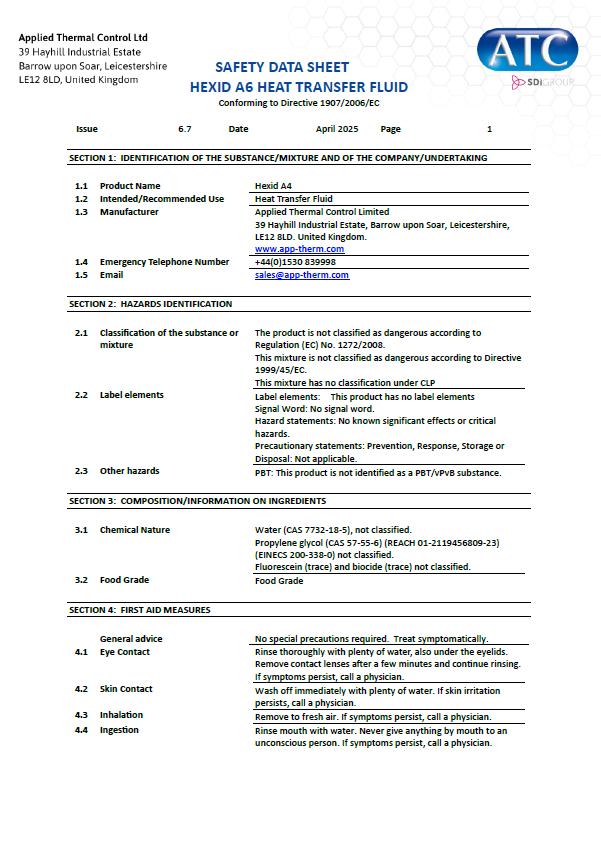
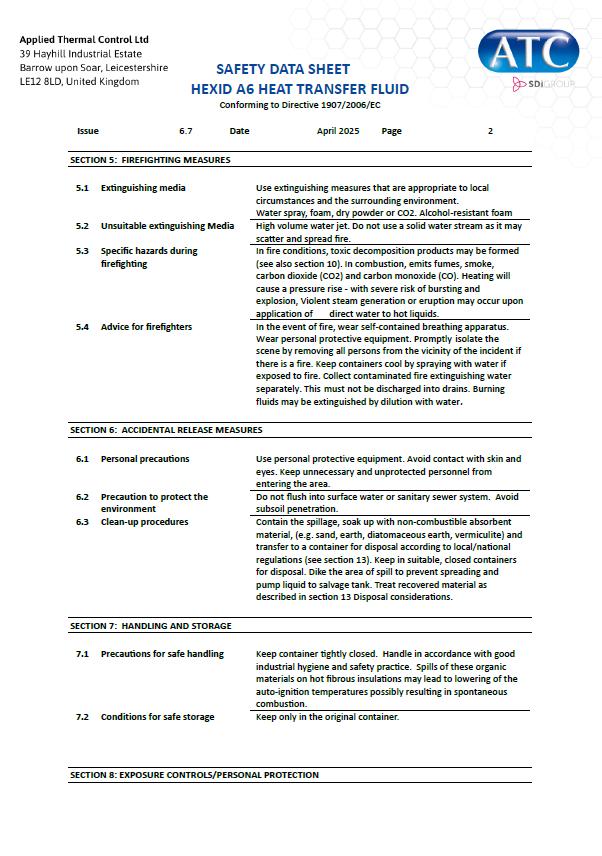
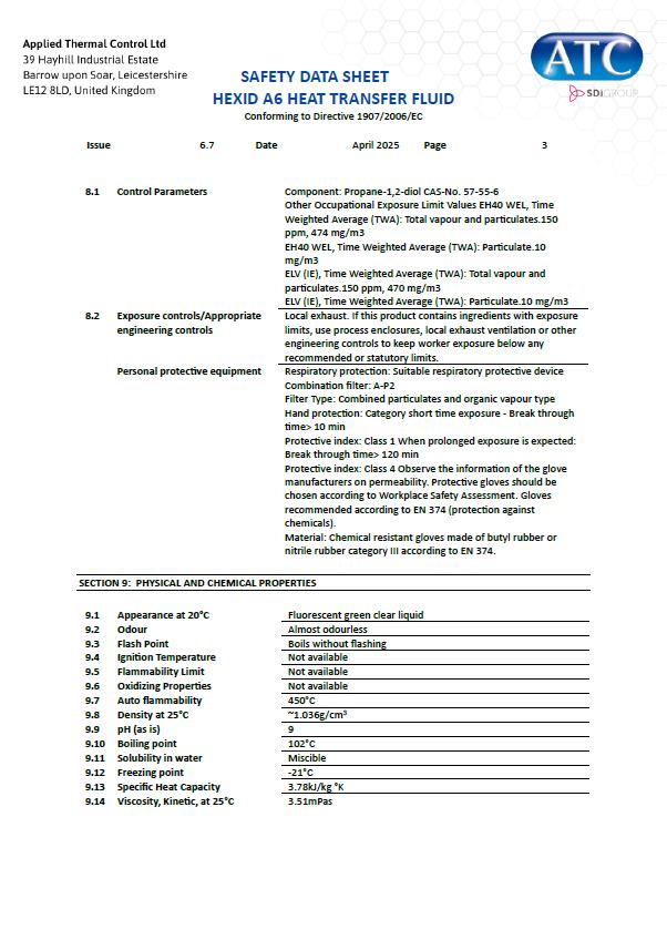
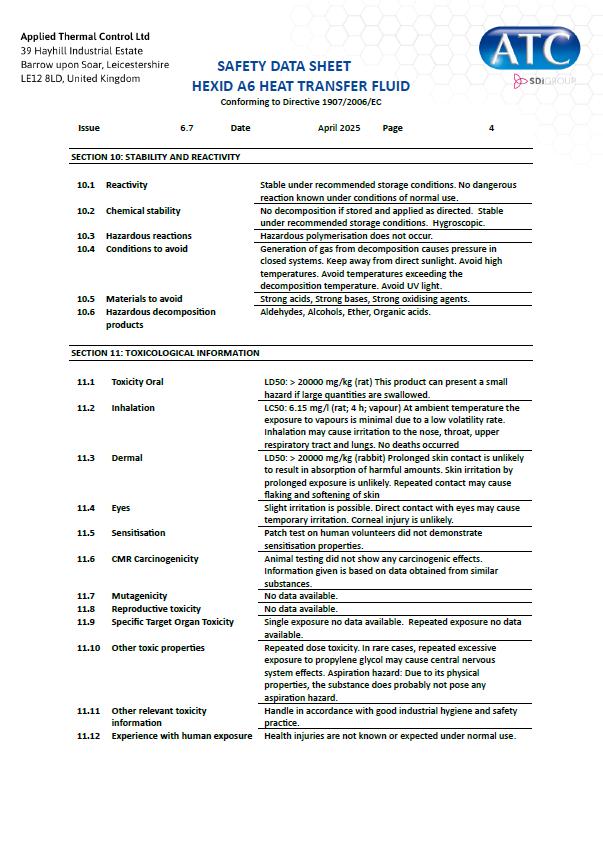
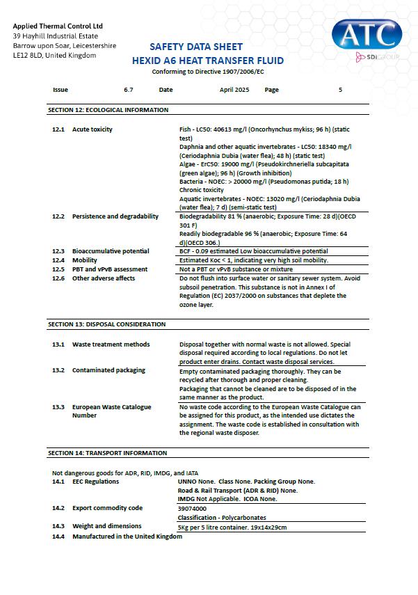
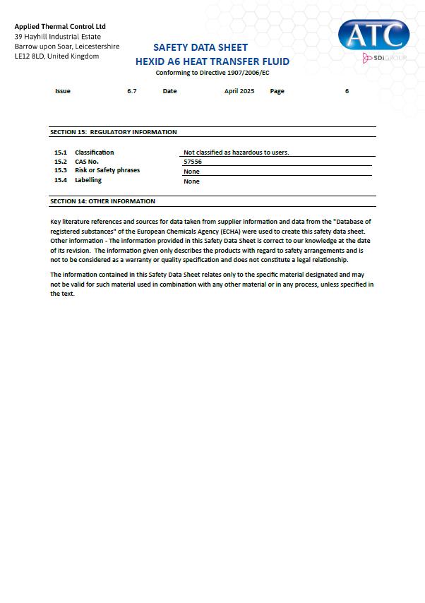
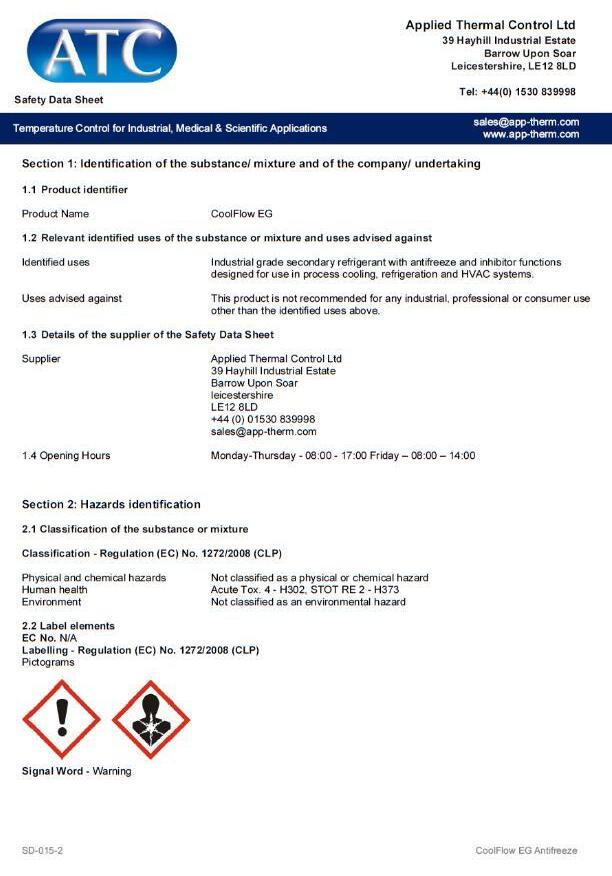
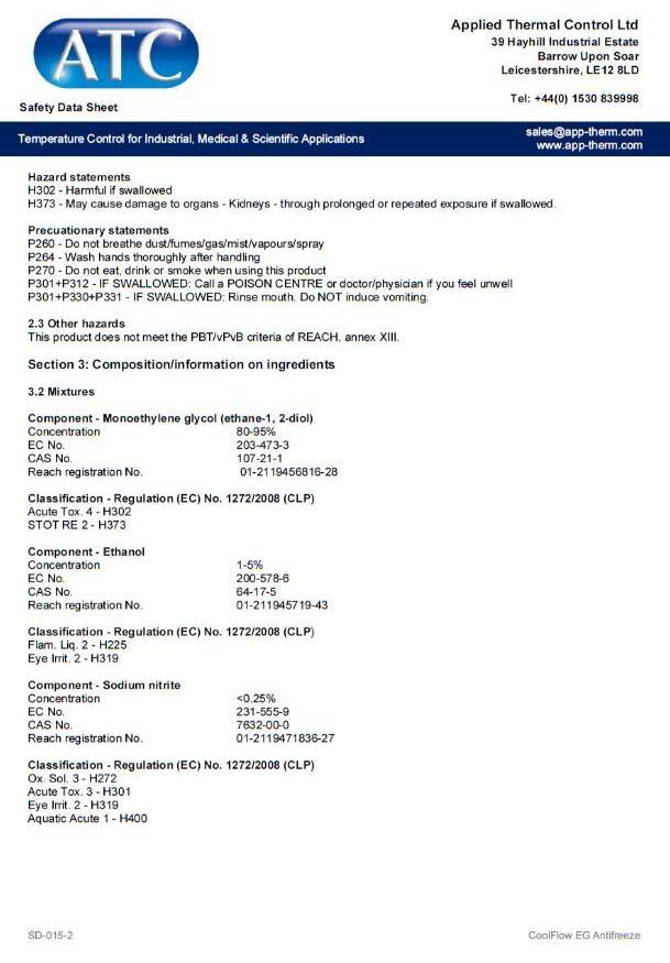
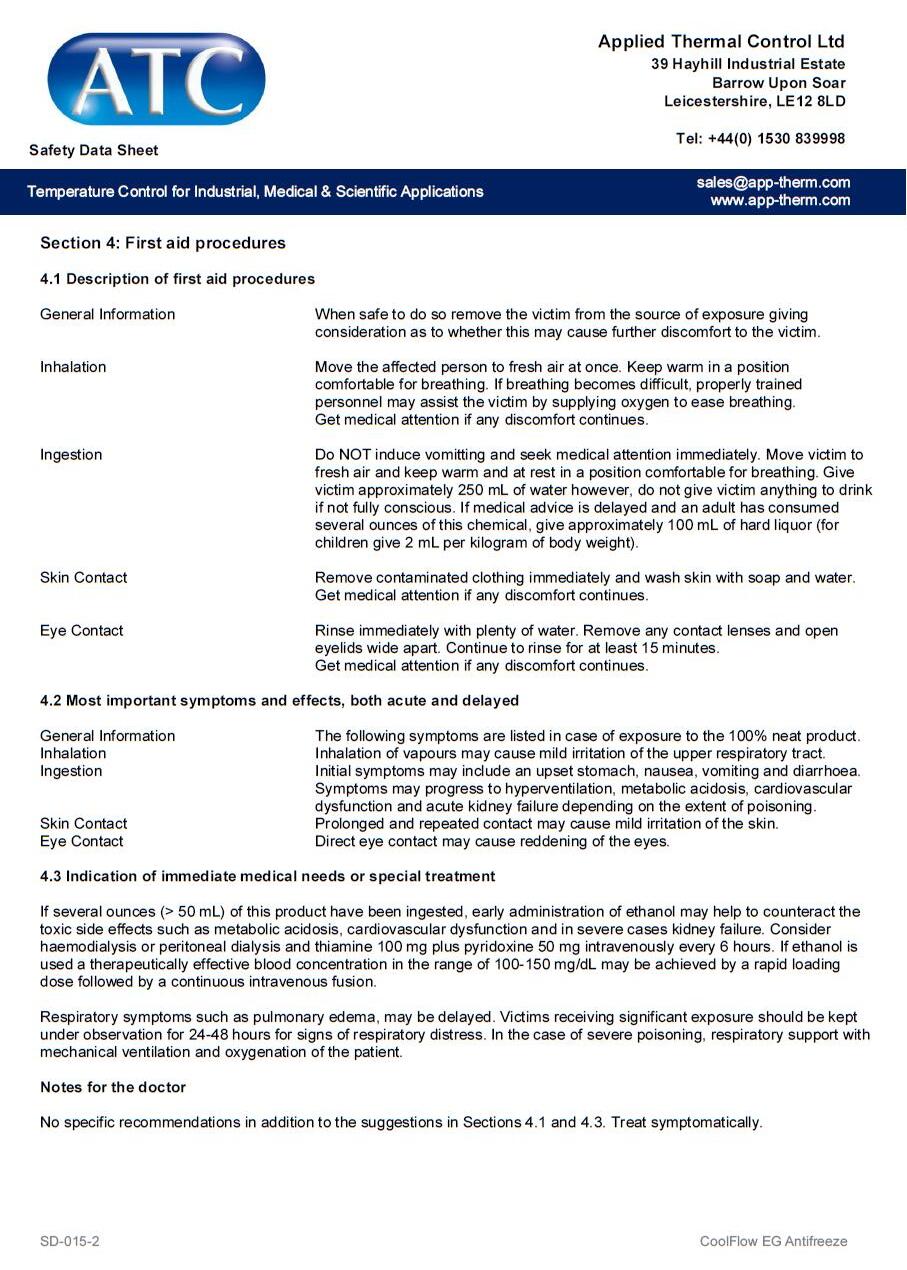
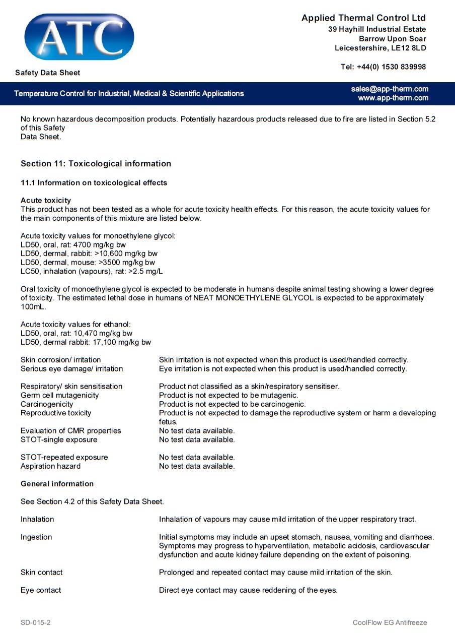
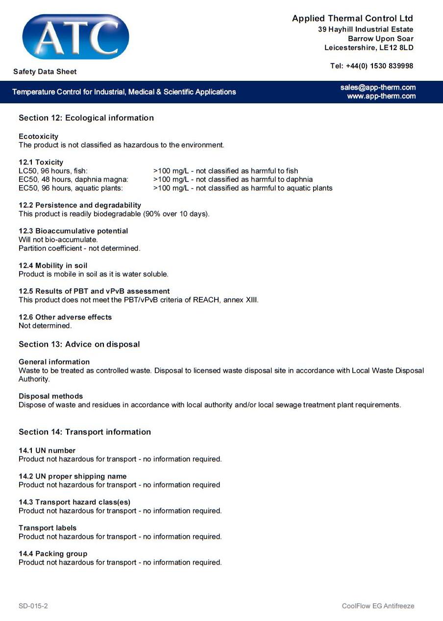
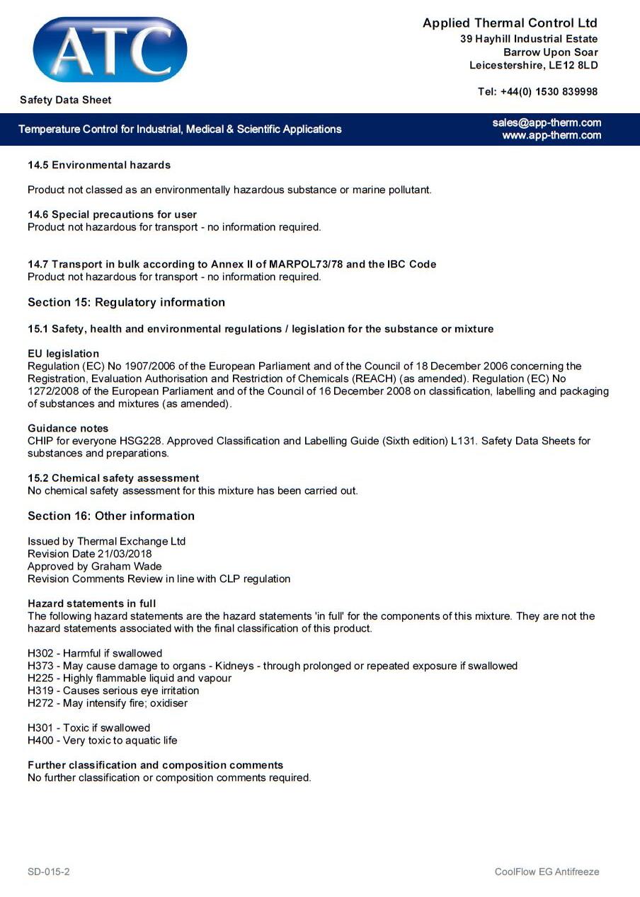
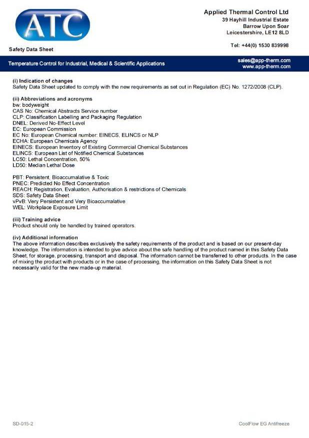
10.0 REFRIGERANT & HEAT TRANSFER FLUID SAFETY
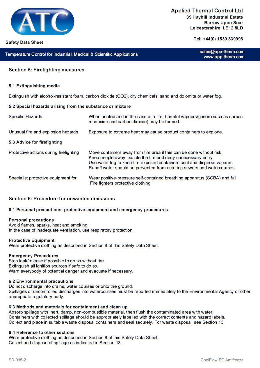
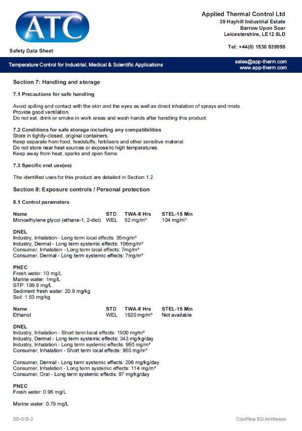
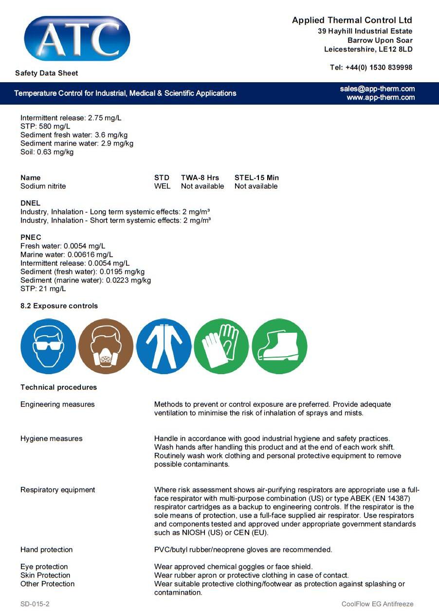
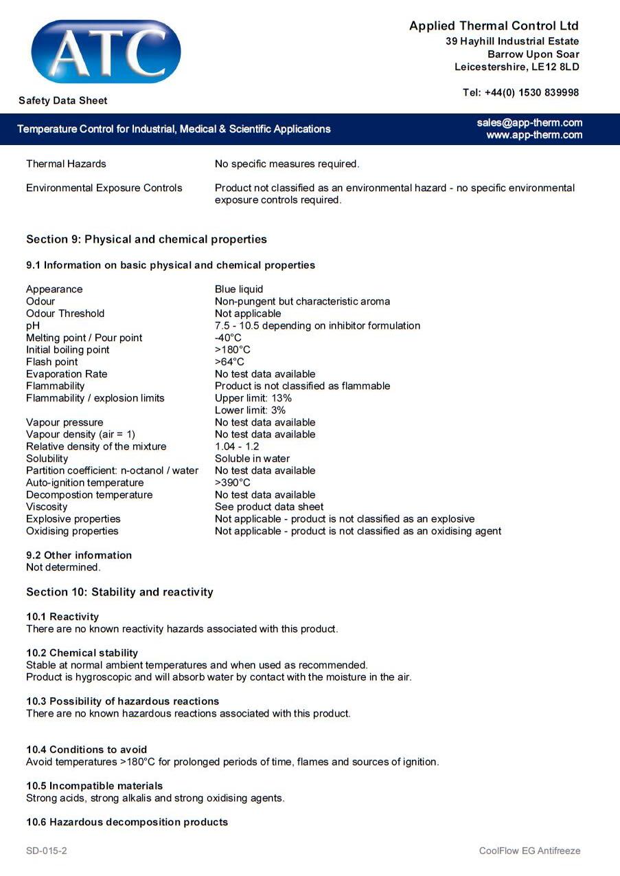
DATA SHEETS
Safety Data Sheets in the below sections for the refrigerant used in your product, along with ATC heat transfer fluids. For further information on which heat transfer fluid is best for your application, please contact Applied Thermal Control.