(0)1530



1.0 Introduction
By selecting a K series chiller, you have invested in many years’ experience in the design and manufacture of precision temperature control instrumentation.
ATC has built your K series chiller without compromise to meet the objectives of performance and reliability. Please read this manual carefully to ensure you understand the operation of the machine and how to use the unit safely and efficiently.
If you have any questions regarding installation or repair of this unit, please contact ATC direct.
Applied Thermal Control Limited
39 Hayhill Industrial Estate Barrow upon Soar Leicestershire LE12 8LD United Kingdom
Tel: +44 (0) 1530 839998 e-mail: sales@app-therm.com
Safety
For your safety we draw your attention to the following Warning and Caution statements throughout the manual.
The safe operation of a K series chiller always remains the responsibility of the operator.
Caution: Failure to comply with a Caution will invalidate product warranty and absolve ATC from any liability, howsoever caused, and could result in permanent damage to equipment.
Warning: Failure to comply with a ‘Warning’ may result in personal injury or death. ATC does not accept any liability for injury caused through use of this equipment.
Warning: No user serviceable parts.
Warning: Very hot surfaces, more than 100°C
Warning: Very cold surfaces and gases, lower than -40°C. Severe frostbite hazard.
Warning: Opening the refrigeration system may expose the operative to toxic and corrosive compounds (HFC’s). Take protective measures including suitable eye protection.
Warning: Gases may exceed 300 psi (20 bar) during operation.
Warning: All refrigerants do not support combustion and are asphyxiating gases.
Warning: After switching off, the fan blades continue to rotate. Do not attempt service whilst the blades are rotating.
Warning: All chillers contain water and electricity in close proximity. Always ensure the unit is isolated before service. All K series chillers are protected from over current by the master circuit breaker. Never bypass this component.
Caution: Filling/topping up of the tank should only be undertaken with the unit switched off, to prevent back-flooding of the fluid.
Caution: The high integrity refrigeration system contains no user-serviceable parts. Repair and service requires specialised knowledge and tools. Any unauthorised tampering with the refrigeration system automatically invalidates warranty.
1.1 Unpacking
Please check that both the packaging and the unit are undamaged. If there is any doubt, it is vital that you inform both ATC and the carrier before making a claim on the carrier. There are no hidden shipping bolts or other fixings. You should inspect the packaging for signs of transit damage before signing for the unit, and if possible unpack the unit before signing.
Once you have signed for the goods, ATC cannot be held responsible for any transit damage subsequently found.
Remove the unit from its original packaging and ensure that there is no packaging left around the cooling ducts.
Please retain all packaging in the unlikely event that the chiller needs to be returned to our local representatives.
1.2 Site requirements
• Hard, level surface. Ideally smooth to allow freewheeling of castors, which are designed for indoor use.
• Clean, dust free environment. Air-cooled chillers move large volumes of air, and large amounts of air-borne contamination will result in fouling of the condenser, reducing the capacity of the unit and in extreme cases causing a system shut-down.
• Non-condensing ambient, from +4°C to +40°C. Cooling capacity is lost above 30°C.
• Electrical supply 230V +10% (50Hz) single phase1 . For the K3 the Internal circuit breaker is rated at 15 Amps, normal operating current is 13Amps. For the K1 the Internal circuit breaker is rated at 10 Amps, normal operating current is 6Amps.
• Clearance front and rear of the unit at least 250mm.
• Plumbing to be clean and compatible with the fluid to be used. It is advisable that the minimum of right angle bends and compression fittings are used. See also section 2.0
1 Switch selectable options for operation at 208VAC 60Hz, 230VAC 50Hz and 220VAC 60Hz are available on request.
1.3 Warranty registration
Please visit the website warranty registration page to ensure ATC can offer you the best possible support;
https://www.app-therm.com/warranty-registration/
a) For how long is my ATC product under warranty?
ATC provides a comprehensive return to base 2-year parts, 1-year labour warranty from delivery as standard on all new equipment, provided it has been installed and operated in accordance with the manual.
b) Where will ATC fulfill the product warranty?
ATC’s standard warranty terms are Return to Base (RTB) – issues with chillers are often easily solvable over the phone or email, or by reviewing ATC’s technical guidance on the web and in the product manual. On occasion, at the discretion of ATC, goods may be serviced on site FOC or a service loan unit may be supplied. Warranty cover excludes the cost of travel by engineers and loan unit rental charges. Obtaining onsite service for a product, even in full warranty, is a chargeable service.
c) Who is liable for shipping charges in the event of warranty failure?
During the first year of the warranty period, freight costs to and from ATC are covered by ATC. During the second year of the warranty, freight costs to and from ATC are payable by the customer.
d) I’m experiencing problems with my chiller. It’s within warranty – what do I do next?
Contact ATC to discuss the issue you are having on +44(0)1530 839998 or support@app-therm.com. Be sure to have your model number and serial number on-hand to aid those attempting to solve remotely.
e) Telephone support couldn’t fix my chiller – what do I do next?
An RMA form must be completed. This allows both the end-user and ATC to clarify your details, to set the party responsible for shipping costs, and to set a different return address if desired. Shipping advice is provided, and the end-user must sign a declaration that states the unit is safe to handle. Return the form by email for fastest response.
f) What happens if my chiller failed outside warranty or requires non-warranty repair work?
A purchase order will be requested to cover an initial inspection – this will only be invoiced if the inspection shows there is no fault. If packaging is required, i.e. a crate, a separate charge will be levied. If the end user prefers ATC to arrange a collection, a shipping charge may be levied.
g) Our process must continue running – can we have a loan unit whilst our chiller is in repair?
ATC hold several standard air-cooled chillers at the factory for the sole purpose of offering for loan These are available on a first-come, first-serve basis. Models up-to 3kW capacity are available.
K3 series chillers – Installation and Operation manual
h) To avoid any delays in remedial actions in the event of a repair it is essential to retain the original packaging. Please note that if the unit is returned for repair without original packaging, a fee may be charged for the provision of replacement packaging.
2.0 Installation
Having ensured that your installation meets all the site requirements identified in section 1.3, it is best practice that the fluid lines between your application and the chiller have the following characteristics:
• Short
• Large diameter (ideally at least 12mm internal diameter)
• Free from right angle bends, to suppress water hammer
• Opaque, ideally black, to inhibit growth of algae. Alternatively, use solid copper or welded ABS. Caution: Never use transparent tubing.
• Clean. If your installation is to existing pipe work, it is good practice to flush the system with either a commercially available central heating cleaner or 5% acetic acid solution. The system should be flushed clean with tap water to remove all traces of cleaner prior to filling the system.
All connections should be made using either the ATC ‘easy clamp’ or a jubilee type clip. Where threaded or compression type fluid joints are to be made, always use a suitable jointing compound such as PTFE tape.
Voltage selection
Caution: If your K1 or K3 series chiller is rated for multi voltage and dual frequency operation it may have a transformer and internal voltage selection switch. It is essential that the voltage selector switch on the chiller is set to match the voltage and frequency available at your site.
On the K1 Chiller the voltage selector switch can be found on the left side of the chiller when viewed from the front, mounted on the vertical support located behind the removable side cover. Access is gained by removing the side cover completely to expose the selector switch. Always replace the cover for normal operation.
On the K3 Chiller the voltage selector switch can be found under the access port in the top of the chiller, mounted on the rear of the electrical box. Access is gained by removing the assess port to expose the selector switch. Always replace the port for normal operation.
Having ensured that the system is correctly connected, with the inlets and outlets having the correct orientation relative to your application, all joints tight and leak free, and with the unit isolated from the electrical supply, prepare to fill the unit with Hexid fluid.
Hexid fluids are the preferred coolant choice as they provide excellent corrosion protection, freeze protection, algae inhibition and good heat transfer properties.
Caution: Always use ATC recommended fluids in your K series chiller. Never use other antifreeze mixtures, as they may corrode your application and will damage the K series pump seals.
Filling procedure
1. Check all valves are open, including solenoid valves located in your application.
2. Remove the filler access door in the top cover, then remove cover from the tank
3. Fill with Hexid to just below the rim of the tank neck.
4. Switch the unit on.
5. Wait while the fluid level drops in the tank.
6. Switch the unit off.
7. Repeat steps 3 to 5 until all the air has been purged from the system.
8. Top up to 30mm below the rim of the tank neck to ensure the level switch is made.
9. Check the system carefully for leaks, including the inside of your application. The system is now ready to be run.
Warning: Always isolate the chiller from the electrical supply when filling the tank.
3.0 Operation
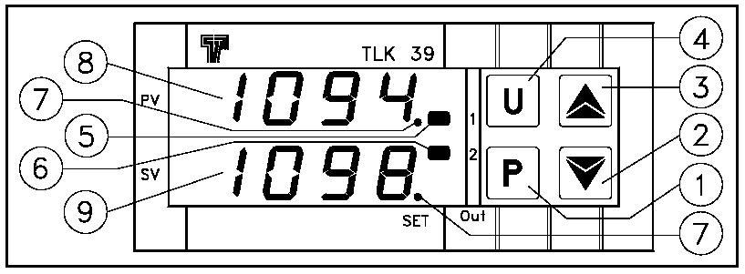
K series chillers are fitted with a high performance 3 term PID controller, which is capable of controlling temperature to within 0.1°C of set point. In addition, there is a high and low temperature warning via the LED on the display (5) of the controller, which is triggered if the temperature deviates more than 10°C from the set point.
3.1 – Changing the Set Point


This procedure permits rapid programming of the active Set Point and possibly the alarm thresholds.
Push the ’P’ button (1), then release it. The display will flash ‘SP 1’.
To modify the set point, press the ‘UP’ button (3) to increase it or the ’DOWN’ button (2) to decrease it.
Once the new set temperature is displayed Push the ’P’ button (1), then release it. The value is stored automatically after approximately 10 seconds, ‘SP 1’ will continue to flash during this time.
K1, K3 series chillers – Installation and Operation manual
K 39 Controller error messages
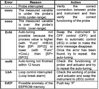
If the set point is moved more than 10°C the alarm may be triggered. The alarm resets when coolant temperature cones within 10°C of the set point. It is not possible to set the temperature outside the pre-set values of +4°C and +35°C.
3.2 – Changing the Flow and Pressure
K series chillers contain a high pressure volumetric pump capable of 150 psi. All units are supplied with a pre-set maximum of 50 psi. Pressures above this will cause the internal safety bypass valve to open, protecting your application from potentially dangerous pressures.
It is possible for customers to change the operating pressure of the chiller, as follows:
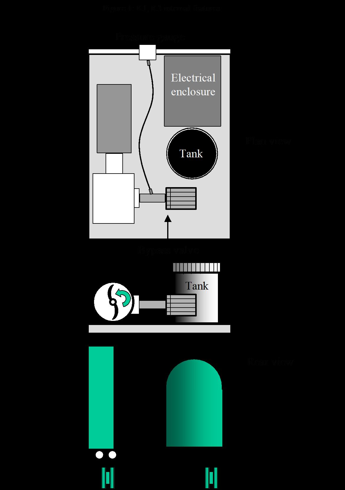
• Remove the top panel (K1) or left side panel {viewed from the front} (K3) from the chiller by removing 2 screws at the rear of the panel.
• With the chiller running, release the locking nut on the pressure relief valve; a grey valve located at the right side of the chiller, as viewed from the front.
• Turn the valve knob anticlockwise to reduce the flow/pressure, clockwise to increase the flow/pressure. Re-tighten the lock-nut.
• The pressure can be observed on the gauge on the front panel.
Caution:
Changing the flow/pressure with the pressure relief valve will also change the pre-set pressure safety setpoint. This will move to a lower pressure than the factory setting when decreasing the flow/pressure, and to a higher pressure when increasing the flow/pressure.
Caution:
When the flow/pressure is manually increased with the pressure relief valve, the safety provided by the valve will be affected at higher pressures than standard. For this reason, please ensure that it is safe for your application to operate at pressures in excess of 50 psi, even if the pressure setting on the chiller reads lower than this. A blockage in your application could result in the pressure exceeding the raised safety pressure, and while the K series chiller is tested to 120 psi, your application may not be safe at this pressure. We recommend that pressures exceeding 100psi must never be used.
4.0 Maintenance and service requirements
Caution: Failure to carry out service at the specified intervals may permanently damage your equipment.
Interval Actions
Weekly Check fluid level
Monthly Check the condenser (air intake) is free from obstructions or accumulations of debris. Cleaning may be achieved with a domestic vacuum cleaner with brush attachment.*
Annually Change the fluid. Check for fluid leaks throughout the whole system. Check the condenser for fouling.
* Caution: Never blow the condenser out with compressed air.
4.1 Status lights and troubleshooting
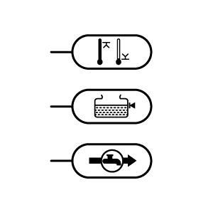
The status panel on the front of your K series chiller is fitted with three lights, configured such that ‘three lamps are good’; i.e. when they are lit, the parameter is operating within design limits.
If an indicator light is not lit, this indicates an alert situation with the corresponding parameter, as follows:
Symptom
Causes
Compressor not running, but fan running Is the controller displaying an alarm?
If there is no obvious cause, check…
• The condenser is clean
• Ambient not too high
• No temporary power failure
The likely cause is the compressor’s internal protection has been activated and should restart in five minutes.
Noisy operation / High fluid pressure And/or low flow
Fluid lines becoming fouled brown or green
Fluid seen leaking from system
Poor fluid flow
Poor cooling
Check:
• Filter, if fitted
• No restrictions in the pipe work
• Operating coolant pressure set too low
Clean fluid path with weak detergent solution, flush and replace fluid with correct Hexid fluid.
Algae contamination.
Clean system with weak detergent solution, replace fluid lines with opaque (ideally black) lines to inhibit algae growth. Use Hexid fluid.
Under high humidity conditions, fluid may appear to be leaking from the system. This is usually just condensation, but it is always prudent to check for fluid leaks.
Flush with clean water, replace fluid with Hexid.
Check fan is rotating continuously
Almost always caused by blocked condenser.
Clean with soft brush or vacuum cleaner with brush attachment
Continued failure may indicate high ambient or excessive load applied to the unit. Check these first
5.0 Return of goods procedure
If the unit is damaged during transit, or subsequently develop a fault requiring its return to ATC, the following procedure must be followed.
1. Call the ATC service point on +44(0)1530 839998 or email sales@app-therm.com.
• You will be issued with a Return Materials Authorisation number (‘Q number’).
2. Return the completed RMA form to ATC, together with your purchase order number.
3. Pack the returning item securely, enclosing a copy of the completed RMA form, and ensure that the packaging is clearly labelled with the Q number. Neither ATC nor your shipper will be liable for any damage incurred in transit.
4. Upon receipt of the completed RMA form, an engineer will be allocated or a service loan unit* will be despatched if available.
* Please note that ATC will raise an invoice as part of the service loan procedure, and you will receive a credit against this upon the safe return of the loan unit.
Address for return units:
Applied Thermal Control Limited Goods Inward
39 Hayhill Industrial Estate
Barrow upon Soar Leicestershire
LE12 8LD United Kingdom
6.0 Dimensions and performance
Cooling Capacity 1750 Watts 3200 Watts
Dimensions H x W x D 575 x 420 x 545 mm 720 x 550 x 560 mm
Weight 66 Kg
Kg Temperature range 4°C - 35°C 4°C - 35°C
Pumps available P5, P10, P17 P5, P10, P17
LED temperature display 0.1°C resolution standard. 0.1°C resolution standard.
Temperature control Microprocessor P.I.D. Microprocessor P.I.D.
Pressure gauge Standard Standard
Fluid connections
stability
3/8” and ½” barb supplied Custom connections available
3/8” and ½” barb supplied Custom connections available
Power requirements 6 Amps, 230V 50Hz 13 Amps, 230V 50Hz
Warranty 2 years parts, 1 year labour 2 years parts, 1 year labour