Date 12/06/2024

Date 12/06/2024
Page 1
Earlier documentation may have indicated that the use of tap water in ATC chillers was permissible under certain conditions. Based on further evaluation and our ongoing commitment to system reliability, we now advise against the use of tap water in any ATC chiller models. This updated recommendation reflects a more comprehensive understanding of global water quality variation.
Water quality can vary widely by region and application. Tap water may contain:
• High mineral content (e.g. calcium, magnesium)
• pH imbalance
• Biological matter (e.g. algae, bacteria)
• Chemical additives (e.g. chlorine, fluoride)
These factors can contribute to:
• Internal corrosion
• Degradation of seals and materials
• Biological fouling
• Reduced heat transfer performance
As such, continued use of unapproved fluids, including untreated tap water, may affect long-term performance in some instances.
To support the ongoing reliability and efficiency of ATC chillers, we recommend using only ATC-approved fluids.
Hexid - Providing corrosion protection, freeze protection, algae inhibition, and effective thermal performance.
If Hexid is not available in your region, please contact ATC for guidance.
For questions regarding coolant compatibility or fluid selection for your specific system, please contact ATC Technical Support.


Applied Thermal Control Ltd
39 Hayhill Industrial Estate
Barrow-upon-Soar, Loughborough
LE12 8LD, United Kingdom
+44 (0) 1530 839 998
Service@thermalexchange.co.uk
Support@app-therm.com
Date 9/SEP/2022 Author(s) MJH
LE12 8LD, United Kingdom
+44 (0) 1530 839 998
Service@thermalexchange.co.uk
Support@app-therm.com
Applied Thermal Control Ltd
39 Hayhill Industrial Estate
Barrow-upon-Soar, Loughborough
LE12 8LD, United Kingdom
+44 (0) 1530 839 998
Service@thermalexchange.co.uk
Support@app-therm.com
Max. Total Heat Rejection Applied load, plus power in Applied load, plus power in Applied load, plus power in Max. permissible return line temperature +65°C
Pump options P25, P40, P80
Pressure relief None
1st party approvals CE, UKCA CE, UKCA CE, UKCA
3rd party approvals UL-ready UL-ready UL-ready
Empty fluid reservoir alarm Standard, process stop
process stop
process stop Low fluid flow alarm Optional
display Optional
Temp out of range alarm Optional
Thermal overload alarm
process stop
Cooling system Single axial fan
Overcurrent protection Standard, via GV2 breaker
process stop
axial fan
via GV2 breaker
process stop
axial fan
via GV2 breaker
Overcurrent fault-cleared restart mode Manual restart Manual restart Manual restart
Interlock-restored restart mode
by default. Automatic available as option.
Date 9/SEP/2022 Author(s) MJH
For your safety, we draw your attention to the following warning and caution marks throughout the manual Warning symbols can be found on the unit. Ensure you have read through all warnings before starting the unit. The safe operation of ATC products always remains the responsibility of the operator. This equipment is intended to be used as a liquid temperature conditioning device – it requires no external pump, nor any further manipulation of temperature. If the equipment is used in a manner not specified by the manufacturer, the protection provided by the equipment may be impaired. Failure to comply with a ‘warning’ may result in personal injury or death. ATC does not accept any liability for injury caused through use of this equipment.


Caution; Failure to comply with a caution will invalidate product warranty and absolve ATC from any liability, howsoever caused, and could result in permanent damage to equipment.
Caution; Filling/topping up of the tank should only be undertaken with the unit switched off, to prevent back-filling of the fluid.
Caution; This product contains no user-serviceable parts. Repair and service requires specialized knowledge and tools to be provided by ATC or its local agent. Any unauthorized tampering with the heat exchanger system automatically invalidates warranty.
Warning; Hot and cold surfaces are present during operation. Take caution and care when touching pump during operation.
Warning; Water pressures of up to 10 bar during operation.
Warning; Water and electricity near one another. Always ensure the unit is isolated before service. The product is protected from overcurrent by GV2-type overload device. Never bypass this component.
During fault diagnostics and maintenance, it may be necessary to remove panels, which expose the operator to the dangers of pressurized systems, hot or cold pipes and electrical circuits. Only qualified personnel who are aware and equipped to deal with these systems should only carry out such work.
Any temporary electrical supply to the chiller should be correctly earthed and connected through an earth leakage trip.
In case of unexpected coolant leakage, safety glasses should always be worn when the chiller is operated with the covers removed.
Under no circumstances leave the cooler unattended with the side panels removed.
Never alter settings of pressure switches, overloads, circuit breakers or any safety device without first consulting Applied Thermal Control.
Service@thermalexchange.co.uk
Support@app-therm.com
Date 9/SEP/2022 Author(s) MJH
Specific technical product information is provided in the following series of annexes.
Annex A-3 201105 Shipping _ Unpacking - Crane or forklift required
Annex B-7 220909 Site _ Environmental Requirements for A20 A40 A80
Annex C-5 220309 Installation - Generic air-cooled with 1.5inch fittings
Annex C-8 220309 Installation - Generic air-cooled with 1.0inch fittings
Annex D-10 220909 Fluid Handling _ Startup Procedures - A20 A40 A80
Annex E-0 211203 No controller
Annex F-5 220610 Centrif or turbine pump without relief
Annex F-6 220311 Centrif or turbine pump using throttling valve
Annex G-10 220309 Troubleshooting - Initial help for A-Series
Annex H-1 191121 End-user maintenance - air-cooled units with water as fluid
Annex I-7 220310 Maintenance for technicians - Generic airblast
Annex J-5 200706 EU Compliance Statement Conflict Minerals
Annex J-6 220406 EU DoC A-series
Annex J-7 200715 EU Compliance Statement REACH
Annex J-8 200827 EU Compliance Statement POPs
Annex J-10 201111 EU Compliance Statement RoHS
Annex J-17 220310 UKCA DoC A-Series
Annex K-1 200623 Standard warranty terms of ATC
Annex L-3 211130 Heater pack general application
Annex L-11 210528 KR1 KR3 RS485 Modbus RTU Protocol
Annex L-12 220610 Volt Free Contacts
Annex L-24E 210301 Proportional fan speed control for A-Series
Annex L-41 211125 Frost protection
Annex L-51 220614 Remote Stop-Start
Annex M-7 220909 Recommended spares, A Series
Annex R-3 200203 SDS Hexid A4 v6.4
Service@thermalexchange.co.uk
Support@app-therm.com
Date 03/FEB/2021 Author(s) MJH / LW / AMI
Please check that both the packaging and the unit are undamaged. If there is any doubt, it is vital that you inform both ATC and the carrier. If possible, unpack the unit before signing. Once you have signed for the goods, ATC cannot be held responsible for any transit damage subsequently found.
Remove the unit from its original packaging and ensure that there is no packaging left around the cooling ducts. There is no internal product packaging that requires the product to be opened.
When moving the unit, ensure pallet truck or forklift are rated appropriately for weight. Moving the unit off the pallet should be done with either a forklift (using forklift guide channels if present on your product) or slings and a crane (unless lifting eyebolts (craning points) are present on your product). Positioning the unit on the shopfloor can be achieved by moving on castors (if present) or using a pallet truck – if your unit has rigid feet, once positioned, screw down the four adjustable floor pads until the weight is taken off the castors. Tighten the locking nuts when adjusted.
Please retain all packaging in the unlikely event that the chiller needs to be returned to our local representatives.
+44 (0) 1530 839 998
Service@thermalexchange.co.uk
Support@app-therm.com
This guide applies to certain A-Series products only. Please find below the requirements for all services and conditions necessary for years of trouble-free running. If you require more detail, please contact ATC for support on sales@app-therm.com or using the contact information at the top of this page.
1 Storage temperature range. Without process fluids, -20°C to +70°C.
Storage humidity range. Non-condensing, relative humidity 5% to 95%. Before starting product, allow product to acclimate for 24h in location of use when storing outside operating humidity range. 3
Operating temperature range. With appropriate process fluids, -20°C to +65°C. 4
Operating humidity range. 80% for ambient temperatures up to +31°C (+88°F), decreasing linearly to 50% relative humidity at +40°C (+104°F) ambient temperature.
5 Hard, level surface. A level surface is important for ensuring proper filling and allowing air to escape.
Clearance. Clearance is required to;
a) Provide unobstructed access to the electrical box door to use overload handle in case of emergency.
b) Fit hoses and electrical supply to the side of the unit allowing recommended bending radii.
c) Allow maintenance access points on side panels to be removed.
d) Allow process to take place – all models require the coolest, cleanest air that can be provided to achieve the best performance. All models draw air in from the lower left-hand face (when looking at the facewith electrical box door) and reject heated air to the lower right-hand face.
0.5m clearance is recommended on air-on, electrical box door and air-off face.
Plumbing. Tubing, piping or hose must be clean and compatible with the fluid to be used. The product is compatible with deionized water, tap water and water-glycol mixtures such as Hexid A4 and A6. Ensure the connected pipework is suitable for handling the nominal flowrate at system pressure ≥6bar.
Indoor use only. Altitude up to 2000m above sea level. Ensure the unit has adequate ventilation.
Installation category. Transient overvoltage category II; Pollution degree 2. Temporary overvoltages occurring on mains supply are acceptable within limits defined in the categories.
Caution; Always use ATC recommended fluids in our products – many sealing compounds and materials are present and unapproved fluids have the potential to corrode your application and damage seals.
Caution; Do not use inadequately rated wiring. Consult an electrician if you are unsure.
Caution; The safety of any system incorporating the equipment is the responsibility of the assembler of the system.
Caution; Do not replace detachable mains cords with inadequately rated cords. Contact ATC for appropriately rated products.
39 Hayhill Industrial
LE12 8LD, United Kingdom
+44 (0) 1530 839 998
Service@thermalexchange.co.uk
Support@app-therm.com
Date 9/MAR/2022
This guide applies to the following product groups;
- K-, G-, W-Series refrigerated units, where heatload is rejected to air. - A-Series airblast units, where heatload is rejected to air.
Having ensured that your installation meets all site requirements, it is best practice that the fluid lines between your application and the chiller have the following characteristics.
1
2
Short in length – this reduces friction-based pressure drop and minimizes exposure to ambient heat load.
Large diameter bore – we recommend hose internal diameter (ID) on 1-1/2” BSPPF fittings is no smaller than 1-1/4” (32mm), and preferably larger than 1-1/2” (38mm). 3 Free from 90° bends – to limit the effects of water hammer. If this cannot be avoided, sharp changes of direction should be minimized so far as possible. Doing this correctly can yield higher pump performance and extend time between maintenance intervals. It will also reduce electrical energy consumption.
4
5
6
Clean – If your installation is to existing pipe work, it is good practice to flush the system with either a commercially available central heating cleaner or 5% acetic acid solution. The system should be flushed clean with tap water to remove all traces of cleaner prior to filling the system. Failing this, it is recommended to use a domestic bleach in solution with tap water, diluted to the point where the bleach can longer be smelled by human nose. ATC can offer commercial-grade cleaning solutions – contact us for information.
Opaque, ideally black – to inhibit light passing through the tube and algae building up. Alternatively, solid ABS or copper pipe can be used where application chemistry allows.
Insulation, where low temperature process is planned – the process line from chiller to application contains the feed of low temperature fluid. Insulation prevents heat from entering this line and can promote better stability. Uninsulated return lines are helpful where free cooling can be obtained by allowing heat to transfer to air – likewise, insulating the return line is helpful if the fluid temperature is below ambient.
Caution; Never use transparent tubing. UV light will pass through, prompting growth of organic contamination.
1
2
3
This document described the use of 1-1/2” British Standard Pipe Parallel Female (BSPPF) threads (also known as G threads (ISO228)) by default. These fittings are not valved and will ‘drop’ the volume of the system if left open to atmosphere.
Ensure the appropriate thread sealants are used in the fitting of adapters to hose. For metallic mating parts, we recommend Loctite 577. For plastic adaptors such as those supplied with standard products, we recommend using ~8-12mm wide PTFE tape, wrapped around the male thread before tightening.
Ensure that the system is correctly connected. The ‘donut’ labels around the ports are clearly marked with inlet and outlet symbols and function in both English and French language. Ports marked as outlets mean fluid leaves the product and must be connected to the process inlet or house water return line.
4 Check all joints are tight and leak free.
5 Where this product is incorporated into other equipment, it is the responsibility of the assembler to ensure safety.
1 In situations where the chiller is situated physically lower than the application being cooled, fluid will apply pressure to the water circuit of the product.
The weakest seal is normally the tank lid, and this is typically where fluid will escape the unit.
Ideally, the product will be located higher or level with the product water-line. If this is not possible, a nonreturn solenoid valve kit can be installed as an optional standard assembly.
4 Please raise any questions with the sales team on sales@app-therm.com
+44 (0) 1530 839 998
Service@thermalexchange.co.uk
Support@app-therm.com
Date 9/MAR/2022
This guide applies to the following product groups; - K-, G-, W-Series refrigerated units, where heatload is rejected to air. - A-Series airblast units, where heatload is rejected to air.
Having ensured that your installation meets all site requirements, it is best practice that the fluid lines between your application and the chiller have the following characteristics.
1 Short in length – this reduces friction-based pressure drop and minimizes exposure to ambient heat load.
2 Large diameter bore – we recommend hose internal diameter (ID) on 1” BSPPF fittings is no smaller than 3/4” (19mm), and preferably larger than 1” (25.4mm).
3 Free from 90° bends – to limit the effects of water hammer. If this cannot be avoided, sharp changes of direction should be minimized so far as possible. Doing this correctly can yield higher pump performance and extend time between maintenance intervals. It will also reduce electrical energy consumption.
4
5
6
Clean – If your installation is to existing pipe work, it is good practice to flush the system with either a commercially available central heating cleaner or 5% acetic acid solution. The system should be flushed clean with tap water to remove all traces of cleaner prior to filling the system. Failing this, it is recommended to use a domestic bleach in solution with tap water, diluted to the point where the bleach can longer be smelled by human nose. ATC can offer commercial-grade cleaning solutions – contact us for information.
Opaque, ideally black – to inhibit light passing through the tube and algae building up. Alternatively, solid ABS or copper pipe can be used where application chemistry allows.
Insulation, where low temperature process is planned – the process line from chiller to application contains the feed of low temperature fluid. Insulation prevents heat from entering this line and can promote better stability. Uninsulated return lines are helpful where free cooling can be obtained by allowing heat to transfer to air – likewise, insulating the return line is helpful if the fluid temperature is below ambient.
Caution; Never use transparent tubing. UV light will pass through, prompting growth of organic contamination.
This document described the use of 1” British Standard Pipe Parallel Female (BSPPF) threads (also known as G threads (ISO228)) by default. These fittings are not valved and will ‘drop’ the volume of the system if left open to atmosphere.
2
3
Ensure the appropriate thread sealants are used in the fitting of adapters to hose. For metallic mating parts, we recommend Loctite 577. For plastic adaptors such as those supplied with standard products, we recommend using ~8-12mm wide PTFE tape, wrapped around the male thread before tightening.
Ensure that the system is correctly connected. The ‘donut’ labels around the ports are clearly marked with inlet and outlet symbols and function in both English and French language. Ports marked as outlets mean fluid leaves the product and must be connected to the process inlet or house water return line.
4 Check all joints are tight and leak free.
5 Where this product is incorporated into other equipment, it is the responsibility of the assembler to ensure safety.
1 In situations where the chiller is situated physically lower than the application being cooled, fluid will apply pressure to the water circuit of the product.
The weakest seal is normally the tank lid, and this is typically where fluid will escape the unit.
Ideally, the product will be located higher or level with the product water-line. If this is not possible, a nonreturn solenoid valve kit can be installed as an optional standard assembly.
4 Please raise any questions with the sales team on sales@app-therm.com
a) Check all application valves are open, including solenoid valves and variable position valves.
i) The product will require an open water circuit to pump into
ii) Any obstructions can increase the time, or entirely prevent the bleeding of air from the system.
b) Remove the cap from the fill port on the side of the product.
i) Fill the tank to the line marked on the sight tube, visible on the same face as the fill port.
c) Turn your attention to the main power switch.
i) Immediately after rotating this switch assuming that the supply is on, the product will begin to pump.
ii) Leave the product to run until it cuts out on the level switch interlock.
iii) Turn the unit off at the mains handle.
iv) Fill the tank again to lift the level switches.
v) Start the product again until the unit cuts out again.
Caution; Do not run the pump dry. Do not deadhead the pump.
d) Repeat steps at c) until the cooler tank water level (if visible) doesn’t drop, and the cooler doesn’t cutout on its level switches.
e) With the unit now running;
i) Leave the cap off the fill port for >30mins to allow air to escape, or very loosely screwed on to prevent water splashing out of the tank
f) Check the application and tubing for signs of leaks whilst the cooler is running.
i) Replace the tank lid fully when satisfied the system is full and bled of air.
1
Open the access panel on the opposite face to the electrical box door – you will have the back of the tank directly in front of you. A tee fitting in the tank will be visible – one hose end goes to the sight-tube, the other end goes through a hose to a small service valve that upon rotating through 90° will start to drain the tank.
2 Once the unit is drained, return the drain valve to the ‘stop’ position – any fluid remaining in the tank will need to be siphoned manually – it is not possible to fully empty the tank.
3
4
Some fluid will drain from connected hoses – ATC can provide valved quick release connectors to prevent cooler draining further from the internal hoses. Without quick release connectors, fluid will leave the unit under gravity. There may still be a small amount of fluid in the system; ATC recommend re-fitting the red plastic blanking plugs to prevent fluid escaping during movement of the cooler.
Local rules affect where fluid can be disposed of – ensure hazardous products do not enter the water course and are reclaimed from the unit for professional disposal.
+44 (0) 1530 839 998
Service@thermalexchange.co.uk
Support@app-therm.com
This guide may apply to your product if it is designed for continuous cooling or heating without any form of regulation, i.e., basic airblast products and KTR.
1
2
Some cooling technologies, such as airblast, are inherently safe when left to run without regulation. The worst an airblast can do to a process fluid is bring it down to ambient temperature. Naturally, a lot depends on where the airblast cooler is placed. The same is feasible with an unregulated water-to-water product, although at time of writing, ATC do not make unregulated water-to-water heat exchangers.
In a refrigerated system, such as ATC’s KTR family, there is a valve that limits the lowest temperature the chiller can reach. These valves are robust and maintain their regulating ability over the lifetime of the product. They can be adjusted to allow sub-zero operation; the operator must ensure appropriate process fluids are used to avoid freezing.
Service@thermalexchange.co.uk
Support@app-therm.com
This arrangement comprises a centrifugal or turbine type pump without any form of flowrate control or pressure relief downstream of the pump discharge. Without any relief, it is critical to ensure the pump is not deadheaded. In systems with low-pressure pumps and no control valves in the connected application, this approach provides a simple and cost-effective water circuit, albeit one more prone to failure through lack of safety devices. This annex describes ATC’s default settings and how to adjust the system.
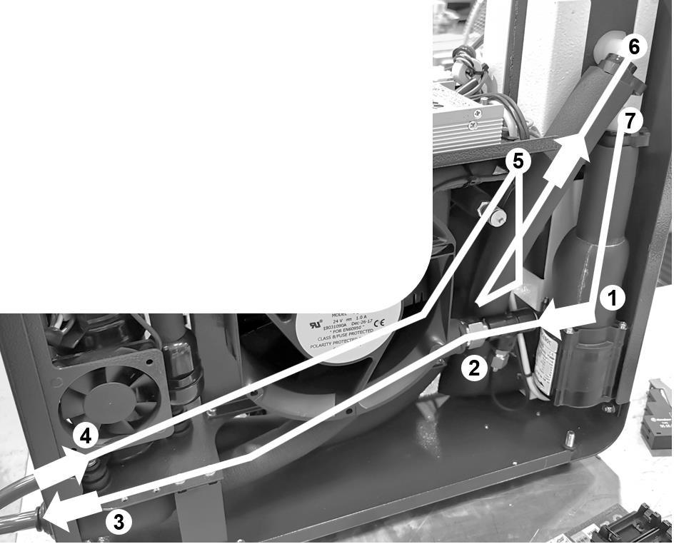
It is important to understand the basic principle that all else being equal, higher flow results in a higher demand for pressure to overcome forces of friction and viscosity. The pump motor generates the motive force required to turn the pump head and create that pressure.
B The more restrictive a water circuit is, the higher the pressure required to maintain flowrate. Centrifugal and turbine-type pumps are designed to generate lower pressure and higher flowrates. They are mechanically loose which usually leads to a longer lifetime in service.
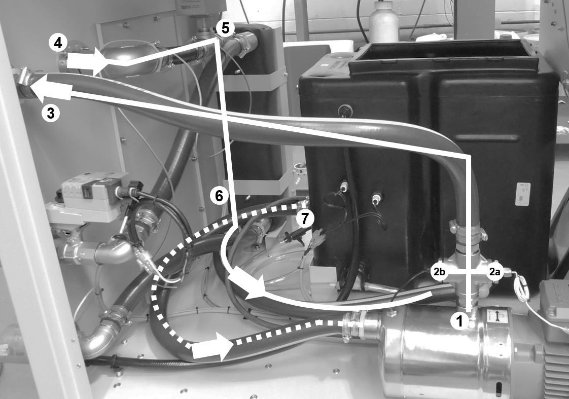
1 Pump discharge – centrifugal is gravity fed and discharges at 90deg to the inlet.
2 Temperature sensor – may or may not be present on your unit, but temperature is governed at the outlet.
3 Front outlet bulkhead fitting – see Annex C for specific information about connecting to the unit.
4 Front inlet bulkhead fitting (hidden) – as above.
5 Return to Plate Heat Exchanger (hidden) – layouts vary, but in this unit, we return to the PHE. Other layouts may see a return to tank or return to airblast coil.
6 Tank return – the ‘no relief’ system pictured has returned to tank. Some systems will go straight to pump.
7 Tank suction – the feed to the pump to begin the path again.
Applied Thermal Control Ltd
39 Hayhill Industrial Estate
Barrow-upon-Soar, Loughborough
LE12 8LD, United Kingdom
+44 (0) 1530 839 998
Service@thermalexchange.co.uk
Support@app-therm.com
With the following exceptions, the numbered descriptions apply as per page 1;
2a Temperature sensor – as per page 1.
2b Pressure gauge connection – normally routed to front panel.
This arrangement comprises a centrifugal or turbine type pump with typically a gate, needle or ball valve downstream of the pump discharge to throttle the pump flowrate. Without any relief, it is critical to ensure the pump is not deadheaded (no flow, and no relief). From many years of experience, ATC have found this method of maintaining a high head pressure on the pump to extend the service life and all but eliminate pump leaks. The valve is closed slowly until the desired flowrate or maximum pressure is met for the application, read from the panelmounted pressure gauge. This annex describes ATC’s default settings and how to adjust the system.
It is important to understand the basic principle that all else being equal, higher flow results in a higher demand for pressure to overcome forces of friction and viscosity. The pump motor generates the motive force required to turn the pump head and create that pressure.
B
1
The more restrictive a water circuit is, the higher the pressure required to maintain flowrate. Centrifugal and turbine-type pumps are designed to generate lower pressure and higher flowrates. They are mechanically loose which usually leads to a longer lifetime in service.
Pump suction – centrifugal and turbine pumps are not self-priming. The suction port/inlet must be flooded by a source of liquid. This is usually the tank with water line higher than pump suction.
2 Pump discharge – connection to the application –more restrictions downstream reduce flowrate.
3
4
5
Service pressure gauge – this displays the pressure between pump discharge and throttling valve. This is normally higher than the process pressure gauge. It should never be lower than 2bar.
Temperature sensor – on systems where temperature control hardware is fitted, the sensor is typically in the discharge line.
Fixed orifice throttling valve – if fully closed (fully CW) the pump is ‘deadheaded’ and will lead to damage in the short-term. If fully open (fully CCW), the pump is not restricted in any way – dependent on process pressure and flow requirements, the valve can be closed slowly until the desired conditions are reached
6
7
8
Process pressure gauge – reads the pressure in the line that is created when the customer’s application is connected.
Discharge to process – cooled/chilled water connection to the application.
Return from process – typically sent to either tank, airblast radiator or refrigeration heat exchanger.
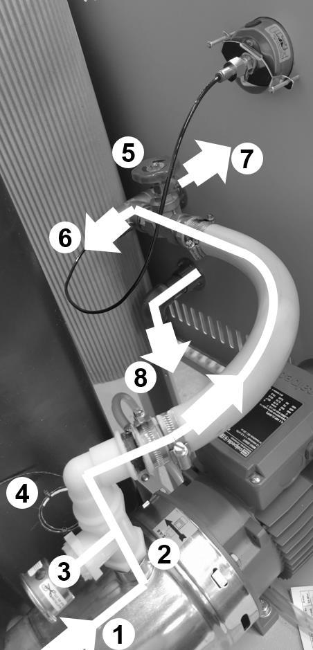
Units with this type of pressure and flow control are typically shipped fully open to prevent deadheading. When the end user or commissioning engineer first runs the unit, the full force of the pump will be available without relief – if this is likely to cause damage, the valve can be closed partially, and the service pressure gauge monitored.
2 Set the chiller/cooler running whilst connected to the application – bleed air from the system as per instruction in Annex D.
3 Using the service mounted process gauge, use pressure to determine flowrate – centrifugal and turbine pump flowrates can be determined by reading the pump curve.
4 Where pressure or flow is too high, the throttling valve can be closed down – where pressure or flow is too low, it can be opened. Typically ATC size pumps to provide some excess pressure availability.
5 Ensure the service pressure gauge is always at a minimum of 2bar.
39
+44 (0) 1530 839 998
Service@thermalexchange.co.uk
Support@app-therm.com
SYMPTOM
Unit not running
Noisy operation
Fluid lines becoming fouled / containing biological matter
Fluid seen leaking from system
Poor cooling capacity (undercooling)
Excess cooling capacity (overcooling)
Check the tank is filled past the level switch to ensure it can run.
Check temperature of fluid and pump motor. In the case of these reaching temperatures that could cause damage, the unit will switch off.
Check overload state and ensure internal fuses have continuity.
Check pump motor interlock chain.
Check supply is at correct voltage.
Air in the system the has not purged causing pump vanes to rattle (where fitted).
Bearing failure in fan or pump motor causes grinding / intermittent knocking noise.
Fan blade is running off center and grinding against coil housing.
Not using opaque tubing can lead to UV light passing through the tubing, prompting growth of organisms.
Not following maintenance schedule for cleaning/flushing.
Fluid may be incompatible with the materials used in chiller construction. Contact ATC to ensure the fluid is compatible.
Rapid changes in system temperature can cause some materials to change shape at a faster rate than others and open leak paths. Contact ATC to discuss alternative materials and parts in water circuit construction if your temperature range goes beyond the standard for this product range.
In case of centrifugal pump being fitted, minimum head of 2bar has not been observed.
Excess application thermal heat load.
See Annex G-2 for a description on how to calculate this.
Ambient air temperature has increased from nominal requirement, or flow has reduced from cooling fan.
Process fluid pump high flowrate can yield a low delta T, i.e. outlet temperature to application will be higher than desired and return temperature will be lower than nominal. Cooling capacity will be the same.
Reduction in flowrate in an airblast system without process temperature control can yield outlet temperature much closer to ambient (lower) than system design nominals. For nominals, please contact sales@app-therm.com.
One or more component in failure mode generating heat beyond that which the cooler can reject.
Cooler oversized at point of design or thermal load overestimated – this can be remedied by blocking part of the cooling coil.
Applied Thermal Control Ltd
39 Hayhill Industrial Estate
Barrow-upon-Soar, Loughborough
LE12 8LD, United Kingdom
+44 (0) 1530 839 998
Service@thermalexchange.co.uk
Support@app-therm.com
Date November 2019 Compiled by MJH
Caution; Failure to carry out service at the specified intervals may permanently damage your equipment.
Print this sheet out and display close to the chiller to maximize the visibility of maintenance requirements.
Check fluid level – top up as required.
Check the condenser is free from dust or accumulation of debris.
Drain process fluid and replace with fresh fluid.
Check for fluid leaks throughout chiller and application.
Clear any debris from inside the chiller.
A vacuum cleaner is recommended for cleaning out the condenser, while soft cloths and IPA are recommended for cleaning metallic surfaces. If any spillages have occurred, best practice is to allow the water to evaporate off and wipe up remaining glycol residue with a cloth. Always clean with power supply isolated.
Caution; Never blow out the condenser with compressed air.
Caution; If the mains lead is lost or damaged, contact ATC who will be able to supply a replacement of the correct specification.
Service@thermalexchange.co.uk
Support@app-therm.com
Date 10/MAR/2022 Author(s) MJH

Warning; Water pressures of up to 10 bar during operation.
Warning; After switching off, the condenser cooling fan blades continue to rotate. Do not attempt servicing whilst the blades are rotating.
Warning; All chillers contain water and electricity in close proximity. Ensure the unit is isolated before service. This product is protected from overcurrent by fuses (or MCB) on the mains inlet. Never bypass the overcurrent protection
Following service or repair by a trained technician;
a) Ensure any electrical connections that may have been disturbed are given the ‘tug-test’
b) Ensure earth bonding conductors are re-attached.
c) Ensure the correct fuses are in place.
d) Ensure the mains cord being used is to specification, and is free from damage
e) Subject the unit to a PAT test to ensure the unit is safe before running.
f) Ensure there are no leaks inside or outside the unit.
g) Using the wiring schematic for guidance, simulate faults to check each interlock’s function.
Date 03/FEB/2021 Author(s) MJH
Applied Thermal Control (ATC) adheres to and embraces the ethical values that support our everyday activities. As an expression of these principles and ethical values, ATC adheres to the principle of responsible sourcing of components containing precious and non-precious metals and metal salts in compliance with applicable laws and regulations.
The metals considered are Tantalum (Ta), Tungsten (W), Tin (Sn) and Gold (Au). ATC actively sources components from suppliers known to be reputable and could demonstrate compliance upon request with the Conflict Minerals acts and guidelines.
ATC uses Gold and Tin in electrical components, on PCBs and in rotating machinery, as governed by technical requirements of products. These metals could potentially originate from conflict mineral sites. As many of our suppliers do not purchase these metals direct from smelters, both they and ATC must rely heavily on information that will be provided by their suppliers to determine the source and chain of the metals in those products.
ATC is committed to working with its customers and supply chain to meet the customer’s specification and requirements with regards to traceability, sourcing requirements and restrictions. ATC commits that, to the best of our knowledge, our suppliers are complying with the conflict minerals act as stated in their documentation. These statements are reviewed, and updates obtained as required.
Mitchell Howard, Technical Manager Signed in Coalville, UK, date 6/JUL/2020
Applied Thermal Control Ltd
39 Hayhill Industrial Estate
Barrow-upon-Soar, Loughborough
LE12 8LD, United Kingdom
+44 (0) 1530 839 998
Service@thermalexchange.co.uk
Support@app-therm.com
Date 6/APR/2022 Author(s) MJH Page 22 / 68
Document layout; Governed by Machinery Directive 2006/42/EC, Annex II.
Applied Thermal Control Ltd, 39 Hayhill Industrial Estate, Barrow-upon-Soar, Loughborough, LE12 8LD, UK.
AUTHORISATION TO COMPILE THE TECHNICAL FILE
Mitchell Howard, address as above
Generic denomination; A-Series
Function; Recirculating airblast cooler
Model; All with ‘A’ prefix.
Type; Air-cooled heat exchanger
Serial number; Commercial name; As above.
Not applicable
DESCRIPTION & IDENTIFICATION
QMS International Ltd, Muspole Court, Muspole Street, Norwich, NR3 1DJ, UK. ASCB Registered; 201409-2
Applied Thermal Control declares that the machinery described above fulfils all the relevant provisions of the directives and standards below.
Directive Harmonised Standards applied
Machinery Directive 2006/42/EC (inclusive
Low Voltage Directive 2014/35/EU)
EMC Directive 2014/30/EU
RoHS Directive 2011/65/EU (RoHS 2)
RoHS Directive (EU) 2015/863 (RoHS 3)
EN ISO 12100:2010 (MD)
BS EN 61010-1:2010+A1:2019 (LVD)
IEC 61000-6-2:2005
IEC 61000-6-4:2006 +A1:2011
EN IEC 63000:2018
Pressure Equipment Directive (2014/68/EC) Out of Scope. Sound Engineering Practice (SEP) applied.
PERSON EMPOWERED TO DRAW UP DECLARATION
Robert Poniatowski, CEO
Signed in Barrow-upon-Soar, UK, date 6/APR/2022
39 Hayhill Industrial Estate
Barrow-upon-Soar, Loughborough
LE12 8LD, United Kingdom
+44 (0) 1530 839 998
Service@thermalexchange.co.uk
Support@app-therm.com
Date 03/FEB/2021 Author(s) MJH
REACH is a regulation of the European Union, adopted to improve the protection of human health and the environment from the risks that can be posed by chemicals, while enhancing the competitiveness of the EU chemicals industry. REACH places the burden of proof on companies. To comply with the regulation, companies must identify and manage the risks linked to the substances they manufacture and market in the EU. They have to demonstrate to ECHA how the substance can be safely used, and they must communicate the risk management measures to the users. If the risks cannot be managed, authorities can restrict the use of substances in different ways. In the long run, the most hazardous substances should be substituted with less dangerous ones. REACH stands for Registration, Evaluation, Authorization and Restriction of Chemicals. It entered into force on 1/JUN/2007.
Substances under Annex XVII are restricted either in full (not to be used at all) or for specific uses (can be used in some uses but cannot be used in identified uses).
Applied Thermal Control has contacted all our suppliers and to the best of our knowledge, none of the articles that we sell intentionally contain any of the Annex XVII substances currently on the candidate list in concentrations of >0.1% by weight.
Substances under Annex XIV require authorization to use in the EU after sunset date, require communication to downstream recipients when over threshold (0.1% w/w at article level) and require notification to ECHA when SVHC over threshold and imported over 1000kg annually and use not already registered.
Applied Thermal Control has contacted all our suppliers and to the best of our knowledge, none of the articles that we sell intentionally contain any of the Annex XVII substances currently on the candidate list in concentrations of >0.1% by weight.
Substances of Very High Concern (SVHC) require communication to downstream recipients when over threshold (0.1% w/w at the article level), notification to the European Chemicals Agency (ECHA) when SVHC over threshold and when imported over 1000kg annually and use not already registered.
Applied Thermal Control has contacted all our suppliers and to the best of our knowledge, none of the articles that we sell intentionally contain any of the Annex XVII substances currently on the candidate list in concentrations of >0.1% by weight.
Applied Thermal Control Ltd
39 Hayhill Industrial Estate
Barrow-upon-Soar, Loughborough
LE12 8LD, United Kingdom
+44 (0) 1530 839 998
Service@thermalexchange.co.uk
Support@app-therm.com
Date 03/FEB/2021 Author(s) MJH
POPs stands for persistent organic pollutants. In Europe, the global Stockholm Convention is implemented through POPs legislation. POPs are organic substances that persist in the environment, accumulate in living organisms and pose a risk to our health and the environment. They can be transported by air, water or migratory species across international borders, reaching regions where they have never been produced or used. International risk management is necessary as no region can manage the risks posed by these substances alone.
The European Parliament (and Council) issued regulation 2019/1021 on 20/JUN/2019, and further amended (regulation 2020/784) on 8/APR/2020.
Pesticides;
Aldrin, Chlordane, DDT, Dieldrin, Endrin, Heptachlor, Hexachlorobenzene, Mirex, Toxaphene
Industrial Chemicals; Hexachlorobenzene, Polychlorinated Biphenyls (PCBs)
Industrial Chemical Byproducts; Hexachlorobenzene byproducts; Polychlorinated dibenzo-p-dioxins and polychlorinated dibenzofurans (PCDD/PCDF), and PCBs.
Perfluorooctanoic acid (PFOA), its salts and PFOA-related compounds.
We certify that to the best of our knowledge, based upon up-to-date information from our suppliers, all products supplied by Applied Thermal Control are fully POPs compliant in accordance with regulations and amendments above mentioned. DECLARATION
Mitchell Howard, Technical Manager Signed in Barrow-upon-Soar, UK, date 27/AUG/2020
Date 03/FEB/2021 Author(s) MJH
The RoHS Directive places restrictions on the use of certain hazardous substances in electrical and electronic equipment (EEE). RoHS compliance has been required for many years, however in 2014 it became a mandatory requirement under CE Marking. ATC products do not clearly fall within any of the existing categories of equipment, but as of 23/JUL/2019, all EEE not covered falls within scope of the directive. In contrast to RoHS 1, RoHS 2 is a CE marking Directive, and requires, for finished EEE, the use of the CE mark on the product to show compliance. The responsibility for affixing the CE mark resides with the manufacturer.
Adopted in February 2003 by the EU and taking effect on 1/JUL/2006, RoHS 1 restricted the use of 6 hazardous materials;
1) Lead (Pb)
2) Mercury (Hg)
3) Cadmium (Cd)
4) Hexavalent Chromium (Cr6+)
5) Polybrominated Biphenyls (PBB)
6) Polybrominated Diphenyl Ether (PBDE)
We certify that to the best of our knowledge, based upon up-to-date information from our suppliers, all products supplied by Applied Thermal Control are fully RoHS 1 compliant.
Adopted in July 2011 by the EU and taking effect on 2/JAN/2013, RoHS 2 expands the scope of RoHS 1 by adding new categories. RoHS 2 compliance is required to CE mark the product. Compliance with RoHS 2 is mandatory from 22/JUL/2019.
We certify that to the best of our knowledge, based upon up-to-date information from our suppliers, all products supplied by Applied Thermal Control are fully RoHS 2 compliant.
3
Adopted in 2015 by the EU and taking effect from 22/JUL/2019, RoHS 3 adds four additional substances to RoHS 1’s list.
1) Bis(2-Ethylhexyl) phthalate (DEHP): < 1000 ppm
2) Benzyl butyl phthalate (BBP): < 1000 ppm
3) Dibutyl phthalate (DBP): < 1000 ppm
4) Di-isobutyl phthalate (DIBP): < 1000 ppm
We certify that to the best of our knowledge, based upon up-to-date information from our suppliers, all products supplied by Applied Thermal Control are fully RoHS 3 compliant.
Applied Thermal Control Ltd
39 Hayhill Industrial Estate
Barrow-upon-Soar, Loughborough
LE12 8LD, United Kingdom
+44 (0) 1530 839 998
Service@thermalexchange.co.uk
Support@app-therm.com
Date 10/MAR/2022
Author(s) MJH Page 26 / 68 Revision 1
UKCA DECLARATION OF CONFORMITY (DoC)

Demand created by; The Product Safety and Metrology etc. (Amendment etc.) (EU Exit) Regulations 2019
Applied Thermal Control Ltd, 39 Hayhill Industrial Estate, Barrow-upon-Soar, Loughborough, LE12 8LD, UK.
AUTHORISATION TO COMPILE THE TECHNICAL FILE
Mitchell Howard, Applied Thermal Control Ltd, 39 Hayhill Industrial Estate, Barrow-upon-Soar, Loughborough, LE12 8LD, UK.
DESCRIPTION & IDENTIFICATION OF MACHINERY
Generic denomination; A-Series
Function; Water cooler
Model; All with ‘A’ prefix.
Type; Airblast
Serial number;
Commercial name; As above.
Not applicable
QMS International Ltd, Muspole Court, Muspole Street, Norwich, NR3 1DJ, United Kingdom. ASCB Registered; 201409-2
The manufacturer declares that the machinery described above is in conformity with the relevant statutory requirements applicable to the specific product. The manufacturer takes full responsibility for the product’s compliance.
• Supply of Machinery (Safety) Regulations 2008
• Electromagnetic Compatibility Regulations 2016
• Electrical Equipment (Safety) Regulations 2016
• The Restriction of the Use of Certain Hazardous Substances in Electrical and Electronic Equipment Regulations 2012
Robert Poniatowski, CEO
Signed in Barrow-upon-Soar, UK, date 10/MAR/2022
a) For how long is my ATC product warrantied?
ATC provides a comprehensive return to base 2-year parts, 1-year labor warranty from delivery as standard on all new equipment, provided it has been installed and operated in accordance with the manual.
b) Where will ATC fulfill the product warranty?
ATC’s standard warranty terms are Return to Base (RTB) – issues with chillers are often easily solvable over the phone or email, or by reviewing ATC’s technical guidance on the web and in the product manual. On occasion, at the discretion of ATC, goods may be serviced on site FOC or a service loan unit may be supplied. Warranty cover excludes the cost of travel by engineers and loan unit rental charges. Obtaining onsite service for a product, even in full warranty, is a chargeable service.
c) Who is liable for shipping charges in the event of warranty failure?
During the first year of the warranty period, freight costs for shipping to ATC are for the customer’s account. Freight costs for shipping from ATC are for ATC’s account. During the second year of the warranty, freight costs to and from ATC are for the customer’s account
d) I’m experiencing problems with my chiller. It’s within warranty – what do I do next?
Contact ATC to discuss the issue you are having. The contact details in the header of this document are an ideal place to start. Be sure to have your model number and serial number on-hand to aid those attempting to solve remotely.
e) Telephone support couldn’t fix my chiller – what do I do next?
An RMA form must be completed. This allows both the end-user and ATC to clarify your details, to set the party responsible for shipping costs, and to set a different return address if desired. Shipping advice is provided, and the end-user must sign a declaration that states the unit is safe to handle. Return the form by email for fastest response.
f) What happens if my chiller failed outside warranty or requires non-warranty repair work?
A purchase order will be requested to cover an initial inspection – this will only be invoiced if the inspection shows there is no fault. If packaging is required, i.e. a crate, a separate charge will be levied. If the end user prefers ATC to arrange a collection, a shipping charge may be levied.
g) Our process must continue running – can we have a loan unit whilst our chiller is in repair?
ATC hold several standard air-cooled chillers at the factory for the sole purpose of offering for loan – these are available on a first-come, first-serve basis. Models up-to 3kW capacity are available.
This guide may apply to your product if you purchased standard option SA00003. Cartridge heaters are used to accelerate the heating of process fluid beyond that which can be achieved with heat of compression alone.
1
Heater packs are generally applied to standard units in the same way, regardless of product specification, heater pack capacity or temperature.
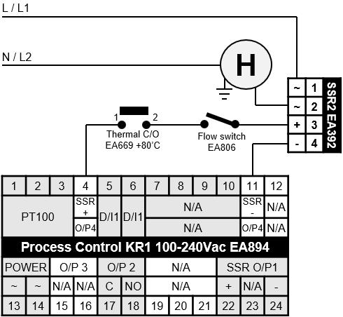
2 The controller (EA849 in this case) carries two solid state relay (SSR) outputs. The first is used for cooling and the second is used for heating.
3
Low voltage 12Vdc comes from both cooling and heating outputs to their own SSRs. Pictured right, is terminals 4+11 connected to terminals 3 and 4 of the SSR EA392.
4 In series with the positive side of the circuit are a thermal cutout, normally mounted on the tank within which the heaters are installed, and a flow switch.
5 Either of the devices opening in fault state result in the SSR failing to close. Heater(s) are installed with the SSR contacts in series with the live(s) that feed the heater(s), preventing it running.
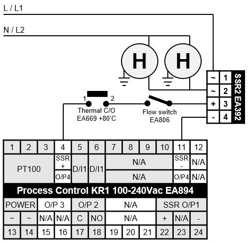
In the above, the low voltage control SSR has a contact side capable of supporting the current pulled by two heaters in parallel.
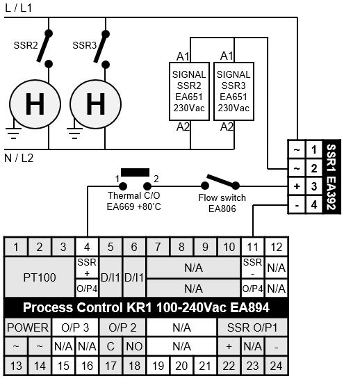
In the above, the low voltage control SSR drives two more SSRs whose contacts drive the heaters. This allows the controllers to drive more, higher-powered heaters.
Applied Thermal Control Ltd
39 Hayhill Industrial Estate
Barrow-upon-Soar, Loughborough
LE12 8LD, United Kingdom
+44 (0) 1530 839 998
Service@thermalexchange.co.uk
Support@app-therm.com
Date 30/NOV/2021
Author(s) MJH
Serial communication protocol ModBUS® for KM/KR/KX (KM1-KM3-KR1KR3-KX1-KX3)
this document is related to the firmware version 4.2
29 / 68 Revision 1
Tecnologic uses ModBUS® RTU communication protocol. It is a royalty free protocol and it is easy to implement.
For ModBus RTU a vast literature is available also in internet. The ModBus protocol represent all data in hexadecimal format.
All communication string finish with a check sum type CRC (cyclic redundancy check). Every devices in a line must have different address.
The protocol allows one master only and up to 255 slaves
Only Master unit can start the transmission by sending the address of the unit and the command to execute. Only the unit having the same address will answer to the master.
The transmission characteristics are usually programmable:
Device address: From 1 to 255.
Baud rate: bit per second. byte format:
– 1 start bit;
– 8 data bits;
– 2 final bits composed as follows: 1 parity bit (even or odd); 1 stop bit; or no parity bit; 2 stop bits.
The K30 allows to configure:
– address (1 – 254);
– Baud rate (1200 – 2400 – 9600 – 19200 – 38400).
The byte format is fixed: 8 bits without parity and 1 stop bit.
This document is intended to describe the K30 controllers using the MODBUS protocol in their communication capability and is mainly directed to technicians, system integrators and software developers.
Kube series controllers are provided with a RS485 serial communication interface, insulated so that any problem arising from ground potential is removed.
While at rest, the instruments are in a receive condition and are revert to transmission after a correct message has been decoded that matches the configured address.
The instruments are equipped with 2 terminals named A and B.
The connection between Kube s has to be carried on in parallel, i.e. all A terminals have to be connected between them so as B terminals. A termination resistor of 120 is required to maintain the quiescent condition on the line.
Adopted baud rates range 1200... 38400 baud, that is very satisfactory for application performances, yet very slow for RS485 interface. This fact allows the wiring of the line with a medium quality twisted pair cable: total capacity of the line should not exceed 200 nF. The line can be up to 1000 meters in length.
TheprotocoladoptedbyK30isasubsetofthewidelyusedMODBUSRTU(JBUS,AEGSchneiderAutomation,Inc.registeredtrademark) protocol, so that connections are easy for many commercial PLCs and supervisory programs. For users needing to develop their own communication software, all information is available as well as implementation hints. The MODBUS RTU (JBUS) communication functions implemented in Kube series are:
Function 3
Read n register;
Function 6 Preset one register;
Function 16 Preset multiple registers.
These functions allow the supervisory program to read and modify any data of the controller. The communication is based on messages sent by the master station (host) to the slave stations (K 30) and vice versa. The slave station that recognizes the message as sent to it, analyses the content and, if it is formally and semantically correct, generates a reply message directed back to the master.
The communication process involves five types of messages:
From master to slave
Function 3: read n registers request
Function 6: preset one register request
Function 16: preset multiple registers request
Every a message contains four fields:
From slave to master
Function 3: read n registers reply
Function 6: preset one register reply
Function 16: preset multiple registers reply
Exception reply (as reply to all functions in abnormal conditions)
Slave address (from 1 to 255): MODBUS RTU (JBUS) reserves address 0 for broadcasting messages and it is implemented in theKube series;
Function code: contains 3, 6 or 16 for specified functions;
Information field: contains data like word addresses and word values as required by function in use;
Control word: a cyclic redundancy check (CRC) performed with particular rules for CRC16. The characteristics of the asynchronous transmission are 8 bits, no parity, one stop bit.
This function code is used by the master to read a group of sequential registers present in the slave.
address (MSB = Most Significant Byte)
register address (LSB = less Significant Byte)
(LSB)
(MSB)
In the “Data(s)” field the values of the requested registers are presented in word format [2 byte] : the first byte represent the MSB (Most Significant Byte) while the second byte represent the LSB (Less Significant Byte). This mode will be the same for all requested locations. Example:
The master requires to the address 1 the value of the locations 25 and 26 (0x19 and 0x1A).
Master request Data
Slave address 01
Byte (Hex)
Function code ( 3 = read ) 03
First register address (MSB) 00
First register address (LSB) 19
Number of requested registers (MSB) 00
Number of requested registers (LSB) 02
CRC-16 (LSB) 15
CRC-16 (MSB) CC
The slave replay means:
The value of the location 25 = 10 (0x000A hexadecimal)
The value of the location 26 = 20 (0x0014 hexadecimal)
Slave reply Data Byte (Hex)
Slave address 01
Function code (3 = read) 03
Byte number 04
Value of the first register (MSB) 00
Value of the first register (LSB) 0A
Value of the second register (MSB) 00
Value of the second register (LSB) 14 CRC-16 (LSB) DA CRC-16 (MSB) 3E
Master request Data Byte (Hex)
Slave address 01
Function code ( 6 ) 06
Register address (MSB) 03
Register address (LSB) 02
Value to write (MSB) 00
Value to write (LSB) 0A
CRC-16 (MSB) A8
CRC-16 (LSB) 49 Slave reply Data
Example:
(Hex) Slave address (1-255) 1 Function code ( 6 ) 1
address (MSB) 1
address (LSB) 1
(MSB) 1
(LSB) 1 CRC-16 (MSB) 1 CRC-16 (LSB) 1
The master unit asks to the slave 1 to write in the memory location 770 (0x302) the value 10 (0x0A).
Master request Data Byte (Hex)
Slave address 01
Function code ( 6 ) 06
Register address (MSB) 03
Register address (LSB) 02
Value to write (MSB) 00
Value to write (LSB) 0A
CRC-16 (MSB) A8
CRC-16 (LSB) 49
Slave reply Data
Slave address 01
Byte (Hex)
Function code ( 6 ) 06 Register address (MSB) 03 Register address (LSB) 02 Written value (MSB) 00
Written value (LSB) 0A
CRC-16 (MSB) A8
CRC-16 (LSB) 49
3.3 Function code 16: preset multiple registers (maximum 16registers)
This function code allows to preset 16 registers at a time.
Master request
Slave address (1-254)
Example:
(LSB)
(MSB)
(LSB) 1
(LSB) 1
(MSB)
The master unit requires to the slave 1 to write in the registers 10314 (0x284A) and 10315 (0x284B) the values 100 (0x64) and 200 (oxC8)
code ( 16 )
register address (MSB)
register address (LSB) 4A Number of requested registers (MSB) 00 Number of requested registers (LSB) 02
(MSB)
register address (MSB)
register address (LSB) 4A Number of written registers (MSB) 00 Number of written registers (LSB) 02
CRC-16 (LSB) 69 CRC-16 (MSB) BE
(LSB)
(MSB)
Kube instruments reply with an exception when the request is formally correct, but cannot be satisfied standing particular situations; the reply contains a code indicating the cause of the missing regular reply, the frame is:
Kube series adopts a subset of MODBUS RTU (JBUS) exception code: – Unknown function code 1
– Invalid memory address 2 – Invalid data field 3 – Controller not ready 6
CRC is a check word that permits to verify the integrity of a message. Every message, sent or received, has in the two last characters the CRC check word.
After receiving a request, the controller checks the validity of the received message comparing the received CRC with the calculated one. When a reply is ready the controller calculates the CRC word and adds two characters to the prepared message. CRC calculation is performed on every character of the message, excluding the last two.
Being MODBUS RTU (JBUS) compatible, Kube series controllers adopt an identical algorithm for CRC calculation, sketched in following diagram:
CRC = FFFF hex

next character
CRC = CRC exor char n = 0


Shift on the left of CRC in thecarry
Carry = 1?

CRC = CRC exor POLY



N < 8?



Other character? The CRC calculation is finished n = n + 1
The polinomial adopted by MODBUS RTU (JBUS) is 1010 0000 0000 0001. note: The first transmitted character of the CRC word is the least significant between calculated bytes.
Tecnologic S.r.l.
Follows a subroutine made with “C” able to calculate the CTC-16. /* crc_16 calcolo del crc_16
Parametri di ingresso:
buffer: stringa di caratteri di cui calcolare il CRC-16 length: numero di bytes della stringa
Questa funzione ritorna il valore di CRC-16 */
unsigned int crc_16 (unsigned char *buffer, unsigned int length)
{ unsigned int i, j, temp_bit, temp_int, crc; crc = 0xFFFF;
for (i = 0; i < length; i++ ){ temp_int = (unsigned char) *buffer++; crc ^= temp_int;
for ( j = 0; j < 8; j++ ) { temp_bit = crc & 0x0001; crc >>= 1; if ( temp_bit != 0 ) crc ^= 0xA001; } } return (crc);
} note: All numerical values in the format 0x. are expressed in hexadecimal format.
This section contains information about data exchanged with Kube series controllers concerning numerical and not numerical data, with their formats and limits.
All exchanged data are in the form of 16 bit words.
Two types of data are distinguished: numerical and symbolic (or not numerical).
Numerical data represents the value of a quantity (e.g. the measured variable, the set point).
Symbolic data represents a particular value in a set of values (e.g. the thermocouple type in the set of available ones: J, K, S ...).
Both types are coded as integers number : signed numbers for numerical and unsigned numbers for symbolic. A numerical data, coded as an integer, is coupled with appropriate number of decimal digits to represent a quantity with the same engineering units adopted aboard the instrument.
Numerical data are in fixed point representation; however we make a distinction between two kinds of data:
The first kind has determined and unmodifiable decimal point position;
The second has programmable decimal point position (dP parameter).
All readable and writable data appear to be allocated as 16 bit words in the memory of the instrument. The memory map has three zones:
Variables,
Parameters,
Instrument identification code.
Following parameters explore the characteristics of each zone.
In this zone there is a collection of main Kube controller variables, it is a group of frequently computed or updated data residing in volatile memory.
a) During parameter modification by push-button, the serial interface continue to operate without any “limit” (you can see by serial link the value of all parameters and you can set it also).
B) When you write a value in a location the instrument will operate as follows:
B.1) If you write a value within parameter range, the instrument will accept it; the new value will be memorized and the instrument will send back the standard answer.
B.2) If you try to write a value OUT of parameter range, the instrument will refuse the new value; the new value will NOT be memorized and the instrument will send an exception message to the master. These are available data:
All Kube instruments use only words: initial address Final address Meaning hex dec hex dec
1 1 1D 29
200 512 250 592
Group of variables common to all new Ascon Tecnologic’s instruments: numeric values calculated and dynamically updated. Available in read and write operations
Group of variables compatible with the old Ascon Tecnologic’s instruments (before Kube series): numeric values calculated and dynamically updated. Available in read and write operations
280 640 31B 795 Configuration parameters: Numeric and symbolic values. Available in read and write operations
800 2048 82C 2092 Instrument identification parameters
2800 10240 289B 10395 Repetition of the configuration parameters: Numeric and symbolic values. Available in read and write operations
1A 1 1
pV: Measured value
note: When a measuring error is detected the instrument send:
• 10000 = Under range
• 10000 = Over range • 10001 = Overflow of the A/D converter • 10003 = Variable not available
2A 2 2 number of decimal figures of the measured value
3A 3 3 operative set point (value)
4A 4 4 power output
Range: -100.00 ÷ 100.00 (%)
note: This parameter is ever writeable but it will be active only when the instrument operate in Manual mode.
5A 5 5 active set point selection 0 = SP 1 = SP 2 2 = SP 3 3 = SP 4
6A 6 6 Sp Range: SPLL ÷ SPLH
7A 7 7 Sp 2 Range: SPLL ÷ SPLH
8
9 9 Sp 4
alarms status
bit 0 = Alarm 1 status
bit 1 = Alarm 2 status
bit 2 = Alarm 3 status
bit 3 ÷ 8 = Reserved
10A A 10
bit 9 = LBA status
bit 10 = Power failure indicator
bit 11 = Generic error
bit 12 = Overload alarm
bit 13 ÷15 =Reserved
outputs status (physical outputs)
bit 0 = Output 1 status
bit 1 = Output 2 status
bit 3 = Output 3 status
11A B 11
bit 4 = Output 4 status
bit 5 = Output 5 status
bit 6÷15 = Reserved
When an output is driven by serial link, the relative bit will remain equal to 0.
12A C 12
instrument status
bit 0 = Automatic
bit 1 = manual
bit 2 = Standby
bit 3 = Remote Set point (temporary) used
bit 4 = Auto-tuning active
bit 5 = Self tuning active
bit 6 = Reserved
bit 7 = Timer running
bit 8 = Soft start running
bit 9 = Ramp for set point change (up or down) running
bit 10 = Delay at start up (od) running
bit 11 = Program running
bit 12 = Measure status (0 = OK while 1 = error). bit 13÷15 = Reserved
F 15
16A 10 16
Remote set point (temporary) (from serial link) Range: SPLL ÷ SPLH note: the remote set point is stored in RAM
identification code
0 ÷ 65535 note: The word is composed by two parts: - Low byte – Version of the parameter table - High byte – Version of the family protocol
22A 16 22
First temporary code for speed configuration
The code is composed by two distinct 4 digits subcodes:
aaBB where:
aa = Input type: 0 ÷25
BB = Control type and service functions 0 ÷ 21
note: 10000 = Temporary value not inserted
The programmed codes will be activated only after both have been correctly be programmed. The order has no importance.
Second temporary code for speed configuration
The code is composed by two distinct 4 digits subcodes:
CdEF where:
C = Alarm type 1 0 ÷ 9
d = Alarm type 2 0 ÷ 9
23A 17 23
E = Alarm type 3 0 ÷ 9
F = Enabling service functions 0 ÷ 4
note: 10000 = Temporary value not inserted
The programmed codes will be activated only after that both have been correctly programmed. The order has no importance.
24A 18 24
First final code for speed configuration
When programmed, the code is composed by two distinct 4 digits subcodes: aaBB where:
aa = Input type: 0 ÷25
BB = Control type and output functions 0 ÷ 21
If not programmed, the return value is -1 = Code not programmed.
Second temporary code for speed configuration
When programmed, the code is composed by two distinct 4 digits subcodes: CdEF where:
C = Alarm 1 type 0 ÷ 9
25A 19 25
d = Alarm 2 type 0 ÷ 9
E = Alarm 3 type 0 ÷ 9
F = Enabling service functions 0 ÷ 4
If not programmed, the return value is -1 = Code not programmed.
26A 1A 26 time to end of running program segment
Range: 0 ÷ 9959 (hh.mm or mm.ss)
note: When the program is not active, the return value is 0.
Manual autotuning start request pending for od or Soft start
27A 1B 27
Range: 0 = No pending request waiting for the execution; 1 = Pending request waiting for the execution
autotuning start request pending for setpoint change for od or Soft start
28A 1C 28
Range: 0 = No pending request waiting for the execution; 1 = Pending request waiting for the execution
29A 1D 29 Value to be retransmitted on the analogue output Range: Ao1L
5.2 group of variables compatible with the old Ascon Tecnologic’s instruments (before Kube series)
13B 0224 548
Status/remote control of the output 1
0 = OFF 1 = ON
note: This parameter is writeable when out 1 is “not used” by the controller (o1F output 1 function = nonE). This parameter is stored in RAM
Status/remote control of the output 2
14B 0225 549
0 = OFF 1 = ON
This parameter is writeable when out 2 is “not used” by the controller (o2F output 1 function = nonE). This parameter is stored in RAM
Status/remote control of the output 3
15B 0226 550
0 = OFF 1 = ON
note: This parameter is writeable when out 3 is “not used” by the controller (o3F output 1 function = nonE). This parameter is stored in RAM
16B 0227 551
Status/remote control of the output 4 0 = OFF 1 = ON note: This parameter is writeable when out 4 is “not used” by the controller (o4F output 1 function = nonE). This parameter is stored in RAM
= Wait (system)
= End (system)
program step in execution
0 = Program not active
1 = ramp step 1
2 = soak step 1
2 = ramp step 2
4 = soak step 2
5 = ramp step 3
6 = soak step 3
7 = ramp step 4
8 = soak step 4 9 = END
Remaining time to the timer end
Range: 0 ÷ 65535 (Hours when Tru=hh.mm, Minutes when Tru=mm.ss)
0 ÷ 9959 (tenth of seconds when Tru=SSS.d) note: When the timer is not active the return code is
25B 24A 586
Wattmeter:
The meaning of this parameter is defined by the CO.ty parametersetting.
CO.ty = 0ff 0
CO.ty = 1 Instantaneous power (kW);
CO.ty = 2 Consumed energy (kWh);
CO.ty = 3 Energy used during program execution (kWh);
CO.ty = 4/6
CO.ty = 5/7
CO.ty = 8/10
Total worked days;
Total worked hours;
Totalizer of control relay worked days;
CO.ty = 9/11 Totalizer of control relay worked hours.
28B
Model Code – Output 2 type
Range: 0x2D = ‘-’ - Not present 0x4D = ‘M’ – Servomotor command relay
5.4 parameters Setting: addresses form 280 hex (640 dec) and 2800 hex (10240 dec)
5.4.1 inp gRoUp - Main and auxiliary input configuration
0 = J = TC J,
1 = crAL = TC K,
2 = S = TC S,
3 = r = TC R,
4 = t = TC T,
5 = ir.J = IRS J,
6 = ir.cA = IRS K,
1 SEnS 280 2800 640 10240
Model C (Pt100, Pt1000)
Model E (Ptc, Ntc)
7 = Pt1 = RTD Pt100, 8 = Pt10 = RTD Pt1000,
9 = 0.60 = 0... 60 mV, 10 = 12.60 = 12... 60 mV, 11 = 0.20 = 0... 20 mA,
12 = 4.20 = 4... 20 mA,
13 = 0.5 = 0... 5 V, 14 = 1.5 = 1... 5 V,
15 = 0.10 = 0... 10V, 16 = 2.10 = 2... 10V
0 = J = TC J, 1 = c rAL = TC K, 2 = S = TC S, 3 = r = TC R, 4 = t = TC T, 5 = ir.J = IRS J, 6 = ir.cA = IRS K,
7 = Ptc = TC KTY81-121, 8 = ntc = NTC 103-AT2, 9 = 0.60 = 0... 60 mV, 10 = 12.60 = 12... 60 mV, 11 = 0.20 = 0... 20 mA, 12 = 4.20 = 4... 20 mA, 13 = 0.5 = 0... 5 V, 14 = 1.5 = 1... 5 V, 15 = 0.10 = 0... 10V, 16 = 2.10 = 2... 10V
0 = on = Output used as PWS forTX, 1 = out4 = Output 4 (digital output 4), 2 = dG2c = Digital input 2 driven by contact, 3 = dG2U = Digital input 2 driven byvoltage
10 diF1
11 diF2
289 2809 649 10249 Digital Input 1 function
28A 280A 650 10250 Digital Input 2 function
5.4.2 out group
Digital Inputs Action note: The addresses related to this parameter are inserted after the last parameter set [157] tSd2
10251 Output 1 type (when Out 1 is an analogue output KM3 only)
0 = oFF = Not used, 1 = Alarm reset, 2 = Alarm acknowledge (ACK), 3 = Hold of the measured value, 4 = Standby mode, 5 = Manual mode, 6 = HEAt with SP1 and CooL with SP2, 7 = Timer RUN/Hold/Reset, 8 = Timer Run, 9 = Timer Reset, 10 = Timer Run/Hold, 11 = Timer Run/Reset, 12 = Timer Run/Reset with lock, 13 = Program Start, 14 = Program Reset, 15 = Program Hold, 16 = Program Run/Hold, 17 = Program Run/Reset, 18 = Sequential SP selection, 19 = SP1 - SP2 selection, 20 = SP1... SP4 binary selection, 21 = Digital inputs in parallel to and keys


0 = oFF = Not used, 1 = Alarm reset, 2 = Alarm acknowledge (ACK), 3 = Hold of the measured value, 4 = Stand by mode, 5 = Manual mode, 6 = HEAt with SP1 and CooL with SP2, 7 = Timer RUN/Hold/Reset, 8 = Timer Run, 9 = Timer Reset, 10 = Timer Run/Hold, 11 = Timer Run/Reset, 12 = Timer Run/Reset with lock, 13 = Program Start, 14 = Program Reset, 15 = Program Hold, 16 = Program Run/Hold, 17 = Program Run/Reset, 18 = Sequential SP selection, 19 = SP1 - SP2 selection, 20 = SP1... SP4 binary selection, 21 = Digital inputs in parallel to and keys


0 = DI1 direct action, DI2 direct action; 1 = DI1 reverse action, DI2 directaction; 2 = DI1 direct action, DI2 reverseaction; 3 = DI1 reverse action, DI2 reverse action.
0 = 0-20 = 0-20 mA 1 = 4-20 = 4-20 mA 2 = 0-10 = 0-10V 3 = 2-10 = 2-10V
Out 1 function
(when Out 1 is a linear output)
14 o1F 28C 280C 652 10252
Out 1 function
(when Out1 is a digital output)
0 = NonE = Output not used
1 = H.rEG = Heating output
2 = c.rEG = Cooling output
3 = r.inP = Measure retransmission
4 = r.Err = Error (sp - PV) retransmission
5 = r.SP = Set point retransmission
6 = r.SEr = Serial value retransmission
0 = NonE = Output not used
1 = H.rEG = Heating output
2 = c.rEG = Cooling output
3 = AL = Alarm output
4 = t.out = Timer output
5 = t.HoF = Timer out -OFF in hold
6 = P.End= Program end indicator
7 = P.HLd = Program hold indicator
8 = P.uit = Program wait indicator
9 = P.run= Program run indicator
10 = P.Et1 = Program Event 1
11 = P.Et2 = Program Event 2
12 = or.bo = Out-of-range or burn out indicator
13 = P.FAL = Power failure indicator
14 = bo.PF = Out-of-range, burn out and Power failure indicator
15 = St.bY = Stand by status indicator
16 = diF.1 = The output repeats the digital input 1 status
17 = diF.2 = The output repeats the digital input 2 status
18 = on = Out 1 always ON
0...
28 AL1t
29A 281A 666 10266 Alarm 1 type
0 = nonE = Alarm not used
1 = LoAb = Absolute low alarm
2 = HiAb = Absolute high alarm
3 = LHAo = Windows alarm in alarm outside the windows
4 = LHAI = Windows alarm in alarm inside the windows
5 = SE.br = Sensor Break
6 = LodE = Deviation low alarm (relative)
7 = HidE = Deviation high alarm (relative)
8 = LHdo = Relative band alarm in alarm out of the band
9 = LHdi = Relative band alarm in alarm inside the band
29 Ab1 29B 281B 667 10267 Alarm 1 function 0... 15
668 10268 - For High and low alarms, it is the low limit of the AL1 threshold; - For band alarm, it is low alarm threshold
669 10269 - For High and low alarms, it is the high limit of the AL1 threshold; - For band alarm, it is high alarm threshold
+1 = Not active at power up
+2 = Latched alarm (manual reset)
+4 = Acknowledgeable alarm
+8 = Relative alarm not active at set point change
Alarm 1 enabling during Stand-by mode and out of range conditions
0 = Alarm 1 disabled during Stand by and out of range
1 = Alarm 1 enabled in stand by mode
2 = Alarm 1 enabled in out of range condition
3 = Alarm 1 enabled in stand by mode and in over range condition
High and low alarms, it is the low limit of the AL2 threshold; - For band alarm, it is low alarm threshold
0 = nonE = Alarm not used
1 = LoAb = Absolute low alarm
2 = HiAb = Absolute high alarm
3 = LHAo = Windows alarm in alarm outside the windows
4 = LHAI = Windows alarm in alarm inside the windows
5 = SE.br = Sensor Break
6 = LodE = Deviation low alarm (relative)
7 = HidE = Deviation high alarm (relative)
8 = LHdo = Relative band alarm in alarm out of the band
9 = LHdi = Relative band alarm in alarm inside the band
15
+1 = Not active at power up
+2 = Latched alarm (manual reset)
+4 = Acknowledgeable alarm
+8 = Relative alarm not active at set point change
AL2o 2A9
681 10281 Alarm 2 enabling during Stand-by mode and out of range conditions
AL3t 2AA 282A 682 10282 Alarm 3 type
0 = Alarm 2 disabled during Stand by and out of range
1 = Alarm 2 enabled in standby mode
2 = Alarm 2 enabled in out of range condition
3 = Alarm 2 enabled in standby mode and in over range condition
0 = nonE = Alarm not used
1 = LoAb = Absolute low alarm
2 = HiAb = Absolute high alarm
3 = LHAo = Windows alarm in alarm outside the windows
4 = LHAI = Windows alarm in alarm inside the windows
5 = SE.br = Sensor Break
6 = LodE = Deviation low alarm (relative)
7 = HidE = Deviation high alarm (relative)
8 = LHdo = Relative band alarm in alarm out of the band
9 = LHdi = Relative band alarm in alarm inside the band
15 +1 = Not active at power up +2 = Latched alarm (manual reset) +4 = Acknowledgeable alarm +8 = Relative alarm not active at set point change
5.4.7 rEg group - Control parameters
56 cont 2B6 2836 694 10294 Control type
57 Auto 2B7 2837 695 10295 Autotuning selection
0 = Pid = PID (heat and/or)
1 = On.FA = ON/OFF asymmetric hysteresis
2 = On.FS = ON/OFF symmetric hysteresis
3 = nr = Heat/Cool ON/OFF control with neutral zone
4 = 3Pt = Servomotor control (available onlywhen output2andoutput3havebeenorderedas“M”)
-4 = Oscillating auto-tune with automatic restart at power up and after all point change
-3 = Oscillating auto-tune with manual start
-2 = Oscillating -tune with automatic start at the first power up only
-1 = Oscillating auto-tune with automatic restart at every power up
0 = Notused
1 = Fast auto tuning with automatic restart at every power up
2 = Fast auto-tune with automatic start the first power up only
3 = FAST auto-tune with manual start
4 = FAST auto-tune with automatic restart at power up and after a set point change
5 = Evo-tune with automatic restart at every power up
6 = Evo-tune with automaticstart the firstpowerup only
7 = Evo-tune with manualstart
8 = Evo-tune with automatic restart at power up and after a set point change
0 = RSP= Thevaluecomingfromseriallinkisusedas remote set point
1 = trin = The value will be added to the local set point selected by A.SP and the sum becomes the operative set point 2 = PErc = The value will be scaled on the input range and this value will be used as remote SP
0 = NonE = Timer not used 1 = i.d.A = Delayed start timer 2 = i.uP.d = Delayed start at power up 3 = i.d.d = Feed-through timer 4 = i.P.L = Asymmetrical oscillator with start OFF 5 = i.L.P = Asymmetrical oscillator with start ON
When tr.u = 0: 1... 9959(hh.mm) When tr.u = 1: 1... 9959(mm.ss)
When tr.u = 0: From 0 (oFF) to 9959 (inF) (hh.mm) When tr.u = 1: From 0 (oFF) to 9959 (inF) (mm.ss)
When tr.u = 2: From 0000 (oFF) to 9959 (inF) (tenth of seconds) 1
0 = rES = Timer reset 1 = run = Timer run
5.4.10 pRg group - programmer function parameters
93 Pr.F 2DB 285B 731 10331 Program action at power up
95 Pr.E 2DD 285D 733 10333 Instrument behavior at the end of the program execution
0 = nonE = Programmer not used 1 = S.uP.d = Start at power up with a first step in stand-by 2 = S.uP.S = Start at power up
3 = u.diG = Start at Run command detection only 4 = u.dG.d = Start at Run command with a first step in stand-by
= cnt = Continue
= A.SP = Go to the set point selected by A.SP
= St.by = Go to stand-by mode
121 uSrb
122 diSP
2F7
2877
759 10359 a button function during RUN TIME
0 = nonE = No function
1 = tunE = Auto-tune/self-tune enabling. A single press (longer than 1 second) starts the auto-tune
2 = oPLo = Manual mode.
The first pressure puts the instrument in manual mode (oPLo) while a second one puts the instrument in Auto mode
3 = AAc = Alarm reset
4 = ASi = Alarm acknowledge
5 = chSP = Sequential set point selection
6 = St.by = Stand by mode. The first press puts the instrument in stand by mode while a second one puts the instrument in Auto mode.
7 = Str.t = Timer run/hold/reset
8 = P.run = Program run
9 = P.rES = Program reset
10 = P.r.H.r = Program run/hold/reset
0 = nonE = Standard display
1 = Pou = Power output
2 = SPF = Final set point
3 = Spo = Operative set point
4 = AL1 = Alarm 1 threshold
5 = AL2 = Alarm 2 threshold
6 = AL3 = Alarm 3 threshold
7 = Pr.tu = - During a soak, the instrument shows the soak elapsed time;
- - During aramp thedisplayshowstheoperativesetpoint. Attheendoftheprogramexecution,theinstrumentwillshow “P.End”messagesalternatelywiththemeasuredvalue.
- - When no program is running, the instrument shows the standard display
8 = Pr.td = - During a soak, the instrument shows the soak remaining time (count down).
2F8
2878 760 10360 Display management
- - During a ramp the display shows the operative set point. At the end of the program execution, the instrument shows “ n ” messages alternately with the measured value
- - When no program is running, the instrument showsthe standard display.
9 = P.t.tu = When the programmer is running, the display shows the total elapsed time. At the end of the program execution, the instrument shows “t. n ” messages alternately with the measured value
10 = P.t.td = When the programmer is running, the display shows the total remaining time (count down). At the end of the program execution, the instrument shows “ . n ” messages alternately with the measured value.
11 = ti.uP = When the timer is running, the display shows the timer counting up. At the end of the counting, the instrument shows “t. n ” messages alternately with the measured value
12 = ti.du = Whenthetimerisrunning,thedisplayshowsthetimercounting down At the end of the counting, the instrument shows “t n ” messages alternately with the measured value.
13 = PErc = Percent of the power output used during soft start (when the soft start time is equal to infinite, the limit is ever active and it can be used also when ON/OFF control is selected)
0 = The display colour changes to point out the actual deviation (PV - SP)
1 = Display red (fix)
2 = Display green (fix)
3 = Display orange (fix)
126 fiLd 2FC
287C 764 10364 Filter on the displayed value 0 = oFF (filter disabled)... 100
0 = nonE = Bar graph not lit
1 = Pou = PID Output power (single action: 0... 100%, double action: -100... +100%)
2 = Po.h = Energy Used (kWh)
127 Bg.F
128 dSPu
129 oPr.E
2FD
287D 765 10365 Bar graph Function
2FE
287E 766 10366 Instrument status at power ON
767 10367 Operative modes enabling
oPEr 300 2880 768 10368 Operative mode
3 = Pr.tu = Elapsed time of the program in execution
4 = Pr.td = Time to end of the program in execution
5 = Pr.tS = Time to end of the program segment in execution
6 = ti.uP = Elapsed time of timer (T1 and T2)
7 = ti.du = Time to end of timer (T1 andT2)
8 = r.iSP = Time to preventive maintenance
0 = AS.Pr = Starts in the same way it was prior to the power down
1 = Auto = Starts in Auto mode
2 = oP.0 = Starts in manual mode with a power output equal to zero
3 = St.bY = Starts in stand-by mode
0 = ALL = All modes will be selectable by the next parameter
1 = Au.oP = Auto and manual (OPLO) mode only will be selectable by the next parameter
2 = Au.Sb=AutoandStand-bymodesonlywillbeselectablebythenext parameter
=
0 = nonE = Retransmission not used (the instrument is a slave) 1 = rSP = The instrument becomes a Master and retransmits the operative set point
2 = PErc = The instrument become a Master and it retransmits the power output
0 = oFF = Not
(kW)
2 = Power consumption (kW/h)
3 = Energy used during program execution. This measure starts from zero when a program runs end stops at the end of the program. A new program execution willreset the value
4 = Total worked days with threshold. It is the number of hours that the instrument is turned ON divided for 24
5 = Total worked hours with threshold. It is the number of hours that the instrument is turned ON
5.4.14 Cal group - User calibration parameters


All rights reserved. No parts of this publication maybe reproduced, in any form, without Ascon Tecnologic S.r.l. written permission.
Every care has been taken preparing this manual; the document has been carefully reviewed for technical accuracy. In the event that technical or typographical errors exist Ascon Tecnologic S.r.l. reserves the right to make changes without any notice.
In no event shall Ascon Tecnologic S.r.l. be liable for any damages arising out of or related to this document or the information contained in it.
If errors are suspected, please contact Ascon Tecnologic S.r.l. at the above address.
Ascon Tecnologic S.r.l. Via Indipendenza, 56 27029 Vigevano (PV) Italia
Tel. ++39/0381/69871
Fax ++39/0381/698730
www.ascontecnologic.com support@ascontecnologic.com info@ascontecnologic.com
+44 (0) 1530 839 998
Service@thermalexchange.co.uk
Support@app-therm.com
Date 10/JUN/2022 Author(s) MJH
SA00012 provides access to switches to describe certain system conditions. The switches do not have voltage across them, they are ‘volt-free’ – the end-user or system builder can apply their own control system voltages. This approach is less complex than communications protocols such as RS485, but more limited in function.
1
Volt-free contacts (sometimes called volt-free switches) are electrical circuits that open or close depending on the state of relays driven by hardware conditions elsewhere in the product. Temperature (pins 8&9) is captured from a controller output – this parameter can be easily adjusted, but factory setting is to go open-circuit within +/-10°C of setpoint. Flow (pins 6&9) is captured from either a flow switch or a controller reading pulses from a flow meter. Flow switches may be fixed or adjustable but will always have hysteresis built-in. Flow sensors can have a single switching point. Circuit becomes unmade on low-flow. Level (pins 4&9) is captured from a reed switch in the tank. By default, this signal is open-circuit once the fluid level is too low and the pump has stopped. All-OK (pins 2&9) combines the three signals onto a single pin pairing, sharing the same open-circuit=not OK logic.
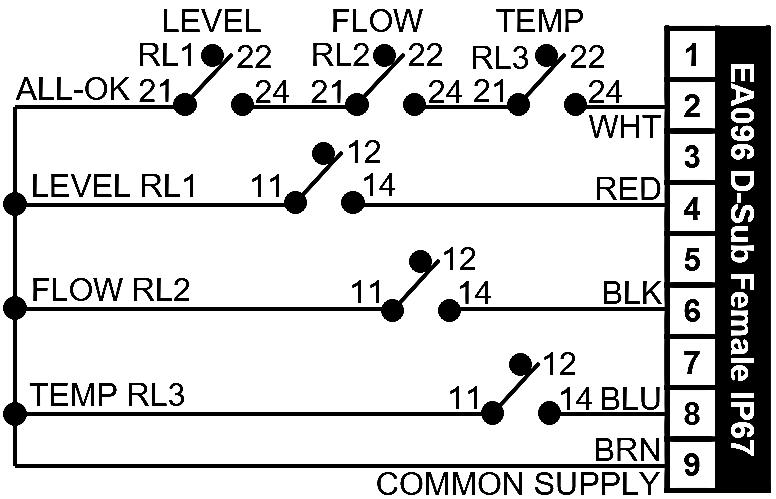
Dependent on your product type, signals will either be accessible via a standard two-row 9-pin D subminiature connector (see below left) OR direct connection to terminal blocks (see below right). Where a D connector is provided, the female gender (ATC PN EA096) is supplied in all cases. If male pins are required, we recommend using a male-to-male gender-changer connector (ATC PN EA853). Pin numbers are clearly marked on the molding. The connector is rated to IP67.
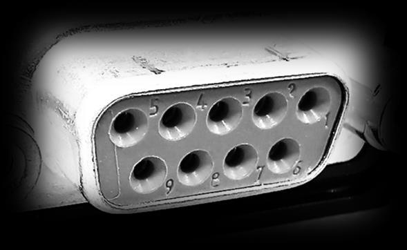
Relays used in this standard option pack have the following ratings;
AC-1 (AC resistive loads)
230Vac@8A (D-connector limited)
3
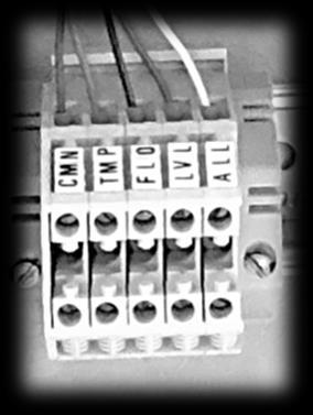
AC-15 (AC electromagnetic loads) 230Vac@3A (D-connector limited)
DC-13 (DC electromagnetic loads) 24Vdc@2A
39
Service@thermalexchange.co.uk
Support@app-therm.com
Date 1/MAR/2021 Author(s) MJH
This guide may apply to your product if your airblast A-series product was bought with standard option SA00024. Temperature stability is enhanced by regulating the amount of air passing through the heat exchanger. The fan speed is managed by a PID controller, as opposed to continuous running or on-off control.
1 The controller is equipped with an analogue output to interface with the fan’s 0-10Vdc control input.
2 The fan is an ‘EC’ type whereby mains voltage is converted to DC to drive the a DC fan motor.
3 The controller sensor input informs the PID algorithm and the RPM is increased if temperature is too high.
4 Upon startup, it’s not uncommon to see 3-5 swings about the setpoint while the system stabilizes.
5 For troubleshooting purposes, the scale of 0-10Vdc can be considered 0-100% fan speed.
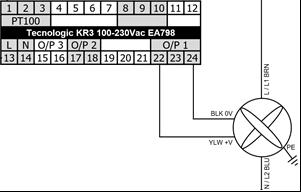
6 This approach enables stability of ≤0.5°C around setpoint. The longer the system is allowed to stabilize, the better the stability should become. A stable load and stable ambient are necessary to achieve this value.
7 To improve stability, review Annex E documentation for your product to see PID tuning options.
Service@thermalexchange.co.uk
Support@app-therm.com
This guide may apply to your machine if you use water as a process fluid and plan to site the product in an environment where it will see sub-zero temperatures. Any other working fluids with different freezing temperatures can be accommodated by adjusting the thermostat.
1
The frost protection device is a single pole double throw electrical switch with capillary-tube connected sensing bulb. The bulb is mounted typically on an external facing part of the unit to ensure it is exposed to ambient temperature and not a warm machine enclosure. Image right shows the capillary installed against the base stiffener of the W32/W40 enclosure.
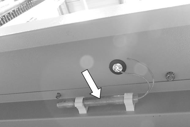
2
3
In the case where water is used, the bulb will be set to trigger when the ambient reaches +8°C. The switch is wired in such a way that the pump turns on, whether the chiller is set to run process or not. The additional heat from the pump motor is enough to prevent freezing water.
On rising ambient temperatures, the switch automatically moves back to prevent the pump running when process stop is selected.
In image right, point 1 shows the tripping point. A needle will move up and down the scale when adjusting screw marked at point 2. Take care not to take the needle beyond the scale. The differential scale (point 3) controls the hysteresis of the switch. Adjust with the screw at point 4.
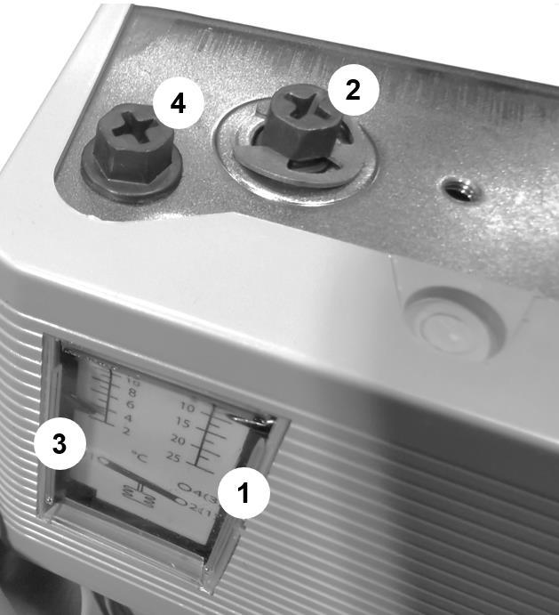
+44 (0) 1530 839 998
Service@thermalexchange.co.uk
Support@app-therm.com
Date 14/JUN/2022 Author(s) MJH
This guide may apply to your product if you purchased standard option SA00051. Chillers/coolers with automatic restart interlock systems can be fitted with relay contacts in that allow a remote supply of 24Vdc to switch the relay coil, satisfy the interlock chain, and start process. Unless specifically requested, the end user/OEM must generate the 24Vdc supply. It may be the case that there is a 24Vdc PSU in the product already – the standard option ensures satisfactory operation by avoiding overloading the PSU.
1
2
W-series and >XF050 units use terminal blocks to provide access for the end user to provide 24Vdc remote stop-start voltage.
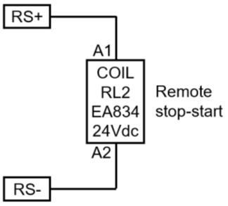
All other units use D connectors to apply voltage. The pin out to the right is only representative and your unit’s pin numbers for voltage supply may differ. Consult the wiring schematic for details.
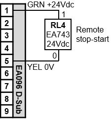
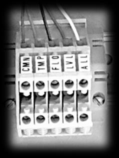
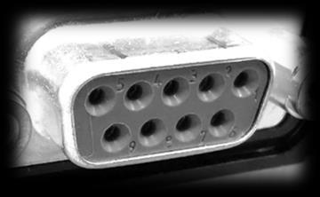
Recommended spares include all rotating machinery (i.e. motors, fans), all sacrificial elements (i.e.
and parts that users interact with (dials, fittings). Pricing is available from sales@app-therm.com.
Conforming to Directive 1907/2006/EC
SECTION 1: IDENTIFICATION OF THE SUBSTANCE/MIXTURE AND OF THE COMPANY/UNDERTAKING
1.1. Product Name Hexid A4
1.2. Supplier
Applied Thermal Control Limited 39 Hayhill Industrial Estate, Barrow upon Soar, Leicestershire, LE12 8LD. United Kingdom. www.app-therm.com
1.3. Telephone Number +44(0)1530 839998
1.4. Email sales@app-therm.com
1.5. Emergency Telephone Number +44(0)1530 839998
1.6. Intended/Recommended Use Heat Transfer Fluid
2.1. Classification of the substance or mixture
The product is not classified as dangerous according to Regulation (EC) No. 1272/2008. This mixture is not classified as dangerous according to Directive 1999/45/EC.
3.1. Chemical Nature Water (CAS 7732-18-5), not classified. Propylene glycol (CAS 57-55-6) (REACH 01-2119456809-23) (EINECS 200-338-0) not classified. Fluorescein (trace) and biocide (trace) not classified.
3.2. Food Grade
General advise No special precautions required. Treat symptomatically.
4.1 Eye Contact
Rinse thoroughly with plenty of water, also under the eyelids. Remove contact lenses after a few minutes and continue rinsing. If symptoms persist, call a physician.
4.2. Skin Contact Wash off immediately with plenty of water. If skin irritation persists, call a physician.
4.3. Inhalation
4.4. Ingestion
Remove to fresh air. If symptoms persist, call a physician.
Rinse mouth with water. Never give anything by mouth to an unconscious person. If symptoms persist, call a physician.
5.1. Extinguishing media
Use extinguishing measures that are appropriate to local circumstances and the surrounding environment. Water spray, foam, dry powder or CO2. Alcohol-resistant foam
5.2 Unsuitable extinguishing Media
High volume water jet. Do not use a solid water stream as it may scatter and spread fire.
5.3 Specific hazards during firefighting
In fire conditions, toxic decomposition products may be formed (see also section 10). In combustion, emits fumes, smoke, carbon dioxide (CO2) and carbon monoxide (CO). Heating will cause a pressure rise - with severe risk of bursting and explosion, Violent steam generation or eruption may occur upon application of direct water to hot liquids.
5.4. Advice for firefighters
In the event of fire, wear self-contained breathing apparatus. Wear personal protective equipment. Promptly isolate the scene by removing all persons from the vicinity of the incident if there is a fire. Keep containers cool by spraying with water if exposed to fire. Collect contaminated fire extinguishing water separately. This must not be discharged into drains. Burning fluids may be extinguished by dilution with water
Conforming to Directive 1907/2006/EC
6.1. Personal precautions
Use personal protective equipment. Avoid contact with skin and eyes. Keep unnecessary and unprotected personnel from entering the area.
6.2. Precaution to protect the environment
Do not flush into surface water or sanitary sewer system. Avoid subsoil penetration.
6.3 Clean-up procedures
Contain the spillage, soak up with non-combustible absorbent material, (e.g. sand, earth, diatomaceous earth, vermiculite) and transfer to a container for disposal according to local / national regulations (see section 13). Keep in suitable, closed containers for disposal. Dike the area of spill to prevent spreading and pump liquid to salvage tank. Treat recovered material as described in section 13 Disposal considerations.
7.1. Precautions for safe handling
Keep container tightly closed. Handle in accordance with good industrial hygiene and safety practice. Spills of these organic materials on hot fibrous insulations may lead to lowering of the auto-ignition temperatures possibly resulting in spontaneous combustion.
7.2. Conditions for safe storage
Keep only in the original container.
8.1. Control parameters
Component: Propane-1,2-diol CAS-No. 57-55-6
Other Occupational Exposure Limit Values EH40 WEL, Time Weighted Average (TWA):, Total vapour and particulates.150 ppm, 474 mg/m3
EH40 WEL, Time Weighted Average (TWA):, Particulate.10 mg/m3
ELV (IE), Time Weighted Average (TWA):, Total vapour and particulates.150 ppm, 470 mg/m3
ELV (IE), Time Weighted Average (TWA):, Particulate.10 mg/m3
8.2. Exposure controls/Appropriate engineering controls
Local exhaust. If this product contains ingredients with exposure limits, use process enclosures, local exhaust ventilation or other engineering controls to keep worker exposure below any recommended or statutory limits.
Personal protective equipment
Conforming to Directive 1907/2006/EC
Respiratory protection Suitable respiratory protective device Combination filter: A-P2
Filter Type Combined particulates and organic vapour type
Hand protection Category short time exposure Break through time> 10 min
Protective index Class 1 When prolonged exposure is expected: Break through time> 120 min
Protective index Class 4 Observe the information of the glove manufacturers on permeability. Protective gloves should be chosen according to Workplace Safety Assessment. Gloves recommended according to EN 374 (protection against chemicals).
Material Chemical resistant gloves made of butyl rubber or nitrile rubber category III according to EN 374.
SECTION 9: PHYSICAL AND CHEMICAL
SECTION
conditions of
No decomposition if stored and applied as directed. Stable under recommended storage conditions. Hygroscopic.
Hazardous polymerisation does not occur.
10.4. Conditions to avoid
Generation of gas from decomposition causes pressure in closed systems. Keep away from direct sunlight. Avoid high temperatures. Avoid temperatures exceeding the decomposition temperature. Avoid UV light.
10.5. Materials to avoid
Conforming to Directive 1907/2006/EC
Strong acids, Strong bases, Strong oxidizing agents.
10.6. Hazardous decomposition products
Aldehydes, Alcohols, Ether, Organic acids
SECTION 11: TOXICOLOGICAL INFORMATION
11.1. Toxicity Oral
LD50 : > 20000 mg/kg (rat) This product can present a small hazard if large quantities are swallowed.
11.2. Inhalation
LC50 : 6.15 mg/l (rat; 4 h; vapour) At ambient temperature the exposure to vapours is minimal due to a low volatility rate. Inhalation may cause irritation to the nose, throat, upper respiratory tract and lungs. No deaths occurred
11.3. Dermal
LD50 : > 20000 mg/kg (rabbit) Prolonged skin contact is unlikely to result in absorption of harmful amounts. Skin irritation by prolonged exposure is unlikely. Repeated contact may cause flaking and softening of skin.
11.4 Eyes
Slight irritation is possible. Direct contact with eyes may cause temporary irritation. Corneal injury is unlikely.
11.5. Sensitisation
Patch test on human volunteers did not demonstrate sensitisation properties.
11.6. CMR Carcinogenicity
Animal testing did not show any carcinogenic effects. Information given is based on data obtained from similar substances.
11.7 Mutagenicity
No data available
11.8. Reproductive toxicity
No data available.
11.9. Specific Target Organ Toxicity
Single exposure no data available Repeated exposure no data available
11.10 Other toxic properties
Repeated dose toxicity. In rare cases, repeated excessive exposure to propylene glycol may cause central nervous system effects. Aspiration hazard Due to its physical properties, the substance does probably not pose any aspiration hazard.
11.11. Other relevant toxicity information
Handle in accordance with good industrial hygiene and safety practice.
11.12 Experience with human exposure
Health injuries are not known or expected under normal use.
Conforming to Directive 1907/2006/EC
12.1 Acute toxicity
Fish - LC50 : 40613 mg/l (Oncorhynchus mykiss; 96 h) (static test)
Daphnia and other aquatic invertebrates - LC50 : 18340 mg/l (Ceriodaphnia Dubia (water flea); 48 h) (static test)
Algae - ErC50 : 19000 mg/l (Pseudokirchneriella subcapitata (green algae); 96 h) (Growth inhibition)
Bacteria - NOEC : > 20000 mg/l (Pseudomonas putida; 18 h)Chronic toxicity
Aquatic invertebrates - NOEC : 13020 mg/l (Ceriodaphnia Dubia (water flea); 7 d) (semi-static test)
12.2 Persistence and degradability
Biodegradability 81 % (anaerobic; Exposure Time: 28 d)(OECD 301 F)
Readily biodegradable 96 % (anaerobic; Exposure Time: 64 d)(OECD 306.)
12.3. Bioaccumulative potential
BCF - 0.09 estimated Low bioaccumulative potential
12.4. Mobility
Estimated Koc < 1, indicating very high soil mobility.
12.5. PBT and vPvB assessment
Not a PBT or vPvB substance or mixture
12.6. Other adverse effects
Do not flush into surface water or sanitary sewer system. Avoid subsoil penetration. This substance is not in Annex I of Regulation (EC) 2037/2000 on substances that deplete the ozone layer.
SECTION 13: DISPOSAL CONSIDERATION
13.1. Waste treatment methods
Disposal together with normal waste is not allowed. Special disposal required according to local regulations. Do not let product enter drains. Contact waste disposal services.
13.2. Contaminated packaging
Empty contaminated packaging thoroughly. They can be recycled after thorough and proper cleaning. Packaging that cannot be cleaned are to be disposed of in the same manner as the product.
13.3 European Waste Catalogue Number
No waste code according to the European Waste Catalogue can be assigned for this product, as the intended use dictates the assignment. The waste code is established in consultation with the regional waste disposer.
SECTION 14: TRANSPORT INFORMATION
Not dangerous goods for ADR, RID, IMDG and IATA.
14.1 EEC Regulations
Conforming to Directive 1907/2006/EC
UNNO None Class None Packing Group None
Road & Rail Transport (ADR & RID) None IMDG Not Applicable ICOA None
15.1 Classification Not classified as hazardous to users.
15.2. CAS No. 57556
15.3. Risk or Safety phrases None
15.4. Labelling None
Key literature references and sources for data taken from supplier information and data from the "Database of registered substances" of the European Chemicals Agency (ECHA) were used to create this safety data sheet. Other information - The information provided in this Safety Data Sheet is correct to our knowledge at the date of its revision. The information given only describes the products with regard to safety arrangements and is not to be considered as a warranty or quality specification and does not constitute a legal relationship.
The information contained in this Safety Data Sheet relates only to the specific material designated and may not be valid for such material used in combination with any other material or in any process, unless specified in the text.