Date 12/06/2024

Date 12/06/2024
Page 1
Earlier documentation may have indicated that the use of tap water in ATC chillers was permissible under certain conditions. Based on further evaluation and our ongoing commitment to system reliability, we now advise against the use of tap water in any ATC chiller models. This updated recommendation reflects a more comprehensive understanding of global water quality variation.
Water quality can vary widely by region and application. Tap water may contain:
• High mineral content (e.g. calcium, magnesium)
• pH imbalance
• Biological matter (e.g. algae, bacteria)
• Chemical additives (e.g. chlorine, fluoride)
These factors can contribute to:
• Internal corrosion
• Degradation of seals and materials
• Biological fouling
• Reduced heat transfer performance
As such, continued use of unapproved fluids, including untreated tap water, may affect long-term performance in some instances.
To support the ongoing reliability and efficiency of ATC chillers, we recommend using only ATC-approved fluids.
Hexid - Providing corrosion protection, freeze protection, algae inhibition, and effective thermal performance.
If Hexid is not available in your region, please contact ATC for guidance.
For questions regarding coolant compatibility or fluid selection for your specific system, please contact ATC Technical Support.


Applied ThermalControlLtd
39HayhillIndustrialEstate
Barrow-upon-Soar,Loughborough
LE128LD,UnitedKingdom
+44(0) 1530839998
Service@thermalexchange.co.uk
Support@app-therm.com
Applied ThermalControlLtd
39HayhillIndustrialEstate
Barrow-upon-Soar,Loughborough
LE128LD,UnitedKingdom
+44(0) 1530839998
Service@thermalexchange.co.uk
Support@app-therm.com
Date 8/SEP/2022 Author(s) MJH
CAD assembly dwg no. MA097
Physical
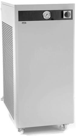
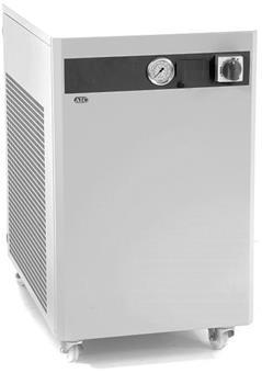
Mounting type Castors, 2 swivel, 2 braked Castors, 2 swivel, 2 braked
Acceptable environment Indoors or outdoors sheltered
Weight (kg) 100
Noise level (dB(A)@1m) ≤65 ≤65
Toolless access Top cover Top cover
Technology Air blast Air blast
Control method None, continuous fan None, continuous fan
Temperature stability Load & ambient dependent Load & ambient dependent
Cooling capacity with 'setpoint' 5°K above ambient 4kW 6kW
Cooling capacity with 'setpoint' 10°K above ambient 8kW 12kW
Cooling capacity with 'setpoint' 20°K above ambient 16kW 24kW
Maximum ambient +50°C +50°C
Design flowrate 12L/min 18L/min
Maximum THR (Total Heat Rejection) Applied load, plus power in Applied load, plus power in
Maximum permissible return line temperature +65°C +65°C
System volume 11L 11L
Pump options P10, P17 P17
Pressure relief Spring loaded PRV Spring loaded PRV
Standard fittings 1/2" BSPPF 1/2" BSPPF
Standard chemical compatibility Tap water, water-glycol mix
Tap water, water-glycol mix
1st party approvals CE, UKCA CE, UKCA 3rd party approvals UL-ready UL-ready
Empty fluid reservoir alarm Standard, process stop Standard, process stop
Low fluid flow alarm Optional Optional
Temperature display Optional Optional
Temperature out of range alarm Optional Optional
Motor thermal overload Standard Standard
Cooling system
Water system
Four 250mm axial fans, UL-approved, IP55.
Pair of PED-compliant coils.
Fluid level switch
Pump motor UL-approved
Pump motor thermal overload
Six 250mm axial fans, UL-approved, IP55.
Trio of PED-compliant coils.
Fluid level switch
Pump motor UL-approved
Pump motor thermal overload
Overcurrent protection Standard, via GV2 breaker Standard, via GV2 breaker
Overcurrent fault-cleared restart mode Manual restart
Interlock-restored restart mode
Manual by default.
Specify automatic with 'A' suffix on model number
Emergency off Not present
Warranty options 2-year parts, 1 year labour Enhanced warranty options
Manual restart
Manual by default.
Specify automatic with 'A' suffix on model number
Not present
2-year parts, 1 year labour Enhanced warranty options
+44(0) 1530839998
Service@thermalexchange.co.uk
Support@app-therm.com
Date 8/SEP/2022
For your safety, we draw your attention to the following warning and caution marks throughout the manual Warning symbols can be found on the unit. Ensure you have read through all warnings before starting the unit. The safe operation of ATC products always remains the responsibility of the operator. This equipment is intended to be used as a liquid temperature conditioning device – it requires no external pump, nor any further manipulation of temperature. If the equipment is used in a manner not specified by the manufacturer, the protection provided by the equipment may be impaired. Failure to comply with a ‘warning’ may result in personal injury or death. ATC does not accept any liability for injury caused through use of this equipment.


Caution; Failure to comply with a caution will invalidate product warranty and absolve ATC from any liability, howsoever caused, and could result in permanent damage to equipment.
Caution; Filling/topping up of the tank should only be undertaken with the unit switched off, to prevent back-filling of the fluid.
Caution; This product contains no user-serviceable parts. Repair and service requires specialized knowledge and tools to be provided by ATC or its local agent. Any unauthorized tampering with the heat exchanger system automatically invalidates warranty.
Warning; Hot and cold surfaces are present during operation. Take caution and care when touching pump during operation.
Warning; Water pressures of up to 10 bar during operation.
Warning; Water and electricity near one another. Always ensure the unit is isolated before service. The product is protected from overcurrent by GV2-type overload device. Never bypass this component.
During fault diagnostics and maintenance, it may be necessary to remove panels, which expose the operator to the dangers of pressurized systems, hot or cold pipes and electrical circuits. Only qualified personnel who are aware and equipped to deal with these systems should only carry out such work.
Any temporary electrical supply to the chiller should be correctly earthed and connected through an earth leakage trip.
In case of unexpected coolant leakage, safety glasses should always be worn when the chiller is operated with the covers removed.
Under no circumstances leave the cooler unattended with the side panels removed.
Never alter settings of pressure switches, overloads, circuit breakers or any safety device without first consulting Applied Thermal Control.
+44(0) 1530839998
Service@thermalexchange.co.uk
Support@app-therm.com
Date 8/SEP/2022 Author(s) MJH
Specific technical product information is provided in the following series of annexes.
Annex A-5 210226 Shipping & Unpacking - Weighing over 60kg, on castors
Annex B-2 211203 Site & Environmental Requirements for A01,03,08,12-Series
Annex C-6 210302 Installation - Generic air-cooled with 0.5inch fittings
Annex C-8 211203 Installation - Generic air-cooled with 1.0inch fittings
Annex D-3 201007 Fluid Handling & Startup Procedures - Generic
Annex E-0 211203 No controller
Annex E-5 210301 KR3 - how to use (for coolers with setpoint control)
Annex E-5M 220309 KR3 Program A08 A12 variable speed fan
Annex F-3 201007 PD pump using discrete PRV
Annex F-5 220309 Centrif or turbine pump without relief
Annex G-10 220309 Troubleshooting - Initial help for A-Series
Annex H-1 191121 End-user maintenance - air-cooled units with water as fluid
Annex I-7 220310 Maintenance for technicians - Generic airblast
Annex J-5 200706 EU Compliance Statement - Conflict Minerals
Annex J-6 210212 EU DoC A-series
Annex J-7 200715 EU Compliance Statement - REACH
Annex J-8 200827 EU Compliance Statement - POPs
Annex J-10 201111 EU Compliance Statement - RoHS
Annex J-17 220310 UKCA DoC - A-Series
Annex K-1 200623 Standard warranty terms of ATC
Annex M-7 220310 Recommended spares, A Series
Annex R-3 200203 SDS Hexid A4 v6.4


+44 (0) 1530 839 998
Service@thermalexchange.co.uk
Support@app-therm.com
Please check that both the packaging and the unit are undamaged. If there is any doubt, it is vital that you inform both ATC and the carrier. There are no hidden shipping bolts or other fixings. You should inspect the packaging for signs of transit damage before signing for the unit, and if possible, unpack the unit before signing. Once you have signed for the goods, ATC cannot be held responsible for any transit damage subsequently found.
As the unit weighs >60kg, ATC recommends it should be lifted with slings through the underside, using a forklift or overhead crane ATC highly recommends that it is not manually lifted, and that safe slinging and lifting practices are adhered to.
Remove the unit from its original packaging and ensure that there is no packaging left around the cooling ducts. There is no internal product packaging that requires the chiller to be opened.
Please retain all packaging in the unlikely event that the chiller needs to be returned to our local representatives.
39 Hayhill Industrial Estate
Barrow-upon-Soar, Loughborough
LE12 8LD, United Kingdom
+44 (0) 1530 839 998
Service@thermalexchange.co.uk
Support@app-therm.com
This guide applies to certain A-Series products only. Please find below the requirements for all services and conditions necessary for years of trouble-free running. If you require more detail, please contact ATC for support on sales@app-therm.com or using the contact information at the top of this page.
Storage temperature range. Without process fluids, -20°C to +70°C.
Storage humidity range. Non-condensing, relative humidity 5% to 95%. Before starting product, allow product to acclimate for 24h in location of use when storing outside operating humidity range.
Operating temperature range. With appropriate process fluids, -20°C to +65°C. 4
Operating humidity range. 80% for ambient temperatures up to +31°C (+88°F), decreasing linearly to 50% relative humidity at +40°C (+104°F) ambient temperature.
5 Hard, level surface. A level surface is important for ensuring proper filling and allowing air to escape.
L1/L2/E
Clearance. Clearance is required to;
a) Ensure the on/off switch on the front face is unobstructed to allow access in case of emergency.
b) Fit hoses and electrical supply to the rear of the unit allowing recommended bending radii.
c) Allow maintenance access points on top and side panels to be removed
d) Allow process to take place – A01/A03 air-on face is the front of unit – 0.5m is recommended – the coolest, cleanest air that can be provided will improve performance. A08/A12 air-on face is the righthand side. Air-off faces are every other vented face – 0.5m clearance is recommended on at least 1, preferably 2 of the rear, left and right sides. 8 Plumbing. Tubing, piping or hose must be clean and compatible with the fluid to be used. The product is compatible with deionized water, tap water and water-glycol mixtures such as Hexid A4 and A6. Ensure the connected pipework is suitable for handling up to 20L/min at system pressure ≥6bar.
9 Indoor use only. Altitude up to 2000m above sea level. Ensure the unit has adequate ventilation.
10 Installation category. Transient overvoltage category II; Pollution degree 2. Temporary overvoltages occurring on mains supply are acceptable within limits defined in the categories.
Caution; Always use ATC recommended fluids in our products – many sealing compounds and materials are present and unapproved fluids have the potential to corrode your application and damage seals.
Caution; Do not use inadequately rated wiring. Consult an electrician if you are unsure.
Caution; The safety of any system incorporating the equipment is the responsibility of the assembler of the system.
Caution; Do not replace detachable mains cords with inadequately rated cords. Contact ATC for appropriately rated products.
39 Hayhill Industrial Estate
Barrow-upon-Soar, Loughborough
LE12 8LD, United Kingdom
+44 (0) 1530 839 998
Service@thermalexchange.co.uk
Support@app-therm.com
Date 9/MAR/2022
This guide applies to the following product groups;
- K-Series, R-Series and G-Series refrigerated units, where heatload is rejected to air - A-Series airblast units, where heatload is rejected to air
Having ensured that your installation meets all site requirements, it is best practice that the fluid lines between your application and the chiller have the following characteristics.
1 Short in length – this reduces friction-based pressure drop and addition ambient heat load.
2 Large diameter bore – at least 12mm (1/2”)
3
Free from 90° bends – to limit the effects of water hammer. If this cannot be avoided, sharp changes of direction should be minimized so far as possible. Doing this correctly can yield higher pump performance and extend time between maintenance intervals. It will also reduce electrical energy consumption.
4 Clean – If your installation is to existing pipe work, it is good practice to flush the system with either a commercially available central heating cleaner or 5% acetic acid solution. The system should be flushed clean with tap water to remove all traces of cleaner prior to filling the system. Failing this, it is recommended to use a domestic bleach in solution with tap water, diluted to the point where the bleach can longer be smelled by human nose.
5 Opaque, ideally black – to inhibit light passing through the tube and algae building up. Alternatively, solid ABS or copper pipe can be used where application chemistry allows.
6
Insulation, where low temperature process is planned – the process line from chiller to application contains the feed of low temperature fluid. Insulation prevents heat from entering this line and can promote better stability. Uninsulated return lines are helpful where free cooling can be obtained by allowing heat to transfer to air – likewise, insulating the return line is helpful if the fluid temperature is below ambient.
Caution; Never use transparent tubing. UV light will pass through, prompting growth of organic contamination.
1
Standard units are supplied with 1/2” British Standard Pipe Parallel Female (BSPPF) threads (also known as G threads (ISO228)) by default. These fittings are not valved and will ‘drop’ the volume of the system if left open to atmosphere.
2 Ensure the appropriate thread sealants are used in the fitting of adapters to hose. For metallic mating parts, we recommend Loctite 577. For plastic adaptors such as those supplied with the product, we recommend using ~8-12mm wide PTFE tape, wrapped around the male thread before tightening.
3 Ensure that the system is correctly connected. The ‘donut’ labels around the ports are clearly marked with inlet and outlet symbols and function in both English and French language. Ports marked as outlet means fluid leaves the product and must be connected to the process inlet
4 Check all joints are tight and leak free.
5 Where this product is incorporated into other equipment, it is the responsibility of the assembler to ensure safety.
1 In situations where the chiller is situated physically lower than the application being cooled, fluid will apply pressure to the water circuit of the product.
The weakest seal is normally the tank lid, and this is typically where fluid will escape the unit.
Ideally, the product will be located higher or level with the product water-line. If this is not possible, a nonreturn solenoid valve kit can be installed as an optional standard assembly.
4 Please raise any questions with the sales team on sales@app-therm.com
39
LE12 8LD, United Kingdom
+44 (0) 1530 839 998
Service@thermalexchange.co.uk
Support@app-therm.com
Date 9/MAR/2022
This guide applies to the following product groups; - K-, G-, W-Series refrigerated units, where heatload is rejected to air. - A-Series airblast units, where heatload is rejected to air.
Having ensured that your installation meets all site requirements, it is best practice that the fluid lines between your application and the chiller have the following characteristics.
1 Short in length – this reduces friction-based pressure drop and minimizes exposure to ambient heat load.
2 Large diameter bore – we recommend hose internal diameter (ID) on 1” BSPPF fittings is no smaller than 3/4” (19mm), and preferably larger than 1” (25.4mm).
3 Free from 90° bends – to limit the effects of water hammer. If this cannot be avoided, sharp changes of direction should be minimized so far as possible. Doing this correctly can yield higher pump performance and extend time between maintenance intervals. It will also reduce electrical energy consumption.
4
5
6
Clean – If your installation is to existing pipe work, it is good practice to flush the system with either a commercially available central heating cleaner or 5% acetic acid solution. The system should be flushed clean with tap water to remove all traces of cleaner prior to filling the system. Failing this, it is recommended to use a domestic bleach in solution with tap water, diluted to the point where the bleach can longer be smelled by human nose. ATC can offer commercial-grade cleaning solutions – contact us for information.
Opaque, ideally black – to inhibit light passing through the tube and algae building up. Alternatively, solid ABS or copper pipe can be used where application chemistry allows.
Insulation, where low temperature process is planned – the process line from chiller to application contains the feed of low temperature fluid. Insulation prevents heat from entering this line and can promote better stability. Uninsulated return lines are helpful where free cooling can be obtained by allowing heat to transfer to air – likewise, insulating the return line is helpful if the fluid temperature is below ambient.
Caution; Never use transparent tubing. UV light will pass through, prompting growth of organic contamination.
This document described the use of 1” British Standard Pipe Parallel Female (BSPPF) threads (also known as G threads (ISO228)) by default. These fittings are not valved and will ‘drop’ the volume of the system if left open to atmosphere. 2
Ensure the appropriate thread sealants are used in the fitting of adapters to hose. For metallic mating parts, we recommend Loctite 577. For plastic adaptors such as those supplied with standard products, we recommend using ~8-12mm wide PTFE tape, wrapped around the male thread before tightening.
3
Ensure that the system is correctly connected. The ‘donut’ labels around the ports are clearly marked with inlet and outlet symbols and function in both English and French language. Ports marked as outlets mean fluid leaves the product and must be connected to the process inlet or house water return line.
4 Check all joints are tight and leak free.
5 Where this product is incorporated into other equipment, it is the responsibility of the assembler to ensure safety.
1 In situations where the chiller is situated physically lower than the application being cooled, fluid will apply pressure to the water circuit of the product.
The weakest seal is normally the tank lid, and this is typically where fluid will escape the unit.
Ideally, the product will be located higher or level with the product water-line. If this is not possible, a nonreturn solenoid valve kit can be installed as an optional standard assembly.
4 Please raise any questions with the sales team on sales@app-therm.com
a) Check all application valves are open, including solenoid valves and variable position valves.
i) The product will require an open water circuit to pump into
ii) Any obstructions can increase the time, or entirely prevent the bleeding of air from the system.
b) Remove the cap from the tank lid on the top of the product.
i) Fill the tank to just underneath the bottom of the filling port.
c) Turn your attention to the main power switch.
i) Immediately after toggling this switch assuming that the power cord is connected and turned on at the wall the product will begin to pump water
ii) Leave the product to run until it cuts out on the level switch interlock.
iii) Turn the unit off at the mains switch
iv) Fill the tank again to lift the level switches.
v) Start the product again until the unit cuts out again.
Caution; Do not run the pump dry. Do not deadhead the pump.
d) Repeat steps at c) until the chiller tank water level (if visible) doesn’t drop, and the chiller doesn’t cutout on its level switches.
e) With the unit now running;
i) Leave the cap off the tank for >30mins to allow air to escape, or very loosely screwed on to prevent water splashing out of the tank if the unit has a ‘flow through’ design.
f) Check the application and tubing for signs of leaks whilst the chiller is running.
i) Replace the tank lid fully when satisfied the system is full and bled of air.
a) Isolate the unit. Have a suitable bucket or drain on-hand.
i) Remove the tank lid to allow air into the system.
ii) Disconnect hoses individually. Be aware hoses as well as the unit are filled with fluid.
iii) Consider using the red transport plugs to block product ports to give yourself time to empty hoses before continuing to empty the product.
b) Local rules affect where fluid can be disposed of.
i) Ensure hazardous products do not enter the water course and are reclaimed from the unit for professional disposal.
+44 (0) 1530 839 998
Service@thermalexchange.co.uk
Support@app-therm.com
This guide may apply to your product if it is designed for continuous cooling or heating without any form of regulation, i.e., basic airblast products and KTR.
1
2
Some cooling technologies, such as airblast, are inherently safe when left to run without regulation. The worst an airblast can do to a process fluid is bring it down to ambient temperature. Naturally, a lot depends on where the airblast cooler is placed The same is feasible with an unregulated water-to-water product, although at time of writing, ATC do not make unregulated water-to-water heat exchangers.
In a refrigerated system, such at ATC’s KTR family, there is a valve that limits the lowest temperature the chiller can reach. These valves are robust and maintain their regulating ability over the lifetime of the product. They can be adjusted to allow sub zero operation; the operator must ensure appropriate process fluids are used to avoid freezing.
This guide may apply to your product if you require general navigation advice and help accessing settings. If you are planning to change the settings in any way, you may need a copy of the existing settings which are model dependent, signified by a letter on the end of Annex E-5, i.e. Annex E-5A.
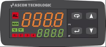
Physical navigation buttons, up, down, return and enter.
8888.8 is the actual read value on input sensor.
888.8 is the setpoint value.
4 Rectangles bottom left 1-4 display when output is active.
5 MAN LED shows in manual mode (fixed output value). 6 °C or °F shows units as settable in the ‘inP’ group 7 AL LED appears when output is beyond a set alarm point.
Using up and down buttons set the programmed password – full access is granted by entering ‘40’. ATC are not responsible for damage either to the chiller or the connected equipment as a result of changing parameters without ATC’s oversight.
During parameter modification the instrument continues to perform process control. In certain conditions, when a configuration change can produce a significant change to the process, it is advisable to temporarily stop the controller from controlling during the programming procedure (control outputs will be OFF). A password equal to 2000 + the programmed value (i.e. 2000 + 40 = 2040). The control will restart automatically when the configuration procedure will be manually closed.
Push the return button. If the password is correct the display will show the acronym of the first parameter group ‘inP’. Push button for more than 5 seconds, the instrument will come back to the “standard display”.
The configuration parameters are collected in various groups. Every group defines all parameters related with a specific function (control, alarms, output functions).
Push return button for more than 5 seconds, the instrument will come back to the “standard display”. For specific settings and guidance, review the controller datasheets provided by ATC. If you are not in receipt of these, please contact ATC using the information in the header of this document.
Return button; A short press allows to exit from the current parameter group and select a new parameter group. A long press allows you to close the configuration parameter procedure (the instrument will come back to the “standard display”).
Enter button; When the upper display is showing a group and the lower display is blank, this key allows to enter in the selected group. When the upper display is showing a parameter and the lower display is showing its value, this key allows to store the selected value for the current parameter and access the next parameter within the same group.
16 Up button; Allows to increase the value of the selected parameter.
17 Down button; Allows to decrease the value of the selected parameter.
18
Pushing both Return and Enter buttons moves back to the previous group. Press return first to start. The selection of the group is cyclic (on a carousel), so it is possible to move back around to the group you require.
39 Hayhill Industrial Estate
Barrow-upon-Soar, Loughborough
LE12 8LD, United Kingdom
+44 (0) 1530 839 998
Service@thermalexchange.co.uk
Support@app-therm.com
Date 9/MAR/2022 Author(s) MJH
Internal part number EA798 / 61-591
Manufacturer part number KR3
Program purpose
1) To maintain a fluid temperature within tolerance around set point.
2) To modulate a 0-10Vdc signal to control internal fans on an internal coil.
3) To set the parameters of the controller to within safe working limits.
diF2 n/a o3.AL n/a
di.A 0 o3Ac n/a
Applied Thermal Control Ltd
39 Hayhill Industrial Estate
Barrow-upon-Soar, Loughborough
LE12 8LD, United Kingdom
+44 (0) 1530 839 998
Service@thermalexchange.co.uk
Support@app-therm.com
Date 9/MAR/2022
Author(s) MJH
t.Job 0
Pr.G1 n/a
n/a
n/a
n/a
n/a
Pr.t2 n/a oPEr Auto
Pr.b2 n/a
Pr.E2 n/a
Pr.S3 n/a
Pr.G3 n/a
Pr.t3 n/a
Pr.b3 n/a
Pr.E3 n/a
Pr.S4 n/a
Pr.G4 n/a
Pr.t4 n/a
Pr.b4 n/a
Pr.E4 n/a
Pr.St n/a
8LD, United Kingdom
+44 (0) 1530 839 998
Service@thermalexchange.co.uk
Support@app-therm.com
Date 7/OCT/2020 Author(s) MJH
This arrangement comprises a positive displacement pump (most commonly a rotary vane type) with a springloaded pressure relief valve to provide better overpressure setting control with minimal flow losses compared to fixed orifice bypasses/reliefs This annex describes ATC’s default settings and how to adjust the system
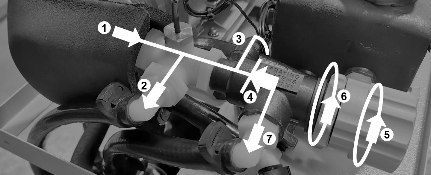
It is important to understand the basic principle that all else being equal, higher flow results in a higher demand for pressure. The motor generates the power required to turn the pump head and create that pressure. The more restrictive a water circuit is, the higher the pressure required to maintain flowrate. Positive displacement pumps are designed to generate high pressure and are mechanically tight - their RPM dictates flowrate See image;
1) Pump discharge – fluid leaves the pump head and enters the gauge-tee assembly. It passes the temperature sensor at the tee, and when the pressure relief is inactive, fluid heads towards no. 2.
2) Outlet to process – fluid heads out of the product to the application. Whatever restrictions lie downstream, fluid leaving this point has not passed through the pressure relief valve.
3) Pressure gauge connection – connection to a pressure gauge on the front panel of the product. This displays the pressure in the water circuit, at the pump outlet, not the application which will be lower.
4) Pressure Relief Valve (PRV) – spring tension in the body of the PRV determines whether fluid travels through point 2 or passes through to point 7.
5) PRV adjustment knob – rotate clockwise to increase maximum delivery pressure. Rotate anti-clockwise to limit maximum delivery pressure.
6) PRV adjustment locknut – release this locknut to adjust no.5 Ensure it is tightened once adjustments are made. If it is not, vibration may cause the adjustment knob to move on itself.
7) Bypass flow outlet – where the pressure requirement to overcome restrictions downstream of no.2 rises to be higher than the setting at no.5, the spring inside no.4 will compress and allow liquid to start bleeding through to no.7. It is important to understand that the nature of the spring means there can be no black and white point for pressure relief setting – the spring will slowly compress and bleed flow until all flow passes through no.7. When fully bypassing, all flow stays inside the chiller to protect the application.
+44 (0) 1530 839 998
Service@thermalexchange.co.uk
Unless otherwise agreed at point of sale, the default setting for this type of pump and PRV arrangement is 3.33bar (50psi) In the absence of external calibrated pressure gauges, it’s possible to use the chiller itself to set this value;
8) Isolate the chiller – always isolate before performing work.
9) Disconnect from the application if already connected – review the draining procedure in Annex D.
10)Connect the chiller’s process inlet to process outlet – a short run of hose around 1-2m (3-6ft) will be adequate
11)Start the chiller and follow the fill process from Annex D – fluid will now be running through a short loop with very low pressure required to overcome the restriction.
12)With the chiller running, very slowly kink the short run of hose fitted above – this simulates a blocked application – this is known as ‘deadheading’ the pump. Without PRV, the pump motor would stall or hoses might blow off Watch the pressure gauge climb as you apply the kink.
13)The pressure gauge will eventually stop climbing with the hose fully kinked – note the value; this is the setting of the PRV where all flow is bypassed.
14)Refer to points 5) and 6) above to adjust if required – contact ATC if you’re unsure over whether your desired setting is reasonable for the product you have.
Date 9/MAR/2022 Author(s) MJH
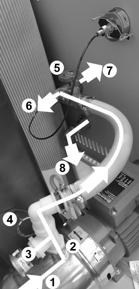
This arrangement comprises a centrifugal or turbine type pump with typically a gate, needle or ball valve downstream of the pump discharge to throttle the pump flowrate. Without any relief, it is critical to ensure the pump is not deadheaded (no flow, and no relief) From many years of experience, ATC have found this method of maintaining a high head pressure on the pump to extend the service life and all but eliminate pump leaks. The valve is closed slowly until the desired flowrate or maximum pressure is met for the application, read from the panelmounted pressure gauge This annex describes ATC’s default settings and how to adjust the system
It is important to understand the basic principle that all else being equal, higher flow results in a higher demand for pressure to overcome forces of friction and viscosity. The pump motor generates the motive force required to turn the pump head and create that pressure.
B
1
The more restrictive a water circuit is, the higher the pressure required to maintain flowrate. Centrifugal and turbine-type pumps are designed to generate lower pressure and higher flowrates. They are mechanically loose which usually leads to a longer lifetime in service.
Pump suction – centrifugal and turbine pumps are not self-priming. The suction port/inlet must be flooded by a source of liquid. This is usually the tank with water line higher than pump suction.
2 Pump discharge – connection to the application –more restrictions downstream reduce flowrate.
3
4
5
Service pressure gauge – this displays the pressure between pump discharge and throttling valve. This is normally higher than the process pressure gauge. It should never be lower than 2bar.
Temperature sensor – on systems where temperature control hardware is fitted, the sensor is typically in the discharge line.
Fixed orifice throttling valve – if fully closed (fully CW) the pump is ‘deadheaded’ and will lead to damage in the short-term. If fully open (fully CCW), the pump is not restricted in any way – dependent on process pressure and flow requirements, the valve can be closed slowly until the desired conditions are reached.
6
Process pressure gauge – reads the pressure in the line that is created when the customer’s application is connected.
7 Discharge to process – cooled/chilled water connection to the application
8
Return from process – typically sent to either tank, airblast radiator or refrigeration heat exchanger.
Service@thermalexchange.co.uk
2
3
4
Units with this type of pressure and flow control are typically shipped fully open to prevent deadheading. When the end user or commissioning engineer first runs the unit, the full force of the pump will be available without relief – if this is likely to cause damage, the valve can be closed partially, and the service pressure gauge monitored.
Set the chiller/cooler running whilst connected to the application – bleed air from the system as per instruction in Annex D.
Using the service mounted process gauge, use pressure to determine flowrate – centrifugal and turbine pump flowrates can be determined by reading the pump curve.
Where pressure or flow is too high, the throttling valve can be closed down – where pressure or flow is too low, it can be opened. Typically ATC size pumps to provide some excess pressure availability
5 Ensure the service pressure gauge is always at a minimum of 2bar.
39
+44 (0) 1530 839 998
Service@thermalexchange.co.uk
Support@app-therm.com
Date 9/MAR/2022 Author(s) MJH
Check the tank is filled past the level switch to ensure it can run.
Check temperature of fluid and pump motor. In the case of these reaching temperatures that could cause damage, the unit will switch off.
Unit not running
Noisy operation
Fluid lines becoming fouled / containing biological matter
Check overload state and ensure internal fuses have continuity.
Check pump motor interlock chain
Check supply is at correct voltage.
Air in the system the has not purged causing pump vanes to rattle (where fitted).
Bearing failure in fan or pump motor causes grinding / intermittent knocking noise.
Fan blade is running off center and grinding against coil housing.
Not using opaque tubing can lead to UV light passing through the tubing, prompting growth of organisms.
Not following maintenance schedule for cleaning/flushing.
Fluid may be incompatible with the materials used in chiller construction. Contact ATC to ensure the fluid is compatible.
Fluid seen leaking from system
Rapid changes in system temperature can cause some materials to change shape at a faster rate than others and open leak paths. Contact ATC to discuss alternative materials and parts in water circuit construction if your temperature range goes beyond the standard for this product range.
In case of centrifugal pump being fitted, minimum head of 2bar has not been observed.
Excess application thermal heat load.
See Annex G-2 for a description on how to calculate this.
Poor cooling capacity (undercooling)
Excess cooling capacity (overcooling)
Ambient air temperature has increased from nominal requirement, or flow has reduced from cooling fan.
Process fluid pump high flowrate can yield a low delta T, i.e. outlet temperature to application will be higher than desired and return temperature will be lower than nominal. Cooling capacity will be the same.
Reduction in flowrate in an airblast system without process temperature control can yield outlet temperature much closer to ambient (lower) than system design nominals. For nominals, please contact sales@app-therm.com.
One or more component in failure mode generating heat beyond that which the cooler can reject.
Cooler oversized at point of design or thermal load overestimated – this can be remedied by blocking part of the cooling coil.


Applied Thermal Control Ltd
39 Hayhill Industrial Estate
Barrow-upon-Soar, Loughborough
LE12 8LD, United Kingdom
+44 (0) 1530 839 998
Service@thermalexchange.co.uk
Support@app-therm.com
Date November 2019 Compiled by MJH
Caution; Failure to carry out service at the specified intervals may permanently damage your equipment.
Print this sheet out and display close to the chiller to maximize the visibility of maintenance requirements.
Check fluid level – top up as required.
Check the condenser is free from dust or accumulation of debris.
Drain process fluid and replace with fresh fluid.
Check for fluid leaks throughout chiller and application.
Clear any debris from inside the chiller
A vacuum cleaner is recommended for cleaning out the condenser, while soft cloths and IPA are recommended for cleaning metallic surfaces. If any spillages have occurred, best practice is to allow the water to evaporate off and wipe up remaining glycol residue with a cloth. Always clean with power supply isolated.
Caution; Never blow out the condenser with compressed air.
Caution; If the mains lead is lost or damaged, contact ATC who will be able to supply a replacement of the correct specification.
+44 (0) 1530 839 998
Service@thermalexchange.co.uk
Support@app-therm.com
Date 10/MAR/2022
Warning; Water pressures of up to 10 bar during operation.
Warning; After switching off, the condenser cooling fan blades continue to rotate. Do not attempt servicing whilst the blades are rotating.
Warning; All chillers contain water and electricity in close proximity. Ensure the unit is isolated before service. This product is protected from overcurrent by fuses (or MCB) on the mains inlet. Never bypass the overcurrent protection
Following service or repair by a trained technician;
a) Ensure any electrical connections that may have been disturbed are given the ‘tug-test’
b) Ensure earth bonding conductors are re-attached.
c) Ensure the correct fuses are in place.
d) Ensure the mains cord being used is to specification, and is free from damage
e) Subject the unit to a PAT test to ensure the unit is safe before running.
f) Ensure there are no leaks inside or outside the unit.
g) Using the wiring schematic for guidance, simulate faults to check each interlock’s function.
+44 (0) 1530 839 998
Service@thermalexchange.co.uk
Support@app-therm.com
Date 03/FEB/2021 Author(s) MJH
Applied Thermal Control (ATC) adheres to and embraces the ethical values that support our everyday activities. As an expression of these principles and ethical values, ATC adheres to the principle of responsible sourcing of components containing precious and non-precious metals and metal salts in compliance with applicable laws and regulations.
The metals considered are Tantalum (Ta), Tungsten (W), Tin (Sn) and Gold (Au). ATC actively sources components from suppliers known to be reputable and could demonstrate compliance upon request with the Conflict Minerals acts and guidelines.
ATC uses Gold and Tin in electrical components, on PCBs and in rotating machinery, as governed by technical requirements of products. These metals could potentially originate from conflict mineral sites. As many of our suppliers do not purchase these metals direct from smelters, both they and ATC must rely heavily on information that will be provided by their suppliers to determine the source and chain of the metals in those products.
ATC is committed to working with its customers and supply chain to meet the customer’s specification and requirements with regards to traceability, sourcing requirements and restrictions. ATC commits that, to the best of our knowledge, our suppliers are complying with the conflict minerals act as stated in their documentation. These statements are reviewed, and updates obtained as required.
Mitchell Howard, Technical Manager Signed in Coalville, UK, date 6/JUL/2020
Applied Thermal Control Ltd
39 Hayhill Industrial Estate
Barrow-upon-Soar, Loughborough
LE12 8LD, United Kingdom
+44 (0) 1530 839 998
Service@thermalexchange.co.uk
Support@app-therm.com
Date 12/FEB/2021 Author(s) MJH
Document layout; Governed by Machinery Directive 2006/42/EC, Annex II.
Applied Thermal Control Ltd, 39 Hayhill Industrial Estate, Barrow-upon-Soar, Loughborough, LE12 8LD, UK.
AUTHORISATION TO COMPILE THE TECHNICAL
Mitchell Howard, Applied Thermal Control Ltd, 39 Hayhill Industrial Estate, Barrow-upon-Soar, Loughborough, LE12 8LD, UK.
Generic denomination; A-Series
Function; Recirculating Cooler
Model; All with ‘A’ prefix.
Type; Air-cooled heat exchanger
Serial number;
Commercial name; As above.
Not applicable
QMS International Ltd, Muspole Court, Muspole Street, Norwich, NR3 1DJ, United Kingdom. ASCB Registered; 201409-2
The manufacturer declares that the machinery described above fulfils all the relevant provisions of the;
• Machinery Directive 2006/42/EC.
• EMC Directive 2014/30/EU, via harmonised standards;
o IEC 61000-6-2:2005 (Immunity for industrial environments).
o IEC 61000-6-4:2006 +A1:2011 (Emission for industrial environments).
• Low Voltage Directive 2014/35/EU.
• RoHS Directive 2011/65/EU (RoHS 2);
o The machinery above contains no Lead (Pb), Mercury (Hg), Cadmium (Cd), Hexavalent Chromium (Cr6+), Polybrominated Biphenyls (PBB) or Polybrominated Diphenyl Ether (PBDE).
• RoHS Directive (EU) 2015/863 (RoHS 3);
o Bis(2-Ethylhexyl) phthalate (DEHP): < 1000 ppm
o Benzyl butyl phthalate (BBP): < 1000 ppm
o Dibutyl phthalate (DBP): < 1000 ppm
o Diisobutyl phthalate (DIBP): < 1000 ppm
39 Hayhill Industrial Estate
Barrow-upon-Soar, Loughborough
LE12 8LD, United Kingdom
+44 (0) 1530 839 998
Service@thermalexchange.co.uk
Support@app-therm.com
Date 03/FEB/2021 Author(s) MJH
REACH is a regulation of the European Union, adopted to improve the protection of human health and the environment from the risks that can be posed by chemicals, while enhancing the competitiveness of the EU chemicals industry. REACH places the burden of proof on companies. To comply with the regulation, companies must identify and manage the risks linked to the substances they manufacture and market in the EU. They have to demonstrate to ECHA how the substance can be safely used, and they must communicate the risk management measures to the users. If the risks cannot be managed, authorities can restrict the use of substances in different ways. In the long run, the most hazardous substances should be substituted with less dangerous ones. REACH stands for Registration, Evaluation, Authorization and Restriction of Chemicals. It entered into force on 1/JUN/2007.
Substances under Annex XVII are restricted either in full (not to be used at all) or for specific uses (can be used in some uses but cannot be used in identified uses).
Applied Thermal Control has contacted all our suppliers and to the best of our knowledge, none of the articles that we sell intentionally contain any of the Annex XVII substances currently on the candidate list in concentrations of >0.1% by weight.
Substances under Annex XIV require authorization to use in the EU after sunset date, require communication to downstream recipients when over threshold (0.1% w/w at article level) and require notification to ECHA when SVHC over threshold and imported over 1000kg annually and use not already registered.
Applied Thermal Control has contacted all our suppliers and to the best of our knowledge, none of the articles that we sell intentionally contain any of the Annex XVII substances currently on the candidate list in concentrations of >0.1% by weight. SVHC LIST COMPLIANCE
Substances of Very High Concern (SVHC) require communication to downstream recipients when over threshold (0.1% w/w at the article level), notification to the European Chemicals Agency (ECHA) when SVHC over threshold and when imported over 1000kg annually and use not already registered.
Applied Thermal Control has contacted all our suppliers and to the best of our knowledge, none of the articles that we sell intentionally contain any of the Annex XVII substances currently on the candidate list in concentrations of >0.1% by weight.
Applied Thermal Control
39 Hayhill Industrial Estate
Barrow-upon-Soar, Loughborough
LE12 8LD, United Kingdom
+44 (0) 1530 839 998
Service@thermalexchange.co.uk
Support@app-therm.com
Date 03/FEB/2021 Author(s) MJH
POPs stands for persistent organic pollutants. In Europe, the global Stockholm Convention is implemented through POPs legislation. POPs are organic substances that persist in the environment, accumulate in living organisms and pose a risk to our health and the environment. They can be transported by air, water or migratory species across international borders, reaching regions where they have never been produced or used. International risk management is necessary as no region can manage the risks posed by these substances alone.
The European Parliament (and Council) issued regulation 2019/1021 on 20/JUN/2019, and further amended (regulation 2020/784) on 8/APR/2020
Pesticides;
Aldrin, Chlordane, DDT, Dieldrin, Endrin, Heptachlor, Hexachlorobenzene, Mirex, Toxaphene
Industrial Chemicals; Hexachlorobenzene, Polychlorinated Biphenyls (PCBs)
Industrial Chemical Byproducts; Hexachlorobenzene byproducts; Polychlorinated dibenzo-p-dioxins and polychlorinated dibenzofurans (PCDD/PCDF), and PCBs.
Perfluorooctanoic acid (PFOA), its salts and PFOA-related compounds.
We certify that to the best of our knowledge, based upon up-to-date information from our suppliers, all products supplied by Applied Thermal Control are fully POPs compliant in accordance with regulations and amendments above mentioned. DECLARATION
Mitchell Howard, Technical Manager Signed in Barrow-upon-Soar, UK, date 27/AUG/2020
Date 03/FEB/2021 Author(s) MJH
The RoHS Directive places restrictions on the use of certain hazardous substances in electrical and electronic equipment (EEE). RoHS compliance has been required for many years, however in 2014 it became a mandatory requirement under CE Marking. ATC products do not clearly fall within any of the existing categories of equipment, but as of 23/JUL/2019, all EEE not covered falls within scope of the directive. In contrast to RoHS 1, RoHS 2 is a CE marking Directive, and requires, for finished EEE, the use of the CE mark on the product to show compliance. The responsibility for affixing the CE mark resides with the manufacturer.
Adopted in February 2003 by the EU and taking effect on 1/JUL/2006, RoHS 1 restricted the use of 6 hazardous materials;
1) Lead (Pb)
2) Mercury (Hg)
3) Cadmium (Cd)
4) Hexavalent Chromium (Cr6+)
5) Polybrominated Biphenyls (PBB)
6) Polybrominated Diphenyl Ether (PBDE)
We certify that to the best of our knowledge, based upon up-to-date information from our suppliers, all products supplied by Applied Thermal Control are fully RoHS 1 compliant.
Adopted in July 2011 by the EU and taking effect on 2/JAN/2013, RoHS 2 expands the scope of RoHS 1 by adding new categories. RoHS 2 compliance is required to CE mark the product. Compliance with RoHS 2 is mandatory from 22/JUL/2019.
We certify that to the best of our knowledge, based upon up-to-date information from our suppliers, all products supplied by Applied Thermal Control are fully RoHS 2 compliant.
3
Adopted in 2015 by the EU and taking effect from 22/JUL/2019, RoHS 3 adds four additional substances to RoHS 1’s list.
1) Bis(2-Ethylhexyl) phthalate (DEHP): < 1000 ppm
2) Benzyl butyl phthalate (BBP): < 1000 ppm
3) Dibutyl phthalate (DBP): < 1000 ppm
4) Di-isobutyl phthalate (DIBP): < 1000 ppm
We certify that to the best of our knowledge, based upon up-to-date information from our suppliers, all products supplied by Applied Thermal Control are fully RoHS 3 compliant.
Applied Thermal Control Ltd
39 Hayhill Industrial Estate
Barrow-upon-Soar, Loughborough
LE12 8LD, United Kingdom
+44 (0) 1530 839 998
Service@thermalexchange.co.uk
Support@app-therm.com
Date 10/MAR/2022
Author(s) MJH Page 1 / 1
UKCA DECLARATION OF CONFORMITY (DoC)

Demand created by;
The Product Safety and Metrology etc. (Amendment etc.) (EU Exit) Regulations 2019
Applied Thermal Control Ltd, 39 Hayhill Industrial Estate, Barrow-upon-Soar, Loughborough, LE12 8LD, UK.
AUTHORISATION TO COMPILE THE TECHNICAL FILE
Mitchell Howard, Applied Thermal Control Ltd, 39 Hayhill Industrial Estate, Barrow-upon-Soar, Loughborough, LE12 8LD, UK.
DESCRIPTION & IDENTIFICATION OF MACHINERY
Generic denomination; A-Series
Function; Water cooler
Model; All with ‘A’ prefix.
Type; Airblast
Serial number;
Commercial name; As above.
Not applicable
QMS International Ltd, Muspole Court, Muspole Street, Norwich, NR3 1DJ, United Kingdom. ASCB Registered; 201409-2
The manufacturer declares that the machinery described above is in conformity with the relevant statutory requirements applicable to the specific product. The manufacturer takes full responsibility for the product’s compliance.
• Supply of Machinery (Safety) Regulations 2008
• Electromagnetic Compatibility Regulations 2016
• Electrical Equipment (Safety) Regulations 2016
• The Restriction of the Use of Certain Hazardous Substances in Electrical and Electronic Equipment Regulations 2012
Robert Poniatowski, CEO
Signed in Barrow-upon-Soar, UK, date 10/MAR/2022
a) For how long is my ATC product warrantied?
ATC provides a comprehensive return to base 2-year parts, 1-year labor warranty from delivery as standard on all new equipment, provided it has been installed and operated in accordance with the manual.
b) Where will ATC fulfill the product warranty?
ATC’s standard warranty terms are Return to Base (RTB) – issues with chillers are often easily solvable over the phone or email, or by reviewing ATC’s technical guidance on the web and in the product manual. On occasion, at the discretion of ATC, goods may be serviced on site FOC or a service loan unit may be supplied. Warranty cover excludes the cost of travel by engineers and loan unit rental charges. Obtaining onsite service for a product, even in full warranty, is a chargeable service.
c) Who is liable for shipping charges in the event of warranty failure?
During the first year of the warranty period, freight costs for shipping to ATC are for the customer’s account. Freight costs for shipping from ATC are for ATC’s account. During the second year of the warranty, freight costs to and from ATC are for the customer’s account
d) I’m experiencing problems with my chiller. It’s within warranty – what do I do next?
Contact ATC to discuss the issue you are having. The contact details in the header of this document are an ideal place to start. Be sure to have your model number and serial number on-hand to aid those attempting to solve remotely.
e) Telephone support couldn’t fix my chiller – what do I do next?
An RMA form must be completed. This allows both the end-user and ATC to clarify your details, to set the party responsible for shipping costs, and to set a different return address if desired. Shipping advice is provided, and the end-user must sign a declaration that states the unit is safe to handle. Return the form by email for fastest response.
f) What happens if my chiller failed outside warranty or requires non-warranty repair work?
A purchase order will be requested to cover an initial inspection – this will only be invoiced if the inspection shows there is no fault. If packaging is required, i.e. a crate, a separate charge will be levied. If the end user prefers ATC to arrange a collection, a shipping charge may be levied.
g) Our process must continue running – can we have a loan unit whilst our chiller is in repair?
ATC hold several standard air-cooled chillers at the factory for the sole purpose of offering for loan – these are available on a first-come, first-serve basis. Models up-to 3kW capacity are available.
Recommended spares include all rotating machinery (i.e. motors, fans), all sacrificial elements (i.e. fuses) and parts that users interact with (dials, fittings). Pricing is available from sales@app-therm.com.
Conforming to Directive 1907/2006/EC
SECTION 1: IDENTIFICATION OF THE SUBSTANCE/MIXTURE AND OF THE COMPANY/UNDERTAKING
1.1. Product Name Hexid A4
1.2. Supplier Applied Thermal Control Limited 39 Hayhill Industrial Estate, Barrow upon Soar, Leicestershire, LE12 8LD. United Kingdom. www.app-therm.com
1.3. Telephone Number +44(0)1530 839998
1.4. Email sales@app-therm.com
1.5. Emergency Telephone Number +44(0)1530 839998
1.6. Intended/Recommended Use Heat Transfer Fluid
SECTION 2: HAZARDS IDENTIFICATION
2.1. Classification of the substance or mixture
The product is not classified as dangerous according to Regulation (EC) No. 1272/2008. This mixture is not classified as dangerous according to Directive 1999/45/EC.
SECTION 3: COMPOSITION/INFORMATION ON INGREDIENTS
3.1. Chemical Nature Water (CAS 7732-18-5), not classified. Propylene glycol (CAS 57-55-6) (REACH 01-2119456809-23) (EINECS 200-338-0) not classified. Fluorescein (trace) and biocide (trace) not classified.
3.2. Food Grade
SECTION
FIRST AID MEASURES
General advise No special precautions required. Treat symptomatically.
4.1. Eye Contact Rinse thoroughly with plenty of water, also under the eyelids. Remove contact lenses after a few minutes and continue rinsing. If symptoms persist, call a physician.
4.2. Skin Contact Wash off immediately with plenty of water. If skin irritation persists, call a physician.
4.3. Inhalation Remove to fresh air. If symptoms persist, call a physician.
4.4. Ingestion Rinse mouth with water. Never give anything by mouth to an unconscious person. If symptoms persist, call a physician.
5.1. Extinguishing media
Use extinguishing measures that are appropriate to local circumstances and the surrounding environment. Water spray, foam, dry powder or CO2. Alcohol-resistant foam
5.2 Unsuitable extinguishing Media
High volume water jet. Do not use a solid water stream as it may scatter and spread fire.
5.3 Specific hazards during firefighting
In fire conditions, toxic decomposition products may be formed (see also section 10). In combustion, emits fumes, smoke, carbon dioxide (CO2) and carbon monoxide (CO). Heating will cause a pressure rise - with severe risk of bursting and explosion, Violent steam generation or eruption may occur upon application of direct water to hot liquids.
5.4. Advice for firefighters
In the event of fire, wear self-contained breathing apparatus. Wear personal protective equipment. Promptly isolate the scene by removing all persons from the vicinity of the incident if there is a fire. Keep containers cool by spraying with water if exposed to fire. Collect contaminated fire extinguishing water separately. This must not be discharged into drains. Burning fluids may be extinguished by dilution with water
Conforming to Directive 1907/2006/EC
6.1. Personal precautions
Use personal protective equipment. Avoid contact with skin and eyes. Keep unnecessary and unprotected personnel from entering the area.
6.2. Precaution to protect the environment
Do not flush into surface water or sanitary sewer system. Avoid subsoil penetration.
6.3 Clean-up procedures
Contain the spillage, soak up with non-combustible absorbent material, (e.g. sand, earth, diatomaceous earth, vermiculite) and transfer to a container for disposal according to local / national regulations (see section 13). Keep in suitable, closed containers for disposal. Dike the area of spill to prevent spreading and pump liquid to salvage tank. Treat recovered material as described in section 13 Disposal considerations.
7.1. Precautions for safe handling
Keep container tightly closed. Handle in accordance with good industrial hygiene and safety practice. Spills of these organic materials on hot fibrous insulations may lead to lowering of the auto-ignition temperatures possibly resulting in spontaneous combustion.
7.2. Conditions for safe storage
Keep only in the original container.
8.1. Control parameters
Component: Propane-1,2-diol CAS-No. 57-55-6
Other Occupational Exposure Limit Values EH40 WEL, Time Weighted Average (TWA):, Total vapour and particulates.150 ppm, 474 mg/m3
EH40 WEL, Time Weighted Average (TWA):, Particulate.10 mg/m3
ELV (IE), Time Weighted Average (TWA):, Total vapour and particulates.150 ppm, 470 mg/m3
ELV (IE), Time Weighted Average (TWA):, Particulate.10 mg/m3
8.2. Exposure controls/Appropriate engineering controls
Local exhaust. If this product contains ingredients with exposure limits, use process enclosures, local exhaust ventilation or other engineering controls to keep worker exposure below any recommended or statutory limits.
Personal protective equipment
Respiratory protection Suitable respiratory protective device Combination filter: A-P2
Filter Type
Combined particulates and organic vapour type
Hand protection Category short time exposure Break through time> 10 min
Protective index Class 1 When prolonged exposure is expected: Break through time> 120 min
Protective index Class 4 Observe the information of the glove manufacturers on permeability. Protective gloves should be chosen according to Workplace Safety Assessment. Gloves recommended according to EN 374 (protection against chemicals).
Material Chemical resistant gloves made of butyl rubber or nitrile rubber category III according to EN 374.
9.1 Appearance at 20oC
9.2 Odour
9.3 Flash point
9.4 Ignition temperature
9.5 Flammability
9.6 Oxidizing Properties
9.7
9.9
9.7 Auto flammability
9.8 Solubility in water
9.9 Freezing point
CHEMICAL
Conforming to Directive 1907/2006/EC
9.10 Specific Heat Capacity 3.78kJ/kg °K
9.11 Viscosity, Kinetic, at 25°C 3.51mPa.s
SECTION 10: STABILITY AND REACTIVITY
10.1. Reactivity
Stable under recommended storage conditions. No dangerous reaction known under conditions of normal use.
10.2. Chemical stability
No decomposition if stored and applied as directed. Stable under recommended storage conditions. Hygroscopic.
10.3. Hazardous reactions
Hazardous polymerisation does not occur.
10.4. Conditions to avoid
Generation of gas from decomposition causes pressure in closed systems. Keep away from direct sunlight. Avoid high temperatures. Avoid temperatures exceeding the decomposition temperature. Avoid UV light.
10.5. Materials to avoid
Strong acids, Strong bases, Strong oxidizing agents.
10.6. Hazardous decomposition products
Aldehydes, Alcohols, Ether, Organic acids
SECTION 11: TOXICOLOGICAL INFORMATION
11.1. Toxicity Oral
LD50 : > 20000 mg/kg (rat) This product can present a small hazard if large quantities are swallowed.
11.2. Inhalation
LC50 : 6.15 mg/l (rat; 4 h; vapour) At ambient temperature the exposure to vapours is minimal due to a low volatility rate. Inhalation may cause irritation to the nose, throat, upper respiratory tract and lungs. No deaths occurred
11.3. Dermal
LD50 : > 20000 mg/kg (rabbit) Prolonged skin contact is unlikely to result in absorption of harmful amounts. Skin irritation by prolonged exposure is unlikely. Repeated contact may cause flaking and softening of skin.
11.4. Eyes
Slight irritation is possible. Direct contact with eyes may cause temporary irritation. Corneal injury is unlikely.
11.5. Sensitisation
Patch test on human volunteers did not demonstrate sensitisation properties.
11.6. CMR Carcinogenicity
Animal testing did not show any carcinogenic effects. Information given is based on data obtained from similar substances.
11.7. Mutagenicity
No data available.
11.8. Reproductive toxicity
No data available.
11.9. Specific Target Organ Toxicity
Single exposure no data available Repeated exposure no data available
11.10. Other toxic properties
Repeated dose toxicity. In rare cases, repeated excessive exposure to propylene glycol may cause central nervous system effects. Aspiration hazard Due to its physical properties, the substance does probably not pose any aspiration hazard.
11.11. Other relevant toxicity information
Handle in accordance with good industrial hygiene and safety practice.
11.12. Experience with human exposure
Health injuries are not known or expected under normal use.
Conforming to Directive 1907/2006/EC
12.1. Acute toxicity
Fish - LC50 : 40613 mg/l (Oncorhynchus mykiss; 96 h) (static test)
Daphnia and other aquatic invertebrates - LC50 : 18340 mg/l (Ceriodaphnia Dubia (water flea); 48 h) (static test)
Algae - ErC50 : 19000 mg/l (Pseudokirchneriella subcapitata (green algae); 96 h) (Growth inhibition)
Bacteria - NOEC : > 20000 mg/l (Pseudomonas putida; 18 h)Chronic toxicity
Aquatic invertebrates - NOEC : 13020 mg/l (Ceriodaphnia Dubia (water flea); 7 d) (semi-static test)
12.2. Persistence and degradability
Biodegradability 81 % (anaerobic; Exposure Time: 28 d)(OECD 301 F)
Readily biodegradable 96 % (anaerobic; Exposure Time: 64 d)(OECD 306.)
12.3. Bioaccumulative potential
BCF - 0.09 estimated Low bioaccumulative potential
12.4. Mobility
Estimated Koc < 1, indicating very high soil mobility.
12.5. PBT and vPvB assessment
Not a PBT or vPvB substance or mixture
12.6. Other adverse effects
Do not flush into surface water or sanitary sewer system. Avoid subsoil penetration. This substance is not in Annex I of Regulation (EC) 2037/2000 on substances that deplete the ozone layer.
13.1. Waste treatment methods
Disposal together with normal waste is not allowed. Special disposal required according to local regulations. Do not let product enter drains. Contact waste disposal services.
13.2. Contaminated packaging
Empty contaminated packaging thoroughly. They can be recycled after thorough and proper cleaning. Packaging that cannot be cleaned are to be disposed of in the same manner as the product.
13.3. European Waste Catalogue Number
No waste code according to the European Waste Catalogue can be assigned for this product, as the intended use dictates the assignment. The waste code is established in consultation with the regional waste disposer.
Not dangerous goods for ADR, RID, IMDG and IATA.
14.1. EEC Regulations
UNNO None Class None Packing Group None Road & Rail Transport (ADR & RID) None IMDG Not Applicable ICOA None
15.1 Classification Not classified as hazardous to users.
15.2. CAS No. 57556
15.3. Risk or Safety phrases None
15.4. Labelling None
Key literature references and sources for data taken from supplier information and data from the "Database of registered substances" of the European Chemicals Agency (ECHA) were used to create this safety data sheet. Other information - The information provided in this Safety Data Sheet is correct to our knowledge at the date of its revision. The information given only describes the products with regard to safety arrangements and is not to be considered as a warranty or quality specification and does not constitute a legal relationship. The information contained in this Safety Data Sheet relates only to the specific material designated and may not be valid for such material used in combination with any other material or in any process, unless specified in the text.