38 minute read
PETROLEUM FLASH DISTILLATE-S. GASCOIGNE

by apeauk

Petroleum Flash Distillate
SINGLE TANK INSTALLATIONS 150, OOO gal Ions to 1,000,000 gallons
Advertisement
A paper presented by S. GASCOIGNE Deputy Chief Inspector of Weights and Measures City of Sheffield at a meeting of the Yorkshire Branch
In 1960 the East Midlands Gas Board had a Gasworks at Barrow Road, Sheffield, which was producing 10 million cubic feet of gas per day, from two Water Gas Plants using a feed stock of Gas Oil and Coke.
By using Petroleum Flash Distil!ate instead of <?ii, the output of this plant could be mcreased to 12 mtlhon cu. ft. per day, without any alteration in the gas producing plant. The Gas Board approached my department as P.F.D. is a low flash point product (-40°F) and they wanted to store ten days supply. This storage had to be licensed by the department, and it is stored in one aboveground tank of 150,000 gallons capacity.
In 1962, a similar conversion was carried out at their Neepsend Gasworks, Parkside Road, where three water gas plants were producing 11 million cu. ft. of gas per day, and the use of P.F.D. instead of Gasoil increased this output to 13 million cu. ft. per day. This again entailed a licensed storage to accommodate approximately ten days supply to P.F.D., and it was housed in one storage tank of 300,000 gallons capacity but this time it was stored below ground.
The actual increase in production depended mainly on the quality and size of the coke used, but averaged around 12%.
The advantage of having this increase in output without any increase in staff or gas producing equipment is obvious, but they were also able to produce gas, from gas oil and coke in time of low demand to keep the output down, and then use P.F.D. in times of high demand and obtain an immediate 12 % increase in output. A further advantage is that P.F.D. is cheaper than gas oil, and the gas produced is therefore cheaper. At Neepsend, the Board installed 100 tons of liquified Butane Gas to meet these sudden increases in demand, gas can be produced direct from Butane without being processed, at a rate of 1 million cu. ft. of gas for every 10 tons of Butane used.
In 1962 the Gas Board decided to demolish their Effingham Street premises except for the Gasholders. These were premises used merely as a gas storage and pumping station and ancillary duties. On the land thus provided a gas producing works was to be constructed which produced gas direct from P.F.D., the use of coke, gas oil, etc., was thus avoided. The gas produced was a lean gas, having a calorific value less than 500 B.T.U's per cubic foot (300 B.T.U's), the statutory value stated by the Board. It has to be enriched therefore by using Methane obtained from the National Pipe Line, supplied with Sahara Gas from Canvey Island or North Sea Gas from Easington. As a reserve to cover the periods when Methane supplies cannot be drawn from the National Pipe Line, e.g. during the seamen's strike, a store of 600 tons of liquified butane is kept, which would be three days supply if fully used. The reason for this completely new development was the demand for more gas in the area, and (a) the land used was much less than a conventional plant, there wasn't enough land at Effingham to construct any other type of plant ; (b) the capital cost is only one-fifth that of an ordinary plant; (c) the manpower is 60 as against 400-500 for the ordinary plant; (d) the output is of standard quality instead of depending on the quality of the coke used; (e) the output is more flexible, the plant can be run at 30% maximum output; (f) it produces gas
62
at high pressure which can be fed into the high pressure gas mains without pumping. At Effingham Street this gas is used to drive turbines to produce electricity before the gas is run into street mains, this is used at the works and exported to Y.E.B.; (g) the gas is non toxic. The Gas Board constructed a tank to contain ten days supply which meant a tank of one million gallons capacity and again it was underground. Unlike the other two sites the P.F.D. in this tank must be used if the works is producing gas, and means that 25 tankers have to be unloaded at the plant each day seven days a week to meet normal demand, and if Butane is used (not often) 20 tankers of Butane are needed per day.
The plant was constructed to produce 56 million cubic feet of gas per day, but has been modified since first installed and now produces 61! million cu. ft. of gas per day, and the million gallon tank is only nine days supply.
This output overshadows the other two sites, and has meant that the P.F.D. at Neepsend and Meadowhall is not in constant use as it was at first, but despite this great output the land used is much Jess than either of the other two sites.
The experience I had with the installation ofthes.e tanks, and the difficulties which had to be overcome will form the basis of my talk, because I believe the Gas Board in your areas may decide or m~y have decided to carry out conversions similar to those m Sheffield.
These sites were not constructed as originally planned but were altered either because of our objections or to suit the Gas Board I shall deal only with the installations as completed bec~use I shall not have time to go into all the details of the initial discussions.
Construction of the first tank at Meadowhall started in August, 1960, and finishe~ six m~mth~ later in Februar>', 1961. The tank is a vertical cylmdncal tank 30 feet m diameter and 35 feet high, contained within a rectangular concrete bund, 70ft. x 60ft. The base of the bund and the walls are all lft. thick except where the bund forms a base for the tank where it is 3ft. thick. The walls are 6ft. 6ins. high, which gives a bund capaci~y of 170,000 gallons; we insisted on the usual tank c~pac1ty plus 10%. We also insisted that the tank be a diameter from any buildings occupied by the Gas Board, and 50 ft. f~om any other buildings or carriage ways. This is accomphs~ed by the outer edge of the tank being 35 feet from two adjacent buildings, and these are 20 feet from the ~dge of the b_und. The front of the tank is 86 feet from an mternal camageway, and the back of the tank is 67 feet from the boundary wall. Despite these large distances, we insisted that t~e walls in buildings adjacent to the tank be made sohd (originally they had ventilation openings in them) and we persuaded the Board to remove a welding shop from one of the adjacent buildings to another ~ite own~d by the Board. Our insistence on these safety distances mfluenced the Board in the construction of the further two tanks to place them underground as there was not sufficient space on the sites to give adequate safety distances.
The construction is similar to any large above-ground tank with the following differences:
The tank is vented, not to the atmosphere, but by an Sin. pipe to a gasholder, so that the free space in the tank is occupied by gas. There is never at any time any oxygen in this space, and in theory, therefore, no fire can occur in this space. The gas from the gasholder enters the tank when P.F.D. is withdrawn, and is forced from the tank to the gasholder when P.F.D. is being delivered.
The tank is provided with a pressure gauge, and a special adapter from which samples of the gas can be taken from the top of the tank. These samples are tested and when the gas at the top of the tank becomes too impregnated with oxygen (2 % or above) gas is pumped through a 2in. gas purge connection, which forces the gas out of the top of the t;mk and into the gasholder, and a fresh supply of gas takes its place. By this means the vented space above the P.F.D. is fully controlled.
One off-loading bay is provided with three connections which can be attached to compartments of the tanker. The tanker has to be emptied by means of a 7! h.p. motor driving a pump, to a 6in. mainfold and 8in .. i~let pipe, the flow is controlled to less than 3ft./sec. by a hm1ter valve to prevent static electridty.
This pipe of course must have a non-return valve fitte~, and because it is drawing from a tanker, a large alf eliminator is provided within the bund walls.
Although the P.F.D. in the tank can have a head of 35ft., a valve is fitted to contain the P.F.D. in the tank up to this pressure. The output is then drawn from the tank and delivered to the gas producing plant by one .of two 15 h.p. motors driving a pump connec~e~ to a .4m. pipe. There is no by pass on this l?ump but t~1s 1s provided by means of a lin. bore return pipe fitted with a pressure release valve.
As an indication of quantity in the tank two depth gauges are fitted. A float level indicator ~as a ma~ked board down the outside of the tank, with a pomter attached to a wire which goes over pulleys to a float in the tank. A 'U' trap is provided to prevent any escape of gas. This indication is automatic, and the measurement indicated can be converted to gallons by reference to a table.
A further depth indicator is provided which is a 6in. S. & J. slot dipping device. There is a special shaped .hole in the top of the device, which takes a bras~ boss with. a steel tape running through it and a brass weight below 1t. This is fixed in position and the boss seals .the hole. A l~ver is then turned which allows the brass weight to drop mto the tank through a dipping tube, and as it falls it draws from an ordinary leather case the rest of the steel tape; prior to the movement of this lever, the interior of the ta1~k was sealed. An indication of the depth of the P.F.D. m the tank is obtained by means of ullage paste on the steel tape. This special device is necessary as the space above the P.F.D. contains gas and this cannot be allowed to escape.
The bund is solid and is drained to a surrounding channel lft. x lft. and then to a 2ft. x 2ft. sump, the offloading bay is sloped to a 2ft. x 2ft. sump and is surrounded by a lft. high lft. thick concrete wall. These.sumps ~ere designed to be drained by means o~ an electncally dnven pump to an interceptor of approx1mat~ly 4,000 !?llo~1s capacity but the amount of soot and .gnme. dep?s1ted m the bund caused the pump to become 111effic1ent 111 a very short time. This drainage is now carried out by me.ans of a venturian pump, worked by steam produced 111 the
63
works; and has proved very efficient. Drainage takes place whenever the weather makes it necessary or fire fighting practice has been carried out.
The tank is earthed by an 8ft. deep earth band going the full height of the tank, and all pipe flanges are connected by bands to make them electrically continuou,s, and the tankers are earthed by means of an earthing dip. : Static electricity due to pumping from the t;lnl<er is-l).voided by having an 8in. input pipe, and the limi~er valve,
The main difficulty during construction was the testing of the tank, but I will deal 'with this later with regard to all the tanks. The tank was of course constructed on.site, and has internal girders to strengthen it. It has an external entirely separate staircase 2ft. 6ins. wide with side guard rails, and an offshoot to inside the bund whilst the tank top is provided with guard rails. A safety ladder attached to the tank is provided from the roof of the tank with escape over the bund wall opposite the staircase. This ladder is vertical and lft. 6ins. wide.
A foam house is provided adjacent to the internal carriageway in front of the tank and opposite the offloading bay. From this house run five fixed 3in. pipes, two can inject foam into the tank through foam connections at the top of the tank (I O!in. below roof), that is into the gas space above the P.F.D., two can inject foam into the bund from fixed foam ejectors so arranged that the whole of the bund can be covered in foam. The fifth pipe serves a portable hose kept in a box; it is already connected and just needs running out to the position desired, and can serve the off-loading bay. A 35 h.p. pump delivers water from a 5,000 gallon tank to any of the five outlets chosen, a wheel valve has to be opened to allow an outlet to be used. As the water passes through the pump house it draws foam making liquid from a 300 gallon tank and mixes it in proportion to the number of outlets desired; this is set by a proportioning valve. Foam can be delivered at approximately 400 gallons per minute, and dispensing starts within one minute of the operator commencing the firefighting procedure. The fire alarm is manually operated and rings the works fire alarm and contacts fire brigade headquarters automatically, portable fire extinguishers are also provided.
The tank top contains two portholes 3ins. in diameter, !Otins. below the roof, which are sealed by glass of sufficient strength to seal the tank and prevent the gas escaping in normal circumstances, but when hit by the jet of water and foam from the foam house, the glass shatters and allows the foam to enter the tank, and place a blanket of foam on the P.F.D. contained in the tank. These portholes are positioned so that liquid never reaches them on the inside of the tank.
In addition to the 300 gallons of foam making liquid kept in the tank a stock is kept in tins to replenish the tank.
The electric motor in the foam house is provided with two separate electricity supplies, so that the second one can be used if the first one fails.
An inlet connection is provided in the carriageway outside the foam house for the fire brigade, who can use the fixed foam ejector equipment but bypass the pump and the internal water and foam supply. A fire hydrant is situated near the foam house, and a fire tender can supply all the power necessary for the fire fighting. A
64 trough is provided in the foam house into which the fire brigade can place their own foam making liquid when they are bypassing the Gas Board's foam making machinery.
Foarri is delivered into the bund every three months: This means two or three times in one week so that all shift men can have practice. Fire drill with water delivered into the bund is carried out every week.
The tank at Neepsend was completed in six months April to November, 1962, and is 63ft. in diameter and 16ft. deep, that is in the shape of a' flat cylinder, or pudding tin shape. It is laid on a 4ft. 6in. heavily reinforced concrete base, with a 1 {in. layer of bitumen rock asphalt below this, and a screed below this to keep the asphalt in place. The base extends lft. 6in. to 2ft. beyond the tank on all sides. The sides of the tank are covered with lft. of reinforced concrete, the reinforcing being tied into the base, and this lft. wall is coated with !in. to lin. layer of asphalt. The asphalt has a 4Mn. wall all round it to keep it in place. The top of the tank has a lft. cover of reinforc~d concrete, with a covering of !Mn. of asphalt, and a 3m. concrete screed to keep the asphalt in place. The asphalt was all laid in three coats. The tank is therefore in a concrete surround at least lft. thick, then a surround of asphalt, and finally a surround of brick or concrete to keep the asphalt in place.
Around the circumference at the bottom of the tank, a! the base level is laid a porous concrete pipe 12ins. in diameter ~urrounded by rubble which is taken to ground level. This forms a land drain, which is sloped to a manhole where the water can be withdrawn. This is done automatically by a pump, which is switched on when the water level rises to a fixed level and off when it falls to another fixed level, operated by a float hanging on a wire. More important the liquid withdrawn can be tested, and any leakage from the tank would be detected. This manh<;>le is of ~ourse mor~ than 16ft. deep, and is provided with step irons, and 1s 24ins. wide so that a man can climb down easily.
There ar~ two off-loading bays, the whole is 60ft. long by 30ft. wide, and has a 9in. reinforced concrete base; k~rbs are provided on three sides 9ins. thick and lft. high, with a 5ft. kerb between the bays. The fourth side has a wall 60~t. long and l lft. 6ins. high separating the P.F.D. off-load~ng bay fro~ the butane off-loading bay. They are dramed ~o an mterceptor of approximately 5,500 gallons capacity.
T~e P.F.D. tank,.off-loading bay, butane tanks and offloadmg bay are all m a separate locked compound within the works, and the works are protected by a wall 20 to 25ft. high.
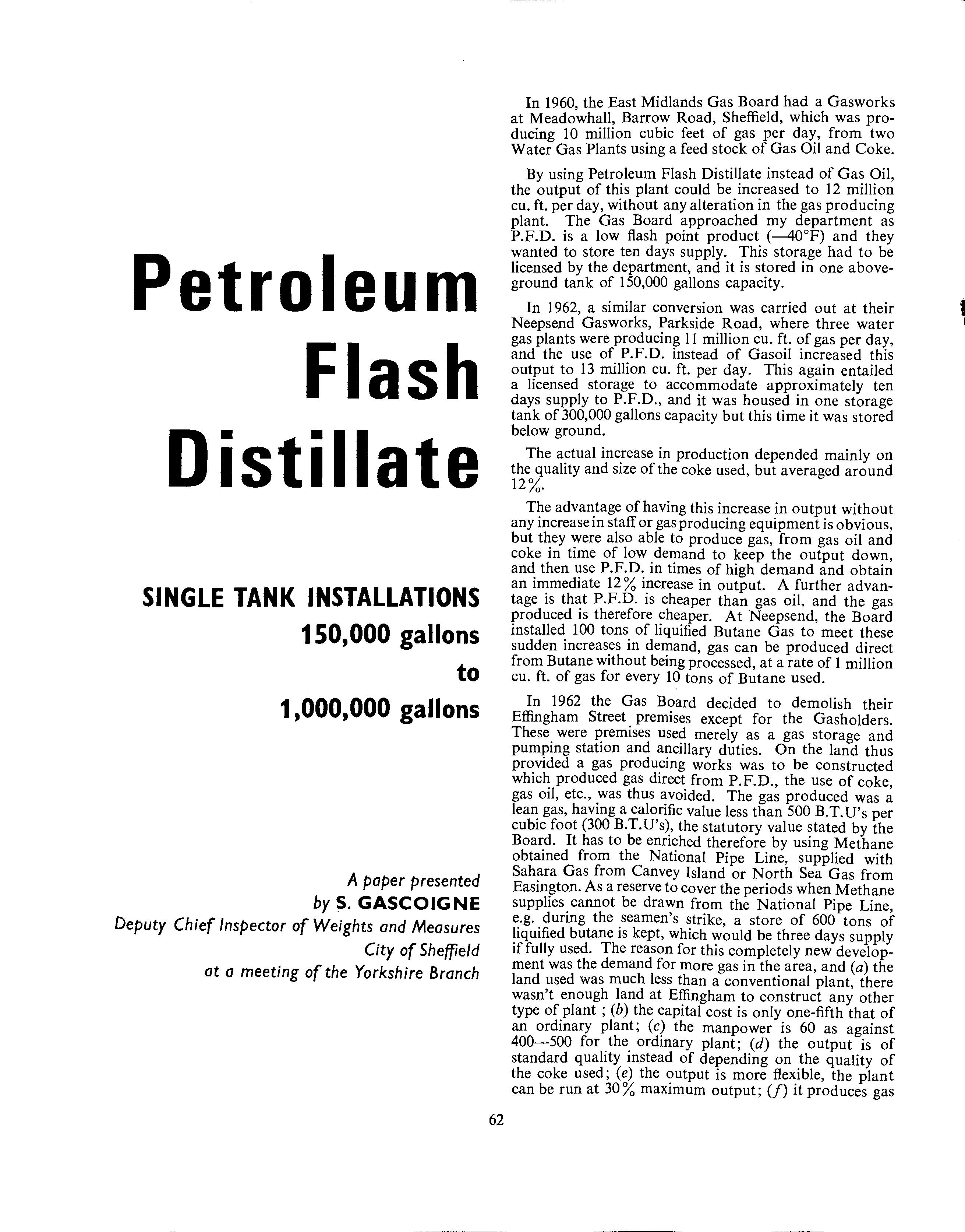
The exc~vating of a hole this size presented some problems, 1t had t? be approximately 75ft. in diameter and 2lft. deep. P1~es had to be driven into the ground around the excavation before work commenced. These were forced into the ground by means of a pneumatic hammer hung from a crane hook which hammered the piles .vertical!Y in~o the wound. The piles are shaped to Joe~ mto their ad~acent pile, and on completion you have a circle ?f steel piles all locked together so that if all the ground is taken from the inside they cannot move. This is alright provided the piles remain a certain depth below the ground at the bottom of the excavation. In this case
when the required depth was reached the ground was just a sea of mud, or slurry which couldn't be moved by an excavator bucket. To overcome this difficulty a further set of piles had to be driven into the ground inside the first set, and men had to go into the excavation and scrape the bottom with buckets and shovels and place the slurry into a large skip on the end of a crane hook which was removed when full. It was a situation many children would have enjoyed, but caused the constructors many headaches. When the work was complete the piles were extracted by reversing the action of the pneumatic hammer which hammered the piles out of the ground. The noise of two of these working together has to be experienced to be believed, and it is a long process as each blow only drives the pile in a fraction of an inch and the piles were at least 30ft. long.
The excavation had to be taken deeper until solid ground was reached which meant that the concrete base was built on top' of a large layer .of concrete ~1erely laid to bring the base back to the required level. This should have been avoided by taking test bore holes, and three were taken, none of which revealed this ground fault. The three were originally placed on the circumference of the tank, but during the planning stage the tank was moved a few feet inside the works, but this small movement meant that only one of the test bore holes came within the new excavation.
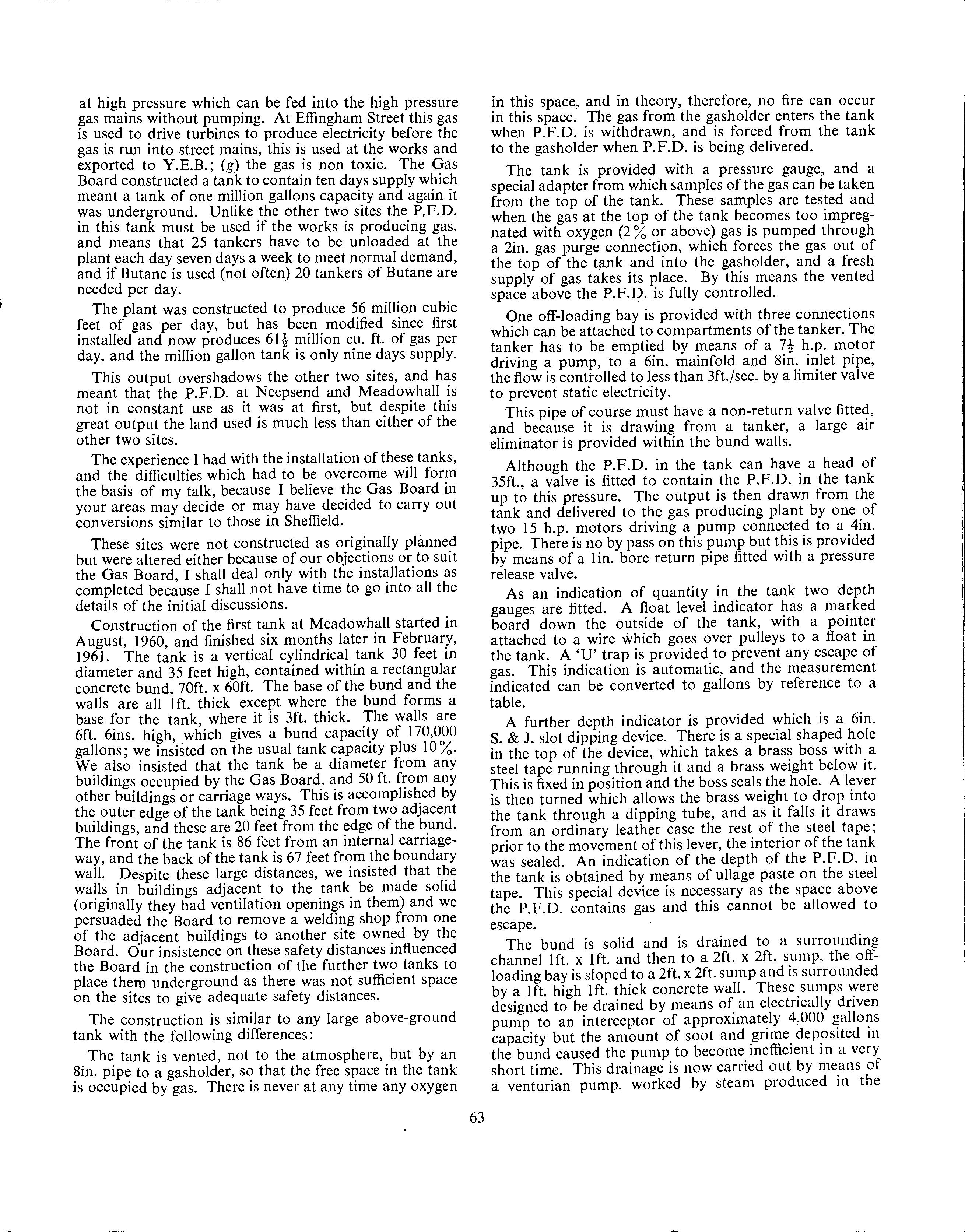
A tank of this size is fabricated on site, the plates of ,i-in. carbon steel are supplied ready cut to shape, and the sides are also bent to form the circumference of the cylinder. The base plates are laid on the concrete base and each plate overlaps its neighbour, and the whole circular base overlaps the cylindrical sides. When these base plates have been laid they are welded together by electric arc welding. The first row of side plates are then fixed and bolted together in a vertical position until a complete circle is made. The bolt holes are already in the plates. Again the plates overlap each o
the~
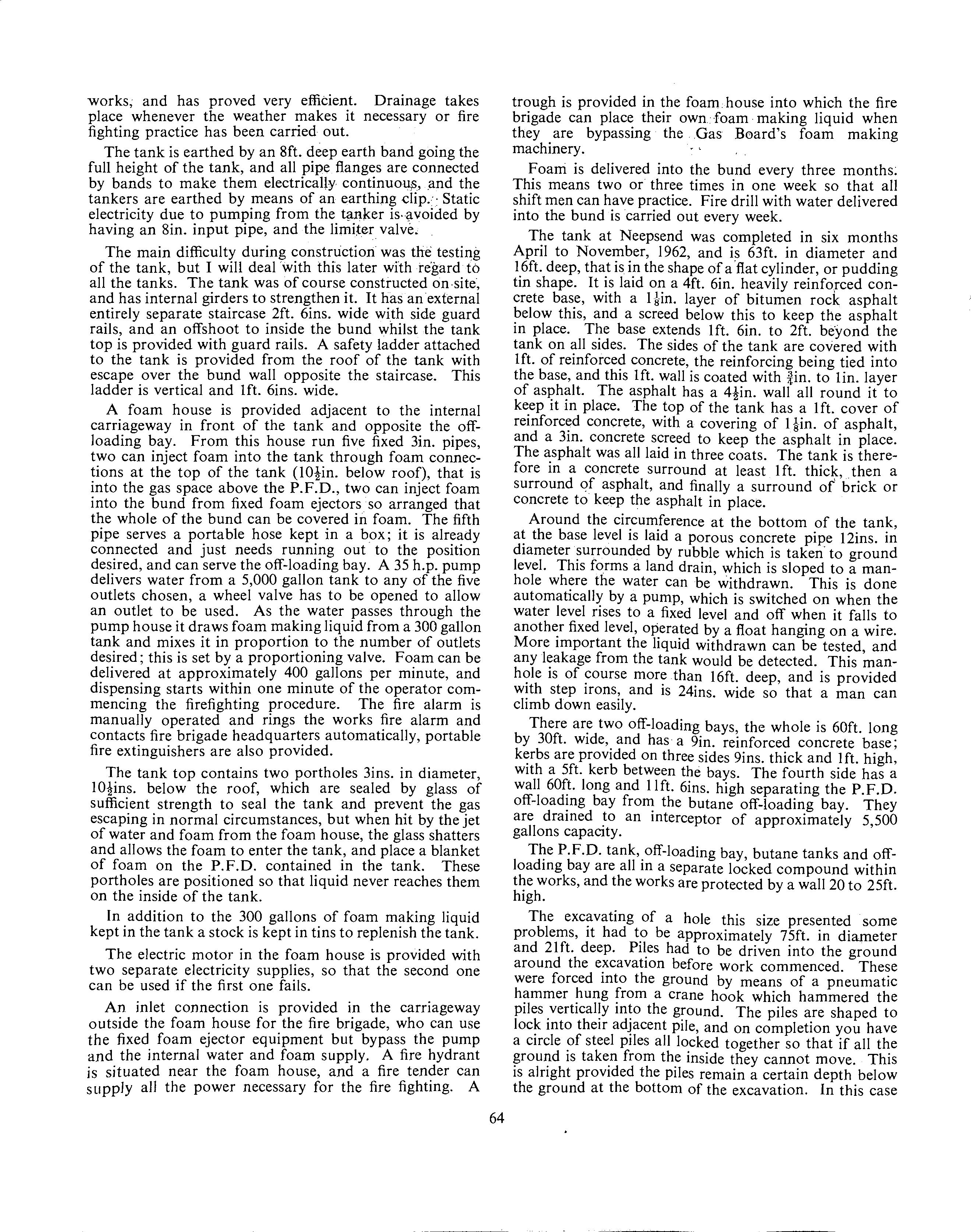
, and are set inside the circle of the base plates. When tl1JS lower layer has been fixed, they are welded to the base plates both inside and outside the tank, and the overlapped plates are welded on the inside and outside. A further layer of side plates are fixed to thjs lower layer by bolts, and overlap the lower layer, and overlap each other. Once this layer has been laid the plates are welded inside and outside the overlaps. This carries on until the top of the tank is reached. In this tank 21 steel pillars are fixed vertically inside the tank, and welded to the base plates, girders are then laid between these pillars until the top of the tank is a series of squares of girders, these girders are originally bolted to the vertical pillars but finally welded. The top plates are then laid on this lattice of girders, they overlap again and are welded inside and outside, and then these plates are welded to the girders. As each stage is built the bolts are removed which held the plates together, and then these holes are welded over, and tills also welds the plates together.
How do we test this tank. It cannot be tested by subjecting it to a pressure of 10 lb. per square inch for 24 hours, for the thrust on the top of the tank would be just in excess of 2 OOO tons a thrust the tank cannot be expected to su~tain. The base of the tank is tested .by means of a vacuum box test. This is a rectangular box with a glass window in the top, the base bas rubber all round it. The box is constructed to be airtight and has two connections at the top. One contains a stop valv_e, and ~he other is connected to an exhaustion pwnp and 1s supplied with a stop valve. Jn practice approximately 2ft. ofwelde_d base is coated with a soap solution. The vacuum box is placed over it, the cock to the exhaust pump left open and the other closed the rubber around the box now forms an airtight fit of' the box to the plate. The air in~ide the box is exhausted by the pump, and none can get mto the box by any other means. If there is a hole in the weld, however, air will be drawn from under the wel? through the soap solution and into the box and bubbles will appear. When exhausted the cock to the exhaust pump is closed and a watch is kept on the 2ft. of weld through the window in the box. If no leak appears, the second cock 1s opened allowing air to enter the box which can then be removed to another portion of weld and the process rep
eate
Tl~e whole of the welds in the base plates were tested 111 this manner, with every other test portion overlapping the previous test portion to ensure that all parts of the bas.e welds were tested. This has to be clone, even though it is a very laborious and exacting process, to clear the base plates from any danger of leaks. If on the second test of filling the tank with liquid, a leak appeared from beneath the tank, you could not possibly know the ~xa~t source of the leak, because the appearance of the hq u1d would depend only on the contour of the concrete base and not the position of the leak. In this case, I witnessed the whole
65
of this test being performed by the makers of the tank, along with a Gas Board employee. This took a complete day, and I was not sorry when the day ended, even though no leak had been revealed. You have to realise that this was done when the tank is completed, so you have to work in a metal dungeon with only the light from a manhole to assist you and an electric hand lamp over the testing box. Entrance being by means of a none too safe wooden ladder.
Ten magnetic crack tests are carried out on the bottom seams, and 10 spot radiographic tests are carried out on the sides. The points where these were done were chosen by myself and a representative of the Board, and the results in every case proved satisfactory. The places were picked where the welding appeared most likely to contain defects.
Once these tests are completed the tank is then filled with water to a height approximately 6ins. below the roof. This means that the tank is subjected to an overload test of at least one-third, as the S.G. of P.F.D. is around .75 (.645 to .73) and the tank would never be filled to this level when in use. This sounds a simple process, but 300,000 gallons of water takes some time to pour into the tank and you have ample opportunity to watch for leaks . as it is being filled. This took about four days to fill. Once full, it is left in this state for some time so you have opportunity of examining the sides for leaks, and I am glad to say none were found. The roof is then tested by subjecting it to a pressure of 24in. water gauge. The tank is sealed and a pressure gauge placed on the roof; in this case and the tank at Meadowhall one gauge you could read direct and another an automatic one which showed the variations in pressure for a period of 24 hours on a circular graph marked with times were fitted. In both these cases the graph was left on for more than 24 hours, around 36 hours, and although the pressure varied it could be compared with the difference in temperatures according to the time of day. This revealed no leaks, but in the case of Neepsend it revealed that the tank top had not been welded correctly to the lattice of girders because the top bowed and bellied and when you walked on it it gave under your feet in parts. This meant the tank had to be unsealed, the tank emptied, the top welded to the lattice of girders and the whole process repeated.
This tank is served by two off-loading bays, which serve one 8in. filling line; there are three hose connections per off-loading bay, which connect to 6in. manifolds. Each bay has a seal pot device or pressure stabilising device, which maintains pressure in these 6in. manifolds at the same pressure as in the tank. A limiter valve is placed in the line to limit the speed of delivery to 3ft./sec. to prevent static electricity.
Venting is again to a gasholder by an 8in. pipe and there is a 2in. purge connection.
There are two pumps serving 3in. supply lines. Now because of the depth of the tank, these have to be submersible pumps driven by 15 h.p. electric motors on top of the tank, but the pump is driven by a shaft inserted in a 14in. square trunking lined with wood, which prevents sparks when the pump is extracted. The pump works at 2,900 revs, and delivers 70 gallons per minute at 75 lb. per sq. in. The pump is an eight-stage pump which means that liquid is passed from one stage to a second stage a little higher in the pump and the pressure is increased; this is repeated eight times to obtain the required pressure and delivery. The pump to do this in one stage could be provided but would be too large to be inserted in the aperture in the tank. The liquid comes up a hollow tube surrounding the drive shaft from the electric motor.
Again there is a lin. bypass pipe for each pump, with appropriate valve.
Another difficulty experienced on .this site was that the tank was within a separate compound within the works, but this site contained only two very large gasholders, the gas producing plant was across Parkwood Road in a separate premises. We allowed the supply pipe to go across this road on a bridge already in existence which carried a 24in. gas main supplying the gas from the plant to the gasholders, and which gave a 24ft. 6in. clearance of the road below. The supply pipe was placed in a sleeve, the sleeve being taken five yards beyond the boundary on either side of the bridge, the bridge rails on one side, and the gas main on the other side form a protection for the pipe. Valves were fitted at each end of the pipe where it entered the sleeve, which are hydraulically operated, so that if a leak occurs there will be a reduction in pressure of oil placed under pressure in an external pipe, then these valves will close automatically. It was thought that the worst that could happen if the bridge was hit, was the deposit of the P.F.D. contained in the pipe on the roadway; the height of the bridge and the protection of the pipe would make fracture unlikely even if the bridge was hit.
Depth indicators on this tank take the form of two 6in. bore S. & J. manually dipping devices, the same as the one described at Meadowhall and one automatic tank device. This works on a float attached to a tape which is wound on a drum within the device, and the portion of the tape approximate to the depth of the P.F.D. is visible through a small window, the exact reading is indicated by a pointer on the window. A pressure gauge with a means of taking samples of the gas in the tank is incorporated in this device. The size of the tank demanded more than one depth indication, and the three are situated at the three corners of a triangle.
The fire fighting equipment is similar to that at Meadowhall, except that no fire protection is provided for the tank, just two fixed foam installations to the off-loading bays and one to a portable hose.
In this case there is a water test of the equipment every month and a foam test every year.
The water tank is of 2,000 gallons capacity and was specially built for this purpose and is a concrete tank on top of the foam house. It is replenished by means of a 6in. water main.
Although this tank is within the works compound, and is underground we insisted that a window in the adjacent building works, which was supposed to provide light to a joiners' shop should be bricked up. The owners of the adjoining property would not agree to this but the glass was replaced by armoured glass.
The Butane tanks at this site and other sites in Sheffield are not licensed by the department, but we supervised their construction if we thought that they would endanger the petroleum storage site. In this case we had a fireproof
66
wall built separating the two sites, which is 60ft. long and l lft. 6ins. high. The tanks are horizontal cylindrical tanks, supported on concrete saddles and the ground is sloped to a catchment pit. There is an automatic spray fire protection to the tanks, and the supply for this comes over the bridge in the road containing the P.F.D. supply pipe.
We also decided on this site and at Effingham Street that once the P.F.D. had gone over the road into the Gas Works it ceased to be stored and we did not supervise the construction of the whole gas producing pipe lines and equipment, etc.
We insisted that the supply pipes on all sites should have a fall from the gas making plant to the tank of at least one inch in ten feet, to prevent any siphoning effects upon the tanks.
The tank at Effingham Stri;:et was commenced in November, 1962, but was not completed until December, 1963. This is not entirely a true statement as the tank was completed and awaiting the rest of the plant's completion before December, I 963.
The construction of the tank was similar to Neepsend in that it was surrounded by a minimum of lft. of concrete, three coats of asphalt which was held in place by bricks or a screed of concrete. The tank was of course much bigger, being similar in shape but IOOft. in diameter and 2lft. ?eep (as against 63 and 16).
The excavation in this case hit rock at a depth far above that originally planned for the base of the tank. As at first planned the tank was to be totally buried in the existing ground, and the supply pipes taken through a tunnel already existing under Sussex Street. When this rock was encountered it was decided to lift the base of the tank so that the top of the tank would be just below Sussex Street ground level but the Effingham Road end would be above ground; the tank would be above ground within the compound. The ground level of the whole area woul~ be raised so that the tank was well below ground at all pomts. This meant that (a) the supply pipes had to be taken over a pipe bridge specially constructed; (b) the outer wall had to become a very strong retaining w~ll, and we insisted that this wall should be taken to a height of 12 feet from either the inside or outside level, whichever was the highest. The tank almost completely occupied a plot of land surrounded on two sides by roads, but on the other two sides by adjoining firms .. T!1e ground had to be rai~ed on these two sides, so the ex1stmg walls were coated with asphalt, a retaining wall built shutting to this asphalt to keep it in position and this wall taken to a height such that it was 12 feet above the level of the adjacent yard level. This meant a very high wall in the P.F.D. compound.
This also meant a very high wall on the Effingham Road side, being 12 feet from internal level but approximately 27 feet from external level.
The size of the tank caused two other alterations to construction, (a) there were two manho~e s to ~he surrounding land drain and porous concrete pipe with two automatic pumps· (b) the input pipe and extraction pipes were taken to a s u~p 13ft. x 3ft. x lft. deep in the middle of the tank below the level of the main base of the tank, so that a liquid seal could be maintained on these pipes with a relative small quantity of P.F.D. contained in this sump, instead of P.F.D. over the whole area of the base; one inch depth of spirit in the main tank contains approximately 4,000 gallons of P.F.D. A similar sump was constructed at Neepsend but was only 3ft. x 3ft. by lft.
Another major departure from previous practice was necessary because of the lack of space in this compound. In this case three off-loading bays were provided and these were situated on top of the tank, on a heavily reinforced raft, but still on top of the tank. The tank therefore bad to be strengthened; the base on which the tank rested had to be also strengthened. The pillars in this tank were 69 in number as against 21 at Neepsend, and although the plates were the same thickness, the girder construction was far heavier and stronger. Each off-loading bay has five hose connections for the tanker and these connect to a IOin. filling line. A spare IOin. filling line is provided. Pressure stabilising devices are also provided, and the bays are drained to an interceptor of approximately 4,000 gallons capacity.
The bridge was specially constructed and acts as a means of escape from the compound by having a walkway over it into the gas works. The headroom is I 8ft. 6in. and warning boards are displayed on outriggers so a large vehicle would hit these first and would be pre-warned before hitting the bridge. It contains five pipes, a 6in. balance pipe to the gasholder, 2in. gas purge pipe ; 2 x 4in. supply pipes, 1 x 4in. recycle pipe, and the electric supply for the pumps. The supply pipes are protected by sleeves and valves at Neepsend.
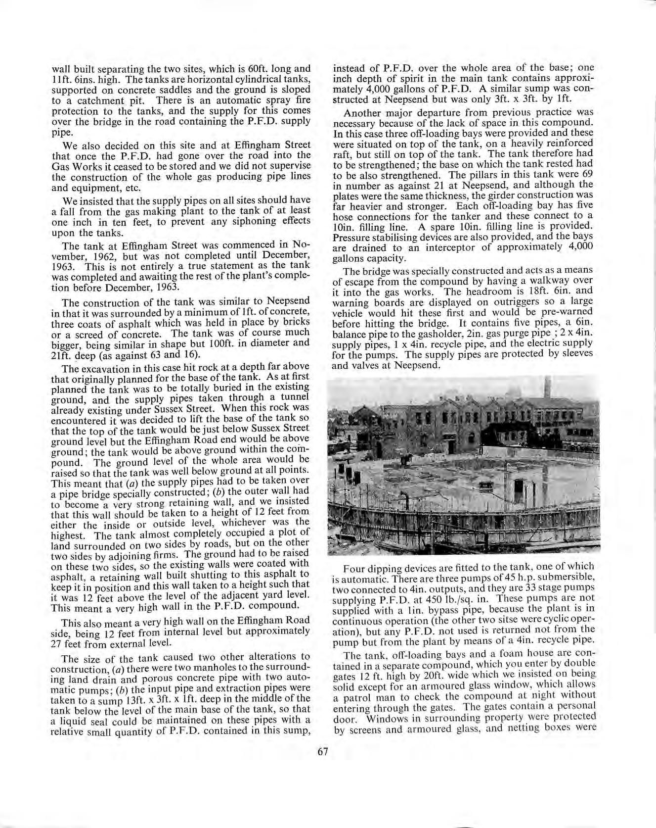
Four dipping devices are fitted to the tank, one of which is automatic. There are three pumps of 45 h. p. submersible, two connected to 4in. outputs, and they are 33 stage pumps supplying P.F.D. at 450 lb./sq. in. These pumps are not supplied with a I in. bypass pipe, because the plant is in continuous operation (the other two sitse were cyclic operation), but any P. F.D. not used is returned not from the pump but from the plant by means of a 4in. recycle pipe. The tank, off-loading bays and a foam house are contained in a separate compound, which you enter by double gates I 2 ft. high by 20ft. wide which we insisted on being solid except for an armoured glass window, which allows a patrol man to check the comp0Lu1d at night without entering through the gates. The gates contain a personal door. Windows in surrounding property were protected by screens and armoured glass, and netting boxes were
67
placed over the windows, which were high to prevent objects being thrown into the compound.
The testing of this tank was similar to the other two, except that when the tank was pressurised the 24 hour test on the tank top was not considered good enough on a tank of this size. The tank was left full of water and pressurised for a long period and the pressure gauge checked, but in the early stages all the seams on top of the tank were tested by means of the application of soap solution, from a brush. This was even a worse job than testing the bottom plates. The weather was fine but the wind played havoc with the soap sunds, and I seemed to live on the tank top for two whole days. We found that the trunking which was made to contain the submersible pumps was lined with wood to prevent sparks when the pumps were extracted. This wood was fastened to the trunking by wood screws, and there was slight leaks from the heads of these screws. This was overcome by welding the screws to the plating of the trunking. I hope they never want the wood lining out, but at least the leaks were stopped. These small leaks were not revealed by the pressure gauge.
This tank was left full and pressurised whilst the concrete walls were constructed; this occupied a very long time, and I regularly, as indeed I did at Neepsend, inspected the plates for leaks on the outside. The advantage of this was that I was able to inspect the plates throughout the whole level of the tank as the staging was raised to erect another section of outer concrete.
Again no protection was provided on the tank. The off-loading bays are, however, provided with an automatic foam producing apparatus. Each off-loading bay has a detector, which upon detecting a rise in temperature above the normal air temperature, allows a reduction in pressure in an air pipe. This triggers off a device in the foam house which allows a weight to drop and puncture the opening of a carbon dioxide cylinder, and allows carbon dioxide under pressure to enter a pressure vessel containing 300 gallons of pre-mixed foam liquid. This foam is then forced out of the vessel along fixed pipes, is aerated and discharges into the appropriate off-loading bay. Each bay has a separate installation, detector and pressurised vessel. There is also a connection through the wall to allow the fire brigade to operate the pipe equipment independently.
When the equipment operates a fire warning is rung at Fire Brigade Headquarters. The works fire warning is operated, an indication is operated in the plant control room and operates an alarm system there.
When Effingham Street was first operated the Methane pipe had not been laid to the works, so that Butane was used to enrich the gas. When the Methane pipe was laid it went to Effingham Street, and also passed the entrance to Neepsend. Whilst the streets were being excavated to take the Methane pipe, the opportunity was taken to lay a 4in. transfer pipe from Effingham Street to Neepsend Gas Works, and valve work and pumps were altered at both sites so that in case of emergency P.F.D. could be transferred from Neepsend to Effingham Street direct from one tank to the other, or vice versa. This pipe caused the department quite a headache as to whether we were responsible for it or not. The idea was that the pipe line should be kept full of P.F.D. and the transfer could be carried out immediately, so the liquid would be dormant in the pipe for long periods and only mobile whilst transferring was taking place. We wrote to the Home Office as to whether this pipe should be licensed or not, and in the meantime we agreed with the Board the safety factors we wanted incorporating in the pipe if it needed to be licensed. The Home Office replied to us when the pipe had been laid that it was not our responsibility and since it has been laid it has never been used. Now it has been disconnected at both ends, and the pipe may be used at some time for transferring gas or other liquids but not P.F.D.
The pipe line was 3,100 yards long and would contain approximately 5,000 gallons of P.F.D.
I am glad to say that no accidents have occurred involving the P.F.D. installations themselves. There have been no accidents of any description at Neepsend and Meadow hall.
At Effingham Street, there was a leak on the gas producing plant which allowed P.F.D. to escape which had been vapourised and heated. As soon as the vapour reached the air it ignited; this fire was estinguished by the Gas Board before the Fire Brigade arrived.
The other accident involved a tanker delivering P.F.D. to the compound, which was parked in Sussex Street and, whilst the driver was going to the doors to gain entrance, the tanker ran away backwards down the road, collided with a second tanker parked across the road, and crashed into the wall. The rear compartment of the tanker was punctured and the P.F.D. ran under the second tanker, and a third tanker just behind this, down the gutter and was ignited by a red lamp left near an excavation in the road. The fire was fierce and destroyed all the tyres on all three tankers, the cab of the second tanker, and partially damaged some of the buildings in the gas works. No further quantities of petrol were involved, and once the fire had been extinguished, the tankers cooled, the wheels on them were replaced and the P.F.D. discharged into the tank in the ordinary way. The plant never stopped operating, and the pipe bridge was not damaged.
To obviate this difficulty, a series of lights have been installed on the outside wall in Effingham Road which tells the tanker driver if an off-loading bay is available, and they do not enter Sussex Street unless one is available and the lights indicate this to them. Tankers do not now arrive in convoys.
Tankers have been known to drive away from the offloading bay before the hoses have been disconnected, and sometimes before the hoses have been drained. This is now prevented by a notice on a long arm dropping in front of the driver's cab, completely obliterating his view and stating do not drive away until hoses disconnected. This arm operates like the arm to some types of railway crossings, or the gateways to Army camps. It is moved out of the way by the Gas Board employee when all hoses are disconnected and drained.
No fires have been caused by driving away with the hoses attached, but it has meant the purchase of new hoses, and some spillage of P.F.D.
All these accidents have been away from the Licensed Installation, and I am pleased to say that all three licensed premises have been accident free since they have been in operation.
68


