ç
PS1: TERRACED HOUSE LULU: LANDSCAPE + URBANISM ANNA REZIN STUDENT ID:19000358
CONTENTS
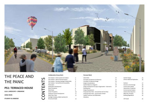
THE PEACE AND THE PANIC
Collaborative Group Work Site Analysis - Street sections & Analysis Site Analysis - Open & Disused spaces Site Analysis - Housing Typology & Materiality Site Analysis - Connectivity & Accessibility Masterplan Masterplan Development Block Precedents Block Rules Street Precedents Pedestrian Street Development Block Floor Plans Sunlight Analysis, Block sections & Structural loads
Personal Work 2 3 4 5 6 7 8 9 10 11 12 13
Client Brief Principles Of Japanese Architecture Principles Of Japanese Design Design Considerations Spatial Adjacency Diagrams Design Development & Space Organisation - Volumetric Development Design Development Proposed Floor Plans - Ground Floor & First Floor Proposed Floor Plans - Second Floor & Roof Faççade Treatment and Materiality Elevations
14 15 16 17 18 19 20 21 22 23 24
Garden Design Interior Material Exploration
25 26
Sections Structure and Drainage Construction Details Axonometric Projection Environmental Analysis Construction Sequence RIBA Plan Of Works Building Regulations
27 28 29 30 31 32 33 34
3D Visuals
35
SITE ANALYSIS Street Sections & Analysis
D
B
C
C
D
B
A
A
Section AA - Mercian Way
Section BB - Worrall Street
South of Edgeley has many dead end streets making the link to the high street poor.
Public Semi-public Semi-private and Private
Section CC - Hardcastle Road
Majority of the streets are overcrowded with vehicles parked on either side of the street.
The residential area surrounding Stockport FC stadium has been separated by a large busy road, Mercian Way. Beyond this is the high street with all the local facilities. During our site visit we analysed a few of the streets where the main concern highlighted that Mercian Way acts as a boundary where the residential area (South) lacks from accessing these facilities. On these residential streets we noticed several problems with parking facilities and bin storage making the narrow streets seem tight and constantly busy where traffic would have to wait. Furthermore, there are only a few secondary streets that connect to the main road. The remaining streets are no-through streets which seems fairly inconvenient for residents turning their vehicles, parking and being able to access Mercian Way. With almost all the residential house, the use of a front garden was a popular aspect, and this allowed residents to access the front of the house but also use the space for outdoor plants or storage.
0
10m
There is not enough parking space on the streets therefore, residents have parked their cars on yellow lines.
Section DD - Duchy Street
Insufficient bin storage leading to residents leaving their bins at the front of the house.
2
SITE ANALYSIS Open and Disused Spaces
Green Spaces
Disused Spaces
9 3
1
2
7
Located opposite our proposed redevelopment is a demolished station building, resulting in a large open space left in disrepair. This leaves the site open to vandalism being located next to the railway line itself and hidden pedestrian footpath. With our proposed buildings positioned to take advantage of the reservoir view this becomes an eyesore.
3
4
8
A large overgrown area on the bank of the reservoir creates an unsightly appearance and furthermore restricts existing houses from reservoir views. This disused space would detract from the beauty and views of our proposed development being located directly opposite. This area would benefit from a usable green space to attract locals.
5
6
9
Currently a large open space exists next Stockport’s football stadium, previously used as car parking. This site remains level for easy development and has quick and easy access to main road links.
6
2
1 4
10 7 5
8
In close proximity to the site, there are a few small pockets of green spaces, however, only Alexandra Park is used often. This is perhaps because of the facilities the park offers such as a play area, skate park and seating. Around the residential area there are a lot of trees, shrubs and bushes mainly used to block out noise from the train lines and the vehicles on the main road. In addition, to this the reservoir is also surrounded by greenery, which makes it a pleasant space when walking past. It will be great to consider the potentials of what smaller green spaces can offer to the residential area when considering the masterplan proposal.
10
On the edge of the reservoir located opposite our proposed redevelopment is an overgrown and unkept area of land. This has left the site open to antisocial behaviour and homeless living, creating an undesirable area for locals. With our proposed buildings positioned to take advantage of the reservoir view this becomes an eyesore and would benefit greatly from development to a green space.
3
SITE ANALYSIS Housing Typology and Materiality
Residential Map
Residential Styles
Residential Rail Details
Residential Door Details
1
2
3 4
3
5
6
2 1
4
Residential Building Details
5
The residential houses located in Edgeley are mainly terraced with a few semi-detached where the primary material used is red brick. What look like old Victorian terraced houses, they have various special features ranging from an arched doorway emphasised by the arrangement of the bricks to the use of coloured brick. Each of houses on the streets share something in common giving an specific identity to that particular street.
6
When moving forward in our projects, this feature and consistency is something that we wish to consider. Whether that is through the use of materiality, certain entrance or aperture aspect.
4
SITE ANALYSIS Connectivity and Accessibility
Building Uses
Infrastructure Links
Trains to: Manchester Piccadilly Liverpool Blackpool
Edgeley Park
N
Movement around the site Buses to: Stockport
Buses to: Stockport
Castle Street (Commercial Use)
Edgeley Park
N
Side Paths linking the main streets
High Street - Castle St Buses to: Wythenshawe Altincham
Reservoir Trains to: Manchester Airport London Buxton
St Matthews Church (Religious Building)
Stockport Train Station Stockport Area Alexandra Park Bus Stops Site
Access by Walking 18 Minutes
Edgeley Park Stadium (Sports) Edgeley is one of the Metropolitan Borough of Stockport’s most overlooked suburbs, despite housing a high quality football team. It also has a “Shopping Centre”, which is the Castle Street. Edgeley Shopping Centre is the heart of our community. Most of the local population attend the St Matthews Church on Sundays in the Grenville Street. The church also hosts a mixture of worship styles and holiday activities for children on Saturdays.
10 Minutes
6 Minutes 3 Minutes
Access by Car 7 Minutes
5 Minutes 3 Minutes
All local facilities such as the train station, high street, the reservoir are quite close and accessible by walking or by car. There are several bus stops located near the high street and on Mercian Way which can take residents and visitors to different areas of Stockport as well as other close towns nearby. Trains passing through Stockport train station allow people to travel to Manchester, London, Liverpool and many other cities. Overall, Edgeley has great transport links and facilities which are all in close proximity.
5
MASTERPLAN
Proposed Masterplan
Masterplan Masterclass Primary Road Secondary Road Tertiary Road
(NTS) Residential Use Commercial Use Educational Facilities Religious Buildings Sports / Recreational / Other
(NTS) Masterplanning Workshop Group plan - Perimeter Block - Court - Muse
(NTS) The Masterplanning class enabled us to produce a figure ground plan, allowing us to determine primary, secondary and tertiary roads around the existing site. Secondly we identified the existing building typology. In groups, we then produced a proposed masterplan.
1:2000 @ A2 The finalised masterplan can be seen above, including all four groups proposed blocks and adjoining roads. The masterplan incorporates a green link with specifically designed sections to address each blocks design style. This road links all blocks to one another and to the reservoir.
6
MASTERPLAN DEVELOPMENT Together as a whole group we have developed a new masterplan proposal for Edgeley. We have introduced many different aspects such as green infrastructure links, commercial and residential typologies as well as improving the existing green/open spaces, streets and roads.
Wind and Sun Analysis
Summer Sun Path
Varying Typologies
Winter Sun Path
Prevailing wind from South-west.
Terraced housing
Green Infrastructure
Pockets of green open spaces bringing the community together.
4-6 storey high apartments.
Pavilion blocks adjacent to reservoir.
Mixed-use commercial and residential
Access and Connectivity
Parks / Green areas
Green link corridor connecting Alexandra Park and New proposed park
Connecting Edgeley to wider Stockport (East and West)
Connecting residential area to high street (North and South)
Green link connecting parks
7
BLOCK PRECEDENTS Nieuw Leyden by MDRDV in Leiden, Netherlands Trent Basin in Nottingham designed by Sarah Wigglesworth Architects Terrace housing proposal in Dundashill, Glasgow designed by JM architects, McGinlay Bell, Ann Nisbet Studio, MAST Architects, HAUS Architects, Stallan brand
NIEUW LEYDEN
Undercroft parking with clear design rules for the master plan.
by MDRDV
Buildings should be made with one clear material and the quality of that material must be used on all 4 sides.
Client: Nieuw Leyden CV Location: Leiden, Netherlands MVRDV designed an urban plan of 670 dwellings. The urban plan gives strict parameters to ensure the relative cohesion of the urban grid whilst maintaining enough flexibility for consumer driven developments.
Variegated build line with clear build rules for the block and the corner plots.
TRENT BASIN 2nd x m
by Sarah Wigglesworth Architects
Maintaining coherence of a two and three Story high building, with a set floor to floor height.
1st x m
Client: Blueprint Location: Nottingham
GF x m
The scheme centres around its public realm, walkways and a new public square overlooking the River Trent, combining city life with waterside living, each home, footpath and open space.
To introduce brick element or feature into design visually connecting the street and to fit in surrounding context.
DUNDASHILL, GLASGOW
A range of roof designs shown reflects creativity and difference in the collaborative projects, the type of roof design was not limited
by JM Architects, McGinlay Bell, Ann Nisbet Studio, MAST Architects, HAUS Architects, Stallan brand Client: Igloo Regeneration Location: Dundashill, Glasgow
Flexible garden space in front of building line to create a sense of ownership and privacy for the building
The proposal was for a custom build housing solution for the Dundashill area to design a terrace house for a proposed development.
Garden fence
8
BLOCK RULES & DEVELOPMENT Various block strategies that we have considered to allow flexibility to suit residential needs.
Residential Parking
Block Rules Ground floor residential parking at rear of house accessed via a small private road.
m
36
80m
Household Waste - Bin Route Bin route as shown in diagram to access communal bins store located on the ground floor which can be accessed by residents through this internal passage.
8m
1. X4 Corner plot typologies
Terrace Personalisation
3. All plots should be 3 storeys high
5. Private garden located and accessed via first floor.
The block has been designed to allow some coherence with maximum amount of flexibility in order to suit client’s requirements. Personalised Frontage Extension at rear
7077.5 mm
2. X14 in-between typologies
4. Maximum and minimum building lines as shown above.
6. All plots should feature some element of brick and follow brick dimensions.
9
STREET PRECEDENTS Precedent landscapes St Andrews, Bromeley - by - bow, London Holland Park Villas, Royal bourough of kensington and chealsea Building with Rock and on the Rock, Salzburg, Austria
ST ANDREWS, BROMELEY-BY-BOW, LONDON
Distinct areas of green space connected by green links.
by Townshend Landscape Architects A key aim of the landscape proposals was to create a green network of public and semi-private open spaces to help to break down the scale of the buildings within a high density environment. The intention was to create a neighbourhood feel around a series of green playable streets and communal courtyard spaces. The main public spaces are St Andrews Gardens to the West and Reeves Park in the northern part of the site.
Organic landscaped green spaces with multi height vegetation in a meadow style.
HOLLAND PARK VILLAS, ROYAL BOROUGH OF KENSINGTON AND CHELSEA
Sweeping walkways located close to other green spaces and incorporate water within the design.
by Gillespies Landscape Architects The aim was to create luxurious private and communal gardens for the residents. Driven by the proximity and natural beauty of neighbouring Holland Park, the landscape design draws in the woodland understory, creating a setting for the existing perimeter trees on site and embedding the new buildings within this very sensitive site, with the woodland and natural landscape imposing itself onto the architecture.
BUILDING WITH ROCK AND ON THE ROCK
Rectangular landscaped area with lush vegetation.
Meadow Style planting, with cobbled paving.
by Karin Standler Landscape Architecture The transition from public to private open space is drafted as miniature landscape. Boulders with different heights are used for visual protection for the private open space. The miniaturised rock landscape separates the residential buildings from the public space. Passers-by stroll along these miniature landscapes, while residents are able to enjoy their private spheres behind them.
Organic landscaped green spaces with multi height vegetation in a meadow style.
10
PEDESTRIAN STREET DEVELOPMENT SuDS Strategy
Street Plan
Street Paving
Organic shape to replicate Reservoir
Road/Crossing
Tactile Paving
Journey along the street
Materiality & Planting Adjacent to our block is a pedestrianised street that links the residential area to Castle street and the Reservoir.
Building Line 1
Tactile Paving
Building Line 2
Building Line 3
We have developed a street strategy that allows the concept of a journey which residents can enjoy when walking towards the Reservoir. This has been applied using the idea of SuDS which are proposed in an organic shape to replicate the reservoir. Pampus Grass
Mature Trees
Medow planting
Medium Shrubs
Manage runoff volumes and flow rates from hard surfaces, reducing the impact of urbanisation on flooding Provide opportunities for using runoff where it falls Protect or enhance water quality (reducing pollution from runoff) Protect natural flow regimes in watercourses Are sympathetic to the environment and the needs of the local community Provide an attractive habitat for wildlife in urban watercourses Encourage natural groundwater/aquifer recharge (where appropriate) Create better places to live, work and play.
• • • • • • •
1 2 3 4 5
Vegetation Pervious Membrane 200mm Wide granular backfill Facebrick 75mm Diameter sleeved weep holes
6 Aco Drain 7 Concrete foundation 900mmx225mm 8 Vertical brick detail 9 50mm gravel base 10 Earth/Soil 11 Flat Cobble stones
Threshold Paving Slab 100 x 100 mm
PRODUCED BY AN AUTODESK STUDENT VERSION
Organic Landscaped SuDS
Street Paving Slab 210 x 210 mm
Street Furniture
1 2 3
8
4 5
6
9 7
11 10
PRODUCED BY AN AUTODESK STUDENT VERSION
Key
ODUCED BY AN AUTODESK STUDENT VERSION
•
Street Paving
Threshold
SuDS are more sustainable than traditional drainage methods because they:
11
BLOCK FLOOR PLANS Grond and First Floor Plans 1:500 @ A3
PRODUCED BY AN AUTODESK STUDENT First Floor Block Plan Ground Floor Block Plan
0
5m
10m
25m
50m scale 1:500
12
SUNLIGHT ANALYSIS, BLOCK SECTIONS & STRUCTURAL LOADS Further development which considers sunlight and how the orientation of the block affects our individual plots, mainly the garden spaces at rear and the pedestrianised street. Solar Analysis (Summer)
Solar Analysis (Winter)
07:00
07:00 W
Structural Strategy
W
20:22
N
N 17:12
07:00
05:09
21 June
S
S
07:00 08:12
E
E
21 December
Large amount of shading towards the rear of our plots where most of the gardens are shaded due to the heights of the roofs.
Long shadows towards North-west of the block, however, frontages remain clear of any dark spaces allowing the morning daylight to brighten the space.
12:00
12:00 W 12:00
Acknowledging structure is essential during the early design processes due to the substantial raised gardens requiring deep structure. This will be achieved through columns or wall separations between dwellings, minimising the span to 6m whilst the house wall takes the remaining load. This structure allows for the carport/garden structure to be different to the dwelling construction, meaning a lighter more compact structure can be utilised.
The structural elements taking the garden roof load can be tailored to the individuals design. Designs can range from a simple post to a full wall to wall perforations making each section unique to the individuals construction and architectural design. Public Semi-public Semi-private and Private
Proposed Street Sections
W
20:22
N
N 17:12
12:00
05:09
21 June
S
S
08:11
E
E
20 December
Shadows created only from the plots which have been set back, otherwise, spaces are well-lit. 16:00
16:00 W
Both rear of our plots and frontages are within the shaded areas with very little garden space in sunlight. Section AA - Corner Plots (NTS)
16:00 W
20:22
N
N
16:00 17:12
05:09
20 June
S
S
E
08:11
20 December
Pedestrianised street and frontages are shaded by plots whereas garden spaces have little to no shadows.
E
Long shadows created by the sun towards the front and back of block.
Section BB - In-between Plots (NTS)
13
CLIENT BRIEF
Daily Activity Tatami Room
Family Profiles
Bed Quiet Space Tatami Room Morning Bed Quiet Space Tatami Room Bed Quiet Space
Option being taken forward Precedent Study
Brief
Shower Bathroom Water Shower Vennlaaon Bathroom Water Shower Vennlaaon Bathroom Water Vennlaaon
Fridge Freezer Cooker Fridge Oven Freezer Vennlaaon Cooker Fridge Oven Freezer Vennlaaon Cooker Oven Vennlaaon
Bathroom Mirror Table Breakfast Bar Water Bathroom sink Mirror Table Bathroom Breakfast Bar Water sink Mirror Table Breakfast Bar Water sink
Quiet Space Seaang Tatami Room Quiet Space Seaang TatamiSpace Room Quiet Seaang Tatami Room
Toilet Vennlaaon Water Toilet Vennlaaon Water Toilet Vennlaaon Water
Afternoon
Having recently migrated from city life in Japan, a young couple in their early 30’s, along with their young son, have decided to settle in Edgeley after a recent job opportunity. The father will be working in Manchester city centre Monday-Friday and will therefore commute via public transport but will cycle to the station daily, therefore there is a necessity for cycle storage. Having a young child, the mother mainly looks after him during the day meaning its essential to have a car and therefore a place to park with easy access to the house to ease of unloading shopping etc. The family are keen to keep the mothers Japanese heritage alive, but desire to move away from traditional Japanese architecture in search of minimalist modern designs introducing more English culture while keeping in touch with Japanese materiality and design principles. To maintain their current home patterns of daily life it is essential for the design to include a Tatami room, easy transition between the indoor and natural world while maintaining privacy in the comfort of their home. The family will occasionally have family members and friends stay while visiting the UK.
Evening
Family Profiles Father
Mother
Name: Sara Nationality: Japanese Age: 32
Grew up in Kyoto Japan, Graduated, Moved to Tokyo, Married current husband, had son, Moved to UK.
Grew up in London, Graduated, Moved to Tokyo, Married current Wife, had son, Moved back to UK.
Needs: Privacy, Quiet Environment, connection to outdoors, big Kitchen, spiritual Room.
Needs: Connection to outdoors, space for visitors, garden, contemporary house.
Needs: Space to play, vironment, Connection doors, independence,
Loves: Spending Walking/cycling, laxation, music,
Loves: Spending time with son, cycling, quiet time/relaxation, playing guitar/games, socialising, cooking.
Loves: Spending time with parents, Walking/ cycling, quiet time, music, dancing, animals.
time with son, quiet time/reanimals, cooking. Name: Adam Nationality: English Age: 33
Hates: Loud noise, enclosed spaces.
01:00
02:00
03:00
04:00
Ambitious, Control, Enthusiastic
05:00
06:00
07:00
08:00
09:00
10:00
11:00
12:00
13:00
Quiet Ento outsocialise.
Morning Hates: Loud noise, busy environments. Morning MorningUsers:
Users:
Traditional, Safety.
00:00
Grew up in Tokyo Japan, Lives happily with both parents of differing cultures, Moved to UK.
Name: Sora Nationality: English/Japanese Age: 3
Hates: Crowded spaces, narrow corridors, noise.
Users:
Daily Ritual
Son
Creative, Adventurous.
14:00
15:00
16:00
17:00
18:00
19:00
20:00
21:00
22:00
23:00
Father Mother Child
14
UUlity Wash mach UUlity Wash mach UUlity Wash mach
PRINCIPLES OF JAPANESE ARCHITECTURE
Precedent: Gosize
Japanese Architecture and Precedent
Specific Japanese Design Principles Utilised In House Design Fukinsei
Kanso
- Asymmetry or irregularity.
- Harmonising yourself with your surrounding environment.
-Controlling balance.
-Simplicity - elimination of clutter.
-Nature itself is asymmetrical yet balanced.
-Plain, simple and natural manner. -Mindfulness of your furniture.
-Seamless transition to outdoor environment -Close connection to outdoors
Yugen
Shibui/Shibumi
- The deep sense of mystery, hidden beauty, darkness and depth.
- Sense of simple, subtle, and unobtrusive beauty.
- Characteristics present in Japanese aesthetics.
- Beautiful by being understated. - Simple design and material choice.
- It represents something - subtly suggested.
The Japanese based architecture firm, Gosize, designed this rectilinear home/studio featuring large openings with views of the serene natural setting connecting the internal and external environments seamlessly. Its interior is centred around a small courtyard with a pond. “Seeking to reflect a distinctive Japanese aesthetic that favours natural materials and finds beauty in simplicity, the design emphasizes plainness and blank spaces in the interior,” explains Fujita the lead designer. The exterior again utilises natural materials in the form of natural stone to blend in to the natural environment with a compacted dirt floor internally. https://www.dezeen.com/2019/09/26/f-residence-gosize-concrete-house-office-hyogo-japan/
Shizen - Naturalness. - An absence of pre-tense or artificiality. - Creating a natural-feeling environment. - Purpose and intention.
- Strong connection to nature. Seijaku - Tranquillity or an energized calm. - (quite), stillness, solitude. - Japanese Zen garden.
-Simplicity -Natural Materials -Surprise Element on entry
-Close connection to nature -Natural Materials -External/Internal courtyard
https://www.presentationzen.com/presentationzen/2009/09/exposing-ourselves-to-traditional-japanese-aesthetic-ideas-notions-that-may-seem-quite-foreignto-most-of-us-is-a-goo.html
-Opaque walls resemble Washi screens -Allows for diffused natural light
15
PRINCIPLES OF JAPANESE DESIGN
Precedent: Carlo Scarpa
Principles of Japanese design and Precedent Study
Specific Japanese Design Principles Utilised In House Design Datsuzoku
Tatami room
- Freedom from habit or conventional.
- Flooring covered with woven rush.
- Escape from daily routine.
- Distinct smell.
- Made with the raw materials of nature.
- Tokonoma - ornamental alcove set slightly above floor level used to display a variety of objects including ornaments, trophies, flowers.
- Many surprises await at almost every turn in a Japanese Garden.
- Tea Ritual/Sleeping space.
Timber slatted window/door covering
Entrance Hall
- Obscure the views from outside in.
Carlo Scarpa was well known for his largely Japanese influenced designs. Scarpa established himself through the use of old techniques in Japanese architecture and transform this into modern a interpretation. His attention to weight, thickness, line and mass influenced materiality and structure. The influence of water, light and levels have allowed control over the space along with lighting and shading.
The top left image displays a modern interpretation of a traditional slatted window/door detail. This is an element I’m particularly interested in carrying forward within my design used partially to increase privacy, add an element of tradition as well as creating interesting lighting features within internal spaces.
- Step acts as a barrier between indoor and outdoor environments.
- This technique allows for good ventilation throughout the year.
- Footwear removed at lower level and placed in a cupboard.
To the left is an example of a tranquil space showing a surprise element on approach. The simplicity of this space is what makes it. ‘Less is more’.
Materials
Bathing Ritual
- Presence of wood.
- Japanese homes have their own furo, used only for soaking.
Concealing internal spaces externally is a feature I would like to carry forward. This allows for the element of surprise whilst exploring the building, ‘what’s perceived on the outside isn’t always as it seems’. The significance of lighting produced by window placement and design is an interesting technique I would like to explore further.
Th
re s
- Wood is preferred as a finishing material not being concealed by paint or other coatings. - It was used in its natural form so that the grain could be appreciated.
ho
ld
- A separate room for soaping is essential usually containing a showerhead. - It is essential that the bath and toilet are kept separate.
Sliding Doors - Translucent screens allow for the division of rooms. - Screens allow for transition and change within spaces. - Translucent allows for diffused light.
https://www.presentationzen.com/presentationzen/2009/09/exposing-ourselves-to-traditional-japanese-aesthetic-ideas-notions-that-may-seem-quite-foreignto-most-of-us-is-a-goo.html
https://www.wallpaper.com/architecture/carlo-scarpa-japanese-influences-explored-at-the-maxxi-foundation-in-rome
16
DESIGN CONSIDERATIONS Building Considerations
Building Parameters
2 Storey/3 Storey Shading analysis Extending the building back may give valuable garden storage or increased room size but will block views to the green link and stop the wrap around garden layout.
Ground Floor Max 1400mm
Extend Sideways to gain space for a more desirable room size ensuring enough space for exiting car.
Max 2500mm
Extend to the rear on ground floor only, making sure to leave adequate space for parking.
Max 1000mm
Creating 360 Degree Views Ground
First Floor Max 1400mm Max 1000mm Max 630mm
Extend Sideways to gain space for a more desirable room size.
Max 630mm
Summer
Extending forward may create an awkward flow for pedestrians.
Summer
First
Shading Consideration Areas towards the rear should be kept as open as possible due to the nature of the underground conditions restricting natural light. Alternativey create a void or lightwell.
Winter With my proposed plot being located on a busy intersection to a fully pedestrianised street, it is important to create an active frontage on two sides of the building being the gateway in to the road. The need to address both sides whilst maintaining privacy and unique building designs is of great importance, yet allowing views on to green link and green pedestrian route from within the living spaces. First Floor Plan First Floor Plan PRODUCED BY AN AUTODESK STUDENT VERSION
1m
2.5m
0
5m
0.5m
1m
2.5m
scale 1:50
The way in which you enter the building defines the spaces drastically along side the thin space towards the rear. Due to the position of this space, the entrance is forced to the left side of the building in turn reducing the active frontage and views to the street meanwhile creating a long unusable corridor. On the other hand by placing the entrance to the side allows for a shorter much wider circulation space and allows activity on the front side of the building. PRODUCED BY AN AUTODESK STUDENT VERSION
PRODUCED BY AN AUTODESK STUDENT VERSION
Vehicular
PRODUCED BY AN AUTODESK STUDENT VERSION
The long corridor forces important rooms to the side and back of the plot restricting views and windows. Whilst the side entrance allows much wider rooms at the front able then to wrap around the front and side of the plot giving a better sense of security and active frontage.
Entrance Position determining layout
Separating Living spaces over the different floors allows for constant 360 degree views in communal spaces. This allows views of differing garden types/styles throughout the house creating unique spaces where each room produces avery different experience. This also creates a good sense of security.
Poor spatial arrangement Good Spatial arrangement
17 PRODUCED BY AN AUTODESK STUDENT VERSION
PRODUCED BY AN AUTODESK STUDENT VERSION
Pedestrian
Second
5m scale 1:50
PRODUCED BY AN AUTODESK STUDENT VERSION
0.5m
N
N
0
Looking into the effects of building height and lighting levels was very important in determining how many floors could be utilised in the extension at the rear. Three storeys shows increased over shading during winter and summer. Two storeys also shows a large amount of over shading in winter but summer shows very little. As lighting is an important factor in my design the decision was made to focus on two storeys.
PRODUCED BY AN AUTODESK STUDENT VERSION
Site Access and Movement
Winter
SPATIAL ADJACENCY DIAGRAMS House Layout Configuration
Option 1
Option 2 Breakfast Seating/ Bar Table Bed
Garden
Bedroom
Tatami Room TV Seating
Storage
Living
Table
Landing Bathroom
Stor-
Chairs
Kitchen
Dining
Hob/ Oven
Fridge/ Freezer
Stairs
Study Area
Desk Chairs
Extractor
Breakfast Bar Seating/ Sink Table Chairs
Storage
Bike Store Washing Carport Machine
Shoe Store
Garden Table
Storage
Circulation
B/S
Toilet Sink Mirror
Sink
Utility WC
Entrance Lowered door step
Storage Shelving
Desk
Tatami Room
Study Area Storage
Kitchen
Dining
Landing
Chairs
Bedroom
Shelving Bed
Storage Carport
Washing Storage Machine
Entrance
Storage
Bedroom
Living
Seating Mirror Storage
WC
Utility
Circulation
Sink
Storage
Extractor Bike Store
Fridge/ Freezer
Stairs
B/S Bathroom Toilet
Hob/ Oven
TV
Bed
Lowered door step
Shoe Store
Storage
Accvity Activity
Furniture Furniture
Sleeping
Bed Tatami mat
Toilet
Toilet Sink
Shower/ Bathing
Shower
Brush Teeth
Sink Mirror
Dress/ changing
Wardrobe Mirror
Reading/ Study
Desk/chair Books/shelvesMusic Tatami mat
Lighting
Eating
Table/Chairs Talking Breakfast Bar
Lighting
Noise
Music/ Guitar
Guitar Storage
Lighting
Noise Vibrations
Lighting No Lighting
Noise
Visual Privacy
Sound
Lighting
Heat Smell Vapour
Watching TV Make-up Cooking
Option 1: Shows the Carport with bike storage connecting to the circulation space via the utility room. Utility room also contains the ground floor WC. Also on Ground floor is the open plan kitchen/Dining for ease of carrying shopping and waste through car port. Study area shown in circulation space along with entrance hall. On First floor all linked to stairwell and landing is the living room, tatami room, toilet room, shower and bedroom mostly all linking to garden spaces. On second floor are bedrooms linking to garden and bathroom.
Circulation Space Stairwell Living Room Bathroom
Option 1
Option 2: Shows the Carport with bike storage connecting to the circulation space via the utility room. Utility room also contains the ground floor WC. Ground floor contains the living room to produce an active frontage and guest bedroom. First floor contains study area, tatami room, open plan kitchen/dining which all have garden views and an element of privacy from the outside world being raised, toilet room and shower room are also located on this floor. Second floor contain 2 bedrooms linking to garden and bathroom.
Option 2
Option 1: Second floor allows for two decent sized bedrooms to have garden views and privacy being set back. Family bathroom and circulation space with possible void to 1st floor with views to the back garden.
Bedroom Tatami Room Kitchen Dining Cycle Storage Carport
Option 1: First floor allows for Living room and bedroom to have garden access and privacy. Tatami room separated for quiet and garden connection. Bathroom in central location away from important rooms.
Comparable accvity Compatible Activities
Senses Input/Output Senses Inputs/Out-
Produce Produce
Visual Privacy Silence
Snoring
Reading
Visual Privacy Lighting
Sound Smell
Music/Singing
Visual Privacy Lighting
Sound Moisture
Lighting
Noise
Visual Privacy Lighting
Noise
Music Singing
Singing
TV Eating Seating Talking Coffee table Music Mirror TV Storage Singing Hob/Oven TV Sink Music Surface Talking
Gardening
Storage Water
Laundry
Washing machine
Noise
Cleaning/ Hoover
Storage Vacuum
Noise
Option 1
Music
There was great desire to incoorperate communal areas over two floors enabling full use of the entire building. This creates garden spaces with connections to the outdoors on all floors with 360 degree views and windows in every room. The spead of activities over different floors creates an active front to the street with key rooms being to the front and side. There is need for private spaces within the building to restrict noise to those rooms in need e.g bedrooms therefore making the 3rd floor fully private.
Study Area Entrance Hall Storage Utility Garden
Option 1: Ground floor allows for WC in utility, bike and carport. Light Entrance with storage and study area. Kitchen and dining decent size creating an active frontage.
Communal Areas Private Areas
18
DESIGN DEVELOPMENT AND SPACE ORGANISATION - VOLUMETRIC DEVELOPMENT Floor Plan exploration and room layouts Floor Plan - Room organisation
Volumetric Room Layout Diagram
Space for quiet activities located away from noisier areas of the house
External bike store
Tranquil space located within tranquil garden Shoe Cpd and gardening equipment store
Generous size utility with ample storage close to carport
Long corridor creates suspense for surprise views at the end
Stacked stairs to dark rear creates light-well
Large entrance hall creates welcoming space
Pantry positioned in least lit area of plan directly off of kitchen
Shoe storage Open plan - large communal space
Kitchen/Dining to front creates activity to the street
Kitchen sink position for surveillance
Shower and WC separate following tradition
Zen Garden
Skylight above study allowing natural light in to the space below
Bathroom and toilet seperate following tradition Bedroom opens out on to garden
Smaller landing allows for larger bedrooms
Garden positioned with views to front and rear gardens
Double volume void garden allows for garden views to all front facing rooms
Garden acts as privacy and noise buffer
Bedrooms include juliet balconies opening on to double volume gardens
Tree canopy seen from second floor
Fence creates semi-public ‘front garden’
Ground Floor Plan Street Garden
Totals
18.2m2 15.3m2 5.7m2 16.4m2 6.9m2 1.7m2 8.0m2 7.4m2
Main Living Areas Spread over two floors
48.6m2
Second floor all private spaces very little noise Fence creates suggestive front garden without being fully closed off
Positioning the bike store to the rear externally allows for bikes to be secure with easy access without creating mess internally. Utility to the rear allows for storage with easy access such as storage of buggy in close proximity to car port. Kitchen or ground floor allows for easy and quick removal of waste and close proximity for carrying shopping limiting walking distances.
First floor communal areas - little noise
Protected full height windows allow natural light in to kitchen/dining
Ground floor internal noise e.g appliances all located on same floor
Slatted metal panels fixed in to ground
Ground floor external noise Panels restrict views in to kitchen/dining
Car-parking and Bike Storage to the Rear
8.9m2
Room Layout in accordance with household activity
360 Degree Garden views
32.9m2
Room Organisation Hierarchy
Stacked Services
12.8m2
Slatted metal panels between houses allows for sunlight to neighbours tree and views from my proposal to the neighbours planting
Stacked Circulation
14.1m2
Circulation Space Stairwell Living Room Bathroom Bedroom Tatami Room Kitchen Dining Cycle Storage Carport Study Area Entrance Hall Storage Utility Garden
Fencing/Dividers
Stacked Stairwell increasing lighting
12.6m
2
Bedroom separation
20.1m2
Second Floor Plan
First Floor Plan
19
DESIGN DEVELOPMENT
Precedent: Alison Brooks Architects
Detailed form development and roof typology exploration
Terrace Form Testing
Precedent: Optical Glass Home Hiroshi Nakamura the architect of the Optical glass house. This house is sited among tall buildings overlooking a busy street. It was of great importance to retain privacy and tranquillity. The garden with optical glass façade is positioned facing the street with the garden visible from all rooms, and the serene soundless scenery of the passing cars and trams imparts richness to life in the house. The house is well connected to the outdoor environment with the open living room being separated from the garden by a lightweight metal curtain, displaying a similar technique to traditional Japanese Washi screens.
The glass faç façade allows for residents to experience movement on street whilst creating a barrier. As light filters through the glass it creates patterns across the walls and over a group of Maple, Ash and Holly trees planted in the first floor garden.
https://www.dezeen.com/2013/01/27/optical-glass-house-by-hiroshi-nakamura-nap/
Option 1: Based on the design of the Optical house two storey garden, the idea was to allow views of garden spaces from all rooms within the house. With multiple gardens it allows for different planting and experiences. Initially I looked at offering views head on giving views to the street in-front, however this created a large expanse of wall to the south which I feel needed to be broken up.
Entitled South Chase, the 84-residence development of a new neighbourhood on the eastern edge of the town of Harlow, accommodates a variety of housing typologies. Each block’s slightly angled geometries give the façades a directionality that responds to orientation, viewswithin the site. https://www.dezeen.com/2013/01/30/south-chase-housing-by-alison-brooks-architects/
Roof Form Testing Option 2: Acknowledging there is a need to wrap the frontage round to break up the south faç façade lead to the exploration of the design to the left. This allows for views to the road directly in front as well as the green link. Although this works better it creates a very box like form.
Option 3: With my neighbour extending their building forward by 1m gives the design scope to extend forward or create a diagonal extension allowing views to the green link. This also creates intrigue and splits the front faççade. This however may cause shading to fa the space below making the room below dark.
Option 4: Mimicing the curve to the front entrance, this seemed the most appropriate design . The curve creates a platform for planting allowing a glimpse of the garden behind to pedestrians on the street frontage.
Option1: The orientation of the block on the site and the extrusion on my building creating shading on a large percentage of the garden, means that the roof scape is very important in increasing natural daylight in the South facing rooms. The initial design orientates the roofs parallel to the building with a 15 and 30 degree pitch.
Option 2: The second design shows roofs orientated directly South. Although effective for sunlight and positioning of PV panels the 15 degree slope creates a very high building creating an awkward detail to the front of the building as well as connection to the house next door.
Option 3: The roof design chosen includes four small roofs pitched at 15 degree to capture winter sunlight angles and orientated directly South. The roofs are positioned on a flat roof with parapet surrounding meaning the roofs cant be seen from ground level. This gives skylights to six rooms.
20
PROPOSED FLOOR PLANS Proposed Ground & First Floor Plans
1
10
24
18
2 26
3 11
25
4
12 5
17 6
13
9
14
7
16
8 15
Ground Floor Plan
First Floor Plan
1 Bike Store 2 Carport 3 Utility 4 WC 5 Study 6 Entrance Hall 7 Dining 8 Kitchen 9 Pantry 10 Tatami 11 Shower room 12 Bathroom 13 Dressing Room 14 Master Bedroom 15 Front Garden 16 Living Room 17 Landing 18 Rear Garden 19 Toilet 20 Bathroom 21 Landing 22 Guest Bedroom 23 Bedroom 2 24 Air to water heat pump 25 Hot water cylinder 26 MVHR in cpd
21
PROPOSED FLOOR PLANS
Home User Walking Patterns
Proposed Second Floor Plan & Roof Plan
Ground Floor Plan (NTS)
19 21 20
22
23
First Floor Plan (NTS) 1 Bike Store 2 Carport 3 Utility 4 WC 5 Study 6 Entrance Hall 7 Dining 8 Kitchen 9 Pantry 10 Tatami 11 Shower room 12 Bathroom 13 Dressing Room 14 Master Bedroom 15 Front Garden 16 Living Room 17 Landing 18 Rear Garden 19 Toilet 20 Bathroom 21 Landing 22 Guest Bedroom 23 Bedroom 2 24 Air to water heat pump 25 Hot water cylinger 26 MVHR in cpd
Second Floor Plan
Roof Plan Second Floor Plan (NTS) 22
FACADE TREATMENT AND MATERIALITY
Louvre Design Charred timber louvres allow for residents to have control over privacy and sunlight throughout the day. Each panel can be physically turned to achieve the desired internal environment. The louvres can create interesting shading within the garden and house. Louvres allow for air flow through the building whilst creating a secluded environment.
Material exploration and Elevations 1:100 @ A3 Material Testing
Material Choice
Permae
P
First F l oo rG de ar
ble
aving ns P
Screens Intern
ed Roofs itch
on ti ti ar
ra
s obble -C
75 m
vres
oo
P nd
all y
North - East Elevation (Front)
Option 4: Simple pale brick allows for a blank canvas following rules of simplicity. Charred timber strip maintains striking elevation whilst creating a connection to the front faççade.
Lo u
rten Co al/
Option 3: Simple pale brick creates a blank canvas. Oak Timber battens allows for continuity in the colour scheme from inside to outside.
Front D
Extern al P av
g in
rL
ouvres nd L
Me t
us
be
ga in
Oxidise d
Externa ll y
dT im
tside Transiti on
Charre
d
te Ground Floor cre Ins
u /O
Cla d
n Co
e id
Timber
65mm
im ally on Part y rred T ber w all Cha ed
215mm
ims
Option 2: Dark brick creates a sense of mystery. Allowing the building to maintain the element of surprise within.
rn nte kI
D ck
Option 1: Lower section brick (heavy weight) with top charred timber cladding (light weight).
External Flooring
Expose dB ric
Standa rd Br i
k
m
Pale Bric
Precedent: Bar Orian Architect
Bar Orian Architects included vertical louvres over windows that can be either rotated to filter light or slid open to reveal the windows behind. The louvres are electronically controlled to enable the residents to have full control over the amount of sunlight entering rooms depending on the time of day.
South - East Elevation (Side) https://www.dezeen.com/2017/05/02/house-tel-aviv-bar-orian-architects-israel-board-marked-concrete-louvres/
23
ELEVATIONS Street Elevation 1:200 @ A3 & Individual House Elevations 1:100 @A3
Street Elevation
Street Elevation
North - West Elevation (Side)
South - West Elevation (Rear)
24
GARDEN DESIGN
Rear Garden
Principles of Zen Gardens and materiality Dry landscape gardens
Study Garden
Raked gravel or sand mimics the patterns of a flowing stream bed, a large, rippled sea or ocean waves lapping the shoreline.
This garden is to be admired like a painting. The most common layout for a Study garden begins with a pond in the foreground, with the garden leading the view up an incline beyond. Both stone settings and small shrubs are arranged in various locations surrounding the pond. Some of the stonework you may see include lanterns, pagodas and statuary.
In a traditional Zen garden, large, upright rocks represent mountains or islands. Sanzon-ishigumi, the stone triad, is a popular stone arrangement in Japanese garden design, representing a deity-stone in the middle with two supporters on either side.
Concrete Pond
Garden walls
Drainage feature
A typical Japanese Zen garden works well for the rear of the property being highly shaded. All planting used are suitable for shaded conditions. Partition
Paving
Garden Feature
Rear Garden
Garden Structure
Planting Growing substance Filter
In the presence of water in the form of a pond, stones are usually aligned creating a distinct line across the pond. Using this principle I would like to take this design to a more contemporary style. A Suikinkutsu will be used to create a harp like sound complementing the garden and Tatami room during warmer months when the doors are fully open creating a tranquil space.
Drainage Layer Root barrier Protection mat Waterproof barrier Screed @ 1:60 Fall
Precast concrete slab
Concrete Beams
Front Garden
Moss is a predominant feature within a Zen garden and offers a sense of old age and rustic charm. “Wabi is the quality of a rustic, yet refined, solitary beauty. Sabi is that trait, be it the green corrosion of bronze, or the pattern of moss and lichen on wood and stone, that comes with weathering and age.”
Siebold’s Wood Fern
Black Mondo Grass
Acorus Griminess (Sweet Flag) Polytrichum juniperinum
Ilex Crenata Hypnum plumaeforme
Racomitrium canescens
Black Pine
Japanese Maple
Plant Varieties
Rainwater Re-use
Pond Design
The use of chains to remove water from the roofs creating the calming sound of running water. This is then drained to a pond that will fill up and dry out with the weather.
Pond lined with sculpted rocks. When full, the tops of the rocks are visable showing at straight line through the pond. When empty the pond becomes a rockery. Water can be collected and used to water the garden.
Pond Full
Pond Empty
https://japanobjects.com/features/garden-design http://mercury.lcs.mit.edu/~jnc/nontech/wabisabi.html
25
Timber battens have been used to accentuate the bulkhead in the kitchen making it a feature. Oxidised metal bars have been utilised to create a handrail whilst framing the staircase making it a focal point on entry. Light timber creates an airy and calming atmosphere also keeping with tradition with the use of natural materials. Translucent glass and clear glass used as wall partitions allowing light to flow though the house connecting each room to one another and nature.
INTERIOR MATERIAL EXPLORATION Internal Materiality, way-finding features, Storge
1. Tatami Room doubling up as sleeping quarters, therefore ensuring bathroom facilities and storage is essential. 2. Rail partitions defer walking patterns creating a semi-private study area. 3. Rail partitions create a buffer between traffic and the master bedroom reducing footfall outside the bedroom.
1.
Precedent: Distance of Fog
1.
StudioGreenBlue designed the house “Distance of Fog”. To create a sense of distance the architects designed the interior on the concept of looking through fog. This concept breaks up the visual range, without creating a solid barrier. This filters the image.
Kitchen/Dining
Kitchen/Dining
Tatami Room Internal doors - crittle clear/translucent glass
Kitchen Door - pivot
Room dividers - Glass
Room dividers Translucent Glass
Tatami mat - Rush
Tatami mat edging
Floor - Polished Concrete
Room dividers Oxidised metal
Internal Walls/Floor -Maple
Internal Walls - Brick
Internal Materials/partitions/doors
Permaeble partitions guide walking patterns
1.
2.
2.
3. Study Area/ Entrance Hall https://www.archdaily.com/96968/distance-of-fog-studiogreenblue https://www.anywaydoors.be/en/productinformation/modern-pivothttp://www.marvelbuilding.com/inner-courtyard-for-air-circulation. ing-doorshtml/modern-bathroom-design-garden-in-house-interior4
https://pro-steel.nl/projects,4.html https://www.dezeen.com/2016/05/07/uufie-architecture-ontario-canada-1-4-medical-clinic-polycarbonate-walls/
Living Room
Bedroom 2 26
SECTIONS Building Sections 1:100 @ A3 & 1:200 @A3
3
4
3
5
1 2
10
10
8
9
7
6
Section A-A
Public Semi-public
3
15
14
3
12
3
10
Section B-B
11
16
3
17
10 13
6
7
6
Section C-C
1 Tatami Room 2 Hallway 3 Landing 4 Guest Bedroom 5 Master Bedroom 6 Kitchen/Diner 7 Entrance Hall 8 Utility 9 Bike Store 10 Garden 11 Bedroom 2 12 Living 13 Pantry 14 Study 15 Carport 16 WC 17 Dressing
Semi-private and Private
Key C
B
B
A
A
C
(NTS) 27
STRUCTURE AND DRAINAGE
Building Loads
Building Drainage
PRODUCED BY
Structure diagrams, Axo, Drainage diagrams ROOF
RWP
Building Structure
IC
SECOND FLOOR
Primary Structure
RWP
Secondary Structure Tertiary Structure
RWP
SS
SS
SVP
SVP
New Soakaway RWP
Roof
200x50mm @ 600mm cc
3D Building Structure
RWP
RWP
FIRST FLOOR
Second Floor
MH To Mains on street New Soakaway
GROUND FLOOR
PRODUCED BY AN AUTODESK STUDENT VERSION
First Floor
RWP
Ground Floor Plan
(NTS)
First Floor Plan
(NTS)
Aco Hexdrain Brickslot @ 1:60 fall
RWP
10mm
SVP
ROOF
305mm 150mm
510mm
Inverted T Beam
SECOND FLOOR
400mm -1200mm
RWP
Manhole
510mm
L Shaped beam
FIRST FLOOR
RWP
Aco Drain Rainwater Drainage Inspection Chanber
305mm 150mm
RWP
Aco Drain Detail 1:20 @ A3
Foul Waste Drainage
Pre cast concrete units
RWP
Second Floor Plan
(NTS)
Roof Plan
(NTS)
SS - Soil Stack SVP - Soil Vent Pipe RWP - Rain Water Pipe
Rainwater from roof will be collected in a pond and can be used to water the remainder of the garden. Water from the pond will drain through an overflow at the end of the pond in to the main rainwater pipe leading to a soak-away. All street rainwater drainage will drain in to the suds along the pedestrian walkway. 28
Fixed roof light
Roof light flashing Sheet clip Separating membrane
CONSTRUCTION DETAILS
PRODUCED BY AN AUTODESK PRODUCED BY AN AUTODESK STUDENT PRODUCED VERSION BY AN AUTODESK STUDENTSTUDENT VERSIONVERSION
Standing seam Corten sheets 20mm Sheathing board Vapour Control Layer.
Fixed pane with openable window
200x50mm joists @ 600mm cc 120mm rockwool rollbatt insulation between joists
Fixed roof light
2x 50x250mm timber joists
1:50 section & 1:20 construction Details @ A3
Detail 03
https://buildingcentre.co.uk/media/_file/pdf/vmz-standing-seam-install-guide.pdf
Flashing
Sheet clip
18mm Maple cladding
Separating membrane
20mm Sheathing board
200x50mm joists @ 600mm cc
150mm Min
2x 50x250mm timber joists
double welt continuously soldered Angled fillet 15mm Plaster dab cavity Flashing 50mm x 200mm timber joist
Insulated upstand
40mm Insulated board Insulated upstand
Flashing
Stainless Steel wall ties
Angled Fillet
24x38mm timber battens
Metal Capping
75mm Celotex CG5000 PIR Insulation timber joists 2x 50x200mm
Drip
Angled Fillet
Firring at 1:60 Fall 200x50mm joists @ 600mm cc
150mm Min
Fire rated cavity closer 100mm Facebrick
18mm maple cladding finish
18mm Maple cladding
Vapour Control Layer. 75mm Celotex CG5000 PIR Insulation 100mm Blockwork 18mm maple cladding finish Shingle to be level with paving 100mm Blockwork20mm sheathing board
Stainless Steel wall ties 24x38mm timber battens
Drip
75mm Celotex CG5000 PIR Insulation
Fire rated cavity closer
Stainless Steel wall ties 75x50mm battens - 50mm depth min 15mm Plaster dab cavity 24x38mm timber battens 13mm Brickslip track 18mm Brickslip
100mm Blockwork
50x200mm joist for battens 40mm Insulated board to connect to
100mm Facebrick Vapour Control Layer.
18mm Maple cladding
75mm Celotex CG5000 PIR Insulation 100mm Blockwork
200x50mm Timber joist for internal cladding to be fixed
Steel beam to SE Details
35mm drainage
Steel beam to structural engineers details
13mm Brickslip track 18mm Brickslip
2350
75mm Screen with Waterbourne underfloor heating
40mm Insulated board
13mm Underlay 35mm drainage
18mm Maple flooring finish
Min 94mm screed @ 1:60 fall
Concrete Inverted T beam
Protection mat Growing substance
Roof light flashing Sheet clip Separating membrane
2350
150mm Min
20mm Sheathing board Vapour Control Layer.
Fixed roof light to manufacturers details
120mm rockwool rollbatt insulation between joists
2395
2x 50x250mm timber joists
Drip Insulated upstand
Firring at 1:60 Fall 150mm Min
Single Ply membrane
200x50mm joists @ 600mm cc
Angled Fillet
Fixed roof light
15mm Plaster dab cavity
75mm Celotex CG5000 PIR Insulation 13mm plasterboard
Insulated cavity closer 13mm plasterboard Flashing 18mm Maple cladding
500 Gauge Vapour control layer 75mm Screed with Waterborne Underfloor heating Polished screed floor finish 15mm Plaster dab cavity
Fixed Roof light @ 1:60 fall
50mm x 200mm timber joist
25mm Air gap
Insulated upstand
40mm Insulated board
Stainless steel wall ties
Stainless Steel wall ties
25mm edge insulation
Cavity Tray
24x38mm battons Steel Lintel to SE Details.
Detail 01
Weep Hole @ 900mm cc min
18mm maple cladding
Fixed pane with openable window
15mm Plaster dab cavity 40mm Insulated board
+ 0.150 Ground FF Level
Detail 02
+/- 0.000 Ground Level
Section B-B
Angled Fillet
Metal Capping
24x38mm timber battens
Drip
75mm Celotex CG5000 PIR Insulation
2395
Fire rated cavity closer
100mm Blockwork
18mm Maple cladding
75mm Celotex CG5000 PIR Insulation 100mm Blockwork
200x50mm Timber joist for internal cladding to be fixed
Shingle to be level with paving 100mm Blockwork
125mm acoustic compliant insulation between joists
Cavity Tray flashed in to blockwork Weep Hole @ 900mm cc min
Drip Single Ply membrane on 120mm insulation to achieve a min U-Value of 0.18 in accordance with National Building Regulations Part L. Single Ply membrane Angled Fillet 20mm Board
18mm WBP 75mm Celotex CG5000 PIR Insulation 13mm plasterboard
150mm Ground bearing slab to SE Details
Firring at 1:60 Fall
1200 Gauge DPM
200x50mm joists @ 600 c/c to structural engineers details
20mm compressible filter 50mm sand Blinding
Stainless Steel wall ties
150mm Hardcore to SE Details
100mm Blockwork Joist Hanger 2x 200x50mm joists Cavity Tray
Steel beam to structural engineers details
24x38mm battons
75mm Screen with Waterbourne underfloor heating
Steel Lintel to SE Details. Weep Hole @ 900mm cc min
13mm Underlay 18mm Maple flooring finish
18mm maple cladding
250mm precast concrete slab Waterproof membrane
200mm Concrete slab Welded wire fabric reinforcement
Root barrier Concrete Inverted T beam
50mm Sand blinding
Filter Sheet
100mm crushed stone/gravel
Protection mat Growing substance
2880
2880
2500
200x50mm joists @ 600mm cc
Metal Capping
90mm Celotex R4000 Insulation to Vapour Control Layer. acheive a minimum U-value of 0.1 W/m2K
Weak concrete mix infill
2500 Strip foundation to SE Details
Fixed pane with openable window
15mm Plaster dab cavity 40mm Insulated board
Roof light flashing Sheet clip
Separating membrane
Standing seam Corten sheets 20mm Sheathing board Vapour Control Layer.
200x50mm joists @ 600mm cc Fixed roof light to manufacturers details
120mm rockwool rollbatt insulation between joists
Flashing Fire rated cavity closer Metal Capping Drip Insulated upstand Single Ply membrane on 120mm insulation to achieve a min U-Value of 0.18 in accordance with National Building Regulations Part L. Single Ply membrane Angled Fillet 20mm Board Vapour Control Layer. 18mm WBP 75mm Celotex CG5000 PIR Insulation 13mm plasterboard Firring at 1:60 Fall 200x50mm joists @ 600 c/c to structural engineers details
2x 50x200mm timber joists Steel beam to structural engineers details 13mm plasterboard
18mm maple cladding finish 75mm Screen with Waterbourne underfloor heating
13mm Underlay
200x50mm joists @ 600mm 35mm drainage cc Min 94mm screed @ 1:60 fall 250mm precast concrete slab Waterproof membrane
18mm maple cladding finish 18mm Maple flooring finish 20mm sheathing board 75x50mm battens - 50mm depth min 24x38mm timber battens
Root barrier Concrete Inverted T beam Filter Sheet Protection mat
50x200mm joist for battens to connect to Steel beam to SE Details
Growing substance
50x75mm timber stud
75mm insulation between timber stud
18mm maple cladding finish
Detail 03 Fixed roof light to manufacturers details Flashing 75mm Celotex FF4000 Fire rated cavity closer Insulation
Metal Capping 15mm Plaster dab cavity 13mm Brickslip track Drip
Insulated upstand
18mm Brickslip
Single Ply membrane on 120mm insulation to 40mm Insulated board achieve a min U-Value of 0.18 in accordance with National Building Regulations Part L. Single Ply membrane
100mm Facebrick Angled Fillet
20mm Board 500 Gauge VapourVapour control Control layer Layer.
WBP 75mm Screed with 18mm Waterborne Underfloor heating 75mm Celotex CG5000 PIR Insulation Polished screed floor finishplasterboard 13mm
Angled fillet
125mm acoustic compliant insulation between joists
40mm Insulated board
100mm Blockwork
double welt continuously soldered
200x50mm Timber joist upstand for internal cladding Insulated to be fixed
Firring at 1:60 Fall
Firring at 1:60 Fall
75mm insulation
200x50mm joists @ 600 c/c to structural engineers details Stainless steel wall ties Stainless Steel wall ties 25mm edge insulation 100mm Blockwork 90mm Celotex R4000 Insulation to acheive a minimumJoist U-value of 0.1 W/m2K Hanger 25mm Air gap
joists Cavity Tray flashed2x in 200x50mm to blockwork Cavity Tray
Single Ply membrane on 120mm insulation to achieve a min U-Value of 0.18 in accordance with National Building Regulations Part L.
150mm Ground bearing 24x38mm battons slab to SE Details
200x50mm joists @ 600mm cc
75mm Celotex CG5000 PIR Insulation Sheet clip
100mm Blockwork
Flashing 18mm Maple cladding
13mm Brickslip track Single Ply membrane on 120mm insulation to achieve a min U-Value of 0.18 in accordance with 18mm Brickslip National Building Regulations Part L.
2x 50x250mm timber joists
Firring at 1:60 Fall 150mm Min
2x 200x50mm joists
PRODUCED BY AN AUTODESK STUDENT VERSION
Joist Hanger
Flashing
Min 94mm screed @ 1:60 fall
Stainless Steel wall ties
Fire rated cavity closer
Insulated upstand 75mm insulation
35mm drainage
100mm Blockwork
Firring at 1:60 Fall
24x38mm timber battens
Fire rated cavity closer
Standing seam Corten sheets Vapour Control Layer. 20mm Sheathing board Vapour Control Layer.75mm Celotex CG5000 PIR Insulation 100mm Blockwork 200x50mm joists @ 600mm cc Shingle to be level with paving 120mm rockwool rollbatt 100mm Blockwork insulation between joists Stainless Steel wall ties 2x 50x250mm timber joists 15mm Plaster dab cavity
Single Ply membrane on 120mm insulation to achieve a min U-Value of 0.18 in accordance with National Building Regulations Part L.
Fixed roof light to manufacturers details
Stainless Steel wall ties
Drip
Separating membrane 100mm Facebrick
2x 50x250mm timber joists
Flashing
Angled Fillet
40mm Insulated board
200x50mm joists @ 600 c/c to structural engineers details
100mm Facebrick
Sheet clip
200x50mm joists @ 600mm cc
40mm Insulated board 100mm Blockwork
Roof light flashing
120mm rockwool rollbatt insulation between joists
18mm Brickslip
40mm Insulated board
Metal Capping
Vapour Control Layer.
13mm Brickslip track
50mm x 200mm timber joist
Insulated upstand Angled Fillet
Standing seam Corten sheets
75mm Celotex FF4000 Insulation
Fixed Roof light @ 1:60 fall Flashing
Separating membrane
15mm Plaster dab cavity
18mm Brickslip
Firring at 1:60 Fall
Sheet clip
20mm Sheathing board
Fixed pane with openable window
13mm Brickslip track
18mm WBP
Roof light flashing
Detail 01
15mm Plaster dab cavity
Vapour Control Layer.
Angled Fillet
Growing substance
Stainless Steel wall ties
20mm Board
18mm Maple cladding
Concrete Inverted18mm T beam maple cladding finish
Protection mat
Single Ply membrane on 120mm insulation to Facebrick 100mm achieve a min U-Value of 0.18 in accordance with National Building Regulations Part L. Vapour Control Layer.
Metal Capping
Flashing
PRODUCED BY AN AUTODESK STUDENT VERSION Filter Sheet
Standing seam Corten sheets
200x50mm joists @ 600mm cc
13mm plasterboard
150mm Min
Filter Sheet
Insulated cavity closer
Waterproof membrane 75mm insulation between timber stud
PRODUCED BY AN AUTODESK STUDENT VERSION
Root barrier
250mm precast concrete slab 50x75mm timber stud
PRODUCED BY AN AUTODESK STUDENT VERSION
Waterproof membrane
Fire rated cavity closer
Fixed pane with openable window
18mm Maple flooring finish
PRODUCED BY AN AUTODESK STUDENT VERSION
250mm precast concrete slab
Flashing
75mm Screen with Waterbourne underfloor heating 13mm Underlay
Root barrier
PRODUCED BY AN AUTODESK STUDENT VERSION
Detail 04
Stainless Steel wall ties
15mm Plaster dab cavity
Steel beam to structural engineers details
Min 94mm screed @ 1:60 fall
150mm Min
125mm acoustic compliant insulation between joists
PRODUCED BY AN AUTODESK STUDENT VERSION
Shingle to be level with paving 100mm Blockwork
125mm acoustic compliant insulation between joists
150mm Min
Angled Fillet Metal Capping
150mm Min
40mm Insulated board
Flashing
200x50mm Timber joist for internal cladding to be fixed
150mm Min
50mm x 200mm timber joist
Insulated upstand
150mm Min
150mm Min
15mm Plaster dab cavity Fixed Roof light @ 1:60 fall
PR
100mm Blockwork 13mm plasterboard
150mm Min
18mm Maple cladding
Fixed Roof light @ 1:60 fall
Single Ply membrane on 120mm insulation to achieve a min U-Value of 0.18 in accordance with National Building Regulations Part L.
Weep Hole @ 900mm cc min
Steel Lintel to SE Details.
1200 Gauge DPM
20mm compressibleWeep filter Hole @ 900mm cc min 50mm sand Blinding 150mm Hardcore to SE Details 18mm maple cladding
Fixed pane with openable window
15mm Plaster dab cavity 40mm Insulated board
Stainless Steel wall ties 100mm Blockwork Joist Hanger 2x 200x50mm joists
Min 600mm
Cavity Tray
200mm Concrete slab Welded wire fabric reinforcement
24x38mm battons
50mm Sand blinding
Steel Lintel to SE Details.
100mm crushed stone/gravel
Weep Hole @ 900mm cc min
18mm maple cladding
Detail 02
Detail 04 Weak concrete mix infill
Fixed pane with openable window
15mm Plaster dab cavity 40mm Insulated board
BY AN AUTODESK STUDENT VERSION
Flashing
150mm Min
Insulated cavity closer 13mm plasterboard
+ 9.100 Parapet Level
+ 3.615 First FF Level
Firring at 1:60 Fall 200x50mm joists @ 600mm cc
Sheet clip
150mm Min
Vapour Control Layer.
120mm rockwool rollbatt insulation between joists
Single Ply membrane on 120mm insulation to achieve a min U-Value of 0.18 in accordance with National Building Regulations Part L.
Single Ply membrane on 120mm insulati achieve a min U-Value of 0.18 in accorda National Building Regulations Part L.
Angled Fillet
Standing seam Corten sheets
Fixed pane with openable window
+ 6.300 Second FF Level
150mm Min
Insulated cavity closer 13mm plasterboard
Roof light flashing
29
Strip foundation to SE Details
AXONOMETRIC PROJECTION
Exterior - Facebrick
Axonometric Projection
Costings/Alternatives can be removed materials used.
Exterior - Facebrick
9
ROOF
5 6
GROUND FLOOR
10
7
5
4
3
2
1
7 6
8
1 Window Glazing 2 100mm Facebrick 3 40mm Air Gap 4 75mm Insulation 5 100mm Blockwork 6 500 Gauge Vapour Control Layer 7 Plasterboard with paint finish 8 Timber Bulkhead coated in Intumscent paint
5
4
3
2
1
12 Paving 13 Screed @1:60 fall 14 Waterproof Membrane 15 180mm Insulation 16 94mm Screed 17 250mm Pre-cast Concrete Slab 18 Concrete Inverted T bar
12 13 14 15 16 17
8
7
6
18
5
4
3
2
Internal Partition
Phase 1 Construction
7
Gardens are an important aspect of this design. Therefore, Phase 1 will capture both gardens with three storey building. Rear garden will be a temporary lawn until Phase two.
1
1
2 3
2
4
3
5
4
Phase 2 Construction
6
5
7
6
Phase two will include the building of the extension, which consists of a WC, shower room and tatami Room. At this stage the rear garden can be finalised. Both roofs will be kept as flat roofs at this stage.
8
Phase three will conclude the build, with the addition of the pitched roofs. This feature will be the final stage in the process due to it being a design feature, and not a necessity.
6
4
Bespoke glass doors are expensive and can be swapped for a cheaper alternative such as timber.
Phase 3 Construction
7
8
9
- x10 Steel Beams - x2 Rooflight - x40 Timber Beam Sections
8
External - Facebrick Internal - Plasterboard with Timber Panel Bulkhead
FIRST FLOOR
Timber cladding can be replaced with simple plasterboard and paint finish.
8
1 100mm Facebrick 2 40mm Air Gap 3 75mm Insulation 4 100mm Blockwork 5 15mm Plaster Dab Cavity 6 40mm Insulated Board 7 500 Gauge Vapour Control Layer 8 Brickslip track 9 Brickslip
2
SECOND FLOOR
TATAMI ROOM
GARDEN
Air to water heat pump can be exchanged for PV panels located on proposed flat roof.
9
Interior - Brickslip
9
1
10
1 Glass Balustrade 2 Glass Sliding Doors 3 100mm Facebrick 4 40mm Air Gap 5 75mm Insulation 6 100mm Blockwork 7 15mm Plaster Dab Cavity 8 40mm Insulated Board 9 500 Gauge Vapour Control Layer 10 13mm Plasterboard 11 18mm Maple Internal Cladding
3
reduce costing, the vaulted roofs replace with flat roof minimising
11
10
Axo, Component Breakdown, Costing Alternatives
To to
Interior - Timber
9 10 11
7 8 9
1 18mm Maple Internal Cladding 2 75mmx50mm Timber battens with insulation between 4 18mm Maple Internal Cladding
1 2 3 4 5 6 7 8 9 10
1 2
1 2
1
3
5
4
3
2
1
3
2
4 5
3
6
4
7
5 6
10
Raised Garden
Flat Roof
Pitched Corten Roof
Ground Bearing Slab
First/Second Floor
Party Wall
1
2
3
4
5
6
1 Planting material 2 Paving & paving pads 3 Raked Shingle 4 Filter sheet 5 35mm Drainage layer 6 Protection mat 7 Root barrier 8 Waterproof membrane 9 Screed laid to 1:60 fall 10 250mm Pre-cast concrete slab 11 Concrete Inverted T bar
1 Roof Light 2 Bitumen Roofing 3 Sheathing Board 20mm 4 Single ply membrane on 120mm Insulation 5 Vapour Control layer 6 Sheathing Board 20mm 7 Timber Firring @ 1:60 fall 8 200mmx50mm Timber Joists @ 600cc 9 24mmx38mm Timber Battens 10 18mm Maple internal cladding
1 Roof Lights 2 Corten Standing Seam with clips 3 Separating waterproof membrane 4 Sheathing Board 20mm 5 75mmx50mm Timber battens (50mm Min) 6 Sheathing Board 20mm 7 200mmx50mm Timber Joists @ 600cc with 120 mm Insulation between 8 500 Gauge Vapour Control Layer 9 24mmx38mm Timber Battens 10 18mm Maple Internal Cladding
1 Polished Concrete Floor with Water-borne underfloor heating 2 500 Gauge Vapour Control Layer 3 90mm Insulation 4 150mm Ground Bearing Slab 5 1200 Gauge Damp Proof Membrane 6 50mm Blinding Sand 7 150mm Hardcore
1 18mm Maple Timber Floor 2 13mm Underlay 3 75mm Screed with Water-borne Underfloor Heating 4 200mmx50mm Timber Joists with 125mm insulation 5 13mm Plasterboard 6 18mm Maple Internal Cladding
1 (Neighbours Internal Wall) 13mm Plasterboard with paint finish 2 100mm Blockwork 3 100mm Air Gap 4 100mm Insulation 5 100mm Facebrick
30
1
P
ENVIRONMENTAL ANALYSIS Environmental strategies Natural Ventilation & Solar Shading
Ventilation, Heating & Energy System
Mintaining a Termal Envelope
All windows/doors and rooflights are triple glazed to increase efficiency. Composite windows allow for black frames externally and timber internally to create different experiences inside and out. The diagram above shows all open-able windows with the remaining windows and rooflights being fixed. Bathroom extractor fan
1
2
3
4
5
Exhaust Air
Air Supply
Fresh Air
Extract Air
Insulation put above concrete slab in Tatami room to create a thermal envelope around the building ensuring no cold bridges.
MVHR
6 Bathroom extractor fan
Hot water
Heat exchanger unit
Underfloor heating manifold Domestic hot water cylinder
External louvres to the front and rear of the house allow large expanse of glass to be covered during summer months minimising the risk of overheating.
5
1
7
Daylight Analysis
7
1
Natural single sided ventilation
Fresh incoming air Stale air
Daylight
Water-borne underfloor heating Mechanical ventilation
Warm stale air Cross ventilation
Heat generated from users and household equipment Trees and plants enhancing air quality
2
Rainwater Re-Use
(1:100 @ A3)
100mm Facebrick
Water drained from the roof is collected in the pond and used to water the garden.
Storage located in areas of low light exposure to ensure important rooms have daylight readily available. High lighting levels allows for tasks to be completed without excess need for electric lighting. All rooms have views to the sky and natural world improving inhabitant well-being.
Section B-B (NTS)
18mm Maple cladding
5
Extracted cooled stale air
13mm Plasterboard
6 4
(NTS)
40mm Insulation board
5
Warmed filtered fresh air
15mm Plaster dab cavity
Air to water heat pump
Section A-A
100mm Blockwork
Hot water cylinder with pump
2
75mm Insulation
Bathroom extractor fan 7
3
Air to water heat pump
40mm Air gap
6
2
150mm Min
3
PRODUCED BY AN AUTODESK STUDENT VERSION
Air to water heat pump
South Facing Roofs 15 Degrees
U-Value 0.15
31
CONSTRUCTION SEQUENCE
Contractor 1: Landscape
Construction Process of the Landscape and Building
Secure Planning Permission
Building Control
2.
3. Clear site and demolish existing buildings ready for proposed materplan construction.
4. Ground preparations - Drainage system/ electric connectivity established for the block and the surrounding development.
5. Instillation of street paving and planters.
6. Instillation of large street trees and street furniture.
1. Commence ground-works and excavate for block foundations and external works.
2. Install below ground services.
3. Install waterbourne underfloor heating pipes on ground floor and pour concrete slab.
4. Erection of dwellings. (Structural Walls)
5. Instillation of upper floors and stair cases from ground to second floor, co-ordinating garden deck across the block.
6. Erect Roofs and finish to architects specification. Include gutters and capping.
7. Above ground drainage, energy systems, waterborne underfloor heating and mechanical systems installed.
8. All Internal walls, balustrade and railings to be constructed.
9. Electrical cables installed in walls and floors ready for appliances to be connected.
10. Ceilings to be constructed.
11. Instillation of internal/external doors and windows to ensure the dwellings are weatherproof and watertight.
12. Garden Paving, large planting and pond feature constructed. Timber cladding features and louvres installed.
13. Pressure testing.
14. Electrical fixings (switches/sockets/ lighting).
15. Joinery work to be made/fitted.
16. Kitchen and bathrooms fitted across all floors.
17. Small garden planting installed.
18. Floor and wall finishes.
Contractor 2: Building
1.
32
RIBA PLAN OF WORKS RIBA WORK STAGES 0 - Strategic Definition
- Initial Site Visit - Identify Issues/Strengths - Appoint Contractor - Establish Project Programme - Produce a strategy brief - Appoint Chartered Surveyor - Establish Project Team - Architect/Contractor jointly review achieving owner requirements
1 - Preparation & Brief
- Survey Site - Review Site Information - Develop Project Objectives - outcomes/sustainability - Develop Initial Project Budget - Agree a Procurement route - Prepare and exchange initial project brief and structural strategies - Finalise Project Team - Site Condition feasibility study
2 - Concept Design
- Outline proposed strategy for structural design - Outline proposed strategy for building services - Outline specification for Interior/Exterior Materials - Initial Fee Proposal - Cost Information - Produce Concept Design - Outline Construction and Maintenance Strategy - Outline Sustainability Strategy - Prepare Final Project Brief
3 - Developed Design
- Prepare Plans/ Sections/Elevations - Produce Structural Design - Co-ordinate Structure and building Design - Co-ordinate Building Services - Review Cost Information - Submit Planning Application for External/Internal Works - Planning Permission Granted - Review Health and Safety Strategy
4 - Technical Design
- Refine Structural/Technical Design - Refine Building Design - Refine Building Services - Produce Responsibility Design Matrix For Full Design Team - Complete all aspects of Design - Review any additional design information - Send drawings out to Tender - Appoint Sub contractor - Prepare building Regulations submission
5 - Construction
DURATION (WEEKS) 1 Week 1 Week 1 Week 2 Weeks 2/3 Weeks 1 Week 2 Weeks 2 Weeks 1 Week 1 Week 2 Weeks 3 Weeks 2 Weeks 4-8 Weeks 1 Week 2 Weeks
Structural Engineers Mechanical & Electrical Engineers Landscape Design Team
4 Weeks 4 Weeks 4 Weeks 2 Weeks 2 Weeks 8-14 Weeks 3 Weeks 3 Weeks 3 Weeks
- Produce all drawings and Information for users - Inspection of defects and snags - Evaluation on performance and Project - Building Control to access completed building
4 Weeks 6 Weeks 4 Weeks 2 Weeks
7 - In Use
Architectural Design Team
3 Weeks 3 Weeks 2 Weeks 2 Weeks 2 Weeks 6-12 Weeks 6-12 Weeks 2 Weeks
40 Weeks 40 Weeks
- Post Occupancy Evaluation ( 6/12 Month post occupancy) - Close Contract - Owner Feedback
The RIBA Plan of works is based on the design team roles and the different stages that need to be considered by each design team.
4-8 Weeks 3 Weeks 4-8 Weeks 2 Weeks 3 Weeks 2 Weeks 2 Weeks 3 Weeks
- Review Construction Programme - On Site Construction in accordance with construction programme - Regular Site Visits - Respond to design queries generated from site (Contractor to defer to Architect) - Produce Quality Reports - Tender Complete - Building Inspector Visits - Implement Handover Strategy
6 - Handover & Close out
1 Month 2 Months 3 Months 4 Months 5 Months 6 Months 7 Months 8 Months 9 Months 10 Months 11 Months 12 Months 13 Months 14 Months 15 Months 16 Months 17 Months 18 Months 19 Months 1 2 3 4 1 2 3 4 1 2 3 4 1 2 3 4 1 2 3 4 1 2 3 4 1 2 3 4 1 2 3 4 1 2 3 4 1 2 3 4 1 2 3 4 1 2 3 4 1 2 3 4 1 2 3 4 1 2 3 4 1 2 3 4 1 2 3 4 1 2 3 4 1 2 3 4
40 Weeks 40 Weeks 40 Weeks 40 Weeks 2 Weeks
1/2 Weeks 2 Weeks 1 Week
33
VERSION
BUILDING REGULATIONS PART M: Access and Use
PART K: Protection From Falling
PART B: Fire Safety in dwelling
207
900mm
1050mm
400mm
38°
915mm 450mm
450mm 450mm
940mm
197
1040mm
260
40°
100 Parapet Level
1140mm
753mm
930mm
1030mm
260
FD30 SA
FD30
First Floor WC & Shower Room (NTS) Wider Space to avoid cupboard door clashes
260
Ground Floor Plan - Fire truck access
260
750mm
260
38°
1165mm
Stair Side profile Second Floor - Bedroom 2 & Guest (NTS)
1055mm
1075mm
Minimum 900mm clear corridor width.
2000mm
2000mm
900mm
PRODUCED BY AN AUTODESK STUDENT VERSION
150mm Min
Fire rated cavity closers at edge of cavities and openings (Windows/ Doors).
Stair Front profile
All timber in kitchen to be coated with intumescent paint for fireproofing as well as beams throughout the dwelling.
Egress Egress
FD30 FD30 SA FD30
First Floor Plan (NTS)
Side panels on clips - easily dismantled to allow means of escape from terrace.
Minimum 1200mm clear space for back to back kitchen units.
1200mm
First Floor (Master) Bedroom (NTS)
PRODUCED BY AN AUTODESK STUDENT VERSION
38°
Single bedrooms - Minimum 750mm clear space to one side of bed, with 750mm clear access from doorway to window access to window.
Preventing spread of fire
197
1095mm
1640mm
Minimum 750mm clear space to one side and foot of the bed, with 750mm clear access from doorway to window.
790mm
.000 Ground Level
260
860mm
197
860mm
PRODUCED BY AN AUTODESK STUDENT VERSION
1165mm
50 Ground FF Level
Ground Floor Plan (NTS) 40°
615 FirstPrinciple FF Levelbedroom to provide minimum 750mm clear space to both sides of bed, with 750mm clear access from doorway to window access to window.
207
900mm Clear corridor
260
40°
Route from Doorway to window
Hand rails at 900mm high from pitch line or floor. 207
Habitable Space
Full height stair Balustrade.
38°
Fixed Furniture
HD
197
00 Second FF Level Movable Furniture
Second Floor WC & Bathroom (NTS)
PRODUCED BY AN AUTODESK STUDENT VERSION
Ground Floor WC (NTS)
All means of escape routes minimum clear headroom of 2m, except doorways.
FD30 FD30
SA FD30 FD30
FD30 - Fire door 30 minutes 900mm
1165mm
1635mm
PRODU Ground Floor Plan (NTS)
First Floor Plan (NTS)
Stair Section (NTS)
SA - Smoke alarm HD - Heat detector Protected corridor/lobby Sprinkler system Means of escape
Second Floor Plan (NTS)
34
35