SUMMER 2010
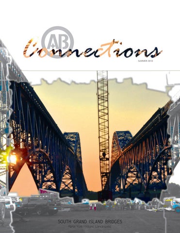
S0UTH GRAND ISLAND BRIDGES New York Historic Landmarks
Contents
SOFTBALL 3
Rekindling an old time softball tradition SAS TOWER 11 SOUTH GRAND ISLAND BRIDGES
The focal point of the NY landmark bridges project
The first section arrives TRAINING 14
AB field engineers travel to CA from across the US & abroad FROM THE CEO 16
Design / build should be the new standard AWARD OF EXCELLENCE 19
Based on innovative performance on Chesapeake Bay Bridge STORIES 20
From a lifetime with AB Much appreciation to the following individuals for their contribution to this issue: Matt Brownlee John Callaghan Butch Darr Chris Deklewa Mike Flowers Rob Hetzell Kara Mullin Carl Schwarz Scott Swamback Maudee Parkinson
HISTORICAL LST 21
In Pittsburgh, September CONNECTING THE BAY BRIDGE 22
26 splices between the OBG sections
26
AB PUBLISHED 31
The name American Bridge is 140 years old FLASHBACKS 33
An icon that posed unique challenges WELLNESS PROGRAM 11
newsletter
by Kadi Camardese Please contact the AB Communications & Marketing Department with news & inquiries: kcamardese@americanbridge.net
AB COMMUNITY 12 CORNHOLE LEAGUE 13 HUMAN RESOURCES UPDATES EARL DENNER RETIREMENT NEW HIRES & CURRENT CONTRACTS 34
11
n o i t i d a r T ll a b t f o S A
A
10
, circa 19
ll team B softba
Ba Notill field in ce th e car Gary, I s! ndian
a
This spring American Bridge rekindled an old time softball tradition. The first American Bridge team (that we know of) played in Gary, Indiana circa 1910. Then in the 1980’s, when the center of operations was located in downtown Pittsburgh, Pennsylvania there was a team for a few years that included some present day employees such as Dennis Martin, Lanny Frisco and Berry Bender. Dennis Martin is still participating on the current team which started in May 2010 and is based out of the company headquarters in Coraopolis, Pennsylvania. From the fifteen person roster the American Bridge players are:
Dennis Martin Joe Rynn Brent VanArsdale Ben Reeve Eric Lansbery Ashley Roberts Kadi Camardese SUMMER ’10 .
PAGE 3 AB Connections . PAG
South Grand Island Bridges PH0T0S: KADI CAMARDESE
AMERICAN BRIDGE REPLACES THE DECK 0N A NEW Y0RK LANDMARK MARKING THE F0CAL P0INT 0F A TW0 YEAR, $48M PR0JECT
Project Manager:
Rob Hetzell
Superintendents:
Angus Adams Larry Tussy
“
General Formen:
Clearly the events in these four critical months of the project represent a good example of the logistically and technically complex projects on which American Bridge thrives.
Joe Grabar Ira Jones
General Superintendant:
Ugo Del Costello
”
Project Engineer:
Matt Brownlee
Rob Hetzell,
AB project manager
Field Engineers:
Bill Batzel Brian Binder Chris Deklewa Drew Merritts Kara Mullin Zach Osei Joe Stilson Scott Swamback
Existing deck of the northbound South Grand Island Bridge waiting to be lifted by the red crawler crane using the graymetal rigging and blue teacups
SUMMER ’10 .
AB Connections . PAGE 4
scope
k r o w of
When entering Grand Island, New York from the south you will find spectacular twin steel 1047m (meter) bridges with deck truss Replacement of th approaches and steel thru-arch mainspans. The South Grand e deck and barrier systems for the north bound bridge, re Island Bridges serve as an artery throughout northern New York placement of all 168 be arings on both br and Canada carrying interstate 190 across the Niagara River beidges, repairs to all 52 of the concrete pier s an d removal of the tween the metropolitan regions of Tonawanda, Buffalo and northbound brid ge’s sidewalk Niagara. They are among the most stunning landmarks in upstate New York. The southbound bridge construction dates back to 1935. With a growing population in the area the northbound bridge was built in 1963 to look identical to the first one, maintaining the 1930’s e, circa 1935 Southbound bridg aesthetics. I September 2008, American Bridge received a contract from the In Th New York State Thruway Authority valued at approximately $48 million. Currently, with just two months remaining, American Bridge is completing the project’s focal point - replacement of the existing deck on the northbound bridge with prefabricated exodermic deck panels. Exodermic deck is a proprietary product for which the D.S. Brown Company is the patent-holder. Each deck panel is made of a reinforced concrete slab with an unfilled grid. The deck panel’s modular system enables rapid construction, as opposed to rehabilitating with cast in place reinforced concrete. The use of these panels, combined with quick setting concrete stitches or closure pours, allows the deck replacement to be performed at night. This avoids inconvenient public traffic delays. Moreover, this technology reduces the deck weight, enabling the bridge to achieve higher live load ratings and prolonging its lifespan. Approximately 100 American Bridge employees and subco contractors are working to improve and rehabilitate the So South Grand Island Bridges. Daytime crews are commisSuperintendant, Angus , sio sioned to prep for the overnight deck work as well as to Adams and field engineer Chris Deklewa re replace bearings on the north and southbound bridges. Fr From 9 p.m. to 6 a.m. during the 2010 construction se season, the night crew removes a portion of the deck aand positions a new deck panel, secures the section with a closure pour of rapid setting concrete and installs parap pet barrier and railing. These precast exodermic deck p panels are being placed concurrently on both the girder aand truss portions of the northbound South Grand IIsland Bridge. SUMMER ’10 .
General superintendant, Ugo Del Costello
AB Connections . PAGE 5
“
If there is any indication of high winds, lightning or thunderstorms, the work is not started because the overnight completion cannot be jeapordized. Matt Brownlee, lead project engineer
The project site during nightime is a fast paced atmosphere, since the process must be completed in its entirety in order for the bridge open on time for traffic the next morning. “If there is any indication of high winds, lightning or thunderstorms, the work is not started because the overnight completion cannot be jeapordized. On nights with these uncontrollable delays, the team takes advantage of the time by completing miscellaneous tasks and prep work,” according to Matt Brownlee, AB’s lead project engineer. The following outlines the detailed process which must be executed in only nine hours: View of ur and deto e r u s ic lo f c raf ) lane signs n of T of Traffic n io o t ti c c the traffic f te e o o t r ll P o a , d r 5 In 15 n posted. and P nance a re. By 8:4 n u te e s e in e lo c a b c n M e e ( v is tena . bridg ge ha e MPT bridge; th – Main 9:00 p.m und brid , starts th th r o e u e b e o th s th r in u e g fo o ing en r th ts m is load t to allow adjacen a orth ove h , AB field e n te n ig o th g n B ls A in h ti to d c S Joe traffic .m. ea cks, t of the les hea , the res , box tru d bridge at 7:45 p of vehic s ly n r s e e e u c u n tt o li n o u b e e g c u n th n seq ps, saw ual nor d the lo . Simulta g the us out pum til 6 a.m r will lea r in n e g r b u , u s r d m to e e e e il d rew m cks, tra maintain ms. an AB c ickup tru p n will be : r e g tt in eous ite a minutes d n p a lu ll ic c e ff c in a is tional tr typically other m by-direc ipment, ent and u q m e ip h u it q ge w ing e the brid s, survey m a r e o h rs, excavato n molitio e D g in s of the – Rail oth side b n o g ss to is waitin le to cro ic The crew h e v t s rch is r the la tion. A to li o m e bridge fo d rail then e traffic teel and s e begin th th h ug break cut thro ployed to m used to e is e m hoe ra ching th ta e D t. e a 1½ ton arap ble xisting p d to ena te le up the e p m o ust be c railings m eck. of the d removal truction the cons
yard
8:45 p.m.
9:00 p.m.
uts 9:20 p.m. in- Cg is typically performdeodf
ea Saw cutt e and ah r u s lo c arathe Railing demolition sequence t. In prep prior to n o fr k r o k c w e y d tl xisting the nigh ut the e o g in ft li er span tion for the gird in k c e d e limeter) panels, th mm (mil 0 5 9 2 m idth. cut either 9.1 is cut into s n o ti spans is 40mm w c s 4 e s s 2 u l r tr a o e in ck in th 130mm longitud el. . The de ither a 2 g e n g lo in ach pan v m e a .2 h in 2 n 1 d o r le ti o h sec ore dril sely, eac les are c o h g transver in ft r li ”diamete Four 2.5
SUMMER ’10 .
AB Connections . PAGE 6
9:40 p.m. – Remove Existing Deck
“
The challenge in installing these precast panels arises from the limited time frame we are allotted, and therefore the limited distance we can replace. Scott Swamback, field engineer
”
Rigging
The f gin our-pa g is rt ri fi g tea cup tted w ith lifte lifte d r Ma with t s and n wo cra itwoc wle 410 r cr On an 0 e pos crane es. it is to r ioned Shifting em o ove n lan dec d g k the sectio irder ns a oth e 70’ n x 80 r sits o d n bar ’ se a g c trus e to re tional s m old portio ove ns. dec T a fla k is se he t has bed tr t onto u t low he ab ck tha Lifting ility t er / t sec o t ilt s tio o th dum ns ca e n ped be .
11:00 p.m. – Clean Steel & Surveying
Now that the deck sections are removed, ironworkers use fingerscalers and air grinders to clean any rust and excess concrete from the newly exposed steel. As this is taking place, a field engineer lays out the shear studs on the floorbeams. Many contractors subcontract survey work, but American Bridge nearly always self performs this task in order to retain full control over geometry. Field engineers receive survey experience as part of their course and field preperation in AB’s five-year field engineer training program. Positioning the replacement deck sections for the South Grand Island Bridge is critical; exceeding the 6mm tolerance has the poWood planking for temporary access in order to clean tential to dramatically decrease the life & prepare the existing steel floor beams span of the bridge due to uneven wear The four reinforcing needle and tear. Misplacing a section early-on beams, previously installed for could result in failure of the bridge. temporary strengthening by American Bridge, are being American Bridge field engineer, Scott removed during the cleaning / Swamback, set up the overall survey procedure for the project, and also leads the nightly surveying I stage survey effort on the truss spans. “The challenge in installing these precast panels arises from the limited time frame we are allotted, and therefore the limited distance we can replace. In my opinion it’s harder to maintain a straight line with smaller deck segments . PAGE 7 than with larger ones,” says Scott. SUMMER ’10 . A AB Connections C
For the most accurate positioning, first the points and distances of the existing steel are obtained. As the new deck sections in the girder spans are placed, AB field engineers Kara Mullin and Chris Deklewa survey to ensure precise positioning. Leveling bolts are used to adjust the panel vertically, while heel bars are manipulated with come-alongs and port-a-powers for horizontal modifications. The survey steps for each deck panel replacement include: The floorbeam points are shot to confirm they match the stationing in the contract drawings. Survey equipment is positioned over a preset aluminum survey disk closest to the demo area. Taking a reverse azimuth reading, backsighting is used to establish the center line on the bridge as well as horizontal and vertical control. The centerline is marked on each floorbeam, from which the offset is measured in order to establish the edge of deck on east and west side.
To retain full control over geometry on critical jobs such as this, AB has incorporated surveying into it’s five-year field engineer training program. SUMMER ’10 .
AB Connections . PAGE 8
Studs are laid out on each floor beam, and the surrounding area is cleaned with a grinder to allow for proper weld of the shearstuds to the floor beams.
1 2
3
4
e
nc e u q e s ion t c e r e n
io
t c e s k c De
Lift
Place
Adjust Adjust
12:30 a.m. – Place New Deck
The new panels are lifted from below and set with the Manitowoc 4100 crawler crane and then a lifting beam attached at eight locations to minimize stress on panels. Eight leveling bolts are pre-adjusted from existing survey data to minimize the time expended to set the new panels. The exodermic deck sections are set atop 3/4” leveling bolts. In the deck girder spans, there are four leveling bolts across each panel at the break in the precast concrete over the girders – 16 bolts in 9.1m panels and 20 in the in 12.2m.
1:30 a.m. – Surveying II
Scott Swamback created an analytical surveying system to aid field engineers; an innovative idea that is a great advantage on a job with strict time schedules such as South Grand Island. He derived equations that replicate what was used to determine deck elevations in the contract drawings. These equations allow calculation of elevation and offset at any location. Three equations are used to work up the bridge at a constant slope, over the center arch and back down the bridge at a constant slope. Scott explains the program: “It was designed to replicate the data provided in the contract drawings, which provide elevations at respective stations and offsets. When entering any station and offset on the bridge, the program will output a theoretical elevation for that point. Meanwhile, shooting any point on a panel, the data collector coupled with a total station outputs that point’s station, elevation and offset. The station and offset are entered into the software program and
then compared with the elevation shot to determine if the panel needs to move up or down. This method is unique in that the panel can be shot at any point to determine where it needs to go rather than using the points provided in the contract.” According to Kara,“The two hour surveying process is the most demanding part of my shift because the deck sections are positioned with one minute tolerances of 2mm vertically and 6mm horizontally. Chris and I shoot the points and adjust the sections numerous times to obtain proper deck elevation for each panel.” For individual exodermic panels, the elevation must be recorded in a minimum of four corners and then compared to the data in Scott’s software program. Bolt adjustments are made as needed to come as close as possible to the moving forward elevations and the offset locations. Leveling of each panel is made incrementally until it is within 2mm of the theoretical elevations. SUMMER ’10 .
AB Connections . PAGE 9
2:30 a.m. – Concrete Pour
Next the crew installs ¾” plywood forms on the outside face of the deck and 20 gauge steel sheet and angles to form the haunches and closures between deck panels. Loose rebar is placed in the unfilled grid openings of the exodermic deck closure pours.
n t erectio segmen ours k c e d l p ure ccessfu for clos After su placed is te re conc
Approximately 7.5cy (cubic yards) of rapid setting concrete is used for 9.1m pours and about 9cy for a 12.2m pour. This concrete gains its required strength for traffic at 3,000 pounds per square inch within two hours of placement.
3:30 a.m. – Barrier Placement
Work for the night is more than halfway complete. Now it is time to set the precast barriers into place which are held down by bolts anchoring through the deck. The girder section uses 914mm rods and the truss section rods are 460mm long. The day crew has already attached the posts. The barrier segments are erected by the crawler crane. After the barriers are placed, they are adjusted to line and grade by the ironworkers.
4:30 a.m. – Railing Installation & Temporary Transitions The last two tasks of the evening (railing installation and temporary transition traffic plate erection) are completed with ample time to spare before the 6:00 a.m. opening of the bridge to traffic. Clearly the events in these four critical months of the project represent a good example of the logistically and technically complex projects on which American Bridge thrives. Deck replacement began in April and is right on schedule to be complete in September,”explains Rob Hetzell, project manager. Ongoing Work Bearing replacement In addition to the deck replacement, approximately 168 steel bearings are being replaced with new elastomeric bearings on the northbound and southbound bridges. To accomplish this work, AB crews are using a method of jacking developed by American Bridge Engineering’s Stanley Walker and Carl Schwarz, chief engineer and construction engineer respectively. “We wanted to develop a method of jacking that would provide the field operations as much flexibility as possible, allowing them to reuse the same falsework with minimum modifications at every bearing location. This proved to be the most economical approach,” says Carl. One 280 ton jack is used per column. The distance from the ground to the girders varies at every pier, so the challenge is to accommodate the dissimilar heights with a minimum amount of pieces. Instead of fabricating a custom piece for every location, AB made the falsework columns with utmost adjustability ranging from 11’ to 50’ in three inch increments. This flexible system accommodated every location except for the abutments. Past Work American Bridge has completed additional work in past seasons, including repairs to the 52 northbound and southbound concrete river piers, removal of the northbound bridge’s sidewalk, reinforcement of the truss sections with transverse steel needle beams to provide stability for the deck replacement and the bolting of parapet tubing to the existing floorbeams for new barrier anchorage at the edge of the bridge. SUMMER ’10 .
AB Connections . PAGE 10
The Tower has Arrived The SAS Project celebrated another milestone on Friday, July 9th with the arrival of the Zhen Hua 18 carrying the first lift of the iconic main tower. The four 1000mt shafts and associated framing were unloaded by Tuesday, July 13th and work is underway to facilitate installation. Senior members of the American Bridge / Fluor team joined the Toll Bridge Oversight Committee and Caltrans in hosting ZPMC’s President Kang Xue Zeng and a delegation of representatives from China for a ceremony recognizing the milestone. Tip up of the first shaft took place the week of July 19th. Stay tuned to details of the installation in future editions of AB Connections.
www Bay Bridge progress: http://www.googleearth.com
WELLNESS PR0GRAM
It is never too late to start participating in the wellness program. New and recently re-hired employees who have missed out on a few months’ initiatives can still participate at their own pace. If you would like to try the Drop 10 in 10 Program or the 10,000 Steps Challenge, just contact the HR (Human Resources Department) and we will send you the kit. It is important to mention that each month we will send out correspondence and focus on one or two of the items from your wellness points checklist. Please note that not all items on the wellness point’s checklist will be focused on – you must take the initiative to complete some of the goals yourself. Most of the items you can complete at your own pace any time throughout the year. As of June 30th, we have had 42 employees earn a $50 Visa gift card and five employees earn an extra vacation day to use in 2010. We would like to offer new incentives and programs for 2011 – all suggestions are welcome! Just send a quick email to Kathy Bonetti (kbonetti@americanbridge.net) with your ideas. Here is what you can look forward to over the next few months with the Wellness Program: August - Our focus will be on the CPR and First Aid certifications. These are life skills that you will not regret taking the time to learn – and it’s a great way to earn some wellness points. To find a class near you, simply
call 1-800-REDCROSS. Send HR a copy of your completion certificates and you will receive 15 points for CPR certification and 10 points for First Aid certification. Be sure to save your receipts for payment of the class because American Bridge will reimburse you for the cost of the training. September - We will be sending out communication regarding our September focus which is Bands on the Run; a 12 week program that will help improve your strength and flexibility. This program literally uses a giant rubber band that you can take and use anywhere at your convenience. American Bridge will cover the cost of the kit for you if you choose to participate with the start date of September 1st. More details to follow. October – During the autumn season we are all aware of the flu that tends to spread around easily. In an effort to keep people at work and not at home sick, American Bridge will reimburse you for the cost of getting the flu shot. When you get your flu shot remember to take a wellness goal completion certificate with you to have the administering professional sign and return it to HR. Please keep in mind that in certain situations the flu shot may be covered under your Highmark insurance so please take your card with you. Who will be the lucky individual to win the grand prize? Only five months to go! Good Luck to all who participate in the wellness program!
SUMMER ’10 .
AB Connections . PAGE 11
#/--5.)49
AS A RESP0NSIBLE C0RP0RATE CITIZEN, AMERICAN BRIDGE TAKES C0MMUNITY INV0LVEMENT SERI0USLY, DISPLAYING THEIR C0MMITMENT THR0UGH SUPP0RT 0F CHARITABLE AND CULTURAL INITIATIVES
Miles of Smiles
See description below
On Sunday, May 16th, 2010 thirty-seven American Bridge employees gathered at the North Park Boathouse in Allison Park, Pennsylvania, to participate in the MS (Multiple Sclerosis) Miles of Smiles Race, winning largest number of contributors for the second year in a row. That is a ten person increase from AB’s 27 participants in 2009.
The race consists of a mix and match sign up where participants may walk or run five miles or one mile around a three mile radius lake. The total amount raised the last three years was $53,000, $1300 of which AB donated the last two years. All proceeds benefit the National MS Society. The founder of the MS Miles of Smiles, Ellen Stewart, shares her reason for launching the first race three years ago: Denise is 38 years old, married with a 9 year old son and has lived with MS every day since being diagnosed 14 years ago. She has relapses about every 1012 months, which knock her down for a couple months each, and her body has rejected all the current drug therapies. Yet, Denise is hopeful for new experimental meds coming soon. She is also the kindest, most generous, most uplifting person that I know. Her will to live a long, happy life has inspired me to organize the first and now the third annual MS Miles of Smiles run/walk.� The 2011 race is scheduled for May 22nd at 9:00 am at North Park.
www Information and race results: http://www.msmilesofsmiles.com
Plants for Paws
American Bridge employees attended the second annual Plants for Paws perennial sale on Saturday, June 5th, at the Spring House in Eighty Four, Pennsylvania. Betty Robison, wife of American Bridge welder/fitter John Robison, founded the event in 2009 to help animals in need. Approximately 1500 plant species were for sale along with other gardening paraphernalia. The 2010 event was a great success, raising over $5000 in proceeds to benefit the Washington Area Humane Society.
www Information: http://www.plantsforpaws.com
Front row: fHunter Marshall, Bob Chance (AB), hCrocket Chance, nBrodi Camardese, Kadi Camardese (AB), Cindi Machi (AB), Bryce Machi, uBiscuit Machi, qKeesha Mykich, Denise Mykich Middle row: Saunie Kosar, Nik Marshall, Tricia Chance, Eric Lansbery (AB), Danielle Davison (AB), Jennifer Pelligrene (AB), Judy Sacco (AB), Karen Roman (AB), Michelle Dohmlo, Kelly Carney, Liam Carney, Carson Carney (AB), Eva Carney, Bryn Carney, Back row: Dave Kosar (AB), Steve Eichenlaub, John Murphy, Angela Felker, Bill Batzel (AB), Bill Felker (AB), Anthony Deramo (AB), Joe Rynn (AB), Dennis Martin (AB), Henry Mykich (AB), Trever Kennedy Not pictured: Laura Mann, Any Graff (AB), Kris Graff, Ryder Graff, Joe Machi
NEW AMERICAN BRIDGE C0RNH0LE LEAGUE “Bean bag toss” a.k.a. “cornhole” is a game that’s been catching on for years primarily at backyard barbecues, tailgating events and company picnics. Here at the AB headquarters in Coraopolis, we’ve created a lunchtime cornhole league. Interest in playing the game was first noticed at last year’s annual meeting at Nemacolin Woodlands Resort. Discussions of a league continued through winter and by spring we acquired 26 players for a total of 13 teams! League games are scheduled during lunch on Mondays and Tuesdays, leaving the rest of the week for make-ups and reschedules. League play will continue through August allowing each team to play each other one time. Following the league will be a single elimination series style tournament to be followed by the finals which will be held at the 2010 annual meeting at Nemacolin. The league has been great for inter-company camaraderie and team building, and of course, the database tracking statistics creates a little friendly competition. From left: Larry Smith, Matt Murphey, Andy Kalas, Barry Bender, Richey Now, if only Pefferman, Ralph Whitney, Laura Jamison, Andy Graff, Danielle Davison, Keith Bassano, Carl Schwarz, Brent VanArsdale, Brian Silvers, Dave Kosar, there was a Eric Lansbery, Kathy Bonetti, Kadi Camardese and Ashley Roberts place to play Not pictured: Karen Roman, Wayne Davis, Dan Edwards, Bill Batzel, indoors for a Janet Cordero, Jen Pelligrene, Henry Mykich, Brad Saver and Debbie winter league… Easton hmm…
RETIREMENT On May 7th, 2010 Earl Denner retired from his senior estimator position at American Bridge Manufacturing (ABM) after nearly 11 years with the company. Preceding his career at ABM, he worked as a manufacturing engineer and then as an estimator at Pittsburgh Des Moines Steel, Inc. Earl has been instrumental in the development of the ABM Company and the District, which was formed in 1999. The formation of ABM represented American Bridge’s re-entry to the steel fabrication business, which had played a central part in the company’s history from 1900 to 1984. After retirement Earl plans to travel and spend more time with his family.
HR UPDATES
Beneficiary Forms It is very important to keep your beneficiary information up to date. You can get a 401k beneficiary form or a life insurance beneficiary form from the American Bridge Access site under HR Forms or your project administrator can provide them to you. If you are unsure of your current beneficiaries, contact the HR department at 412631-1000. Annual Open Enrollment Annual open enrollment is the only time of the year you can make changes to your benefits without a qualifying event. A qualifying event is one of the following: • Marriage • Divorce • Birth/adoption/legal custody of a child • Employee gains/loses coverage under spouse’s plan • Child meets/loses dependent eligibility status • Change in work status of employee’s spouse or dependent • Entitlement to Medicare or Medicaid • Annual enrollment or new hire enrollment of employee’s spouse or dependent You can make a change to your benefits within 30 days of the qualifying event. Contact the Human Resources Department at 412-631-1000 as soon as you become aware of any changes.
Earl De nn his imm er (center, bac ediate fa k) and m his retire ment lu ily following n courtes y of AB cheon, M
SUMMER ’10 .
AB Connections . PAGE 13
Training PH0T0S: WAYNE DAVIS, AB TRAINING SPECIALIST
AMERICAN BRIDGE FIELD ENGINEERS BASED THR0UGH0UT THE UNITED STATES AND ABR0AD GATHERED AT THE SELF-ANCH0RED SUSPENSI0N SPAN SUPERSTRUCTURE (SAS) PR0JECT IN 0AKLAND, CALIF0RNIA T0 FURTHER THEIR 0N-THE-J0B SKILLS AND INDUSTRY KN0WLEDGE BY ATTENDING TRAINING SESSI0NS SIX AND SEVEN PRESENTED BY CIVIL ENGINEERING EXPERTS.
SUMMER ’10 .
AB Connections . PAGE B
Session
June 23 - 25
SUBJECT MATTER:
Structural concrete overview, form work and post tensioning – Neil Napolitano Pile driving, deep foundations and sheet piling – John Callaghan, P.E. Barge flotation – Kevin Smith, P.E. Boat trip, action planning and feedback – Wayne Davis ATTENDEES:
Brian Binder – Mayport Wharf Delta, Florida Will Campbell – Castaway Cay Enhancement, Bahamas Chad Ford – RFK Triborough Bridge, New York Mike Hartranft – Bronx-Whitestone Bridge, New York Kevin Lynch – Kentucky Lock Railway Bridges, Kentucky Drew Merritts – South Grand Island Bridge, New York Bruce Phillips – Throgs Neck Bridge, New York Zach Rosswog – Chesapeake Bay Bridge, Maryland
Session
June 21 - 22
Joe Rynn, James Dipasquale & Simon Laming
SUBJECT MATTER:
Tour of self-anchored suspension span job – Wayne Davis and SAS Personnel Crane charts, rigging design, shackles and cables – John Schober, P.E. Site work and excavation – Joe Hoepp Environmental issues and hazards in construction– Chartis Insurance Safety, OSHA and Cal (California) OSHA – Henry Mykich Action planning and feedback – Wayne Davis ATTENDEES:
Matt Brownlee – South Grand Island Bridges, New York Kelvin Chen – SAS, California James Dipasquale – KY Lock Railway Bridges, Kentucky Laura Furtado – Vehicular Bridge Repl., Rhode Island Levi Gatsos – SAS, California Sara Hansel – SAS, California Simon Laming – Special & International Projects, Scotland Andre Markarian – SAS, California Dan McNichol – SAS, California Adam Roebuck – SAS, California Adam Reeve – SAS, California Joe Rynn – Emsworth Dam Bridge, Pennsylvania Zach Vanlemmeren – Bronx Whitestone, New York Jon Weaver – Chincoteague Bridge, Virginia Katherine Quillin – SAS, California
Laura Furtado & Sara Hansel
SUMMER ’10 .
AB Connections . PAGE 15
from the ceo Design-Build – Delivering Bridges in less time at reduced cost
THE DESIGN-BUILD METH0D 0F DELIVERING BRIDGE PR0JECTS IS N0T NEW. H0WEVER, IN MANY PLACES IN THE USA IT IS STILL IN THE EXPERIMENTATI0N PHASE.
SUMMER ’10 .
AB Connections . PAGE B
Robert Luffy, president & CEO
This means that special decisions and procedures are required to use it, sometimes including time consuming state legislation. In most states, much discussion, planning, study, and debate accompanies any initiative to deliver a bridge project using the design-build methodology. Even though dozens of projects have been successfully delivered using this method, we are not yet realizing its full savings potential because except in a few places (Florida and Missouri are notable ones), it is not a mainstream delivery process. This means that the lack of protocols and accepted practice slows down the process. Moreover, the design-build projects that do happen often fail to take full advantage of the expansive saving potential of the process. This is born of the compromise that is usually required for a state to gain approval to experiment with design-build. I believe that it is time for the States and the Federal Government to make a concerted push to deliver bridges using the design-build method the standard rather than the exception. When this occurs we will be able to deliver bridge projects from concept to opening in significantly less time, and we will be able to build significantly more bridge deck for the same investment. And this will happen without any degradation in the quality of the finished product.
TIME SAVINGS
In most cases the bridge owner will retain the responsibility of stewarding the project through the NEPA (National Environmental Policy Act) process. Most major projects will require the preparation of an EIS (Environmental Impact Statement) and the obtaining of a ROD (Record of Decision) that supports the preferred alternative. This process is important and lengthy. Design-build is not advocated as having a role in shortening this process. From the point in the project delivery cycle where the ROD is obtained, however, design-build results in shorter project durations.
developing consensus on the best alternative, gaining approval to initiate design, assembling the team to manage the design, preparing the design and beginning construction. How long does this take? At least 18 months to 24 months. Now think about the same process within a schedule driven design-build environment. Now how long? Twelve months is routine. The average of nine months of time savings over a 57 month project (21 months design, 36 months construction) represents 15% of the schedule! This is one of the important reasons why design-build is an indispensible tool to accelerate overall delivery schedules.
Design-build accelerates project delivery by advancing the point in time when the contractor guaranteed schedule begins. The design, permitting and preparatory works that previously took place before the contractor-led design-build team came on board now takes place within their strongly schedule – incentivized watch. In its pure form, this means that bridgetype decisions must be made within tightly scheduled time durations. The private design-builder, with a keen eye on financial results, has enormous stake in ensuring that the schedule is met. The penalties in liquidated damages and extended overheads for not meeting, and conversely the cost savings and incentives for beating schedules create a highly schedule driven process. Think first about the traditional public sector DOT process of preparing bridge type design alternatives (using the EIS alternatives as the starting point),
Design-build also allows the overlap of design and construction activity, driving further time savings. Follow on actions to decisions made months or even years ago in the traditional design-bid-build process now happen as quickly as prudently possible. As a foundation solution is conceptualized and agreed in a process that was already influenced by market forces, field risk evaluations, equipment and manpower availability, and the innovative power of designers and builders working together, the design-build team begins assembling the resources and planning the field construction work. As the concept advances to final design in concert with the bridge superstructure design development, permits Orlando Airport Intermodal Transit guideway, Orlando, Florida are obtained and American Bridge design-build contract work is begun well in advance of when it could be in a traditional
SUMMER ’10 .
AB Connections . PAGE 17
approach. Superstructure long lead materials are procured, and shop drawing design commences while the final design checks are being undertaken. Also, the designer’s models are seamlessly transferred for use in the contractor’s erection engineering development, enabling the earlier assembly of resources and allowing time for optimization and better safety planning for the field construction activity. These huge time savings realize the productive capacity of the transportation improvements faster than under older methods, with multiplier benefits resulting from the more efficient movement of people and goods over our transportation systems. The time savings also reduce the period that the public is at risk from the deteriorated condition of our bridge infrastructure, including high maintenance costs, risk of collapse and exposure to earthquakes.
“
C0ST SAVINGS
Design-build saves cost because the design is optimized for construction. An integrated designbuild team is driven by competition to ensure that the design is in harmony with the most current market information, i.e. materials cost, labor cost and tradition, and supplier and subcontractor markets. The design-build team plans the design around the contractor’s preferred execution method, taking into account his particular equipment, sequencing plan and site conditions. The design is made to accommodate the erection method, avoiding the need for later alterations and their attendant submittals. The
design-build bidders can direct the design toward the scheme that minimizes the risk for their particular operational situation, so that risk premiums are minimized. The details of design, which often comprise the largest percentage of man-hours to construct, are optimized to be as straightforward as possible, and also such that the detail activities that are on the critical path are minimized. Owners and design engineers often manage a project with the objective of minimizing materials (like steel), but cost is often saved by buying more material with simplified details. Finally, as we have seen above, design-build results in a faster schedule, reducing everybody’s overhead. It’s not hard to see how the aggregate benefit of these efficiencies can exceed 15% of the cost of a bridge project!
I believe that it is time for the states and the Federal Government to make a concerted push to deliver bridges using the design-build method the standard rather than the exception.
SUMMER ’10 .
AB Connections . PAGE 18
”
www
GET INV0LVED!
ARTBA (American Road & Transportation Builders Association), through the BPPC (Bridge Policy and Promotion Council) is actively involved to ensure that funding the effort to reduce our nation’s deficient bridge inventory from the unacceptable current level of about 25% remains a top priority in the ongoing debate about the new Transportation Bill. The BPPC is also committed to maximizing the value of bridge infrastructure obtained for the investment dollars allocated, and to accelerating the overall delivery period for new, replacement, and rehabilitated bridges. We believe these goals are best achieved by facilitating discussion, understanding and refinement of project delivery methods used for bridge projects in the United States. The BPPC is also engaged in helping the Lions Gate Bridge, Vancouver, British Columbia, Canada states develop design-build contracting American Bridge design-build contract procedures. Our Project Delivery Committee, consisting of a cross section of industry participants, is in the process of developing a Code of Industry Practice. The purpose of this effort is to provide State DOT’s, bridge authorities, and other bridge owners a ready reference of the state of the industry practice – how best to address issues such as permitting, bidding documentation, aesthetics, utilities and other third party rights, design-build selection procedures and legal documents, proposal deliverables, insurances, stipends and so on. www Get involved in this process and make your opinions count by contacting Allison Wenograd at awenograd@artba.org.
AMERICAN BRIDGE WINS AWARD 0F EXCELLENCE
Baltimore, Maryland - American Bridge received an Award for Excellence in Concrete Construction by the Maryland Chapter of the ACI (American Concrete Institution) based on it’s excellent and innovative performance on the Chesapeake Bay Bridge Deck Replacement and Rehabilitation project.
includes the removal and replacement of 23,092 lineal feet of traffic railing, replacement of four expansion dams and installation of an aerodynamic stabilization winglet and fairing in the suspension bridge. American Bridge manufactured the precast units at its Chesapeake Bay concrete fabrication plant at Sparrows Point, Maryland.
This project involves the removal of 193,000 square feet of deck in the westbound suspension and through cantilevered truss spans; replacement with precast, post tensioned units during nighttime lane closures. The work also
The Chesapeake Bay Bridge Replacement and Rehabilitation job and the project team members were recognized at the Excellence in Concrete Awards Banquet held on May 27, 2010 at the Engineering Society of Baltimore, Maryland. SUMMER ’10 .
AB Connections . PAGE 19
JUST A FEW ST0RIES FR0M A LIFETIME CAREER WITH AMERICAN BRIDGE Butch Darr spent his entire 47-year career with American Bridge and our subcontractors there were about can Bridge. He began in 1959 as a truck driver in the 120 men working there, men whom he thought were Saxonburg mill; then in 1961 became an ironworker spending too much time on breaks, all because of that (under Red Haney, an infamous name some of you doggone wagon. It didn’t take long before he banned may have heard before) on the 62nd Street Bridge. In that wagon from coming on the job! It was just the way 1963, after graduating with a two year accounting dehe was. Nevertheless, the Superintendent made sure it gree from Point Park College, Pittsburgh, Pennsylvania, continued to stop by his office so he could get his mornButch was hired as a field clerk at the Ambridge, Penning coffee. sylvania, accounting department. There he served as a liaison between the office and the foremen on projects Not too long after this debacle, a dog moved in under across the United States. After six months he became the office trailer. It was an ugly dog, with missing teeth assistant and all. In timekeeper, its defense, then time it was a keeper loyal, caring for the dog that next ten understood J0E GRYGIEL, AB SUPERINTENDENT years until the dangers Joe worked for Butch at American Bridge 14 years. he was of a conpromoted struction to expediter, eventually working his way to materiel cosite. Yes, this dog felt its duty in life was to protect each ordinator in the Pittsburgh office. Finally, in 2006, Butch person on the job site. Anyone who walked by its camp retired as the manager of equipment at the Coraopolis without a hardhat on would get bit, every time. When headquarters plant. ‘Superintendent-coffee-wagon’s’ wife came to visit him at the project, she was no exception to the canine safety During these years, Butch worked on hundreds of jobs rule. Luckily the dog was headed to the humane society - so you can imagine the thousands of stories he has as due to pregnancy, because it sure didn’t have a chance to tell. AB Connections asked him to share a few of his at saving its home after that incident anyway. favorites: That was almost 40 years ago. Bob Luffy was a field I worked with Bob Luffy on the PNC Building and the engineer in those days. He was a very bright guy with Civic Arena in Pittsburgh, but the first time we worked lots of common sense and acted nothing like that distogether was on a the I-275 twin bridges that went gruntled Superintendent. He was able to communicate from Ohio to Kentucky. There were several fights and well with the workers on the job, even better than most union problems associated with this project. We had of the other young field engineers. a Superintendent at the time who stirred the pot a lot, you might say. I can remember there used to be food I remember one day Bob was working on the bridge wagons that would go around to the jobs offering with one of the best workers on the entire job. His sandwiches, rolls, coffee and etcetera. Between Ameriname was Jumbo Gurthrie. Jumbo was angry with
Butch truly lived by the golden rule: “He was loved by everyone - if he didn’t have anything good to say about you he wouldn’t say anything at all.”
SUMMER ’10 .
AB Connections . PAGE 20
‘Superintendent-coffee-wagon’ for banning further deliveries – actually he was infuriated! So he said to Bob and I, “for two cents I’d quit this job!” So Bob reached into his pocket and gave the guy two pennies and off he went. (We found him at a tavern at the lunch break and he was back to work the next day.) That was quite humorous and unexpected. There was a time when my coworkers were making bets on my life. A seven pound icicle dropped about 90’ from the I-275 twin bridges and broke its fall with the back of my head. This was another funny point on that job, not for me, but for some of the other guys. At this point AB Connections had to stop Butch and ask him how long he was out of work after the head injury. His response: “Ahh (pause), about a half-hour.” Oh! You recuperate very quickly. “Yeah, a couple people thought I was dead, then I just went back to work; that is how it was then.” Butch has been retired for three years. He and his wife remain in their Pittsburgh suburb home, with their children and grandchildren close by. About 20 years ago while reminiscing they estimated an average of 16 relocations in the first 10 years of marriage. You’ve seen many retiree names in recent issues of AB Connections because we feel a company is as good as its employees. We have heard from Jack Bryce, Bill Gibson, Leo Kupiec, Kenny Lewis, David Reese, Charlie Shipp and many others who know Butch Darr or have at least crossed paths with him. Their stories are intertwined and humorous, unbelievable and sometimes sad. However, these memories remain hidden unless they choose to share them with the rest of us.
HIST0RICAL WWII NAVAL SHIP VISITING PITTSBURGH Bob Luffy, American Bridge president and CEO, will serve as honorary chairman of the LST (Landing Ship Tank) 325 welcoming committee to kick off the ship’s arrival to Pittsburgh. The ship was built in Philadelphia in 1942; however, its design is identical to those built by American Bridge during the same era. A little history from AB Connections winter 2010 issue: LST’s were rugged and versatile vessels used in WWII for transporting general cargo, prisoners, casualties, locomotives, vehicles and any remaining items. Initially they were built in traditional coastal shipyards, but with increased demand the large scale fabricating facility in Ambridge was tapped to produce higher quantities at quicker rates. These ships were 328’ long and could transport loads in excess of 4,000 tons across the Atlantic and Pacific oceans. From 1942-1945, the Ambridge Plant of American Bridge produced 119 of the LST’s, an average of one every eight days or about four per month. Tours of LST 325 will be administered September second through the sixth from 9:00 a.m. to 5:00 p.m. daily Pittsburgh’s North Shore dock.
In future editions you will find features highlighting those who spent their lives contributing to the company, the men agree it is important to carry on American Bridge’s rich culture and storied history. Butch Darr leaves us with this: “The one thought that comes to mind when I think of AB, is the pride that we had, and still have, in the company - knowing that we could do any job, any place, any time. We are the best in the complex bridge building business and other companies looked up to us because we could do all of the jobs they couldn’t do.”
943
round 1
ta LST buil
SUMMER ’10 .
AB Connections . PAGE 21
connecting the bay bridge BY J0HN CALLAGHAN, AMERICAN BRIDGE AREA MANAGER
The SFOBB (San Francisco-Oakland Bay Bridge) is a complex, SAS (self anchored suspension) bridge project with a variety of difficult pieces of work. One of the more challenging items is making the 26 splices between the OBG (orthotropic box girder) sections. These sections are approximately 29m (meters) (95’) wide, 5m (16’) tall, from 2080m (70-266‘) long and weigh between 480 -1,450mt (metric tons) (530-1600 tons). These extremely large sections of bridge deck will be linked through a combination of bolted and welded connections to create twin 615m (2,000’) road decks (see the spring 2010 issue of AB Connections for full coverage of the bolted connections). The field welded OBG connections are the topic of this article; however, the tower welding may be a subject within AB Connections in the future. The OBG field welds are an integral part of the erection sequence. The erection of subsequent OBG and CB (cross beam) sections require an engineered minimum level of connectivity at each previous field splice. In addition to bolting, a welded deck plate and a bottom plate are typically the minimum requirement before additional OBG’s or CB’s are erected. Stated another way, the welding is squarely on the critical path because it is impossible to erect the next piece without the seismic connectivity that it provides. Dan Ieraci, American Bridge welding superintendent, runs the production field welding work for Jerry Kent, American Bridge general superintendent. All of the OBG field splice welds are “full pen”, also known as complete joint penetration welds, and are subject to 100% ultrasonic testing. Field welding tasks for the exterior skin of the box section for each OBG splice include: one deck plate, two edge plates, two side plates and one bottom plate, for a total of six joints. The edge plates on either side of an OBG are not necessarily the same thickness, nor do the side plates maintain uniformity from one side of the OBG to the other. Each weld joint is unique with different process and heat requirements. All the skin plate joints are butt joints with single V groove welds, with backing bars. The welding encompasses both manual and mechanized processes, including gas shielded FCAW-G (gas shielded flux cored arc welding), SAW (submerged arc welding), and SMAW (shielded metal arc welding). Backing bars are tacked and sealed with SMAW or FCAW-G and subsequent production welding is FCAW-G and SAW. Repairs are made with SMAW and FCAW-G.
NO TWO ALIKE Each weld joint is unique with different process and heat requirements. All skin plate joints are butt joints with single V groove welds with backing.
SUMMER ’10 .
AB Connections . PAGE B
fit up
‘FIT UP GEAR’ includes tools used to fit the joints, such as: brackets, tank pins, square nuts and worm plates
TANK PINS are also used with the worm plates to hold the backing bar
american welding society orthotropic box girder gas shielded flux cored arc welding submerged arc welding shielded metal arc welding non-destructive testing
AWS OBG FCAW-G SAW SMAW NDT
Precise joint fit-up is the foundation of successful welding. Even though these joints are fit-up in the fabricator’s yard as part of the OBG shop assembly, it is not uncommon to see misalignment at the joint when the OBG’s are delivered to the jobsite. When the OBG’s are slid together and the joint is initially closed, the deck plate backing bar is slipped in and supported on the U-rib connection plates. The deck plate and bottom plate are the first joints to be fit. A refinement of the traditional dog and wedge fit-up has been used on SFOBB. Drawing on its extensive welding experience base and culture for innovation, American Bridge superintendents and engineers developed and sourced specialized project specific ‘fit up’ aids that optimized the alignment process in a manner that ensured that the required tolerances would be met.
certified welding inspectors procedure qualification record weld access platform visual testing magnetic particle testing ultrasonic testing
SUMMER ’10 .
CWI PQR WAP VT MT UT
AB Connections . PAGE 23
deck plate The deck plate weld receives the most attention because it joins the traffic carrying surface plates of one OBG to the next. It is a single V groove, flat position weld with a permanent backing bar. The weld is 27m (90’) long, made with SAW and the joint must be fit and aligned in compliance with AWS D1.5 3.3.3. This means that the maximum allowable planar misalignment (or high-low) from one side of the joint to the other is 2 mm (millimeter), slightly thicker than a nickel (American five-cent piece). A tightly fitting backing bar is also very important for a successful weld. The limit on backing bar fit is 2mm per AWS D1.5 3.3.1.1 and 3.13.5. It is a full 27m (90’) long piece of half inch thick flat stock that is dropped in the hole as the deck section is slid home. After the deck section is pushed into position and the initial bolting begins, the deck plate is fit by installing the fit-up gear across the deck at approximately 2’- 0” on center in locations of planar misalignment. The two ends of the deck joint sometimes require a closer spacing. The backing bar is fit from below and held tight to the bottom of the joint with wedges on the U-rib connection plates, tank pins and worm plates. After the deck plate is fit, the welding shelters made from bottomless connexes are put into place, covering the length of the deck joint and protecting the work from weather and water. Next, the backing bar seal passes (full length tack welds, made with stick) are made. The entire length of the joint is carefully examined and the fit-up gear is removed so that the pre-heat system, subarc track and tractor equipment can be put into place.
SUMMER ’10 .
AB Connections . PAGE 24
The deck plate weld is an example of a mechanized process using a power source and subarc tractor. This self propelled tractor is programmed for travel speed, amps, volts and wire feed speed. The machine is operated with a pendant control. A pre-heat system is used to maintain the interpass temperature of 150 degrees with propane weed burners used for spot heat. The welding is slightly backstepped in order to minimize distortion. The flux is not recycled; two air powered vacuums and chippers and slag hammers are used to remove the used flux and pieces of slag from the finished passes. Starts and stops are ground before welding over them with the next pass. After the production welding is accomplished, preliminary VT (visual testing) is performed, under fill is checked and necessary stick fills are made. The backing bar stays in place under the deck. After grinding, the inspectors perform VT, MT (magnetic particle testing) and UT (ultrasonic testing) on the entire weld. Any rejectable discontinuities are marked accordingly and repaired by excavating with grinders and filling back in with stick or wire. These repairs are subject to additional VT, MT and UT inspections. If they are found to be acceptable, the joint is painted with a temporary primer. The typical repair rate on a length basis is on the order of two percent. Beneath the deck plate, toward the outside edges of the deck are stiffeners made of 485 MPa (70ksi) plate material which require manual welding with SMAW. A special procedure is required for this work – the butt joints are double bevel, double-Vgroove welds.
A STAND UP grinder is used to grind the deck weld
POSITION the induction heat system, subarc track and tractor equipment after the entire length of the joint is carefully examined and the fit-up gear is removed
One of the challenges with the side plate inside weld is the tight clearance between the equipment and the stiffeners
edge plate The edge plate is a vertical up weld joint that most closely resembles “normal� field welding. It is a butt joint with a single-V-groove weld done manually with FCAW-G. This weld is made against a backing bar, which is held in place with tank pins and worm plates. Determining whether to install the backing bar on the inside or outside of the joint depends on how the fabricator prepped the joint. From the outside, it is welded with the wire feeder from either a float or the WAP (weld access platform). From the inside, the weld is made sitting upon the stiffeners. The pre-heat and interpass temperature is maintained with the pre-heat system. The back gouge is made free hand with either a plasma cutter or a carbon arc both followed by grinding. The back weld is completed in the same manner with FCAW-G from the opposite side. Once the back weld is complete, the exterior skin of the OBG is ground smooth using electric grinders, and the VT, MT and UT are performed by QC. The NDT is performed from both the faces and sides of the joint, any necessary repairs are made, and the joint is painted with temporary primer.
side plate
ANCHOR the backing bar with fit up gear
HEAT BLANKETS insulation installed on the outside face covering the joint and fit-up-gear
FCAW-G weld made from the inside
The side plate is aligned like the deck plate with fit-up gear on the outside face of the OBG, however the fit-up-gear is also used to hold the backing bar in place. After the side plate joint is fit, the pre-heat system and insulation are installed on the outside face covering the joint and the fit-up-gear. The FCAW-G weld is made from the inside. One of the challenges with the side plate inside weld is the tight clearance between the equipment and the stiffeners. Special equipment and procedures were developed that enabled the machines to pass through the 50mm space between stiffeners (25mm from the center of the root gap to the end of each stiffener). Another challenge with the inside side plate weld is that while by code it is a vertical up weld it is more suited to a flat position procedure. A special procedure was qualified for this weld. Once the inside weld is complete, the induction heating and the fit-up gear are removed from the outside of the OBG and the backing bar is detached by back gouging. Next, the back gouge is cleaned with the grinders and the pre-heat is reinstalled. Then the FCAW-G back weld is placed overhead. After grinding, the NDT is performed from both faces and both sides of the joint, and any necessary repairs are made.
SUMMER ’10 .
AB Connections . PAGE 25
INSIDE WELD is made with SAW and Lincoln Cruiser
bottom plate The bottom plate fits like the side plate. The fit-up gear is on the outside face of the OBG with the backing bar held in place and the induction heat over it. Meanwhile inside the OBG the backing bar is sealed with two full length tack welds made with SMAW or FCAW-G. The inside weld is made with SAW. After the inside weld is placed, the pre-heating system, fit-up gear and backing bar are removed. The back gouge is made and the back weld is made overhead with FCAWG. Finally, the back weld is ground flush and the NDT is performed.
safety The safety requirements for SFOBB welding procedures are typical compared to similar welding operations, including a fire-watch when dropping fire over the historic building located under part of the SAS. Ironworkers wear welding hoods and soft hoods, jackets, gloves, fall protection, respirators and double eye protection while grinding. Forced air ventilation is provided with both 10hp (horsepower) supply and 20hp exhaust fans as well as associated hard ducting inside the OBG’s. Smaller fume handler fans and large box fans are also used.
quality control The ABFJV welding QC (quality control) effort is headed up by Jim Bowers of American Bridge. Jim is a welding professional, with experience as a fabricator, inspector and QC manager. He is responsible for maintaining adherence to the ABFJV Welding QC Plan. Jim is a positive contributor to the production welding process on the SFOBB SAS span. Daily inspection efforts are performed by Certified Welding Inspectors (CWI) and non-destructive
SUMMER ’10 .
AB Connections . PAGE 26
testing (NDT) technicians from Smith-Emery Inc., a sub-tier sub consultant to Leland-Saylor Associates. These inspectors perform the VT, MT and UT as well as the in-process inspection and surveillance, including machine setup and verification, pre-heat, post-heat and interpass temperature. The activities of the inspection personnel are distilled into essential weekly weld reports which Jim Bowers submits to the project owner (California Department of Transportation). These reports are the quality control record of the field welding; therefore they are very important to Caltrans. The inspectors are the last line of defense in our effort to deliver a quality product for the owner.
nondestructive testing
access & protection All of the OBG welds present access challenges. The deck plate weld is the most accessible as it is on the deck and in the flat position. However, because the deck is sloped and the subarc process does not work under water, the deck weld must be protected from the elements. Protection, especially against water intrusion, is provided by connexes with the floor removed that are mounted on the deck and sealed with silicone. The WAP’s (weld access platforms) provide access to the edge and side plates and were designed by Dan Hester, American Bridge field engineer, working with Levi Gatsos, American Bridge design engineer. The bottom plate is accessed from the typical truss crosswalk. Because of the rain and wind blown water, the use of various sealants became necessary to protect the work. Self stick flashings that work on wet surfaces and underwater were used to make diverters and drip edges above the work.
NDT (non destructive testing) must be performed on all OBG field welds. First a magnetic particle test reveals any root crack defects. Once the weld is complete, it undergoes visual testing to ensure that there is not any under fill, undercut, overlap or excessive reinforcement. Magnetic particle testing is performed next, which reveals any near surface discontinuities and surface cracks. Lastly the weld is checked from both sides of the joint and faces with ultrasonic testing. The OBG exterior skin plates are required to be ground smooth, so a UT scan in the transverse direction to the weld axis (referred to as a “D” scan pattern in the code), can be performed on the outside of the box girder. This scan pattern is used to find transverse indications in the weld, none of which have been found to this point.
BOTTOM PLATE is accessed from the typical truss crosswalk
SUMMER ’10 .
AB Connections . PAGE 27
repairs The ABFJV repair rate has been well under the acceptable welding standard of five percent. The welds done with the SAW process have a rejection rate of less than 0.5%. Any defects are usually found through UT indications and fall into three categories: lack of fusion in the root, slag inclusions or porosity. The lack of fusion in the root is caused by deficient penetration when positioning a seal weld or improper bead placement when making a pass. Slag inclusions are caused by insufficient cleaning or by rolling slag under a pass due to poor bead placement. In some cases the design of the joint and associated stiffener locations can increase the likelihood of rolling slag under a pass (the 50mm nominal space between stiffening elements inside the OBG comes to mind). Porosity is caused by lack of a tight backing bar fit up and gas delivery issues. A potential hazard in the absence of a tight backing bar fit up is for air and other contaminants to be sucked into the bottom of the joint where no shielding gas is present to protect the puddle. In other words, if the shielding gas delivery is interrupted by obstructions, then the puddle is unprotected resulting in porosity.
SUMMER ’10 ’10 . SUMMER
PAGE B28 AB Connections . PAGE
procedure qualification record PQR (Procedure Qualification Record) development was an important part of building a successful field welding program for SFOBB. PQR’s are required by spec and by code for the field welding on SFOBB. ABFJV developed the parameters for the various procedures by running test plates at the Ironworker Training Facility in Benicia, California. PQR’s were developed for each joint with more than one electrode type and manufacturer. This means that if in production a particular electrode did not have acceptable results; another could be substituted without waiting for the owner’s approval of a replacement PQR submittal. The owner has further restricted the procedure qualification by limiting the allowable variation in the welding parameters during the development of the process. The Contract Special Provisions state: “the travel speed, amperage, and voltage values shall in no case vary by more than plus or minus 10% for travel speed, plus or minus 10% for amperage and plus or minus 7% for voltage.” These value restrictions are not imposed as a D1.5 code requirement and are unique to this owner.
If the U-RIB is too close to the center of the root gap, then there is not enough “meat� of the prep sitting on the backing bar
lessons learned Good joint fit-up has proven to be a key to successful welding. Planar misalignment across the joint, backing bar gaps, and improper root gap are all symptoms of poor fit-up and are causes of defects and repairs. It has been discovered that spending ample time on the fit-up is less expensive than making later repairs. In addition, fit-up issues exceeding the contract allowances enable the owner to put a halt to welding and this is not acceptable under any circumstances. FCAW-G uses shielding gas. Reliably delivering shielding gas at the proper pressure and flow is critical to successful FCAW-G. AB experimented with a variety of fittings and has now developed procedures to ensure proper gas delivery. Gas shielded welding processes work because the shielding gas provides a controlled environment around the arc and puddle; this environment is clean and free from atmospheric contamination. If the shielding gas is blown away from the puddle there will be immediate problems, such as porosity. In order to field weld with a gas shielded process careful attention must be paid to providing protection for the shielding gas so that it is not blown away by the wind. As with gas delivery, AB has experimented to ultimately develop effective procedures to prevent against shield gas contamination. The hiring and retention of qualified ironworker welders is one of the keys to success on any job. ABFJV teamed with the Ironworkers Local 377, San Francisco, California, to provide test plates and testing for the welders at the hall. This collaboration has been successful in helping the job hire qualified welders. A large portion of the welding is performed with mechanized processes creating a formidable learning curve. Ironworker welders are often not familiar with subarc tractors normally used primarily in >> SUMMER ’10 .
AB Connections . PAGE 29
>>
shop applications. To the usual ironworker welder subarc is somewhat mysterious because there is no arc or puddle to look at, only a slight glow coming from under a pile of flux. ABFJV overcame this learning curve by providing additional training to the welders on specific equipment including plasma, Bug -O’s and subarc. Another fabrication issue involves the placement of the backing bar under the deck plate. The backing bar is held in place with wedges, fit-up-gear, worm plates and tank pins to fit inside the gap created by the ends of the U-ribs and the U-rib connection plates. If the U-rib is too close to the center of the root gap, then there is not enough “meat” of the prep sitting on the backing bar which can cause the root pass to blow through the backing bar. Prior review of the fabricator’s work is vital to confirm the weld prep and associated work has been properly executed.
OBG bolting and welding operations are required to be carefully coordinated. The initial bolting stipulation provides the minimum connectivity required to satisfy the seismic design criteria. As the OBG joint is bolted, the stiffness increases and the ability to further improve the joint fit-up is reduced. If the bolting gets too far ahead of the fitting, the joint cannot be fit to the contractual tolerances of 2mm or less of planar offset. However, in order to support and fit the backing bar under the deck plate, the bolting is essential. It is important to carefully monitor these operations so as to avoid problems between the welding gang and bolt-up gangs working on the splice. As the OBG’s are supplied with pre-applied finish paint, the team takes precautionary measures to safeguard them during the welding and gouging operations against damage from fire, sparks, slag, dross and other by-products. The use of fire retardant blankets, tarps and plywood has helped minimize the potential damages.
The success of American Bridge’s field welding efforts on the SFOBB relies on a combination of state of the art equipment, advanced procedures, skilled ironworker welders, dedicated supervision and QC. The low reject and repair rates are irrefutable testament to the success of ABFJV’s procedures and to the project overall. Looking to the future, surely obstacles will arise in the construction of the SFOBB’s east end, as well as the tower. However, American Bridge will continue to plan the work in advance taking careful consideration of its ever increasing experience, and will continue to experiment and innovate at the cutting edge of the industry. In this way our legacy for delivering ever higher quality complex bridges with competitive advantage will be sustained. The autumn 2010 AB Connections issue will give you a current behind the scenes view of the plant in China from the American Bridge perspective.
SUMMER ’10 .
AB Connections . PAGE 30
Flashbacks
The construction of the Unisphere icon posed unique challenges, as depicted by Superintendent Perry Whittaker:
Many phases of the job were so different from any work we had ever done that we sometimes wondered if we were doing the right thing. In the beginning of this project we found a need for new work expressions. Normally, we would use terms such as angles, beams, columns, girders, and trusses. These were useless at the Unisphere. Rather, we found ourselves speaking of parallels, meridians, hemispheres, longitudes, latitudes, degrees, north, south, east and west. That was just the beginning of our geography. We were to erect the land areas relative to their geographical locations. It wasn’t uncommon to hear a Bridgeman say. “I worked in Indonesia this morning and I’m going to New Zealand this afternoon”, or, “come over in South Africa and give me some help”, or, “go ten degrees north and 45 degrees west and make sure that ladder is secure.”
American Bridge designed, fabricated and constructed the Unisphere for the 1964 New York World’s Fair & Exhibition to celebrate the dawn of the space age. This iconic symbol is a 12 story, 500 ton representation of earth made entirely of stainless steel. The open frame is 120’ in diameter and supported by a three pronged support. The globe’s axis is 23.5 degrees from vertical, making it complex to understand in plan and elevation. The landmark has tubular pipe parallels, an”H” section equator and box section meridians. The land areas are built up rigidized metal sections. There are also three suspended orbits representing the nation’s then incipient space program, made of 8” stainless steel tubes.
50
UNISPHERE
Project type: Special structure Location: Flushing Meadows, New York Work commenced: February 15, 1963 Completion date: October 17, 1963 Duration: 244 days AB order no.: V-6160-62 SUMMER ’10 .
AB Connections . PAGE 31
American Bridge was responsible for the construction of this famous structure for the theme park’s millennium celebration. This unique work included the construction of a ‘2000 structure’ that cantilevers over Spaceship Earth, plus a variety of tent structures in the Future World Plaza. The structure is 260’ tall and consists of 450 tons of structural steel. There are seventy-four18” auger cast piles, a 4’ thick foundation mat slab, electrical lighting systems and architectural show set elements.
10
MILLENNIUM IC0N
This project involved the replacement of an existing single-leaf, Strauss type bascule bridge with a new vertical lift bridge for Peoria & Pekin Union Railway Company, with only a three-day shutdown to marine and rail traffic. The new bridge was built on the same alignment to make use of the existing approach spans. The new towers were built straddling the track at both ends of the existing bridge. The new lift span was assembled on a barge-mounted falsework bent. During the change-out, the existing bridge was removed and the new lift span was floated into position. The counterweight ropes were attached to each end and the new bridge was put into service. American Bridge field forces performed all of the erection and flotation engineering, steel erection, machinery installation and alignment and demolition work.
25
P&PU RAILWAY ILLIN0IS RIVER BRIDGE
American Bridge constructed a double cantilevered truss bridge approximately 3,588’ long with double track railroad on the lower deck and 44’ highway with two 2’6” sidewalks on the upper deck. There are seven falsework bents, two of which were made of bridge stringers and rested on mud sills. The other five bents were made up of truss members and bracing from the suspended span and set on the concrete foundations. Special shoes and jacking devises were made for use with all bents. Bent heights: one and four 45’, two 149’, three 280’, five 76’, six 121’ and seven 238’. Bents three and seven have ‘back legs’ so that the lower portions of the bents are braced. The total weight of steel in the seven bents is 1,997 tons. During the erection procedure the main steel of truss spans were erected by an S2 derrick traveler. A Jinniwink traveler erected highway deck behind the main traveler and the girder spans were erected by locomotive cranes. Two 60 ton and one 150 ton cranes were utilized on the job. Steel erection started from the south and proceeded to within one panel of the center of the suspended span. The equipment was moved to the north end of the bridge where the truss spans were erected and the truss was closed at the center. The girder spans at the ends of the bridge were the last spans erected in the operations from the two ends.
75
PIT RIVER BRIDGE
American Bridge constructed two truss bridges in New Brunswick, Canada consecutively: the St. Louis Bridge and the Tobique Narrows Bridge. The St. Louis Bridge was a pin connected through truss that had a span of 150’ with a 16’ center to center of trusses over the St. Louis River in Kent County. Its deck was made from 2” birch and spruce wood. Total weight of final structure was 74,695 pounds. The Tobique Narrows Bridge had two pin connected deck truss spans of 80’ and 200’ over the Tobique River. The structure’s final weight was 175,865 pounds.
100
Operations manager - Brian Peterson, project manager - Ernie Pinyot, superintendent, Ron Williams, field engineer - Bob Kick
Project type: Special structure Location: Lake Buena Vista, Florida Work commenced: January 1, 1999 Completion date: September 24, 1999 Duration: 266 days AB order no.: 482110
Project type: Bridge Location: Peoria, Illinois AB order no.: T-3001-15
Project manager - William Nichols, field engineer - John Schober, superintendent - Roger Larsen
Project type: Bridge Location: Shasta Lake, California Work commenced: December 27, 1940 Completion date: July 31, 1942 Duration: 581 days AB order no.’s: G7860S- G7865S; G7860N- G7865N
Field engineer - W.G. Bekerley, superintendent - E. Nimmergood
ST. L0UIS BRIDGE &
T0BIQUE NARR0WS BRIDGE
Project type: Bridge Location: New Brunswick, Canada Work commenced: January 1, 1902 Completion date: April 28, 1902 Duration: 117 days AB order no.’s: F1963 & F1964 SUMMER ’10 .
AB Connections . PAGE 32
AB PUBLISHED
THE AMERICAN BRIDGE C0MPANY NAME DATES BACK 140 YEARS
American Bridge Company was first incorporated in Chicago, Illinois in 1870 by Lucius Boomer. Boomer was an experienced bridgebuilder, having been responsible for the construction of many of the bridges for the Transcontinental Railroad from Omaha, Nebraska, to San Francisco, California, that took place in the 1860’s. After a series of reorganizations in the latter part of the 19th century, Boomer’s original American Bridge was the namesake and one of the 28 companies that were merged in 1900 to create the American Bridge Company that exists today. The acclaimed historian Stephen Ambrose details Boomer’s activities in his book Nothing Like it in the World:
The Men Who Built the Transcontinental Railroad. In April of 1867 there were 10,000 men working to build the Union Pacific Railroad (UP) through the Rocky Mountains. “In addition, L.B. Boomer, owner of the Chicago Howe Truss Bridge Company [and, in 1870, founder of the original American Bridge Company], with well over 1,000 working for him, was supplying the UP with prefabricated sections for bridges. These were made up of 12” x 12” x 16’ lumber, sent out from Chicago.” 1 As the UP was being built across Wyoming the Western Railroad Gazette reported, “The first corps of workmen have arrived for building the great Union Pacific Railroad Bridge. The contractor was L.B.
ng ken duri Photo ta on cti constru
d
l Railroa
tinenta
nscon the Tra
Boomer of Chicago who had built so many of the UP’s bridges and was generally thought to be one of the best (if not the best) in the country at his job.”1 The book American Bridge Building Companies 1840-1900 covers some of the early history of Boomer and American Bridge during the 1870’s: “This Chicago company was one of the largest of its period, comparable in size to the Keystone Bridge Company (Andrew Carnegie’s venture that was also one of the original 28 firms included in the 1900 merger that created today’s American Bridge) and Clarke, Reeves and Company, both of which started about the same time. Its contracts ranged from Texas, through the Midwest, to New England, where a two-level railroad and highway bridge was built at Fall River, Massachusetts. In addition to the usual structures the company built the Point Bridge at Pittsburgh, an 800’ suspension bridge supported by truss eyebars, and part of the Ninth Avenue Elevated Bridge in New York City.” 2
1 Ambrose, Stephen E. Nothing Like it in the World: The Men Who Built
the Transcontinental Railroad. New York: Ambrose-Tubbs, Inc., 2000.
2 Print Darnell, Victor C. Directory of American Bridge Building Companies
1840-1900. Washington, D.C.: Victor C. Darnell, 1984. Print.
SUMMER ’10 .
AB Connections . PAGE 33
PRSRT STD US POSTAGE PAID CORAOPOLIS, PA PERMIT NO. 7
Headquarters Office, Pittsburgh, Pennsylvania Michelle Dohmlo - Payroll Administrator Richey Pefferman - Accounting Supervisor Chincoteague Office, Virginia Michael McLoughlin – Superintendent Navy Pier 31, Groton, Connecticut Suzanne Rathbun – Project Administrator
CURRENT C0NTRACTS
MANUFACTURING
Huey P. Long Bridge Widening Fabrication, New Orleans, LA East River Park Bridge, New York, NY Unicorn Bridges, New York, NY Larimar Bridge Fabrication, Westmoreland, PA Clymer Truss and Bridge, Indiana, PA Bronx River Greenway Replacement, Bronx, NY Motor Parkway Bridge, Islip, NY Broadway Bridge, Portland, OR WESTERN
ABFJV Oakland Bay Bridge, Oakland, CA NEW Y0RK
NEW HIRES
1000 American Bridge Way Coraopolis, PA 15108 United States of America
TAMPA
Mayport Wharf Delta, Mayport, FL Castaway Cay Enhancements, Abaco, Bahamas Tampa Port Authority Phase 2B, Tampa, FL Estelle Pump Station Work Platform, New Orleans, LA Waskey Bridges, New Orleans, LA Arawak Port Development, Nassau, Bahamas PITTSBURGH
Kentucky Lakes Bridges, Grand Rivers, KY Emsworth Back Channel Dam Repairs, Emsworth, PA RICHM0ND
Chesapeake Bay Bridge Redecking, Annapolis, MD Throgs Neck Bridge Structural Retrofits, New York, NY Chincoteague Bridge, Chincoteague, VA Bronx Whitestone Bridge Structural Retrofits, New York, NY Pier R3 Repairs, Yorktown, VA RFK (Triborough) Structural Improvements, New York, NY Pier 31, Groton, CT South Grand Island Bridges Rehabilitation, Niagara River, NY Walt Whitman Deck Replacement, Philadelphia, PA Ogdensburg-Prescott Bridge Main Span Rehabilitation, Ogdensburg, NY
INTL SURFACE AIR LIFT US POSTAGE PAID CORAOPOLIS, PA PERMIT NO. 7
Headquarters Office, Pittsburgh, Pennsylvania Michelle Dohmlo - Payroll Administrator Richey Pefferman - Accounting Supervisor Chincoteague Office, Virginia Michael McLoughlin – Superintendent Navy Pier 31, Groton, Connecticut Suzanne Rathbun – Project Administrator
CURRENT C0NTRACTS
MANUFACTURING
Huey P. Long Bridge Widening Fabrication, New Orleans, LA East River Park Bridge, New York, NY Unicorn Bridges, New York, NY Larimar Bridge Fabrication, Westmoreland, PA Clymer Truss and Bridge, Indiana, PA Bronx River Greenway Replacement, Bronx, NY Motor Parkway Bridge, Islip, NY Broadway Bridge, Portland, OR WESTERN
ABFJV Oakland Bay Bridge, Oakland, CA NEW Y0RK
NEW HIRES
1000 American Bridge Way Coraopolis, PA 15108 United States of America
TAMPA
Mayport Wharf Delta, Mayport, FL Castaway Cay Enhancements, Abaco, Bahamas Tampa Port Authority Phase 2B, Tampa, FL Estelle Pump Station Work Platform, New Orleans, LA Waskey Bridges, New Orleans, LA Arawak Port Development, Nassau, Bahamas PITTSBURGH
Kentucky Lakes Bridges, Grand Rivers, KY Emsworth Back Channel Dam Repairs, Emsworth, PA RICHM0ND
Chesapeake Bay Bridge Redecking, Annapolis, MD Throgs Neck Bridge Structural Retrofits, New York, NY Chincoteague Bridge, Chincoteague, VA Bronx Whitestone Bridge Structural Retrofits, New York, NY Pier R3 Repairs, Yorktown, VA RFK (Triborough) Structural Improvements, New York, NY Pier 31, Groton, CT South Grand Island Bridges Rehabilitation, Niagara River, NY Walt Whitman Deck Replacement, Philadelphia, PA Ogdensburg-Prescott Bridge Main Span Rehabilitation, Ogdensburg, NY