Connections SPRING
SAS 78,199,729 feet of wire
78,831
ton tensile strength
1 7, 3 9 9 wires
137
strands 127 wires per strand
5.4
mm wire diameter
MAIN FEATURE: FL0RIDA PEDESTRIAN BRIDGES, PAGE 10
1
CABLE
2012
Connections
012 NG 2 SPRI
Connections SPRING
78,199,729 feet of wire
78,831
ton tensile strength
1 7, 3 9 9 wires
137
strands 127 wires per strand
5.4
mm wire diameter
1
10
Florida Pedestrian Design/Build Bridges
2012
SAS
MAIN
FEATURE
CONTENTS
CABLE
FEATURE: FL0RIDA PEDESTRIAN BRIDGES, PAGE 10
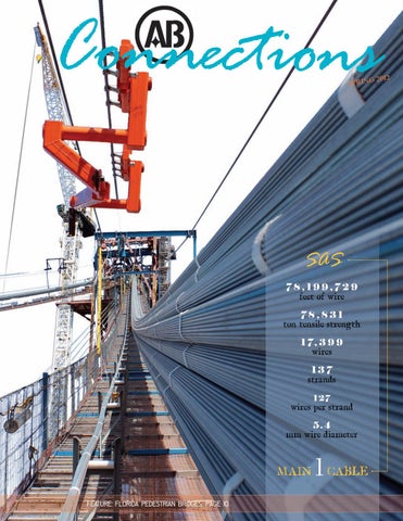
C O V E R The ABFJV loaded the fi rst of the 137 prefabricated parallel wire strands from the storage warehouse to a barge where they were brought to the project site and loaded onto swifts at the east end of the bridge deck. Here the strands will start their journey to form the main cable for the SAS.
thank you Much appreciat ion to t he following individuals for t heir cont ribut ion to t his issue: Mike Cegelis Kathy Diez Allen Dronko Bill Felker Phil Gerace Steve Jackson Kevin Moynihan Kevin Smith Paul Vitucci
Awards and current contracts SAS Human Resources/Wellness Tampa District Pier 31 Ribbon Cutting Bulkhead at NOAA Marine Operations Center Kentucky Lakes Bridges Sunshine Skyway Training AB Published Flashbacks Forth Replacement Crossing LVHR Update p
3 4 9 15 16 17 18 19 20 22 23 25 26
Chincoteague Bridge Grand Award for Engineering Excellence The main cable on this signature project has many firsts What to expect in coming months 2012 targets already exceeded U.S. Navy pier opens $6.3M design / build marine project completes Seven-year roadway and rail bridge project completes AB’ B s sixth anniversary stamp Field engineer graduates / supervisor training Commemoration of the Verrazano-Narrows Bridge, 1964 Historic bridges built by AB in Washington and Oregon Update on the new £790M ($1.3B) B cable stay bridge, Scotland World’s largest observation wheel
Robison Acres Plant Sanctuar y offers specialty perennia ls, select annuals and a variety of vegetables including numerous types of heirloom tomatoes that cannot be found at large corporate garden centers. To patronize this local venue take a drive to 476 Daniels Run Road, Scenery Hill, Pennsylvania any Saturday or Sunday from Apri l 28 through June 24 from 8:00 a.m. to 6:00 p.m. www.robisonacres.com 724-554-7338
To receive AB Connections electronically or view archived issues visit: http://www.americanbridge.net/Media/newsletters.php
Ne w Hi r e s
b K by Kadi adi d Camar Camardese mar arddese
Please contact the Communications and Marketing Department with news and inquiries: kcamardese@americanbridge.net
2
AB Connect Connections, ctions ns, Sp Spri Spring ring ng 22012 0112
Jeremiah Beiter, field engineer, Las Vegas High Roller, NV Peter Ferguson, quality assurance manager, off site steelworks, Forth Replacement Crossing, Scotland Shawn Hoffman, accounts payable specialist, Headquarters, Coraopolis, PA Joshua Ishibashi, senior quality assurance engineer, Forth Replacement Crossing, China Richard Lamb, design coordinator, Forth Replacement Crossing, Scotland Matt McCabe, field engineer, Coosa River Bridge, Clanton, AL Mark Patterson, works manager, marine operations, Forth Replacement Crossing, Scotland Daniel Raynor, design manager, Forth Replacement Crossing, Scotland Zachary VanLemmeren (rehire), field engineer, George Washington Bridge, New York City Sean Wichman, senior engineer, Forth Replacement Crossing, Scotland www.americanbridge.net
Award s
2008
Current
NEW Y0RK
As general contractor for the Chincoteague Bridge Project, American Bridge shared in the Grand Award for Engineering Excellence granted to the VDOT (Virginia Department of Transportation) by ASCE (American Council of Engineering Companies) this February. AB’s scope included the construction of a 59-span, 4,764’, environmentally sensitive replacement bridge for Virginia Route 175 connecting the mainland to Chincoteague Island. The two-lane, 43’-4” wide bridge utilizes typical 80’ precast concrete girder spans placed on top of cast-in-place concrete cylinder piles and cast-in-place caps located just under the roadway. The bridge length includes 4,035’ of mainline and 729’ of a secondary connector bridge providing access to Marsh Island. The navigational channel span is a 92’ single leaf trunnion bascule containing two 123’, 6” steel bascule girders 10’-7” deep. The weight of the structural steel in the bascule span is 417,460 pounds.
Walt Whitman Deck Replacement, Philadelphia, PA George Washington Bridge Rehabilitation, New York City
Current Contract s
Of the five Workforce Development Grants awarded by the AWS Foundation, one was given to a group of five companies which included American Bridge Manufacturing. When Pittsburgh Public Schools blocked funding for the 2011 summer welding program, the companies together provided the training space, left-over materials, equipment and even full-time jobs to the ten students when the five-week course completed.
MANUFACTURING
Walt Whitman Bridge, Philadelphia, PA PJ McArdle Viaduct, Pittsburgh, PA Clearfi eld County Plate Girder Bridge, Kylertown, PA PITTSBURGH Shore Parkway, Queens, NY Charleroi-Monessen Bridge Replacement, Charleroi, PA Cochran Mills Bridge, Armstrong County, PA Columbus Road Lift Bridge, Cleveland, OH Sun Valley Bridge Widening, Los Angeles, CA SPECIAL AND INTERNATI0NAL PR0JECTS 4th Avenue Bridge, Johnstown, PA Forth Replacement Crossing, Scotland, United Kingdom Wilson Creek Bridge, Marshall, AK Las Vegas High Roller Observation Wheel, NV George Washington Bridge Deck Replacement, New York, NY Dickey Prairie Road Bridge, Clackamas County, OR RICHM0ND I-80 Bridges, Clarion County, PA Pier R3 Repairs, Yorktown, VA Route 65 Bridge Rehabilitation, Pittsburgh, PA Bulkhead at NOAA Marine Operations Center, Norfolk, VA Montour Trail Bridges, Washington County, PA Wrightsville Beach Bridge, Wrightsville, NC Trinity County Bridges, Trinity County, CA TAMPA OPT Cofferdams, Reedsport, OR Platt Street Bridge Major Repairs, Tampa, FL Flamingo Loading Docks, Las Vegas, NV Red Bug Lake Road Pedestrian Overpass, Oviedo, FL Mansfield Bridge Rehabilitation, Allegheny County, PA Container Yard Shoreline Protection Works, Freeport, Bahamas Ambridge/Aliquippa Bridge Rehabilitation, Beaver County, PA Austal Navy Outfit Yard, Mobile, AL Blacklegs Creek Bridge, Indiana County, PA Courtney Campbell Causeway Design/Build Pedestrian Bridge, Tampa, FL Columbus Road Lift Bridge, Cleveland, OH Tom’s Harbor Channel Bridge Repair, Duck Key, FL East Pine Street Bridge, Snyder County, PA Golden Beach Bridge Replacement, Golden Beach, FL Cherry Tree Bridge, Indiana County, PA Berth 12 Wharf Extension and Container Terminal, Palmetto, FL SAS Barrier Transition, Oakland, CA Edward A Silk Memorial Bridge, Cambria County, PA WESTERN Runk Bridge, Huntingdon, PA ABFJV San Francisco/Oakland Bay Bridge, CA East Clinton Street Bridge, Ithaca, NY KANSAS CITY CE Plastics Tank Bases, Georgetown, PA Hurricane Deck Bridge, Camdenton, MO Rensselaer Street Bridge, Rensselaer Falls, NY Fuller Road Bridge, Albany, NY www.americanbridge.net
AB Connections, Spring 2012
3
SAS Main cable installation by ABFJV Technical Director Kevin Smith
Project Team Project Director Brian Petersen Operations Manager Bob Kick Technical Director Kevin Smith General Superintendent Jerry Kent Tramway Design Consultant Arne Roen Superintendents Danny Dunn Dave Meche Scott Smith Assistant Project Managers, Cables Adam Roebuck Scott Yeager Senior Field Engineer Katherine Quillin Field Engineers Eric Blue Levi Gatsos Ben Jones Zach Lauria Andre Markarian Adam Reeve Ankur Singh, Fluor
T
4
The main cable on this signature project has many firsts. Unlike a traditional suspension bridge where the main cables terminate in concrete anchorages, the cables on the SAS anchor within the bridge deck itself. There is one three-dimensional main cable on this suspension bridge; it loops around the west end of the bridge, drapes over the single tower and anchors at the east end of the bridge.
AB Connections, Spring 2012
www.americanbridge.net
The two activities that are exclusive to this bridge are hauling the PWS around the west loop, which is currently in progress, and the load transfer, which lifts the bridge off of the temporary truss and supports it from the cable, which will occur in late 2012.
PWS swift at east end
www.americanbridge.net
Two tramway systems have been designed to haul the 39-ton strand around this unique structure. The primary tramway system hauls the strand in the east-west direction through the north and south main span and side span. The primary tramway system is a single 36mm diameter haul rope that stretches in a continuous loop around the bridge. The primary haul rope is supported by tramway batteries on the catwalk and at the saddles and is driven by a 75 horsepower inhaul-outhaul traction winch. Attached to the primary haul rope are two haul frames, one on the north side of the bridge and one on the south, which will connect to the PWS socket. A secondary haul system has been installed at the west end of the bridge to pull the strand around the west loop on a trolley rail. The secondary haul system has a 14mm diameter haul rope driven by a 25 horsepower winch.
AB Connections, Spring 2012
5
PWS hauling north main span
H a ul i n g
6
AB Connections, Spring 2012
Hauling of a strand starts by connecting the PWS socket to the north haul frame. Once connected the primary tramway system pulls the PWS strand across the first leg of the bridge; up the north main span to the top of the tower and down the north side span, then north to the west deviation saddle. As the strand is hauled, it is placed in rollers on the catwalk and saddles to protect the galvanized coating on the wires. At the west end, the 500 pound PWS socket is transferred from the north haul frame to the secondary haul system trolley using a hydraulically actuated ‘transfer arm’. With the socket removed from the hauling frame, the primary haul system is operated in reverse to return the south hauling frame to the west end. The second leg of the trip is performed using the secondary haul system trolley, which pulls the PWS strand around west deviation saddles and jacking saddle in the west loop, placing the strand in rollers as it is hauled. When the socket arrives at the south deviation saddle it is again moved from the trolley to the south hauling frame on the primary tramway system using a transfer arm. The primary tramway system then completes the last leg of the trip by hauling the PWS strand up the south side span to the tower and down the south main span to the east anchorage.
www.americanbridge.net
Construction of a main suspension cable with overhead saddles or with a 180 degree horizontal bend has never been done before. On this project, we have both at the west loop, which required unique solutions in the design of the restraint system.
Restraint System
www.americanbridge.net
Strand forming
After hauling, the strand is floated out of the rollers using hydraulic ‘floating arms’ at the north and south sides of the west end and floating winches at the tower and east end. Strand floating and installation of the strand into the saddles progresses from the west loop, to the tower, and finishes at the east saddle and anchorage. To install the strand into the saddles, the strand must be transformed from a hexagon shape into a square shape. The strand in the west loop has been pre-curved and pre-shaped by the manufacturer but must be re-shaped in the field by ABFJV ironworkers after hauling. At the tower and east saddles, ABFJV ironworkers form the square from the hexagon shape. Construction of a main suspension cable with overhead saddles or with a 180 degree horizontal bend has never been done before. On this project, both occur at the west loop, which required unique solutions in the design of the Restraint System. The Restraint System is a series of 24 hydraulically powered holdbacks installed around the west loop that control the movement of the strand and use the existing tension in the strand to lift itself up into the west deviation saddles and jacking saddle overhead. The floated strand in the side span is held using a combination of the floating winches at the tower with the floating arm and restraint system at the west loop. As the restraint system holdbacks are incrementally released, starting at the jacking saddle and working simultaneously around both the north and south deviation saddles, the strand is lifted into the saddle trough and secured with timber blocking. After all of the restraints have been released, the strand is fully installed in the saddles at the west loop.
AB Connections, Spring 2012
7
Installation of the strand into the tower saddle has its own unique challenges due to the horizontal curve that results from the three-dimensional profile of the cable. Cable Design Engineer, Levi Gatsos states “Given the complexity of cable installation around the west loop, a significant effort was made to educate and train crews before the first strand was hauled using a temporary partial length strand. With the experience of this mock-up, the ironworkers, superintendents, and engineers have made the very difficult task to install the permanent strand almost look easy.� After installation of the strand into the saddles at the west end, the floated strand is then shaped and installed into the Tower Saddle. Installation of the strand into the Tower Saddle has its own unique challenges due to the horizontal curve that results from the three-dimensional profi le of the cable. The individual parallel wires want to take the shortest path through the Tower Saddle and gravitate toward the inside radius of the saddle. ABFJV has developed methods to control the movement of wires and hold them in place with timber blocking, screw jacks and clamps. Once installed into the tower saddle, the final step is to connect the strand to the east anchorages and shape and install the strand into the east saddles. After a strand is installed into the saddles, its position is measured and adjusted. When the temperature of the strands has normalized, the sag of the strand is measured relative to the reference strand (strand no. 1). Between saddles, the designed rotation of the main cable and counter-rotation of the strands requires a specific measurement for each strand. The strand sag is measured at mid-span using a set of large calipers. Adjustments are made by jacking the strand through the saddles to achieve the correct sag in each span. After a three week learning curve when only six strands were installed, the ten weeks since mid-January, 2012 saw another 107 strands installed and adjusted. As of the end of March 113 of the 137 strands were complete, and the final were finished by April 5. Work is now progressing on the remaining cable tasks: compacting, cable band placement, suspender rope erection and load transfer.
8
AB Connections, Spring 2012
www.americanbridge.net
“As the winner of the 2011 Wellness Program Grand Prize, I decided on a Western Caribbean cruise with my sister, Liza. We departed from Port Canaveral, Florida and our fi rst port-of-call was Cozumel, Mexico. AB constructed the cruise pier! Our next port-of-call was Belize, then Roatan where AB also constructed the pier. Our last stop was Costa Maya, but my favorites were Roatan and Mahogany Beach. Throughout the cruise, the water was incredibly beautiful, full of color and so inviting - I’m ready to go back.”
humanresources Vision The HR Department receives many calls regarding the Ameritas vision coverage. Two plans are offered through Ameritas: VisionPerfect and ViewPointe. ViewPointe is more of a traditional vision plan where there are allowances for each item. VisionPerfect has an allowance of $300 per year and that covers almost everything (exams, lenses, frames, contacts, etc.) up to the $300 allowance. One item that is not covered and comes up a lot is tinting. If you call Ameritas to check on coverage and you are enrolled in the VisionPerfect plan, they may not recognize you as having coverage. This is due to the fact that you can go to any vision provider, but you will be asked to pay up front and fi le a claim. Ameritas will only recognize you once a claim has been fi led. If you forget which plan you are enrolled in, have questions about the coverages, or have questions about completing the claim form, please feel free to call the HR Department at 412-631-1000. Change in Benefit Status An employee cannot make changes to their benefit status (i.e. adding dependent, removing a dependent, etc.) throughout the year unless there is a qualifying event. The only time you can make a change without a qualifying event is once a year during open enrollment. A qualifying event is one of the following: • Marriage • Divorce • Birth/adoption/legal custody of a child • Employee gains/losses coverage under spouse’s plan • Child meets/looses dependent eligibility status • Change in work status of employee’s spouse or dependent • Entitlement to Medicare or Medicaid • Annual enrollment or new hire enrollment of employee’s spouse or dependent You can make a change to your benefits within 30 days of the qualifying event. Contact the HR Department at 412-631-1000 if you need to make a change throughout the year due to a qualifying event. www.americanbridge.net
Highmark As of January 2012, Highmark has a new tool offered to all participants called MyCare Navigator. This is a health navigation and advocacy service offered to Highmark Members 24/7 to help resolve a variety of heath care and coverage related issues. Services offered are as follows: • Assistance in locating providers • Schedule doctor’s appointments, including assistance for expediting difficult appointments • Provide assistance in gaining second opinions if necessary • Find a network pharmacy • Identify a pharmacy that can administer specialty prescriptions • Find help that may be available to obtain non-covered prescriptions Members can access the service through the existing Blues On Call number at 1-888-Blue-428. There will be an option to choose MyCare Navigator.
wellnessprogram Coming Months This year’s program is moving forward successfully. Participation is high. Please keep in mind that employees can participate in most of the items at any time throughout the year unless otherwise noted. Here is what you can look forward to over the next couple of months with the Wellness Program: MAY – We will turn our focus to getting outdoors. The Human Resources (HR) Department will send out information as to where you can find local walk/ run-a-thons at or close to your location. If you choose to walk, run, or volunteer at an event, you will receive wellness points. JUNE – If you choose to join a gym, American Bridge will reimburse you for your initiation fee, up to $100. If you are already a member of a gym, you can get reimbursed for one month’s membership fee, up to $100. You will need to send the HR Department a copy of the paid bill in order to receive reimbursement and wellness points. JULY – The incentive this month is Biometric Screenings. These screenings measure your blood pressure, total cholesterol, LDL, HDL, Glucose and triglycerides. You can then take your test results and discuss them with your doctor at your next visit. Biometric Screenings are a good tool to early detection/ prevention. You will have the option to go to a LabCorp location near you or order a home test kit to administer the test yourself. Once the test has been taken, LabCorp will notify the HR Department as to who completed the test and wellness points will be awarded accordingly. Please keep in mind that no one but you will receive the actual test results.
AB Connections, Spring 2012
9
DESIGN/BUILD AB’s history with the Cross Seminole Trail and design/build pedestrian bridges in central Florida
Sanford Oviedo Orlando Tampa Clearwater
By the summer of 2013 American Bridge will have successfully completed six pedestrian bridge projects in Florida, four of which were design/build. Several are located on the Cross Seminole Trail in Seminole County Florida. The trail stretches from Sanford to Winter Springs connecting numerous residential communities. The Red Bug Lake Road Pedestrian Overpass completes at the end of May and work on the State Route 60 Courtney Campbell Causeway Multi-Use Trail will begin in the autumn of 2012. Since the Cross Seminal Trail opened in 2002, many pedestrian bridges have been built over major state roads and highways connecting the surrounding Seminole County area neighborhoods. The local hikers, runners and equestrians enjoy the trail for outdoor recreation and some locals opt for biking as a means for getting to work or to pick up their groceries. When AB completed the E.E. Williamson Road Pedestrian Bridge in the summer of 2005 it extended the trail further north to Sanford. The Cady Way Trail became the community of Winter Park’s connection to the trail in 2006. In the spring of 2008 the Cross Seminole Trail Bridge over U.S. 17-92 extended the trail southeast to Winter Springs. The completion of the Red Bug Lake Road Pedestrian Overpass in May will connect the missing link on the eastern side of the trail.
1. E.E. Williamson Road Pedestrian Bridge, Sanford 2. Cady Way Trail - Phase II, Orlando 3. Cross Seminole Trail Bridge over U.S. 17-92, Sanford 4. Clearwater Beach Pedestrian Bridge, Clearwater 5. Red Bug Lake Road Pedestrian Overpass, Oveido 6. Courtney Campbell Causeway Trail, Tampa
10
AB Connections, Spring 2012
www.americanbridge.net
1. E.E. Williamson Road Pedestrian Bridge Start construction: January 2005 Completion: July 2005 Final contract amount: $891,098 Service type: general contracting Owner: Seminole County AB team: Project Manager Matt Persing, Foremen Michael Rambus, Superintendent Kenneth Wooten, Carpenter Forman Darrell Brown, Crane Operator Michael Goff
This contract entailed the construction of a four-span, 285’ by 9’ pedestrian bridge over Interstate 4 north of Orlando, Florida. The work included the demolition of barriers and sidewalks on the existing E. E. Williamson Road Bridge, MOT (maintenance of traffic) on the existing bridge, construction of two concrete piers and two abutments, erection of eight steel girders, placing and finishing the concrete deck and installation of a new railing.
2. Cady Way Trail - Phase II This project included a 3,720’ extension of the Cady Way Trail in East Orange County, Florida. The work included a new 13-span, 685’ bicycle and pedestrian bridge, featuring a 245’ basket handle, tied arch main span over State Highway 436. The arch structure’s tie girder is a longitudinally and transversally post-tensioned, cast-in-place deck that has been constructed on falsework spanning the busy highway. The steel basket-handle pipe chord arch was erected after the deck was constructed, and the deck load was transferred to the arch via suspender cables. The arch rise is 38’; the arch thrust is resisted by the longitudinal post tensioning cables in the deck. The work also included 12 traditionally cast-in-place spans (10 at 36’ and two at 40’) resting on pressed-pile foundations, and an additional 3,035’ of at-grade trail.
Start construction: September 2005 Completion: November 2006 Final contract amount: $5,879,965 Service type: general contracting Owner: Orange County Parks and Recreation Division AB team: Project Mangers Allen Dronko and Matt Persing, Project Engineer Scott Tudor, Superintendent Kenneth Wooten, Equipment Operator Michael Goff, Foremen Michael Rambus, Surveyor Jere Bush, Project Administrator Dicky Stegall, Carpenter Forman Darrell Brown
3. Cross Seminole Trail Bridge over U.S. 17-92 This design/build project was won by American Bridge and its design subcontractor Ayres & Associates on a best value basis. The work included construction of 1,204’ of pedestrian/ bicycle trail including a 15-span, 698’ bridge that features a 208’, 135 ton serpentine shaped steel through truss main span over U.S. Highway 17-92 in Seminole County, Florida. The truss was assembled in the median of the highway and lifted in one pick during a nighttime closure. The bridge has architectural portals and a paint scheme to blend with the tropical environment. The foundations are spread footers except for the main span, which was pipe pile supported. The elevated approaches span 489’8” and were constructed in 14 architecturally finished cast-inplace spans. There was also 506’ of MSE confined embankment approaches, which also included cast-in-place concrete trail surface. The project included 8,700SF of MSE walls, aluminum pedestrian/bicycle railing running the length of the project, class-V and antigraffiti coatings, and landscaping throughout the site. www.americanbridge.net
Start construction: January 2007 Completion: April 2008 Final contract amount: $5,018,760 Service type: design/build Owner: Seminole County AB team: Project Manger Allen Dronko, Quality Control Manager Paul Vitucci, Superintendents Ugo del Costello and Marc Wooten, Carpenter Forman Darrell Brown The Best of the Best Award, ENR Magazine, 2008 Judges Award for Design and Best Engineering, Best Overall Project, Southeast Construction Magazine (McGraw Hill, division of ENR), 2008 AB Connections, Spring 2012
11
4. Clearwater Beach Pedestrian Bridge This $2.5M general contracting project included the construction of a pile supported concrete pedestrian bridge 320’ long, 16’ wide in Clearwater, Florida. Also within the scope was associated upland site work, including modifications to an existing parking lot; and two each, three-pile cluster dolphins for a neighboring dinner cruise vessel slip.
Start construction: October 2007 Completion: August 2008 Final contract amount: $2,419,347 Service type: design/build Owner: City of Clearwater AB team: Senior Project Manager Ronald Henderson, Project Engineer Andrew Spangler, Senior Estimator Bob Wind, Foremen Dewey McGhee and Craig Shellenberg and Superintendents Samuel Gass and Joseph Swett
5. Red Bug Lake Road Pedestrian Overpass This bridge project is the third constructed by American Bridge in recent years under a design/build contract in Florida and the longest simple-span pedestrian bridge in Florida, 170’ on pre-stressed concrete beams. It is part of the trail network in Seminole County, located at the intersection of SR 426 and Red Bug Lake Road. It has a total length of 735’ with a 170’ mainspan. All foundations are spread footings. The approach spans are cast-in-place concrete and the mainspan superstructure is composed of pre-cast/pre-stressed concrete beams with a cast-in-place concrete deck. The main span contains architectural enhancements including brick skinned columns, custom aluminum rails and precast cladding. Work also includes retaining walls and milling and resurfacing Red Bug Lake Road in the vicinity of the bridge and construction of 1,200’ of paved pedestrian/bicycle trail. Since the start of the project in mid-March of 2011, the bulk of the time was spent on building the piers and approaches which were completed in sequence. Project Manager Allen Dronko explains the process “We had a crew constructing the footings, another the columns and then another constructing the pier caps.” Next falsework was erected for completing the 15 cast-in-place concrete approach spans. Depending on the location, three
South cantilever wall footer being placed
South cantilever wall footer complete
South cantilever wall complete
Start construction: September 2011 Completion: May 2012 Final contract amount: $3,377,768 Service type: design/build Owner: Seminole County AB team: Project Manager Allen Dronko, Quality Control Manager Paul Vitucci, Superintendent Samuel Gass, Project Administrator Melissa Soranno, Surveyor Frank Benevides, Foremen Jerry Cabe, Darrell Brown and Glenn Lamb or four spans were placed at a time in a single continuous concrete pour. Once the decks were placed, the falsework was stripped and re-erected for the next section of approach spans. The most challenging part of the project was getting the 200,000 pound beams delivered to the site and positioned for the cranes to lift them in place. Quality Control Manager Paul Vitucci, “Without AB’s innovative thinking in anticipation of limited access at this stage of the project, there would have been further costs and significant delays involved. Our plan avoided any havoc and made the beam delivery a success.” The north side of the site has limited access and a narrow right of way. The south side of the site is a large open area providing the best access, however underground box culverts were located exactly where the beams would need to be staged. Due to the weight of the beams and delivery trucks and the fact that no reliable information could be obtained on the strength of the box culverts, staging on the south side
South columns
12
AB Connections, Spring 2012
www.americanbridge.net
Gopher tortoise: a protected species As with all projects, AB hired environmental consultants to survey the entire site before starting work to seek all possibilities of any wildlife nesting sites. About a dozen gopher-tortoise dens were found, and in accordance with Florida environmental practice the six active dens were relocated to near-by farms.
was also not an option. Without a south staging area available, with limited access to the north and the fact that the beams were permitted for hauling during daytime hours only, the project team developed a plan to close a lane that existed on westbound Red Bug Lake Road for staging the beams. The project team chose a two crane pick as the best and most economical solution for erecting the beams. A 250 and 275 ton hydraulic truck crane were selected for the task. The next problem was positioning a 170’ long beam in a small area. The bridge is perpendicular to Red Bug Lake Road so the beams had to be turned 90-degrees in order to position them for the cranes. To accomplish this, a temporary access road was constructed on the north side of the site that would support the weight of the trucks and the beams. Once a detour was set up on Red Bug Lake Road, the haul trucks could move the beams from the westbound lanes onto the east bound lanes and travel towards the bridge. As they approached the bridge the trucks took a wide turn and crossed over the median of the road and entered the north side of the site and traveled down the access road. This allowed the trucks to position the beams almost perpendicular to Red Bug Lake Road. The trucks had steerable bogies under the back of the beams and this allowed them to now back the beams into their final position for the pick. On the day the erection of the beams was planned, they left the fabricators yard in Tampa at 9:00 a.m., arrived in Oviedo around 1:00 p.m. where they were staged in the closed lane until the road could be shut down. In order to erect the beams, Red Bug Lake Road was completely shut down and traffic detoured around the site on surrounding roadways. The contract permitted
Concrete placement at pier cap six
North piers
Installing pier seven beam form work
continued on page 14
www.americanbridge.net
AB Connections, Spring 2012
13
DESIGN/BUILD - continued from page 13 AB a nine hour road closure window from 9:00 p.m. until 6:00 a.m. When Project Manager Allen Dronko was asked if there were negative feelings about the closure from the public he said, “No, in fact we had quite an audience.” Everything went as planned that night, both beams were erected, temporarily braced and the detour removed by 5:00 a.m. This aspect of the project went very smoothly because of preplanning by the project staff. One of the biggest time-savers was pre-installing as many pieces of the temporary beam bracing as possible on the piers and on the beams prior to lifting them into position. The team also developed a plan to install temporary guide blocks on the on the piers. This blocking guided the beams into their correct location the first time, eliminating extra time for measuring and repositioning during the pick. The team anticipated heavy traffic congestion once the detour Setting precast beams at span seven was set up, which would make it difficult to access the work area. Therefore the cranes arrived onsite earlier in the day and were staged in an adjacent parking lot with access to Red Bug Lake Temporary mainspan work platform and decorative brick installation at Road at the worksite. The crane company also installed most of the pier seven counterweights on the cranes while in the staging area, reducing the set up time required once they were positioned onsite. From that time until the end of May when the project completes, the team installed the intricate architectural enhancements on the Falsework and curb placement at spans five and six mainspan and approaches.
Pier eight entry to the mainspan nearing completion
Mainspan precast beams in place
South approach awaiting fence fabric installation South side with handrails and landscaping in place
Installing stay-in-place forms on mainspan precast beams
6. New project: Design/Build – SR 60 (Courtney Campbell Causeway) Multi-Use Trail The Courtney Campbell Causeway, Hillsborough County, will be Project Manager Allen Dronko’s third Florida pedestrian structure with American Bridge. This is the latest and largest pedestrian bridge project awarded to AB. This bestvalue, design/build project consists of a 3,200LF, 29-span, pedestrian bridge supported on pre-cast piling and utilizing pre-cast/pre-stressed concrete beams. The bridge will cross Old Tampa Bay adjacent to the existing SR-60 vehicular bridge. The project also includes 1,400LF of sheet pile wall and reconstruction of 3.2 miles of a paved multi-use vehicular and pedestrian trail leading up to the new bridge.
14
AB Connections, Spring 2012
Start construction: April 2012 Completion: July 2013 Final contract amount: $14.632.000 Service type: design/build Owner: Florida Department of Transportation AB team: Operations Manager Jack Chenneville, Project Manager Allen Dronko, Project Engineers Christopher Bergquist and Steve Norton, Quality Control Manager Paul Vitucci, Superintendent Samuel Gass, Administrative Assistant Joshua Robertson and Surveyor Frank Benevides
www.americanbridge.net
TAMPA DISTRICT Targets of 2012 With four contracts awarded in March and April, the American Bridge Tampa District has already exceeded its 2012 targets. The Florida projects include the Courtney Campbell Trail Design/Build State Route 60 in Tampa (see page 14), Tom’s Harbour Channel Bridge Replacement in Duck Key, Golden Beach Bridge Replacements in the town of Golden Beach and the Port Manatee Berth 12 Wharf Extension and Container Terminal in Palmetto. Mark Bell is Vice President of the district; he states, “We are excited to start the new projects, each of which has their own set of complexities. For example, the only access to Duck Key is Tom’s Harbor Channel Bridge, which is required to remain open at all times during the rebuild. The bridge deck will be removed and replaced while maintaining traffic utilizing one lane with 24 hour traffic control. The Golden Beach site requires rebuilding two 100’ bridges from barges while maintaining traffic as well. The plan is very similar to the Tom’s Harbor Channel Bridge, shifting traffic and utilizing one lane with traffic control. In addition to maintaining traffic the project is located within a residential area with zero land-based lay down area for stored materials. All of the materials required to build the bridge must be delivered and stored on the barge deck during construction of the new bridges. I am fully confident in my staff’s marine exposure and logistics experience – 2012 should prove to be a great year.”
We are excited to start the new projects, each of which has their own set of complexities. Mark Bell Tampa District Vice President
The Tom’s Harbour Channel Bridge Replacement project involves the fabrication and erection of a new concrete deck, sidewalk and traffic railing for the bridge. The scope includes demolition and removal of the existing bridge superstructure. Additionally, extensive repairs to the substructure will be performed. The bridge is 250’ long, 35’ wide and consists of five spans. Contract value: $1, 829,137; construction has already started and completion is expected before the end of 2012. The Golden Beach Bridge Replacements project involves the complete removal and replacement of two bridges and associated abutments. The scope also includes installment of a new sewer, ornamental lighting, soil improvements at the abutments, sub-base, paving and landscaping at the approaches. The bridges both span 100’ founded on 42” drilled shafts, cast-in-place pile caps, www.americanbridge.net
precast deck panels, cast-in-place decks and steel sheet pile abutments. Contract value: $7,207,431; start of construction will be June 2012 and completion is anticipated in August of 2013. The Port Manatee Berth 12 Wharf Extension and Container Terminal project involves an extension at end of the existing Berth 12 (previously built by AB) with a new 590’ long deep water steel combination-wall bulkhead with associated concrete cap, moorings and fenders. The waterfront work also includes dredging, rip-rap shore protection. On the land side the scope includes development of 10 acres of paved container storage area, including drainage structures, high mast lighting, water and force mains as well as fencing and other ancillary improvements. Contract value: $13,750,487; construction start date is May 2012 and work is scheduled to complete in July of 2013. AB Connections, Spring 2012
15
RIBBON CUTTING AB completes what is now the widest and most useful naval pier Groton, CT A ribbon cutting ceremony was held on April 12, 2012 to commemorate the completion of U.S. Navy Pier 31 in Groton, Connecticut. AB’s work on this $36M pier project began mid-summer 2009 and included the demolition of the existing pier and the construction of a new submarine pier 67’ by 550’. AB attendees included Operations Manager Ken Farrelly, Project Manager Kevin Moynihan, Project Administrator Suzanne Rathbun, Quality Control Manager John Boore and Concrete Superintendent Kenny Wooten. Officials such as Connecticut Governor Dannel P. Malloy, U.S. Navy Captain Completed Pier 31 South side of pier Mark Denno, Naval Construction Manager Robert Howland and Naval Engineering Tech Leo Tancreti were also present. AB’s relationship with the U.S. Navy began in 1919, and has since remained strong with the building of structures all over the United States including: cranes, radio and communication towers, shipfitter and boilermaker shops, crane runways, electric shops, piers and bridges. From Left to right: Lieutenant Commander Tres Meek, U.S. Representative Joe Courtney, U.S. Senator Richard Blumenthal, Captain and Commanding Officer of Naval Submarine Base New London Marc Denno, Connecticut Governor Dannel Malloy, Rear Admiral Richard Breckenridge, Commander of Submarine Group Two, Connecticut Lieutenant Governor Nancy Wyman, AB Operations Manager Ken Farrelly and Lieutenant Commander Michael Goolsby
16
AB Connections, Spring 2012
www.americanbridge.net
BULKHEAD $6.3M design/build marine project completes NOAA Marine Operations Center AB’s Richmond District recently completed Waterfront Bulkhead Repairs for National Oceanographic and Atmospheric Administration’s (NOAA) Marine Operations Center in Norfolk, Virginia. This $6.3M design/build project was awarded to American Bridge as best-value, based on innovative engineering that minimized the quantity of soil anchors and the company’s plan to move the utilities farther inshore to avoid conflicts underground. The existing 50-year-old steel sheet pile wall was rusted through in several locations along the 800’ long bulkhead. The new seawall is 3’ outboard of the old one, providing the owner, U.S. Army Engineer Norfolk District, with additional real estate. The scope included the installation of 180 pairs of 60’ long AZ37-700 epoxy coated steel sheet piles utilizing a vibratory hammer and placing a reinforced concrete cap. The cap was installed with integral sleeves to accommodate the subsequent drilling and installation of 105’ long soil anchor tie-backs at a 45 degree angle. Also included was the installation of underground sewer and electric duct banks, shore power stations, new coax and fiber optic cable, plastic timber fenders, composite dolphin pile clusters and a newly paved parking lot. The project was funded by the ARRA (American Recovery and Reinvestment Act). With a long history working for governmental agencies, AB overcame the challenges in procurement of materials and was successful in handling the additional associated requirements and certifications. There were multiple unique conditions to this project. One example is the underwater excavation to install a grout sleeve at the intersection of the new bulkhead with the old to seal each end. AB Superintendent Keith Hall designed a “Randall Straw” from a steel pipe pile, fabricated by AB welders. The straw-like instrument was driven into the river bottom and the air in the upper chamber was suctioned out creating a vacuum. As the ‘straw’ is withdrawn so is the excess material. The project team was exposed to new RMS (Resident Management System) software that will serve as an organizational aid in future contracts. The web based system centralized everything from submittals, daily reports and RFI’s to correspondence and billing. AB immediately embraced the new system, and as a result significantly improved overall performance on the project. The AB team was praised by the owner’s managers for setting a model standard for teamwork, efficiency and coordination. continued on page 21
www.americanbridge.net
AB Connections, Spring 2012
17
MAJOR PROJECT COMPLETION Kentucky Lock Highway 62/641 and P&L Railway Bridges
American Bridge was prime superstructure contractor for two new bridges, one roadway and one rail, to facilitate the widening of the navigation lock at Kentucky Dam for the U.S. Army Corps of Engineers. The two-lane roadway bridge is a 10-span, 3,116’ steel plate girder structure with a main span of 505’; with girders 14’ deep at the haunches. The single track railroad bridge is an 18-span, 3,095’
deck plate girder structure with a main through truss span of 500’. The project also included a weekend change out of a 120’ throughgirder railroad span (including foundations) over a state roadway, rehabilitation of the roadway and rail corridors across the dam, construction of a concrete access bridge to the powerhouse and construction of two precast/cast-in-place fishing piers.
List of AB employees who contributed to the project from 2005 to 2012:
“We have been at the Kentucky Dam site since 2005 and the successful completion of this challenging project is a testament to the hard work and dedication of the AB project team, of our subcontractors and suppliers and of our partnership with the Army Corps of Engineers.” Operations Manager William Felker
Operations Manager William Felker Project Manager Peter Balwant Field Engineers: Kevin Lynch, Joseph Rynn, James Dipasquale, Matthew Brownlee, Benjamin Reeve, Troy Bodenschatz and Taryn Skalski General Superintendents: Thomas Melvin, Mike Wade, and Jerry Kent Safety Manager Stephen Rogers Quality Control Manager Joseph Tumas Concrete Superintendent Scott Brother Operations Managers: William Felker and Brendan Lynam Corporate Engineering: Carl Schwarz, Win Patchell and Dan Edwards Superintendent Gary McDonald Ironworker General Foreman Larry Tussey Ironworker Foreman Kenneth Edelblute Safety Specialist Edward Wiseman Senior Vice President Lanny Frisco
Far right image: this 2,200 ton truss carrying the rail crossing mainspan was assembled on a single falsework bent in a specially prepared nearby yard. It was erected by floating two 195’ by 70’ barge assemblies with falsework towers and jacking platforms pre-erected. The truss was floated off its center falsework bent and to the erection point, and lowered onto its permanent bearings. The float-in was completed in an eight hour channel closure.
18
AB Connections, Spring 2012
www.americanbridge.net
SUNSHINE SKYWAY BRIDGE STAMP Post Office issues commemorative stamp - the sixth AB project to appear in a U.S. Postal Service commemorative issue As a partner in the joint venture general contractor that completed the iconic Sunshine Skyway cable-stayed bridge over Tampa Bay in 1987, American Bridge participated in the unveiling of the new Sunshine Skyway Bridge Priority Mail stamp. The unveiling, held on the shores of Tampa Bay with the bridge in the background on February 28, 2012, was attended by about 100 people, including AB’s Mark Bell. Speakers included former Governor of Florida Charlie Crist, several Postal Service executives and local politicians, and AB’s Michael Cegelis. In his address Cegelis pointed out that the bridge, completed less than seven years afterr the 2nd Sunshine Skyway was collapsed by a direct hit by the freighter Summit Venture, showed wed what can be accomplished with strong political and technical leadership and competent delivery partners. He praised the project team, including FDOT, Figg & Muller Engineers, s, the construction engineer SKYCEI led by Parsons Brinckerhoff, and AB’s partners Paschen n Construction and Morrison Knudsen Company. This extraordinary response was a call too action emanating from a physical disaster, and Cegelis asserted that we face a similar, if less ss concrete, disaster today. He gave two data points: one, gasoline taxes have fallen from 18 percent in 1997 to less than five percent today, and two, America’s infrastructure ranking byy the World Economic Forum has fallen from 8th in 2007 to 20th today. Only one country has fallen more in this short four-year period. He strongly urged for a new highway authorization act, and an increase in the gasoline tax, as the solution to the infrastructure woes of the country. Cegelis concluded by laying out a vision that there would be a commemorative stamp issued some 25 years from now celebrating a decisive action by this era’s leadership to renew American infrastructure.
1987
Sunshine Skyway Bridge (Cable Stayed) AB Order No.: W-2001 In joint venture with Paschen Construction and Morrison Knudsen Co., American Bridge was general contractor for the construction of this 8,858’ (2,700m) precast segmental bridge consisting of three major parts: one, 4,859’ (1,481m) of twin, 43’ (13m) wide segmental roadways with typical 135’ (41m spans, erected by the span by span method, two, 1,720’ (524m) of single, 85’ (26m) wide high level post tensioned segmental roadway of typical 240’ (73m) spans, was erected by the launching girder method, and three, a 2,280’ (695m) by 85’ (26m) wide precast segmental cable stayed main bridge with a 1,200’ (366m) main span, erected by the balanced cantilever method, with a single plane of site fabricated, steel tube enclosed stays. The stays were fabricated, erected, and tensioned by American Bridge. The bridge towers are hollow box, post tensioned, precast segmental concrete. Construction took place over a major ocean shipping channel. The roadway deck is 175’ (53m) above mean high water. Balanced cantilever erection was by four hoisting engines, two at each tower location, and purpose-built lifting gantries. Stay cables were fabricated on the bridge deck. Steel tube enclosures were erected fi rst, supported from the stay cable below by specially designed “bicycles”. Cable strands were cut to length on the bridge deck, fitted with a lifting eye, and pulled through the already erected tube, over the banana pipe saddles in the towers, and through the tube on the other side of the tower. Stays were tensioned at both ends by an articulating jack array. Deck sections were post tensioned with Dywidag Bars.
www.americanbridge.net
1954
Sunshine Skyway (1st Cantilevered Truss) AB Order No.: V-8200-05 American Bridge fabricated and erected a twolane, 5,621’ long, 31-span crossing, including twelve 100’ and twelve 140’ deck plate girder spans, four 289’ deck truss spans, and a three-span cantilevered through truss of 360’ by 864’ by 360’. This bridge was demolished after it was struck by a freighter in a 1980 accident, and was replaced by a cable-stay bridge constructed by AB in 1987 under W-2001.
1971
Sunshine Skyway (2nd Cantilevered Truss) AB Order No.: K-1662-65 American Bridge fabricated and erected a two-lane bridge as twin to the fi rst bridge constructed by American Bridge in 1954 under V-8200-05. The bridge is 5,621’ long and contains 31 spans; including twelve 100’ and twelve 140’ deck plate girder spans, four 289’ deck truss spans, and a three-span cantilevered through truss of 360’ by 864’ by 360’. This bridge was demolished after it was struck by a freighter in a 1980 accident, and was replaced by a cable stay bridge constructed by American Bridge in 1987 under W-2001
Other AB constructed bridges on U.S. Postal Service commemorative stamps: Eads Bridge, Missouri/Illinois, 1874 San Francisco/Oakland Bay Bridge, California, 1936 Mackinac Bridge, Michigan, 1957 Verrazano-Narrows Bridge, New York, 1964 New River Gorge Bridge, West Virginia, 1977 The bridge celebrated by this commemorative stamp is the third constructed by AB across the mouth of Tampa Bay.
AB Connections, Spring 2012
19
TRAINING UPDATES The second AB Field Engineer graduating class completes their final session The final training session for Class Two was held at the SAS jobsite the week of March 12, 2012. This session, presided over by John Schober and Ashley Roberts completed five years each student dedicated to the challenging AB Field Engineering Training Program. Monday involved presentations by each of the engineers, or groups of engineers, detailing the highlights and challenges of their individual roles on their current job site. This was followed by a tour of the San Francisco/Oakland Bay Bridge. A round-table discussion was held on Tuesday, including specialized presentations from core American Bridge leaders including Brian Petersen, Bob Kick, Michael Cegelis, and Kwadwo Osei-Akoto. The field engineers enjoyed the presenter’s unique stories of personal experiences throughout their profession and how they each came to be a part of American Bridge. President and CEO Mike Flowers and Chairman Robert Yahng concluded the session, sharing their background stories and timelines of success.
Ben Jones, Ben Berardino, Mike Comstock, Dan Sheehan, Chris Deklewa, Zach Osei, Zach VanLemmeren, Joe Stilson, Matt Browlee, Eric Blue, Scott Swamback, Matt Boos, Bill Batzel, Ashley Roberts, William Campbell, Kara Mullin
William Campbell, Matt Boos, Bill Batzel, Mike Comstock, Ben Jones, Zach Osei, Dan Sheehan
20
AB Connections, Spring 2012
Presenters
Vice President Brian Petersen Vice President Kwadwo Osei-Akoto Senior Vice President Michael Cegelis Project Manager Bob Kick
Graduates
George Washington Bridge, Fort Lee, New Jersey Mike Comstock Dan Sheehan Scott Swamback Zach VanLemmeren San Francisco Oakland Bay Bridge, California Eric Blue Paul Fiske Ben Jones Zach Lauria Walt Whitman Bridge, Gloucester City, New Jersey Bill Batzel Kara Mullin Zach Osei Joe Stilson Columbus Road Lift Bridge, Cleveland, Ohio Matt Brownlee Chris Deklewa Navy Pier 31, Groton, Connecticut Ben Berardino Arawak Cay Port Development, Nassau, Bahamas William Campbell Tampa District, Florida Matt Boos
www.americanbridge.net
Supervisor Training, American Bridge Manufacturing facility in Reedsport, Oregon, March 9
Attendees
Topics PPresenters t District and Training Manager John Schober Safety Director Henry Mykich Quality Control Manager Paul Vitucci
Supervisor David Alameda Welder Mike Catlett Laborer Cody Lavigne Superintendent Alan Loos General Foreman Ian Loos Welder Brian Moore Painter Todd Pannell Welder Phillip Richards Project Manager Kelly Robison Quality Control Manager David Speakman Supervisor Mike Steel Maintenance Supervisor Daniel Van Syckel Welder Harry Woodworth
Topics
Leadership, communication, project planning, scheduling, productivity, problem solving, documentation and contracts, project costs, safety, quality management
BULKHEAD - continued from page 17 The AB management team including Steve Jackson, Keith Hall, Ron Fontenot, Dave Fowler and Brian Binder ran the project with much-appreciated assistance from Office Administrator Susan Brown. Achieving a zero accident/ incident record and creating a safe work environment was made possible through encouragement and assistance from district management, active participation of the entire NOAA Team (management and craft personnel), continuous ongoing project safety appraisal, near-miss reporting, along with valuable guidance and support from Jody Porterfield. Safety The Stretch and Flex program was first implemented on AB’s Pier 31 project in Groton, Connecticut in 2010. Having proved a success in the improvement of safety performance, the program is now exercised by all projects in the Richmond District and is expanding company-wide. Stretch and Flex commenced at the Bulkhead at NOAA Marine Operations Center project during the construction phase in collaboration with Lance Fredericks of Zurich Risk Engineering and AB’s Ron Fontenot and Jody Porterfield. The program was developed by Zurich through the assessment of ergonomics and the analysis of how muscle groups are used to perform routine daily work activities. After
www.americanbridge.net
evaluating the movements and posture of AB craft employee’s during their normal work tasks, project specific exercises were developed to increase overall flexibility and range-of-motion, reducing or eliminating soft tissue and muscle strains. Before work each day, all AB employees participated in the projectspecific routines that were instructed by volunteer craft employee program leaders. Subcontractor employees were also encouraged to participate. The results have been dramatic, having sparked positive attitudes and creating camaraderie amongst team members as they looked out for each other’s health and safety. A weekly safety walk was implemented at the jobsite by General Superintendent Keith Hall. The walk brought together mixed groups of the management staff and craft employees from differing crews and trades to inspect the project site together record any potential safety issues. All findings were reported immediately after the walk, ensuring prompt corrective action, and each were discussed in project safety meetings. Other key factors in maintaining a safe working culture were daily open discourse, clear conveyance of safety procedures and hands-on training. To congratulate the AB team for achieving a zero incident safety record, a catered lunch and company t-shirt were provided at the project’s completion.
AB Connections, Spring 2012
21
SPANNING THE NARROWS A publication by the Triborough Bridge and Tunnel Authority to commemorate the opening of the Verrazano-Narrows Bridge in 1964
1964 Original contract
The following are passages from Spanning the Narrows: The Verrazano-Narrows Bridge was [the] longest suspension bridge in the world [when it completed in 1964]. It contains enough concrete to build a single-lane highway from New York to Washington. Its cable wires – 143,000 miles – could reach more than half-way to the moon. Its towers are as high as a 60-story building, and contain as much steel as the Empire State Building.
Verrazano-Narrows Bridge AB Order No.’s: V-4803-13, V-6520-26, V-6967 American Bridge held the prime construction contract for the cables and suspended spans of the bridge. The work entailed the largest air spinning project ever completed: four 36” diameter main cables, encompassing 143,000 miles and 38,469 tons of wire. American Bridge also fabricated and erected the 101’ wide, 24’ deep, double-deck, 6,690’ suspended truss, which weighed 44,000 tons; hung 389,000LF of suspender ropes, and fabricated and placed nearly 100,000SF of steel grid deck. Under separate contract, American Bridge fabricated and erected 21,000 tons of steel for all approaches. Total value of American Bridge participation in the project was $98.7M (1961 dollars). The project remains the largest airspinning project ever; and the longest suspension bridge in North America.
The anchorages for the bridge must withstand a pull from the cables of a quarter-billion pounds. The towers are so high – and so far apart – that in designing the bridge it was necessary to take into account the curvature of the earth’s surface. For this reason the tops of the towers are 15/8” further apart than the bases. All steel bridges expand in the summer and contract in the winter. The Verrazano-Narrows Bridge, however, will expand so far in the summer that the roadway will be 12’ lower than in the dead of winter. The bridge is so delicately engineered that, relatively speaking, its parts have the critical tolerances of a fine Swiss watch. One of the most fascinating operations in the construction of the big bridge was the spinning of 143,000 miles of pencil thin wire into the four cables. Each cable is made up of 26,108 parallel wires grouped in 61 strands of 428 wires each. The wires were laid down by the spinning wheel as it shuttled day and night from anchorage to anchorage. With all strands in place, the cable was hydraulically squeezed into a cylindrical shape. Cast steel bands were clamped to the cable to receive the 23/16” diameter vertical wire roped by which the steel roadway structure suspended. The cable is wrapped with continuous turns of wire to form a protective sheathing.
AB has installed over 400 miles (650,000 kilometers) of parallel wire for suspension bridges using three basic methods: Airspinning by free-hanging tension, airspinning by partial support, and prefabricated parallel wire strands. No other company worldwide has come close to this total, and AB has done it with outstanding production and safety records.
AB’s specialization in cable works is unique to few other companies in the world.
22
AB Connections, Spring 2012
www.americanbridge.net
FLASHBACKS FL
Historic ic bridges bridg built by AB in Washington and Oregon
42 44 71 82 955 years ago
Fremont Bridge, Portland, Oregon AB Order No.: K-3509-18
42 years ago
The Fremont Bridge has the longest main span of any bridge in Oregon and is the second longest tied arch bridge in the world. American Bridge fabricated the bridge and erected it on barges for the general contractor, Murphy Pacific, who erected it into final position. This was a fabrication only contract for piers (AB Order No.: K-2377), and fab and erect for superstructure (K-3509-18). The top of arch is 381’ above water and the deck is 175’ above water.
Snake River Bridge at Lyons Ferry, Starbuck, Washington AB Order No.: K-1543-45
44
This project involved the relocation of the Vantage Ferry Bridge over the Columbia River to accommodate the Lower Monumental Lock and Dam project for the U.S. Corps of Engineers. The two-lane, steel cantilevered bridge, has a main span length of 1000’ and a length overall of 2040’. It is currently known as the Lyons Ferry Bridge and carries State Route 261 over the Snake River. The structure served first at Vantage Ferry on the Columbia River and then was dismantled and re-erected on the Snake River at Lyons Ferry.
www.americanbridge.net
AB Connections, Spring 2012
23
The Fremont Bridge has the longest main span of any bridge in Oregon and is the second longest tied arch bridge in the world.
Kettle Falls Railroad Bridge, Kettle Falls, Washington AB Order No: G-8090-93
71
This contract involved the fabrication and erection of a five-span, 1,216’, single track, through riveted truss railroad bridge consisting of one 228’ and one 152’ suspended spans, two 114’ cantilever arms, and one 608’ center anchor span. The truss is 30’ wide and 60’ tall. The project was a part of the Grand Coulee Irrigation Program on the Columbia River, made necessary by the construction of the Grand Coulee Dam. Fabrication occurred at the Gary, Indiana and Ambridge, Pennsylvania plants.
River Bridge and Vance Creek Bridge, Shelton, Washington AB Order No’s: F-2958 and F-2957 AB employees: Foreman E.G. Gobdel Otto Schultz
82
American Bridge began the fabrication and the erection Vance Creek Bridge of two bridges for the Simpson Logging Company near Shelton, Washington in 1928. The Skokomish River Bridge was a six-span, 685’ bridge over Skokomish River weighing 1,530,000 pounds. It had five 65’ deck girder spans and one 360’ arch span, and was 420’ high. Erection was by high-line Skokomish River Bridge and locomotive crane and fabrication occurred at the AB’s Trenton, New Jersey plant. The Vance Creek Bridge was for a six-span, 827’ bridge weighing 2,150,000 pounds. It had three 50’ deck girder spans, two 125’ deck truss spans, and one 427’ arch span. The bridge was about 400’ high. Erection was by high-line built on timber towers, and a locomotive crane and the fabrication also occurred at the Trenton plant.
Pacific Highway Bridge (Interstate 5 Highway Bridge), Portland, Oregon AB Order No.: C-9080-85
95
24
Completed by American Bridge in 1917, the Pacific Highway Bridge is currently known as the Interstate 5 Highway Bridge. This 13-span structure crosses the Columbia River connecting Vancouver, Washington and Portland, Oregon. It consists of ten through-truss-spans of 262’, two of 272’, and one vertical lift span of 275’.
AB Connections, Spring 2012
www.americanbridge.net
FORTH REPLACEMENT CROSSING Update on AB's joint venture, design/build contract for the new £790M ($1.3B) cable stay bridge by Michael Cegelis, District Manager, Special and International Projects The Special and International Projects District is part of an international joint venture that holds the £790M ($1.3B) design/build contract for the Forth Replacement Crossing near Edinburgh, Scotland, United Kingdom. The project involves the construction of a 2,600m crossing of the Forth Estuary, and spans two active ocean shipping and military channels, plus connecting interchanges and roadworks. The bridge has a continuous cable stay length of 2,020m, making it the world’s second longest of its type. It also contains a 545m south approach viaduct and a shorter north approach viaduct, both of which will be launched from land. The three 200m+ concrete towers will be constructed with climbing formwork. The composite concrete and steel tub cable stay superstructure will be constructed using traveling gantries. The steel segments are being fabricated in Spain and China, and FCBC will cast the composite deck in a site based workshop.
Since contract award in June of 2011, the Forth Crossing Bridge Constructors (FCBC) joint venture has staffed up to over 100 professionals. The team, which includes about 25 American Bridge staff led by Construction Director Thomas Nilsson, has completed about 80 percent of the subcontract and supplier buyout and about 50 percent of both permanent and temporary works design. Preparatory works including utility relocations, accommodation works for the communities affected by the project, environmental remediation, workshops preparation including concrete batching facilities, project office setup, site clearing, and rock excavation on Beamer Rock for the center tower of the bridge are now complete or well underway. The three 30m diameter caissons are on schedule to arrive at the site from the Polish Fabrication yard in early May, and the sinking of the south tower caisson will begin immediately. Construction of the concrete towers will begin in late 2012 and continue through 2013, with superstructure following in 2014-2015. Two of the fabricated caissons were delivered to the project site at Rosyth, Scotland during the weekend of May 12-13, 2012, right on schedule. The larger one is 30m diameter (100’) for the South Tower, the smaller is 25m diameter (80’) for the North Tower. They were fabricated under FCBC supervision in Poland. Total shipping weight of these two caissons is 2,142MT.
Adventures in Aviemore
by Matt Murphey, FRC Accountant The gang from American Bridge International (ABI) had a team building weekend in early May. The highpoint was white water rafting at Ace Adventures on the River Findhorn. The weekend began with sleet and snow on the drive north to Aviemore. Once at the MacDonald Resort, lunch was served and an annual meeting was presented by Mike Flowers, Mike Cegelis, Henry Mykich, Thomas Nilsson and I. Cocktails and dinner followed. Saturday was the rafting adventure and we all woke up to few bits of snow on all of our cars. But the sun was shining and the temps approached 45°F (7°C) – perfect for rafting. All 36 of us donned our wetsuits and boarded the shuttles to the launch site. We fi lled five rafts and
www.americanbridge.net
set sail down the river. Fun was had by all, especially one raft that kept getting stuck… until the end when Mike Flowers, Mike Cegelis and Jill Patterson fell out of their raft on the last rapid. They were all pulled from the river to the safety of another raft. After putting on some dry clothes and shoes, a BBQ was held for the ABI group at the Ace Rafting Centre. On Sunday many of us went to the Cairngorm Mountain Railway. The ride to the top was fun, but hiking all the way to the peak, 4,084’ (1,245m), was breath-taking. The snow was amazing and according to locals, the best snow conditions all season. Welcome to spring in Scotland!
AB Connections, Spring 2012
25
PRSRT STD US POSTAGE PAID CORAOPOLIS, PA PERMIT NO. 7
b Kad by Kadi di Camard Camardese dese
Please contact the Communications and Marketing Department with news and inquiries: kcamardese@americanbridge.net
1000 American Bridge Way Coraopolis, PA 15108 United States of America
LAS VEGAS HIGH ROLLER AB is building the world’s largest observation wheel by Michael Cegelis, District Manager, Special and International Projects
The Special and International Projects District is nearing the start of field construction for the Vegas High Roller Project for Caesars Entertainment in Las Vegas, Nevada. The project involves the construction of the world’s largest observation wheel, with a diameter of 161.352m and a height of 167.64m. Since Notice to Proceed was issued in July 2011, the AB project staff led by Project Manager John Callaghan has been busy reviewing and processing the developing design by Engineer of Record Arup (who is under direct contract with the owner), procuring and managing supply agreements, scheduling and planning the work, developing means & methods and temporary works designs, developing project safety and quality plans, and setting up temporary office facilities. The supply chain for the project is global. Structural steel is being fabricated in China, bearings in Sweden,
cable assemblies in France and Italy, tuned mass dampers in Germany, forgings and castings in Japan, temporary structural steelworks in the United States, and temporary drive components from the Netherlands. Construction Engineering is by American Bridge in the Coraopolis headquarters. AB will self perform the erection of the wheel support legs, hub and spindle, bearing installation, and rim; the cable tension system; and the cabins (provided by Poma Leitner under direct contract to the owner). The first permanent structural steel, consisting of 1m diameter shear keys and anchor rod assemblies that will be buried in the foundations, arrived at the site in March. The support legs are scheduled to arrive at the site in September, with erection beginning immediately.