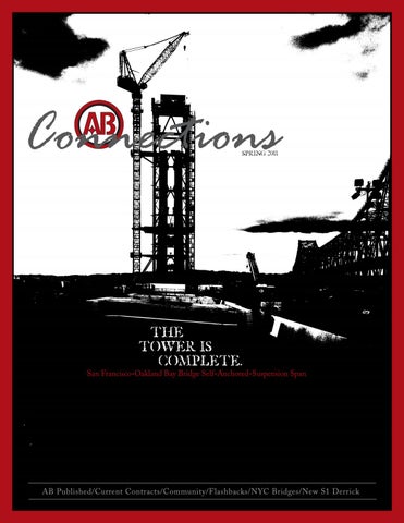
Connections SPRING 2011
THE TOWER IS COMPLETE.
AB Published/Current Contracts/Community/Flashbacks/NYC Bridges/New S1 Derrick
AB Connections
San Francisco-Oakland Bay Bridge Self-Anchored-Suspension Span
1 SPRING ’11
Connections CONTENTS
SAS Tower
G RIN
SP
4 Connections SPRING 2011
THE TOWER IS COMPLETE.
2011
highlight
San Francisco-Oakland Bay Bridge Erection Tower Hoisting System Tip Up Barge Geometry Structural Components Bolting Shaft Field Splices Successful Completion
San Francisco-Oakland Bay Bridge Self-Anchored-Suspension Span
AB Published/Current Contracts/Community/Flashbacks/NYC Bridges/New S1 Derrick
AB Connections
2 Current Contracts 1 SPRING ’11
C
O
V
E
R
Many have been anticipating this moment since the start of construction on the Bay Bridge in 2006 - the tower’s completion. Without a crane in existence able to pick 700T pieces, the team developed innovative erection procedures.
3 11
12
t h a n k y o u Much appreciation to the following individuals for their contribution to this issue:
14
Ugo DelCostello Paul Fikse Nick Greco Joe Grygiel Jonathon Hart Bob Kick Josh Perry Mark MacDonald Andre Markarian Mike McCoy Daniel McNichol Kara Mullin Scott Yeager
15 16 18
New Hires Updates from Human Resources Community Walt Whitman project team participates in local charity race Wellness Program Update NYC Bridge Projects Update Structural improvements in live traffic to the busiest bridge in the world New S1 Derrick at Headquarters AB increases it’s operative advantage by erecting this high capacity crane AB Published What bridges did AB build in it’s hometown? Flashbacks A 102 year old railroad high bridge and two vertical lifts Forth Replacement Crossing, Scotland FCBC Joint venture including American Bridge International awarded main contract for the new bridge spanning the Firth of Forth
12
14
15
16
AB Connections
18
2 SPRING ’11
by Kadi Camardese
Please contact the AB Communications & Marketing Department with news and inquiries: kcamardese@americanbridge.net
To receive AB Connections electronically or view archived issues visit: http://www.americanbridge.net/Media/newsletters.php
Current Contracts Manufacturing
Tampa
Huey P. Long Bridge Widening Fabrication, New Orleans, LA Estelle Pump Station Work Platform, New Orleans, LA Motor Parkway Bridge, Islip, NY Arawak Port Development, Nassau, Bahamas Alexander Hamilton Bridge, New York, NY Platt Street Bridge Major Repairs, Tampa, FL US 23 Grant Bridge, Portsmouth, OH Port Fourchon Bulkhead, Galliano, LA Walt Whitman Bridge, Philadelphia, PA Red Bug Lake Road Pedestrian Overpass, Oviedo, FL JR Taylor Memorial Bridge, Bethel Park, PA international PJ McArdle Viaduct, Pittsburgh PA Forth Replacement Crossing, Scotland, United Kingdom Bedford County Turnpike Girders, Bedford, PA Clearfield County Plate Girder Bridge, Kylertown, PA Richmond Willamette River Jasper Bridge, Springfield, OR Chesapeake Bay Bridge Redecking, Annapolis, MD Pony Truss Reinforcing Angles, Anchorage, AK Chincoteague Bridge, Chincoteague, VA Auxiliary Surface Buoys and Tow-Out Lugs, Reedsport, OR Pier R3 Repairs, Yorktown, VA Shore Parkway, Queens, NY Pier 31, Groton, CT Cochran Mills Bridge, Armstrong County, PA Bulkhead at NOAA Marine Operations Center, Norfolk, VA Sun Valley Bridge Widening, Los Angeles, CA M-140 No. 2 Complex, Portsmouth Naval Shipyard, Kittery, ME Three Nations Bridge, Cornwall Ontario, Canada Western ABFJV Oakland Bay Bridge, Oakland, CA new york
Pittsburgh
Kentucky Lakes Bridges, Grand Rivers, KY Coosa River Bridge, Clanton, AL Charleroi/Monessen Bridge Replacement, Charleroi, PA
Throgs Neck Bridge Structural Retrofits, New York City Bronx Whitestone Bridge Structural Retrofits, New York City RFK Triborough Bridge Structural Retrofits, New York City Walt Whitman Deck Replacement, Philadelphia, PA George Washington Bridge Rehabilitation, New York City Ogdensburg-Prescott International Bridge Main Span Rehabilitation, Ogdensburg, NY
New Hires Jared Carlson, field engineer, Special and International Projects, Headquarters, Coraopolis, PA Charlie Eure, crane operator, Arawak Cay, Tampa District, Tampa, FL Teresa Urick, system coordinator, Accounting Department, Headquarters, Coraopolis, PA Glenn Lindh, estimator, American Bridge Manufacturing, Reedsport, OR
Updates from Human Resources 401k Program
All salaried and hourly non-union employees can enroll in the American Bridge Company 401k program at any time and may also change the percentage being deferred throughout the year. If you would like an enrollment packet or you need a savings form to update your contribution percentage, please contact the HR (Human Resources) department at 412-631-1000. Effective as of April 2011, United Concordia will only be mailing Explanation of Benefits (EOB’s) that include a payment to you or that shows that your benefit plan did not cover your claim in full. You will no longer receive an EOB when a claim is paid in full. Members can continue to view all EOB’s on the United Concordia website, including those we are no longer mailing. To do so, a member would: 1. Go to www.UnitedConcordia.com and enter the ‘Members’ section 2. Select My Dental Benefits and sign in or create an account 3. Click on Claims & Deductibles and select the EOB for the appropriate claim Please keep in mind that as the policy holder, you can only see information for your dependents that are under the age of 18; otherwise they will have to create their own United Concordia log-in.
AB Connections
United Concordia is Going Green
3 SPRING ’11
SAS
Image: Tom
Paiva, 2011
Tower Completion
Article contributors: Bob Kick, operations manager Mark MacDonald, tower project manager Nick Greco, senior design engineer Scott Yeager, project engineer Andre Markarian, field engineer Daniel McNichol, field engineer Paul Fikse, Jr., design engineer
The self-anchored-suspension span of the new San Francisco/Oakland Bay bridge is the only one of its kind with a 1,400m (4,600’) long, 800mm (31.5”) in diameter main cable running continuously from east deck to anchorage to tower top to west deviation anchorage back to tower top and back to east deck anchorage.
AB Connections
The single tower portion of the project began in the summer of 2010. Since there is no crane existing today that is able to pick a 700T piece to the top of this massive tower, American Bridge/Flour Joint Venture (ABFJV) has developed special erection procedures which are the subject of this article.
4 SPRING ’11
The tower consists of four independent shafts, each made up of four field spliced segments referred to as ‘lifts 1 through 4’, which are interconnected by shear link beams (struts) and crossbraces. The shaft weights range between 1,100mt (metric tons) (1,213 tons) and 450mt (497 tons), with final lengths ranging between 48m (meters) (157’) and 33m (108’). Each shaft is capped by a single built-up, fabricated piece referred to as the ‘tower grillage’ (or lift 5) and finally, the tower’s supporting element for the suspension cable, called the ‘tower saddle’ (or lift 6). The tower grillage and the tower saddle each weigh approximately 450mt (497 tons).
ERECTION TOWER
The tower is equipped with a 65mt (72 ton) selfclimbing tower crane at its north side, which was used to construct the tower itself as well as miscellaneous components of the T1 tower and act as the general support crane used for erection. The tower crane stands at a height of 110m (361’) above its support platform (169m or 555’ above sea level) and is braced into the erection tower at four locations along its height that coincide with the four shaft field splice work platforms. These splice work platforms accomplish a dual purpose serving as a diaphragm bracing system connected to the permanent T1 tower, which in turn is used as the erection tower’s main lateral support system during construction.
Image: Tom Paiva, 2011
The erection tower was constructed in four major stages corresponding to the erection stages of the permanent T1 tower lifts 1 through 4. It was always built higher than each of the four permanent T1 tower lifts in order to hoist them into place using a 1,320mt (1,455 ton) capacity strand jack hoisting system. Designed with a chevron brace configuration on three of its sides with the fourth side (east face) kept open, this temporary tower allows the hoisting system to translate the permanent tower segments into place
utilizing two latticed columns. Additionally, the erection tower provides workers safe access to the permanent T1 tower via a personnel hoist and stair tower located on the south face supported by a platform at the 59m (194’) elevation, cantilevering above the eastbound permanent roadway section.
Deviation saddle (lift 6)
AB Connections
In order to construct the tower, ABFJV designed and fabricated the T1 erection tower and the T1 erection tower hoisting system. The 161m (528’) erection tower is temporary and surrounds the perimeter of the permanent T1 tower, sharing the same foundation. The main purposes of the erection tower are to support the hoisting system and a tower crane as well as to provide access to the exterior of the T1 tower during construction.
5 SPRING ’11
HOISTING SYSTEM
Lift 1 erection: west view of hoisting system from runway girders
3
4
1 2
AB Connections
1
6 SPRING ’11
runway girders
2
propped cantilever
The hoisting system was designed specifically to place permanent tower lifts 1 through 6 into final position. Staged on two runway girders supported by a propped cantilever, the system is able to raise permanent tower lifts from the east side of the tower foundation. Two 660mt (727 ton) strand jacks are used to raise and lower each permanent tower lifts into final location. The strand jacks each utilize 55 prestressing strands (0.6”) at their maximum capacity, have maximum stroke of 16” and a cycle time of 96 seconds per stroke. Once the lift is raised to its approximate final elevation, the system provides translation in both the eastwest and north-south directions via two separate sets of ‘gripper jacks’ connected to roller bearings. These jacks grip the top flange of their respective T-1 erection tower beam using a fulcrum-jack mechanism and a separate push-pull jack connected to the roller bearings to maneuver the system eastwest or north-south. The roller bearings range from 400 to 800mt (441 to 882 ton) capacity.
3
strand jacks
4
gripper jacks
The ends of the two sets of 55 strands are each secured to a custom designed lifting hitch which is pinned in to the upper tri-plate of the tower shaft rigging arrangement. This arrangement consists of the upper tri-plate, a 1,250mt (1,377 ton) swivel to provide rotational manipulation of the tower lifts for final alignment and placement, the lower tri-plate, 600mt (661 tons) synthetic grommets with 600mt shackles at each end, a 1,250mt (1,378 ton) custom designed adjustable spreader beam, and two sets of linked 600mt shackles. The shackles eventually connect the spreader beam into lifting lugs bolted into the top end of the tower lift field splice holes. Prior to the lifting operation, strand jacks are used to lower the tower shaft rigging arrangement to approximately 3m (10’) above water level where the linked shackles await the arrival of the tower lift, in a horizontal lay down position, supported on the tip up barge.
TIP UP BARGE
Lift 2 tip up operation: overhead view of tower shaft rigging
pound line pull W was reaved to the pin transfer cart to provide 100,000 pounds of restraint during the tip up operation. The longitudinal rails consist of a reinforced concrete runway; one with an embedded channel and the other with an embedded plate. The pin transfer cart rolls on a total of eight 300mt capacity roller bearings, four of which are guided and the others remaining free. These rails were located to coincide with the longitudinal bulkheads of the tip up barge. When the lift center of gravity approaches the center of rotation (approximately 80 degrees), the tipping point is transferred from the tipping pin to a rocker plate mounted on the pin transfer cart.
Once the rigging arrangement is connected to the tower shaft lifting lugs, strand jacks are used to raise the tower lift to a vertical position from its top end. The bottom end hinges on the tipping pins move horizontally along two longitudinal rails on the tip up barge via the pin transfer cart. A 50,000
Tip up cart configurations used for lifts 1 and 4
AB Connections
A detailed live ballasting plan of the barge is executed After during the tipping process to maintain a trim of plus extensive or minus one degree as the pin transfer cart moves structural and longitudinally along the barge. The largest load imparted stability analysis, ABFJV on the tip up barge was approximately 580mt (640 tons) engineers determined the best during the tip up of lift 1. Two 3,000 GPM (gallons per suited barge to perform the heart of the minute) pumps, positioned port and starboard of the tower lift erection procedure (fit up operation) barge, are used to transfer water between ballast tanks would be 210’ (64m) long by 68’ (20.7m) wide, to maintain the proper barge trim as the load transfers and 13.5’ (4.1m) deep. Several other barges longitudinally along the barge. within the ABFJV fleet were analyzed for overall global structural capacity (i.e. bending and Once the shaft reaches a vertical orientation, the shear), localized structural capacity (i.e. internal tipping lugs are unbolted from the bottom. The bulkhead strength and buckling), floating stability, strand jacks continue to raise the tower lift to an and optimal ballasting compartments for six major elevation to clear the field splice plates which are stages of the tower tip up operation for each of the staged on the previously erected tower lifts, or four tower lifts. the tower base anchor rods in the case of lift 1. The tower lift is then translated to the west The tip up barge, supporting the horizontal tower and either to the north or south. Air tuggers lift, is secured to the east side of the permanent connected to tag lines are used to rotate the tower pier and is orientated so that its length is tower lift (via the 1,250mt swivel) into its running parallel to the bridge centerline. As the final orientation. The strand jacks then lower barge’s elevation fluctuates from tide during the tip the tower lift onto the previously erected up operation its aft end is pulled in tight against the tower lift, or pier in the case of lift 1. The pier T1 foundation using sheave blocks and cables, and complete process from horizontal storage rests against six meter (20’) tall rub rails which maintain to final in place position of the lift 4 shafts support. takes approximately 17 hours (two and a half hours from horizontal to vertical on When the tower lift is on the tip up barge in the the tip up barge). horizontal position its top end is supported on timber mats, and its bottom end by two tipping lugs bolted into the bottom end of the tower lift. The tipping lugs are connected to a tipping pin that rests on the pin transfer cart.
7 SPRING ’11
GEOMETRY
AB Connections
The contract tolerances for the tower geometry are extremely tight, and to ensure they were met the tower was vertically assembled in the ZPMC fabrication facility successively. The tower centerline is must be vertical to within 1:2500 and the field splices between the lifts are required to meet milled to bear criteria and, in the case of field splices 1 through 3, were fully drilled in the shop. This meant that there was essentially no ability to adjust the tower for vertical alignment at the job site. Furthermore, each of the struts and crossbraces were drilled to the alignment established during vertical assembly in the shop making horizontal alignment critical. Therefore it was imperative to vertically and horizontally align each individual shaft to the fit up geometry achieved in the fabrication shop.
8 SPRING ’11
To accomplish the fit up geometry, ABFJV utilized four single acting vertical jacks around the perimeter of each shaft, pushing up against a bracket extension bolted into the tower shaft, to raise and tilt the towers to achieve vertical alignment. Seven horizontal jacks were staged within each tower shaft to align them horizontally in the north, south, east and west directions.
Survey shots taken at the base and the top of each tower shaft were imported into Auto CAD software where ABFJV engineers manipulated them to determine the required vertical and horizontal jack strokes necessary in bringing the shafts into alignment. A synchronized jacking system was used for the vertical jacks to ensure that each was carrying its predetermined load share while tilting and raising the tower shafts to prevent overload. These jacks were also equipped with a locking collar so they could be released from the hydraulic pressure once vertical alignment was achieved. A mechanically locked PTFE (Polytetrafluoroethylene) slide bearing and stainless steel was used at the jack plunger and bracket interface to reduce the coefficient of friction to less than five percent, resulting in less than 55mt (60 tons) of force pushing the 1100mt (1212 ton) tower shafts horizontally. ABFJV was able to position each lift 1 tower shaft to within 3mm (millimeters) of the fabrication fit up as-built survey using four iterations of survey shots and jack movements. Based on the in-place survey at the top of lift 4, the tower centerline was vertical to within 1:5385 and within 8mm (5/16�) of design elevation.
Tower shaft horizontal alignment operation: view of horizontal jacks and jacking bracket set up
STRUCTURAL COMPONENTS Tower Cross brace: installation at elevation 53m (174’)
Lift 4 strut and facade elevation: facade tops removed for bolt-up access
Following the alignment of lift 1 shafts, the four independent tower legs are interconnected by two structural components - the struts and the crossbraces. The struts resemble a stiffened builtup beam and are designed to absorb the energy of a seismic event through inelastic shear deformation before the tower shafts experience any damage.
The six struts join the four shafts at 20 tower elevations. They are approximately 1m (3.28’) deep, weigh up to 3.8mt (4.2 tons) and are enclosed by architectural components called facades. The connections for the facades to the tower contain slotted holes and PTFE at the faying surfaces to allow the shafts to move independently during a potential seismic event. The struts are such a critical component that 68 replacements were provided by ABFJV to the owner in the case that any experience seismic damage.
The crossbraces join the shafts at eight elevations in the shape of an X, approximately 3.6m (11.8’) across and weighing 2.1mt (2.3 tons). They act in both a tension and compression. The braces connect to a spherical bushing bearing on each shaft via 170mm (7”) diameter pins. These bushings are designed to resist a 1.5MN (mega newton) (169 ton) radial load and the connection permits the cross brace to rotate up to five degrees, allowing the towers to act independently during a seismic event but maintain a certain degree of alignment.
All components, struts, facades and crossbraces are erected from material staging barges or the roadway deck. In this case it is not the size of the components that make the work challenging, but rather, the internal and external geometry of the towers, compact working areas and tight bolt clearances which demand detailed erection and bolt-up procedures. At any given elevation the crossbrace must be erected first, followed by a specific strut and facade erection sequence. Splice plates for the struts require a specific staging pattern to allow room for strut erection. All strut, crossbrace and facade elevations for a tower lift must be erected prior to erecting the successive lift. Finally, a specific strut and façade bolt up sequence must be followed in order to avoid bolt installation and tightening clearance issues.
AB Connections
Specific struts provide lateral stability for the tower and erection tower during construction, requiring their specific elevations to be fully bolted prior to beginning erection of the next stage. The remaining elevations of struts, not required by construction analysis to advance erection for the subsequent stage, will be completed by crews at a later time - off of the critical path of tower construction. The struts are connected by both flange and web splices to internal tower diaphragms and exterior skin plates. Depending on the location, an elevation requires anywhere from 1800 to 2400 M30 A490M bolts ranging from 140 to 260mm (5.5 to 10.2”) in length. There are an average of 3700 bolts required at each strut elevation.
9 SPRING ’11
BOLTING SHAFT FIELD SPLICES
The erection of tower lift 2 brought a new element of the work: bolting the shaft field splices. Each tower shaft consists of five sides (skins) that are reinforced by as many as 21 longitudinal stiffeners. While three of the skins are vertical, the other two slope, which causes the cross section of each shaft to decrease as the tower rises. The skins range from 60mm to 100mm in thickness, and longitudinal stiffeners range from 50 x 195mm to 70 x 470mm (18.5”). The adjoining tower shaft skins are milled to bear and field spliced together with interior and exterior bolted splice plates. These splices consist of up to 400 plates (100 per shaft) and 28,240 M27 diameter A490M bolts (7,060 per shaft) and vary in length between 200 and 280mm (7.9 and 11”). In total, there are 87,208 bolts in the four field splices.
Pins and centerhole jacks are installed on two of the tower skins in order to complete the phase 1 bolting of the connection; further allowing the rigging to be disconnected from the top of the tower lift
Overhead view of the top of tower lift 1 prior to setting down lift 2: tower skin interior and exterior splice plates can be seen as well as the internal longitudinal stiffener splice plates
Once the shafts are set in their permanent location, the field splices must be bolted in phases to allow construction to advance. The first phase takes place right after the shaft is set and consists of installing a minimum number of bolts (approximately two percent of the connection) to allow the rigging to be disconnected. At this time, pins are installed along with centerhole jacks that clamp splice plates on two of the vertical skins. The pins, in conjunction with the clamping force, recreate the shop fabrication geometry and allow the installation of the phase one bolts. The second phase installs approximately ten percent of the connection to seismically secure the partially erected tower, and to allow further erection and bracing of the temporary erection tower. The third and final phase completes the connection.
AB Connections
ABFJV has completed the erection of lifts 1 through 4 by successfully executing a complex procedure that consisted of tipping 16 individual T1 tower lifts from a horizontal position on a floating barge and hoisted them and translated the lifts to their final in place position at a maximum lifting height of 166.6m (546.6’). Tower saddle erection and completion of the permanent T1 tower is anticipated for May 2011.
10 SPRING ’11
Image: Tom Paiva, 2011
SUCCESSFUL COMPLETION
Walt Whitman Project Team Participates in Local Charity Race
Participants: Several AB employees working on the Walt Whitman Bridge Suspension and th 5K run Anchorage Spans Deck project participated in the 16 Annual Dash for Organ th Bill Batzel, field engineer & Tissue Donor Awareness event on Sunday, April 17 , 2011. The race began at Mike Hartranft, field engineer Philadelphia’s renowned Museum of Art and continued parallel to the city’s scenic Kara Mullin, field engineer Schuylkill River. All donations benefit future awareness and support of the cause. Dan Murphy, project manager Kara Mullin, AB field engineer, who Zach Osei, field engineer organized the race for American Bridge Joe Stilson, field engineer explains, “The weather was perfect. It was Jillian Thornton, guest about 65 degrees and sunny, with a light Jimmy Thornton, project engineer wind. Everyone did really well and looked 10K run good doing it (in matching T-shirts)! The Bill Curran, guest big winner out of the AB group was Jimmy Lori Gross, guest Thornton, running the 5K (kilometer) in Lindsey Hanson, guest 22:15, at a 7:11 per mile pace.” 3K walk For information and results, please visit: http://2011dash. kintera.org/faf/home/default.asp?ievent=460816.
Left to right: Jim Thornton, Zach Osei, Mike Hartranft, Bill Batzel, Dan Murphy, Jillian Thornton, Kara Mullin, Joe Stilson
Gayle Keyes, guest Mark Keyes, ironworker foreman
It is never too late to start participating in the wellness program. If you are a new employee or one who has been recently re-hired and have missed out on a few of the month’s initiatives, you can still participate at your own pace. If you would like to try the Move it to Music challenge just contact the Human Resources Department (HR) and we can send you a kit. Please remember that in order to receive your wellness points for this challenge, you must return your completed Move it to Music log book to HR. It is important to mention that each month we will send out correspondence and focus on one or two of the items from your wellness points checklist. Please note that not all items on the checklist will be focused on – you must take the initiative to complete some of the goals yourself. Most of the items can be accomplished at your own pace and can be done at any time throughout the year. We welcome any and all suggestions. Just send a quick email to Kathy Bonetti at kbonetti@americanbridge.net with your ideas. April In April our focus was the online wellness profile through Highmark. This assessment will help you understand what steps you can take to improve or maintain your health by creating a personal healthy lifestyle plan customized to your individual needs. It also provides valuable information that you can share with your personal physician. Your privacy is very important and this assessment is completely confidential, adhering to all HIPAA (The Health Insurance Portability and Accountability Act) regulations. If at any time you are uncomfortable completing a question, you may skip over to the next. If you completed this online assessment last year, you can do it again for 2011 and earn additional wellness points. Please note: if you do not have medical insurance through American Bridge Company or access to a computer, please contact HR and we will arrange for you to complete a paper version of the wellness profile. May The wellness initiative for May is Strides for Health, which is an eight week, self-guided walking and physical activity challenge. In order to receive your wellness points for completing this, you must return your completed Strides for Health log book received at the beginning of the program to HR. You can also receive wellness points in May for participating or volunteering in a walk/run-a-thon. Just take a wellness goal completion certificate to the event and have one of the coordinators sign it. June In June we will kick off the second newsletter campaign of 2011, called Maintain Your Mind. This is a six week health education campaign designed to help you learn what steps can be taken to preserve and promote brain health. You will receive a weekly email (or paper copy) with topics that include helping you evaluate your lifestyle habits and how they may impact brain health. You will receive ten wellness points for signing up for this newsletter campaign. Color Your Plate Newsletter Raffle Winner Congratulations to Dave Partazana of American Bridge Manufacturing in Coraopolis, Pennsylvania for winning the $50 grocery store gift card!
AB Connections
Wellness Program Updates
11
SPRING ’11
NYC
project update
by: Jon Hart, AB project manager
American Bridge Performs Structural Improvements to New York City ’ s Historic Bridges
In February, 2011 American Bridge completed the structural improvement project on the Robert F. Kennedy Bridge (RFK; formerly known as the Triborough Bridge). This was the last in a series of three similar New York City contracts for owner MTA Bridges & Tunnels (MTA). The second was completed in June of 2010 on the Bronx Whitestone, a bridge originally built by AB in 1939 and on which the company has undertaken several previous rehabilitation projects. The Throgs Neck Bridge was completed in December of 2009 and is one of twelve major roadway bridges constructed by American Bridge in the New York City area. The subject of this article is the most recently completed structural improvements project – the RFK Bridge. The RFK Bridge carries 150,000 vehicles daily on I-278 between the New York neighborhoods of Queens, Bronx and Manhattan. AB’s work on the bridge required retrofits to 186 suspender rope groups, 1,100LF (linear feet) of main cable, and installation of 550 tons of new structural steel. Most work was completed during the day, between rush hours to minimize traffic impacts. Overnight lane closures were necessary when overhead work was preformed requiring larger cranes, and in turn, necessitating multiple lane closures.
AB Connections
Before work on the project began, the MTA approached AB to discuss alternatives to the installation of temporary concrete barrier on the bridge. The original plans provided a small aroundthe-clock work area, but not ample space for equipment. Moreover, the work area would have reduced the lane widths from an already narrow 10’6” configuration. To improve traffic flow and public safety throughout the course of the work, American Bridge and MTA worked together optimize procedures that minimized traffic disruption, maximized traffic safety and increased the productivity of construction operations. This was accomplished through developing alternates by assessing and identifying impacts on productivity and schedule as well as the specialized equipment that would be required.
12 SPRING ’11
The short-duration closures and specialized equipment such as 15 ton cranes, platform lift trucks, specific rigging and specially outfitted
trailers for materials made careful work planning a necessity. Equipment layouts and assignments, truck loading and erection sequences, traffic protection and crew assignments were developed carefully in advance and often had to be modified if traffic conditions prevented work in particular locations. Every operation had two or three preplanned alternates in order to accommodate these changes. Much of the erection work from the roadways was performed with 15 ton Tadano cranes, which offered a small space footprint and were able to operate on outriggers in as little as 6’7”. These were combined with sufficient boom lengths and capacities to set all but the heaviest pieces, which were placed at night with a larger 45 ton crane. American Bridge worked cautiously during the detailing phase to locate all splices, minimizing the number of pieces requiring night closures and maximizing use of lanes when closure was essential. The project required the reinforcement of the bridge anchorages, located underneath the roadway deck. This work was even more challenging than that of the roadway. Working from inside the anchorages starting at ground level deck, American Bridge crews threaded steel plates measuring 90’ horizontally and 85’ vertically and weighing 8000 pounds into the anchorages, all while maneuvering through and around the roadway and cable saddle supports and the anchorage wind pins.
This required extensive advance planning and engineering. The method chosen involved installation of temporary cableways and runways, and required carefully choreographed use of tugger hoists, Hillman Rollers, and chain falls to maintain proper orientation throughout every stage until the plates reached their final location while not damaging the hot-dipped galvanized coating. Due to the tight space, the plates had to be rigged in a specific sequence and could not be flipped or turned to reorient after they had reached certain points in their paths. American Bridge’s subcontractors upgraded and relocated the electrical systems, installed fencing on the structure and at grade, performed abatement and surface preparation of the existing structure, painted the new steel and installed a dry fire standpipe along each side of the length of the suspended structure. With all major portions of the contract complete, American Bridge continues with minor closeout work. The company will complete six-month, 18-month, and 36-month performance evaluations on many of the components installed; similar inspections which have been ongoing at the Throgs Neck and Bronx-Whitestone projects.
Special recognition goes to all who had worked to make all three projects successful: New York Office Kwadwo Osei-Akoto, vice president Miguel Lo, office manager Pete Bereza, safety manager Throgs Neck Bridge Bruce Phillips, field engineer Zach Rosswog, field engineer Bronx Whitestone Bridge Mike Hartranft, field engineer Zach VanLemmeren, field engineer RFK Bridge Jon Hart, project manager Mike Comstock, field engineer Chad Ford, field engineer Zach Lauria, field engineer Bruce Phillips, field engineer Throgs Neck Bridge and Bronx Whitestone Bridge Dan Murphy, project manager Jim Thornton, project engineer RFK Bridge and Bronx Whitestone Bridge Dan Sheehan, field engineer Throgs Neck Bridge and RFK Bridge Josh Perry, project engineer Throgs Neck Bridge, Bronx Whitestone Bridge and RFK Bridge George Terrance, superintendent Angus Adams, superintendent American Bridge Manufacturing, Coraopolis, PA Brian Furman, Larry Smith, George Givens and Pat McCarthy For their provision of drafting support and fabrication of structural steel for the Bronx-Whitestone and RFK projects
American Dock & Transfer, Coraopolis, PA Joe Grygiel
For coordinating the delivery of materials to the sites within project schedules and the limited laydown and storage areas
American Bridge Company Engineering Department, Coraopolis, PA Stanley Walker, Win Patchell and Carl Schwarz
AB performs structural improvements to the RFK Bridge during live traffic; the bridge carries 150,000 vehicles daily
AB Connections
For their support to the projects, particularly with engineering rigid temporary shielding platforms that were installed over traffic at RFK (also fabricated by American Bridge Manufacturing)
13 SPRING ’11
S1 derrick
headquarters
The 40 ton capacity 1500 Favco assembled by American Bridge forces in January of 1998 has recently been replaced by a 120 ton S-1 Derrick, providing AB with an increased operative advantage. Located at the company’s private property, approximately ten miles northwest of Pittsburgh, Pennsylvania the new crane rests on the bank of the Ohio River, making for quicker material transports at a lower costs. 12-2 12-20
Upper pile driving
1-18
Filling piles with concrete
1-24
First derrick sill erection
Stand up and dress mast
3-08
American Dock & Transfer Richard Beight, mechanic John Davis, mechanic John Gerace, fabrication foreman Joe Grygiel, yard superintendent Jim Hall, welder Mark Lind, laborer Richard Mayer, painter Mike McCoy, foreman Richard McCoy, operator Jim Miller, mechanic Nate Patton, laborer American Bridge Company Bill Felker, operations manager Ugo DelCostello, general superintendent Any Kerr, superintendent Mike Wade, superintendent American Bridge Manufacturing Bob Cook, welder Dennis Hillebrand, welding quality control Tom Makiush, welder Dave Ward, welder
erection timeline
1-25
The following American Bridge employees extended considerable efforts to erect the new derrick from December of 2010 until its completion in March 2011:
AB Connections
Install 35 kip hoisting engine
14 SPRING ’11
3-04
2-22
Leg erection
Completed derrick Installing boom and reeving the mast
AB
published As Walter C. Kidney composed his book Pittsburgh’s Bridges, he called upon American Bridge to acquire archival information about the city’s bridges. As it turned out, he came to a good source since of the hundreds of bridges covered in his book, over half were built by American Bridge. The late 1800s and early 1900s represents an active period in the development of the City of Bridges, which is explained in the book as well as later development that resulted in the construction of the Fort Pitt, Fort Duquesne, Neville Island and Veterans Bridges (all built by American Bridge). Kidney does a thorough job of exploring the influence of Pittsburgh’s Art Commission on the design of many of the most prominent of the region’s 1,900 bridges. This commission was charged with establishing the bridges in the area as attractive sculptural components of the fabric of the city. Pittsburgh area residents and visitors continue to benefit from the commission’s excellent work today. The region’s structurally unique and beautiful bridges do not compare with the scale of the bridges in New York City, for example. However, they remain gems that have even further enhanced the city’s developing architectural mosaic that has accompanied environmental cleanup and new building development that have occurred in the regions several modern renaissance periods.
Andy Warhol Bridge (Seventh Street) Fort Pitt Bridge Fort Duquesne Bridge Manchester Bridge Neville Island Bridge (Interstate 79) Rachel Carson Bridge (Ninth Street Bridge) Robert D. Fleming Bridge (Sixty-Second Street Bridge) Roberto Clemente Bridge (Sixth Street Bridge) Tenth Street Bridge West End Bridge Veterans Memorial Bridge Sewickley Bridge
AB Connections
American Bridge is proud to have called Pittsburgh its home for nearly 110 years, and to have played a leading role in the construction of its many bridge structures. Shortlist of American-Bridge-Built-Bridges in Pittsburgh, Pennsylvania:
15 SPRING ’11
11
George Washington Bridge Hanger Replacement Location: New York City AB order no.: 490110 Project manger: Leo Kupiac Superintendents: Tommy Gibson and Danny Dunn Office manager: Miguel Lo
f la shba cks
For the past 110 years AB has been emblematic in the building many of New York City’s iconic bridges, and with dozens of area projects undertaken just in the last ten years the company’s presence there remains prominent. One of AB’s many current NYC contracts is the replacement of the George Washington Bridge deck at the expansion joints with new orthotropic panels. The George Washington Bridge (GWB) is the busiest bridge in the world, with over 285,000 vehicles crossing it each day. Within the past 15 years alone, American Bridge has successfully completed over six contracts on this NYC Hudson River crossing, all without full or partial traffic closure.
One of the more interesting GWB projects was completed in 2000, when American Bridge handled the field construction aspects of a comprehensive inspection program for main and suspender cables. The work involved replacement of six hanger ropes, so as to allow destructive testing of the removed cables. The variety of locations of the rope replacements dictated a different method for each case, the engineering for which was done by American Bridge. This experience has served American Bridge well – as the company has gone on to replace the ropes on numerous suspension bridges, including Lions Gate (Vancouver), RFK Triborough (New York), Verrazano (partial – New York), Anthony Wayne (Toledo) and Angostura (Venezuela). Sections of the main cables were also unwrapped, wedged, inspected and rewrapped. This required the design, fabrication and erection of an enclosed work platform on the cable.
24
Sunshine Skyway Bridge Location: St. Petersburg, FL AB order no.: W-2001 AB employees: Senior managers: Robert Holmberg, Duane Brautigam and Paul Smith Construction procedure engineers: George Kerrick and Ted Gish Field engineers: Andrew King, John Schober and John Lutz Erection superintendents: Red Kelly, Pete Petersen and Doty Grieder Water equipment superintendent: Larry Tatum
The Sunshine Skyway Bridge is an iconic structure in the Tampa Bay area of Florida, across the United States and throughout the globe. The modernly designed structure spans the emerald green waters of Tampa Bay connecting St. Petersburg in the north and Terra Ceia in the south. Construction took place over the major ocean shipping channel that is the entrance to the Port of Tampa and numerous other ports and marinas around the bay. The roadway deck is 175’ above mean high water. American Bridge was part of a joint venture with Paschen Contractors and Morrison Knudsen Company that was general contractor for the construction of this 8,858’ precast segmental bridge consisting of three major parts: one, 4,859’ of twin, 43’ wide segmental roadways with typical 135’ spans, erected by the span by span method; two, 1,720’ of single, 85’ wide high level post tensioned concrete segmental roadway of typical 240’ spans, was erected by the launching girder method, and three, a 2,280’ by 85’ wide precast segmental cable stayed main bridge with a 1,200’ main span, erected by the balanced cantilever method, with a single plane of site-fabricated, steel tube enclosed stays.
16
This bridge replaced the existing twin truss bridges carrying traffic over the Tampa Bay, until being demolished in 1980 after the southbound bridge was struck by a freighter and partially collapsed. Both of the original bridges were fabricated and erected by American Bridge (the first in 1954 and the latter in 1971) and were two-lane, 5,621’ long, 31-span crossings; including twelve 100’ and twelve 140’ deck plate girder spans, four 289’ deck truss spans, and a three-span cantilevered through truss of 360’+864’+360’.
SPRING ’11
AB Connections
AB Connections
The stays were fabricated, erected, and tensioned by American Bridge. The towers are hollow box, post tensioned, precast segmental concrete balanced cantilever erection was by four hoisting engines, two at each tower location, and purposebuilt lifting gantries. Stay cables were fabricated on the bridge deck. Steel tube enclosures were erected first, supported from the stay cable below by specially designed ‘bicycles’. Cable strands were cut to length on the bridge deck, fitted with a lifting eye, and pulled through the already erected tube, over the banana pipe saddles in the towers, and through the tube on the other side of the tower. Stays were tensioned at both ends by an articulating jack array. Deck sections were post tensioned with Dywidag Bars.
16 SPRING ’11
Norfolk Southern Kentucky River High Bridge Location: Jessamine and Mercer Counties, KY AB order no.: B-5360-2
This project involved the construction of a new 1,059’ double-track deck truss, with three spans of 353’. While trains continued to run full-service on the old truss, the bridge was erected around the existing 1877 iron structure; the new towers surrounding the old ones. The new truss, at 73’ high, was 31’ taller and wider than the 18’ wide original. The bridge deck is 280’ above normal water elevation. AB’s customers for this project were Cincinnati, New Orleans, and Texas Pacific Railway, which was part of the Southern Railway System. In 1985, the ‘High Bridge’ was named Historic Civil Engineering Landmark by the ASCE (American Society of Civil Engineers) and is currently owned by Norfolk Southern Railway.
102
Bridge for Marine Parkway over Rockaway Inlet AB employees: D.M. Wood, superintendent and E.E. McKeen, field engineer Location: Brooklyn, NY AB order no.: G6570-87
74
This project involved the construction of a new vertical lift bridge and its associated machinery, to provide easier access to the Rockaway Beaches in Brooklyn, New York. From January of 1936 to July of 1937 the project’s construction was recorded under 16 detailed AB order numbers. While American Bridge was erecting this 3,842’ structure and its 540’ vertical lift span, the average bridgeman’s rate was $1.65 per hour working about 40 hours per week. There are two approaches, four lanes of traffic, two 540’ truss spans and when in the open position clearance is 150’. The concrete for the counterweights was hoisted in a one yard bucket by derricks which erected the steelwork in the towers, and were poured by Corbetta Construction Company. AB erected one line of 1.5” conduit for the telephones on the south approach deck spans, south flanking spans and both towers from roadway to pier tops. There was an additional ¾” of conduit from the splicing chambers on the 97’ deck spans to abutments and on the towers from splicing chambers to telephones. One thru riveted truss vertical lift span (540’ center to center bearings square, 55’ center to center trusses, curved chord 60’ deep at center) was erected alongside the 55’ by 40’ by 193’9” high north tower on eight steel framework columns resting on two 10’ by 38’ by 325’ car floats. The falsework was composed of steel pile sections for the columns and bracing, the grillage being stringers from the span. The falsework was assembled on the car floats at Weehawken, New Jersey and on arrival at the site, the floats were properly spaced and the bracing placed between them. A 90’ triangular erection tower and an S2-type stiffleg derrick were utilized for the erection of the towers, rope and rope sockets; structural steel used to build the machinery operator’s and gate tender’s houses; sheaves, shafts, bearings; operating machinery for the operation of the lift span, barrier gates and end locks; roller guides and air buffers; and rope connections and deflectors. Eleven of the twelve 97’ to 213’9” fixed spans were erected on 30’ by 180’ car floats about four miles from the bridge site, and floated into place. The twelfth span was erected on timber blocking in place at the site. All spans have cast steel shoes. The falsework on the car floats consisted of four towers of four 12” by 12” legs each. The open grid roadway sections for the through truss and tower spans were erected similarly. American Bridge has worked on the bridge on two other occasions since its original completion. In 1981 AB made renovations to the bridge, including replacement of sidewalk steel, removal and replacement sidewalk deck, installation of new lighting system and refurbishment of locker room (P915BR). Then in 2009, American Bridge completed repairs, replacement of sway bracing, and reinforcements to the bridge in open traffic (467110).
Completed in 1960, this contract was for the construction of a double deck, vertical lift rail and highway bridge, with the single-track railroad on the lower deck and a four-lane roadway on the upper deck. The bridge carries US-41 and M-26 from Houghton to Hancock, Michigan. The railroad deck was designed to accommodate highway traffic when raised to the intermediate highway level, when small and medium sized watercraft passed underneath. In 1982, railroad service was discontinued and the lower deck now accommodates highway traffic for nine months of the year and for the remaining three months it is used for snowmobiles. The overall length of the bridge is 1,310’, with a lift span of 268’, and is supported by 180’ twin steel towers. The middle section of this four lane, vertical lift bridge has a four foot clearance when fully lowered, a 32 to 36’ clearance at the intermediate position, and 100’ when fully raised.
51
AB Connections
Project name: Portage Lake Lift Bridge Location: Houghton/Hancock, MI AB order no.: V-1662
17
SPRING ’11
PRSRT STD US POSTAGE PAID CORAOPOLIS, PA PERMIT NO. 7
1000 American Bridge Way Coraopolis, PA 15108 United States of America
by Kadi Camardese
Please contact the AB Communications & Marketing Department with news and inquiries: kcamardese@americanbridge.net
FCBC Joint venture including American Bridge International awarded main contract for the new Forth Replacement Crossing in Scotland American Bridge International announced that an international joint venture of which it is part has signed the main contract with the Scottish Ministers for design and construction of the Forth Replacement Crossing (FRC), which comprises a bridge over Firth of Forth in Scotland and the road connection immediately north and south of the 2.7 km bridge The contract is valued at £790 million ($1.3 billion). Following an 18-month competitive tender, Forth Crossing Bridge Constructors (FCBC) were named preferred bidder for the design/ build contract in mid-March of this year. In addition to American Bridge International (28% ownership), the FCBC joint venture comprises HOCHTIEF (28% leader), Dragados (28%), and Morrison Construction (16%). All four businesses have a solid record of successfully delivering major infrastructure schemes throughout the world and will jointly provide the full range of skills, resources and technical expertise for this complex project.
A major bridge crossing two ocean shipping and military navigation channels represents the main part of the contract. This bridge structure has an overall length of 2.7 km, including a cable stay structure of 2,020m (world’s second longest). The two main navigation spans are 650m each (world’s sixth longest). The bridge has 14 spans, three
concrete towers in the center of the transverse cross section up to 210m in height, two planes of stay cables that anchor in the center of the structure, and a composite steel tub/ concrete deck superstructure. The north and south tower foundations are excavated caissons up to 40m below the water surface, and the central tower is a direct foundation on a rock outcropping. The cable stay bridge superstructure will be erected mainly by deck mounted gantries. The South approach viaduct will be launched from land, and the north viaduct will be pushed from the water. Construction will begin in 2011 and be complete in 2016. American Bridge Company was founded in 1900, and specializes in the construction of complex structures and marine works. The company has participated in the construction of thousands of major bridges around the world.
Rendering image of the new bridge spanning the Firth of Forth in Scotland, UK
“We are immensely pleased to have won this major contract in a country famous for major bridges, and in association with our three outstanding partners.” said Michael Cegelis, Executive Vice President of American Bridge International. “It is a complex and iconic structure that will fully demand our unique technology.”