Spring 2010
Spring 2010
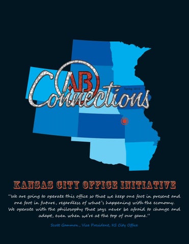
Prospects for the AB new midwest office are being compiled geographically across a wide geography including Missouri, Kansas, North Dakota, South Dakota, Iowa, Minnesota, Nebraska, Arkansas, Oklahoma, Colorado and Wyoming.
Much appreciation to the following individuals for their contributions to this issue: Eric Blue Kathy Bonetti Wayne Davis James DiPasquale Alex Fattaleh Mike Flowers Scott Gammon Dan Hester Bob Kick Simon Laming Dan McNichol Lanny Miller
Henry Mykich Adam Roebuck Sonya Rooney Anne Royster Katherine Quillin David Speakman John Schober Carl Schwarz Lou Wehar Robert Yahng Rick Zimmerman
Connections Newsletter
by Kadi Camardese Communications Manager American Bridge Company
American Bridge was awarded the Western Pennsylvania Associated Builders and Contractors, Inc. Award of Merit for their headquarters expansion on April 17th 2010. The project, completed in 2008, included the fabrication and erection of steel for a two-story addition to the main headquarters building, including training room, fitness center, conference facilities, office space, and archives. The architect on this project was L.F. Gilberti, and the owner was American Bridge. TUDI Mechanical performed both the plumbing and HVAC work and installed a web-based temperature control system. The award was accepted at the 37th annual Excellence in Construction banquet Joe Grygiel, who oversaw the project for American Bridge, and his wife, Karen.
Retiree Luncheon
Twice a year, American Bridge retirees meet over lunch to socialize and catch up on the company’s news at the First Presbyterian Church in downtown Pittsburgh, an historic landmark built between 1903 and 1905. There were approximately 30 in attendance for the April 20, 2010 luncheon. Many of them retired from American Bridge or have joined other firms, yet each share a passion for the great works they were involved with during their tenure with the Company. Dave Briskey recently toured the self-anchored suspension span of the San Francisco Oakland Bay Bridge, currently under construction by American Bridge / Fluor Joint Venture. He presented detailed highlights of his visit including video footage and images of the project. The event was coordinated by Bill Gibson until he turned 90 last year. Since then, it has been taken over by Bill Pascoli. Bill began employment with American Bridge upon college graduation. After 20 years of project management, estimating and design service in Pittsburgh, he moved on to become Regional Engineer for the American Institute of Steel Construction (AISC), the not-for-profit trade association representing structural steel in the U.S. The next luncheon is scheduled for late September 2010.
Spring ’10
.
Connections .
Page 3
Training
I
If you read Connections every quarter you know that we always include a section on American Bridge Field Engineer Training. For this issue Kadi Camardese (KD) thought you might want to hear some participant’s thoughts on the program – field engineers James DiPasquale (JD) and Simon Laming (SL) have been in the American Bridge training program for over two years and here is what they have to say:
KD: What do you feel is the greatest advantage(s) of the training program? JD: American Bridge has a rich history of building some of the world’s largest and most complex bridges. And with that is an abundance of resources and knowledge, particularly through the engineering department. Training provides access to that and for me personally it has been a huge advantage.
KD: Has the program encouraged you to think more innovatively? What is a specific example of this? SL: The training has encouraged me to think more innovatively by testing my problem solving skills on real projects, while under the guidance and supervision of highly experienced design, field, and management personnel from within the company. Running project means and methods simulations, whereby trainees challenge, question, and compete against each other has taught me when, where and how innovative thinking can benefit real projects.
KD: Do you have a mentor within the company? How has this encouraged you / enabled you to learn quicker? JD: Our QC Manager, Joe Tumas (on the project James is assigned to the Kentucky Lake Bridges) has been very influential. I’ve also worked a lot with our general foremen, Larry Tussey and Gary McDonald. Working with experienced people on-site is great for development of skills and knowledge of what we do from a constructability standpoint. SL: One of the helpful things about the training is that we are all assigned official mentors who not only act as go-to people for help and advice, but also take a responsibility in insuring that our progress is monitored and measured. As with most trainees, my mentor is my current project manager, whose availability and willingness to listen and teach is a vital component to my progression through the training program.
KD: What knowledge gained through the program has been most helpful in the field? JD: The opportunity to interact with people in the company not on your jobsite (as mentioned above). It’s much easier to talk with someone in engineering, accounting, or HR on the phone if you’ve already met them. You also get a better understanding of who does what in the main office, so you know who to call for specific issues. SL: For me personally it has been the valuable insight to the business side of things – having a better understanding of finances, management, clients and risk. While I am still a fair way from being directly involved in these aspects of work, the background knowledge helps to understand what is and isn’t possible when it comes to planning, scheduling and designing means and methods for a project, and when our teachers are the vice presidents, managers, and the CEO himself, we know that what we’re learning is real continued on page 10 and invaluable. Spring ’10
.
Connections .
Page 4
“what makes AB attractive is the family environment in a big company. The training program is an example of this. It promotes working and communicating with different people in the company you otherwise wouldn’t on your jobsite .” James DiPasquale
Training The session four field engineer training session was held at the American Bridge headquarters office in Coraopolis, Pennsylvania from April 12th through the 14th, 2010.
The curriculum included design drawings, scheduling, project handoff and mobilization, information technology policies and procedures, owner’s contract and project closeout. Additional presentations highlighting skills in communication, writing, safety, management and planning should prove to be advantageous to the engineers throughout their careers. The attendees and their current assignments: Michael Comstock Zachary Lauria Eric Blue Benjamin Crowder Troy Bodenschatz Kara Mullin Daniel Sheehan Ben Berardino Paul Fikse Matt Boos Tyler Luffy Bill Batzel
Chesapeake Bay Bridge RFK Triborough Bridge SAS Bridge Nassau Port Expansion SAS Bridge Chincoteague Bridge Whitestone Bridge Pier 31 SAS Bridge Castaway Cay Forth Road Bridge Replacement (tender), Scotland Pittsburgh (Estimating)
The Presenters:
The subject experts:
Written communications and technical writing, plus organization of a negotiating exercise Mike Cegelis Safety concepts Henry Mykich Labor management, personality profile and presentation communication skills Bob Chance Action planning & feedback Wayne Davis
Design drawings Stanley Walker, Larry Smith and George Givens Scheduling Dan Edwards Project handoff and mobilization, owner’s contract and project closeout John Schober IT policies and procedures Brent VanArsdale Spring ’10
.
Connections .
Page 5
Drop 10 in 10 Success Story
Drop op 10 in 10 Wellness Program began at the beginning of January and ran for 10 weeks. e It was a guided weight management and healthy lifestyle program. Employees were given a kit that included a guidebook, daily food and fitness journal, oy w tape m measure, r and resistance band. The Human Resources Department has received positive from many participants of the program who were able to make v feedback ed healthy changes. For example, David Speakman from American Bridge th lifestyle fe Manufacturing Oregon lost 50 pounds and is still continuing to make healthy choices Man ctu to obtain btai his overall goal. The following story is written by Anne B. Royster of the Richmond District. It details her success with the program. Ric I’ve been ov overweight (clinically obese) for the past 20+ years. It started to gain on me when I turned 35 or so. I used to be very active and though I couldn’t eat anything I wanted, I didn’t watch too closely – or at least I didn’t think I did. Now…I know better. With my weight have to w highest its ever been, and frustrated with diet programs tha never work, I jumped at the the highe when American Bridge offered the Drop 10 in 10 program. I knew I wasn’t alone and chance w that there was incentive though I never expect to win the grand prize. Which I haven’t…yet! my weight increased, it added to the dangers of my high blood pressure, diabetes, and As m heart problems. I’ve been on a high blood pressure medication and cholesterol medication hea for years and was also pre-diabetic. Since starting the Drop 10 in 10, I’ve recently been diagnosed with Atrial Fibrillation. d
[The Wellness Program] has been a life changing experience and one that I will continue until I’ve lost my goal of 80 pounds!
What is atrial fibrillation (AF or AFIB)? Atrial fibrillation is a disorder found in about two million Americans. During atrial fibrillation, the heart’s two small upper chambers (the atria) quiver instead of beating effectively. Blood isn’t pumped completely out of them, so it may pool and clot. If a piece of a blood clot in the atria leaves the heart and becomes lodged in an artery in the brain, a stroke results. According to the American Heart Association, about 15 percent of strokes occur in people with atrial fibrillation.
I’m now having to take an aspirin a day and another type of blood pressure medication to slow the heart rate. This affliction wasn’t caused by the dieting and exercise; I’d had the symptoms for many years but didn’t address it until recently. In March, I did the biometric screening but haven’t received the results yet to find out how much my cholesterol has dropped (if any). I do know that my glucose has dropped so that I’m no longer pre-diabetic. With that said, I am cleared to continue my diet and exercise because as my cardiologist said, “The benefits of walking/ dieting far outweigh the risks”…so on I go. Back to the beginning…when I started the Drop 10 in 10 on January 4th, I weighed and measured so I’d know where I’d began. I followed the directions in the Drop 10 in 10 Manual and wrote down everything I ate/drank and how much I exercised. I cut portion sizes, tried to maintain 1,100 calories a day, and started walking during lunch and most days after work. Once at home, I now eat a healthy, balanced dinner and exercise using the stretch band included in the kit and/or jump on my mini trampoline. I bought a few walking tapes where you actually walk in place for three miles. It’s harder than you think! I also go to the fitness center here in the office park now that it’s getting to be warmer outside. I try to exercise at least a half-hour, two times a day for a total of one hour – some days I don’t do that much, but at least I try to do something…even if it’s doing lunges down the long hallway here at the office, or doing arm pushups on the kitchen counter while waiting for dinner to cook or using hotel treadmills when traveling. During these three months, I haven’t been hungry or deprived myself of a “no-no” every once in awhile. Every Friday night I still have pizza; during Girl Scout cookie time, I treat myself with a Thin Mint (70 calories for two); etc. One of the biggest things I did give up was drinking Pepsi! I LOVE my Pepsi, but four or five a day did not love me back. I have had one soda in three months and now don’t miss it at all – especially after getting through the caffeine withdrawal headache! I drink at least 10 cups of water a day – mostly before 6:00 p.m. or risk having to make wee hour pit stops, if you know what I mean! After three months, I’ve lost a total of 22 pounds and 20 inches! It’s been a life changing experience and one that I will continue until I’ve lost my goal of 80 pounds! Stay tuned! Spring ’10
.
Connections .
Page 6
AB WellnessProgram Update The Wellness Program is still continuing to be a success. The Drop 10 in 10 program is now completed. Thanks to all who participated. The wellness incentive for April is to complete the on-line wellness profile on the Highmark website. This assessment will help you understand what steps you can take to improve and/or maintain your health by creating a personal healthy lifestyle plan customized to your individual needs. Everyone should have received information regarding the Wellness Profile. If you did not receive the information, please let the Human Resources Department know, and we will send the information to you. Correspondence will be sent out for May’s incentive. This will be based upon participating/volunteering in a walk or run-a-thon. Why not take the time to walk or run for a good cause and at the same time stay healthy! Our wellness incentive for June will be a 10,000 Steps Challenge. This is a 12-week program with the goal of working up to taking 10,000 steps a day. Kits will be provided for you if you choose to participate in the program. Information will be sent in mid-May to get the kits ordered for a start date of June 1st. If you would like to share any ideas or suggestions for the Wellness Program, please contact the Human Resources Department. Keep in mind that we will not be able to use all suggestions, but at the same time your efforts will be appreciated and taken into consideration. We will be looking forward to your feedback.
HR Updates
Good Luck to all who participate in the Wellness Program!
New Employee Assistance Program Provider
American Bridge has recently changed providers for our EAP program. The new provider is Horizon Health. The EAP program can assist employees in many different areas such as, stress and anxiety management, depression, financial and legal concerns, identify theft, and fraud resolution among other items. EAP also has a WorkLife Services Program where Horizon Health can perform research and provide referrals for such areas as locating a reputable child care or elder care service, education, adoption, travel, daily living, etc. To utilize the services you can contact Horizon Health at 888-293-6948. The phone answers 24 hours a day, 365 days a year. You can also visit their website at www.horizoncarelink.com. Enter “standard” as the login ID, then enter “eap4u” as the password. Please contact the Human Resources Department with any questions regarding the EAP service. New Discounts from the Dental Plan
United Concordia is now offering discounts for all services covered or not. This means you can receive non-covered services at a discount and save on services above your annual maximum. You must utilize a network dentist who has agreed to accept United Concordia’s allowances for all services. At this time, most in-network dentists have already done so, but it is still recommended to inquire about services your Dentist may or may not participate in.
To find an in-network provider who participates in the discount program, go to www.unitedconcordia.com and click on “find a dentist”. The network American Bridge is part of is “Concordia Advantage Plus”. The dentist will have a “ ” next to their name if they participate. VisionPerfect Claims and Claim Form
If you are enrolled in the VisionPerfect vision plan, please keep in mind when you are completing the claim form, you must provide detailed information regarding the items purchased. As an example, if you purchase frames and lenses, the provider must list the type of frames and cost, as well as the specific type of lenses and cost. All costs must be itemized separately. Also, make sure that all information is completed on the claim form. Item #6 asks for the employee’s identification number. This is the employee’s social security number. The group number and division number are located on your vision card. The division number is the last number of your policy number. Faxing the form over to Ameritas is the fastest way to send your claim form. The fax number is located on the top of the form. Fax the claim form, as well as your detailed invoice. If more information is needed, Ameritas will contact you directly.
Spring ’10
.
Connections .
Page 7
KANSAS CITY OFFICE INITIATIVE
March 2010 – Pittsburgh-based American Bridge Company announced the opening of its Kansas City office as part of the company’s broader plan to further increase it’s domestic presence in the complex bridge and marine market. The launch will continue AB’s 110 year history and established reputation as a lead player in complex structures throughout numerous domestic and international regions. As vice president of the new location, Scott Gammon, P.E. is committed to developing a successful presence in the Midwest. He is a fourth generation heavy constructor and has learned the trade from the ground up, starting in the field at the young age of 14. “I spent my summers during high school and college working in craft positions on heavy construction projects across the Midwestern United States, gaining hands-on experience in the construction of various civil works,” explains Scott. Since obtaining B.S. and M.S. degrees in civil engineering from the University of Missouri, he has held increasingly responsible engineering and managerial positions in the heavy construction industry, including more than eight years as vice-president of a large heavy/civil construction company located in Kansas City.
Spring ’10
.
Connections .
Page 8
Throughout his career Scott has gravitated toward complex projects, especially those constructed in a marine environment. “Jobs that require a lot of engineering and detailed planning to construct capture my interest. In an industry dominated by the low-bid selection processes, complex projects afford us the opportunity to distinguish ourselves on our ingenuity rather than just on our ability to turn in a low price” said Scott. He is a registered professional engineer in Missouri and Kansas, a member of ASCE and has served on the contracts, specifications and education committees for the Heavy Constructors Association of Kansas City. Additionally, Scott is active on the Construction Management Program Advisory Board for the University of Central Missouri. Outside of work, Scott is active in a not-for-profit organization named HorsePower, which teaches life skills to youth at risk through an equine facilitated program in a ranch setting. Other key players will be Lanny Miller, P.E., Senior Engineer, and Rick Zimmerman, Estimating Manager both of whom have worked extensively with Scott previously on complex construction projects. Lanny holds a B.S. degree in civil engineering from Kansas State University. Having grown up on a 1,000 acre farm in Kansas, he developed a strong work ethic and the type of stick to it commitment necessary to be successful in the heavy construction industry. With 18 years of professional experience in structural design, construction project management, operations management
and estimating, he is a considerable asset to the team. Rick also has an extensive background in civil construction projects. For over 25 years, Rick has demonstrated proven leadership in providing operational strategy, bid preparation, contract negotiations and safety leadership in the industry. Rick’s education background includes a B.S. in construction science from Kansas State University and an M.S. in construction management from the University of Kansas. “Having worked with Rick for nearly 15 years and Lanny for the past 8 years, I have established the utmost respect for them and have great confidence in their abilities. The large and complex structures we will pursue at American Bridge parallels the work we successfully produced together in the past, giving me confidence that we have developed the right nucleus for success here in Kansas City,” says Scott. Together they are a human capital strategy for the new American Bridge district, possessing deep roots in the target market and specialized experience in the construction industry. This direct presence will realize the current strategic plan for a Midwest office. Prospects are being compiled geographically across a wide geography including Missouri, Kansas, North Dakota, South Dakota, Iowa, Minnesota, Nebraska, Arkansas, Oklahoma, Colorado and Wyoming. Persisting the AB way, the new team will seek out projects that encompass marine and bridge construction and rehabilitation of a complex and specialized nature.
Spring ’10
.
Connections .
Page 9
American Bridge CEO Leads New Safety Initiative Two new safety management tools for American Bridge Company’s front-line supervisors were developed as part of a safety initiative that was spearheaded by CEO Bob Luffy. The “Daily Safety Huddle Card” is a pocket sized card that will be filled out by our foremen at the start of each workday to identify hazards associated with the work to be performed by his/her crew and the controls that will be used to eliminate or minimize the hazards. The “Daily Safety Checklist” is another pocket sized card that will be filled out by our foremen during the workday as a means of conducting a safety review of his/her assigned work area. Earlier this year, Bob Luffy held discussions with all District vice presidents to hammer out ways to improve on our safety performance. The discussions boiled down to two key issues: 1) we need a systemic approach for our foremen to pre-plan their work for the day, and 2) we need to develop a formal daily safety inspection form for our frontline supervisors. Although general procedures were already in place on our project sites, these two new safety management tools will help standardize and improve this process by our foremen. continuation from page 4
KD: Has the program given you a better understanding of the overall civil engineering industry? If yes, please explain. JD: Yes – one of the best aspects of the program is learning about past and present American Bridge projects through the engineers who were there to live it. They tell us about subcontractor and owner relationships or adjustment that has to be made instantaneously in the field. If others within the company have tactics on how to be more innovative in a pressing situation, why not share it so others can improve? SL: Absolutely – since joining AB straight from college and with only a concentrated knowledge of engineering principles and theories, the training program immediately expanded my understanding of the bigger picture and has instilled a more global awareness and understanding of the complications and complexities of the construction industry. KD: When you speak with your peers about the program what is the general opinion? JD: Overall the field engineers have a positive outlook because of what we have gained and where the program is headed. SL: There seems to be a shared belief that the program is beneficial in two ways; firstly, it accelerates our learning and makes us more valuable to the company when we have the opportunities to apply what we have learned on site or in the office. Secondly, it establishes and maintains stronger relationships between colleagues and promotes the sense of family and culture within the company. This is especially valuable since we are then developing together and can feed off each other for knowledge as a continual process even after our training is complete.
KD: What skills have you learned to help you accommodate the often-frenetic environment of a jobsite field engineering assignment? JD: There’s a huge emphasis on safety training. Henry Mykich (Corporate Director of Safety) regularly gives presentations and answers questions we have. Training definitely increases our safety awareness on the jobsite. SL: Our training so far has incorporated various topics and resources that have emphasized how to deal with hazard complication, and the importance of doing so. A sound knowledge of safety regulations and enforcement techniques has been bred through presentations from our safely department as well as online ‘Click-Safety’ courses that all trainees have received. KD: If you had to do it over knowing what you know now – would you choose AB over another company because of this opportunity? JD: Yes – what makes AB attractive is the family environment in a big company. The training program is an example of this. It promotes working and communicating with different people in the company you otherwise wouldn’t on your jobsite. SL: I always would have chosen AB over any of our competing firms, but sure, having the opportunity to get a specialized internal education and accelerate my professional development has further assured me that I want to make my career with American Bridge.
Spring ’10
.
Connections .
Page 10
AB Published The publication called Mighty Mac is a sequential pictorial narrative illustrating the construction of the Mackinac Bridge in St. Ignace, Michigan. Credit is given to engineers and contractors who made connecting Upper and Lower peninsulas of Michigan possible in 1957. Of the 16 contracts, American Bridge held the largest, which included the “entire steel superstructure, including towers, cables, suspended and approach truss spans, and the viaduct in Mackinac City.” The cost of this work was in excess of $44M in 1953 dollars, equal to about $360M in 2010. Additionally, Mighty Mac explains that AB’s work scope including spinning the cables “aroused more curiosity and stimulated more questions than any other phase of the Mackinac Bridge construction.” AB is known for its innovative cable spinning abilities displayed on over 50 other bridges. Mighty Mac describes AB’s cable spinning performance on the Mackinac Bridge as particularly notable as it was, “completed in the record time of 78 working days.” This record was later eclipsed by AB on the Verrazano Narrows Bridge, and then shattered by the performance on the 25th of April Bridge in Lisbon in 1998. This latter project set efficiency records still unbeaten today.
The main cables are 24.5” in diameter, made from 37 airspun parallel wire strands of 340 wires each and draped over two 552’ tall towers (above the concrete pedestal), made from structural steel. The historically acclaimed structure spans 18,343’ across the Straits of Mackinac, connecting the upper and lower peninsulas of Michigan. It contains 35 deck truss spans, 14 steel plate girder spans, and a 7,400’ three span suspension bridge with a 3,800’ main span. Therefore, it is the third longest suspension bridge domestically and the 12th longest in the world. The suspended span is a 38’ deep deck truss with transverse floor trusses. The deck width is 69’, and the roadway surface is a combination of open and concrete filled grid. The total weight of structural steel in the crossing is 66,023 tons. The Mackinaw City and St. Ignace truss and girder approaches to the Mackinac Bridge included 35 deck truss spans aggregating 10,243’ and 14 girder spans aggregating 700’. Total weight of structural steel in this portion of the work was 18,188 tons. These truss span approaches were up to 560’ in length and weighed up to 1,200 tons. The four longest truss segments were erected on falsework and floated into place. *Rubin, Lawrence A. Mighty Mac. Kiwanis Club of St. Ignace: Michigan, 1957. Print.
Flashbacks
10
Antel Communications Tower The Antel project is a high rise and cultural development project within the city of Montevideo, Uruguay. The contract to construct the multi-building complex was competitively awarded to an international consortium consisting of three companies: Benito Roggio y Hijos from Argentina, Stiler from Uruguay and American Bridge Company from the USA, abbreviated as RSAB. The bid design documents were about 60% complete in 1997. The RSAB consortium successfully completed the work which included: the Torre, a 40-story office tower 520’ high; the Usuarios, a six-story office building; the Auditorium, an upside down truncated cylinder 75’ high; a four-story parking structure for 358 compact vehicles, a two-story service center, an amphitheater, a museum, three architectural walls 60’ high each and an outdoor plaza/amphitheater. AB also held a subcontract with RSAB to fabricate and erect the structural steel for the project, for which it worked with the Spanish fabricator URSSA. The complex was completed in 2000 and remains the tallest building in the country today. The owner is Antel, Uruguay’s government-owned telecommunications company. AB Personnel who worked on the project include Alex Fattaleh, Tommy Melvin, and Michael Cegelis. AB Order # 470510
43
Chicago Picasso sculpture When tourists reach Chicago, they shouldn’t miss seeing the Chicago’s Picasso sculpture in Daley Plaza. This massive attraction is hard to miss, standing 50’ tall and weighing 162 tons. It is made to last, consisting of unpainted weathering steel producing a protective coating of rust to prevent urban and seasonal effects from causing further corrosion. In 1967, American Bridge followed Pablo Picasso’s original maquette to produce steel detail drawings. The artist provided no engineering and little geometric guidance; this responsibility was left to American Bridge. The structure was fabricated at AB’s Gary, Indiana manufacturing plant, tested through a trial assembly then disassembled before being delivered to Chicago. Upon arrival American Bridge carefully erected the structure on site – a complicated process due to the active office space below the plaza combined with the structure’s great weight.
Directly behind this image of the present-day Chicago Picasso, stands the American Bridge built Daley Plaza high-rise (previously known as the Civic Center) completed in 1964
Since the sculpture looks different from every angle and because Picasso never explained his inspiration in designing the piece, visitors have varying interpretations – a woman, a dog, a baboon or just an abstract expression. No matter what it represents, the sculpture is unquestionably unique. American Bridge is proud to have fabricated and erected one of Picasso’s most famous works. AB Order # K-1568-69
Sculpture being assembled at the American Bridge plant in Gary, Indiana
Pablo Picasso and friend with completed Chicago Picasso Marquette’s
Grillage and base before jacking operation
Flashbacks
65
Bridge over Saginaw River
The Railroad Bridge over the Saginaw River, Michigan was replaced by American Bridge in 1945. The project encompassed the removal of two swing spans, 168’ and 142’ long respectively, from the old structure while reusing three truss spans from the old bridge. The completed structure is a single track bridge, 775’-8” long (from east to west). The spans include: one bascule, three single track thru truss spans re-used from existing bridge and two deck plate girder spans. All scrap steel was cut into charging box lengths and loaded onto cars for removal and reuse. The bascule span is a 172’ single track, single leaf, thru riveted truss, with 82’4” tower span, for E-72 loading.
136
All steel was delivered to the east approach of the new bridge on push cars and moved to the site with a 60 ton locomotive crane for erection. The bascule was erected in the open position with locomotive crane and Guy Derrick for upper end. The three single track riveted truss spans (125’-8.5”, 111’-6” and 106’-9.5”) were reutilized from the old bridge by rolling them north 37’ to the new bridge alignment. Using roller nests the spans were simultaneously repositioned diagonally over a distance of 53’ on wooden falsework. The two deck plate girder spans of 62’-3”, made up of two girders each, 6’-6” center to center and 5’-6.5” deep. All of the steel was loaded on cars in a yard at the east end of bridge and moved across old structure to new tracks on the west side. The Superintendent was D.W. Sutphin and Field Engineer was J.M. Scott. AB Order # H6895-A
Eads Bridge “The 80 highly detailed engineering drawings, long believed to be lost, were discovered in leather pouches by the American Bridge Division, United States Steel, in Ambridge, Pennsylvania. Hand drawn on starched linen, some of the large drawings are signed by the designer of the bridge, James Buchanan Eads.” These were the drawings of the first bridge to cross the Mississippi River in St. Louis, Missouri – the Eads Bridge. At the time of its completion in 1874, the 520’ center channel arch more than doubled the world record that had been held since 1377; the 249’ Trezzo Bridge in Lombardy, Italy. Eads also has two 502’ side channel arches. It was also the world’s longest overall length when it was completed, at 6,442’. The bridge superstructure was fabricated and erected by Keystone Bridge, one of the 28 companies merged to make the American Bridge Company in 1900. Eads’ original plan for the crossing was rejected by the senior engineers reviewing it. He was told that the bridge would be too difficult to build: first, because it would be impossible to construct falsework for the arches without disrupting river traffic, and second, as a result of the extremely deep bedrock the foundation had to be based upon. Eads argued, “Must we admit that, because a thing has never been done, it does not mean that it can never be, when our knowledge and judgment assures us it is entirely practical.” The workers who would soon become part of the American Bridge lineage shared this belief in
1867 and the innovative attitude continues within the company today. Through further research, Eads revised plan considered the depth of the river which necessitated pneumatic caissons, rather than cofferdams, to build the piers; and cantilevering methods to continue normal flow of river traffic. Eads was approved to proceed with construction. It took seven years to build the Eads Bridge during which many precedents were set for the civil engineering industry. To erect the arches without centering, a cantilevering method was used. Each span has four truss-stiffened arches with parallel chords, 12’ apart, made of alloy steel tubes with 16” diameters and chrome steel staves inside. On Tuesday, July 25, 1978, the original Eads Bridge drawings found at the American Bridge Ambridge Plant were presented to Washington University and the National Museum of Transport. Currently, the drawings remain in St. Louis on loan from American Bridge. Sonya Rooney, Washington University Archivist, is an expert in her field. For the last five years at Washington University in St. Louis she has witnessed a variety of researchers who have accessed the drawings such as: engineering and architectural firms, public television, local newspapers, students and personal interest projects. American Bridge is happy their loan of the drawings has proved instrumental in the education of young civil engineers and other interested individuals. An inventory of the collection is available online at: http:// library.wustl.edu/units/spec/archives/guides/bysubject_stlouis/ abridge.html Spring ’10
.
Connections .
Page 13
Erection of Orthotropic Box Girders
{
American Bridge / Fluor Enterprises, Inc. A Joint Venture (ABFJV) is currently constructing the first ever single tower self-anchored suspension (SAS) span. Replacing the truss section of the original San Francisco-Oakland Bay Bridge completed by AB in 1936, this seismically competent span is designed to last 150 years. Since the Project’s commencement in 2006, American Bridge Connections has provided in-depth coverage of its progression. In the summer 2009 issue we highlighted the massive temporary works necessary for the Project; this issue focuses on the beginning of the permanent orthotropic box girder (OBG) erection.
SAS – Self Anchored Suspension bridge, a type of suspension bridge wherein the primary supporting cables are anchored in the deck of the bridge, i.e. the bridge is anchored within itself and does not require separate gravity anchorages for the cables. The advantage of this type of bridge is that the major gravity anchorages and their resultant costs can be omitted. To construct this type of bridge, however, the deck must be constructed BEFORE the cables, the opposite of a gravity or rock anchored suspension bridge. Thus, the deck must be temporarily supported by falsework, allowing cables to be erected and anchored in the deck, and after a complex load transfer sequence, the bridge deck load is ‘swung’ from the falsework to the cables.
Spring ’10
.
Connections .
Page 14
{
On October 17, 1989, a slip along the San Andreas Fault caused an earthquake that measured 6.9 on the Moment Magnitude Scale (MMS). Known as the Loma Prieta earthquake, ground accelerations estimated between 0.26-0.29g caused the east section of the existing bridge to shift seven inches, collapsing a 250 ton section of the upper deck. The result: one fatality and the demand for solutions. The presence of the Hayward and San Andreas Faults, to the east and west of the bridge’s location respectively, combined with Loma Prieta, spurred Caltrans to plan and manage the design of a new bridge tough enough to withstand the shakes and quakes.
Ground Acceleration – the change in speed of the ground motions in an earthquake. The same earthquake may deliver widely variant ground accelerations in a small geographical area depending on the geology within the area. For example, much larger ground accelerations were experienced in the East Bay mud flats section of the Bay Bridge during the Loma Prieta earthquake than at the Yerba Buena Island, which is rock. The expected ground acceleration in the immediate area of the bridge, measured in g-force, becomes the governing measure that the bridge structure must resist.
Although rendered images of the final bridge and actual photographs of the in-process fabrication have been well circulated, there is nothing that exemplifies or illustrates this colossal structure like standing in the midst of it. (It is the first construction project to be on Google Earth, check it out). Currently almost 25,000 tons of steel are on display in the form of twin seven-span temporary trusses, each approximately 608m long and 10m wide. This falsework will support the deck sections until the main cable is erected at which point, through the load transfer process, the OBG will be lifted off of the falsework using the permanent cable and suspender ropes. Twenty-eight OBGs, 14 eastbound and 14, westbound, constitute the SAS roadways. With lengths varying between 20 and 70 meters and individual weights between 530 and 1,450mt, the OBGs are manufactured and pre-assembled in China to ensure that they meet the required cambered geometry. They are then disassembled, painted and shipped across the Pacific to the ABFJV Oakland site. Once they are off loaded and prepared for lifting, the 1,750mt Left Coast Lifter shearleg and the lifting frame place the continuation on next page
Original San Francisco-Oakland Bay Bridge completed by AB in 1936 Tom Pavia 2009
ders
Moment Magnitude Scale (MMS or Mw) - equal to the rigidity of the Earth (measured as shear modulus = 32 GPa in crust, 75 GPa in mantle) multiplied by the average amount of slip on the fault and the size of the area that slipped. MMS is the latest evolution of the Richter Scale. Both scales measure the radiated energy of an earthquake. The original Richter Scale (ML, or local magnitude) takes into account only the largest displacement and the distance of the measurement from the epicenter. ML was replaced first by surface wave magnitude (MS) and then body wave magnitude (MB). The measures are each base 10 logarithmic scales, and can be compared to each other. However, each measure of development is successively more accurate. The original Richter Scale ML for example, is not accurate above a magnitude of about 6.8.
An OBG manufactured and pre-assembled in Shanghai, China
{
Lifting frame – an ABFJV designed mechanism for attaching the OBG’s to the Left Coast Lifter’s rigging. The device actually consists of two frames, upper and lower, that are clamped together with adjustment hangers. After the upper frame is positioned for a particular OBG, the adjustment hangers are locked into place using a ‘jacking pod’. The jacking pod’s advantage is that it is able to pretension each of the four 64mm diameter rods to 126mt simultaneously. The upper and lower independence allows adjustment of the upper frame relative to the lower beams so that the center of the four point pick on the lifting frame is about the center gravity of the OBG being lifted.
Spring ’10
.
Connections .
Page 15
{
OBGs on to cradles on the falsework. They are then launched into position with the pushing frame, aligned and finally bolted and welded into place. All of these tasks are supported by specialty equipment and procedures that were engineered and fabricated specifically for this project. The subsequent paragraphs provide further detail to the overall OBG erection process and the ABFJV innovation behind it.
Cradles – ABFJV designed mobile devices that rest on the temporary truss, and receive the permanent orthotropic box girder segments. Each OBG segment has its own custom designed cradle. The cradle allows launching of the OBG segment by the pushing frame, and adjustment of the geometry of the OBG for welding alignment purposes without the necessity of directly manipulating the OBG itself. This ensures quality by strictly controlling the forces imposed on the OBG’s.
Ship Off / Loading
{
On January 21st, after 23 days at sea surviving unavoidable storms, the Zhen Hua 17 arrived at the ABFJV dock in Oakland, CA. Aboard the vessel were eight OBG lifts (stacked in four rows of two high), three cross beams, the unassembled lifting frame and ancillary components. All of the cargo was held in place by extensive sea fastenings, the largest of which were the 22 bright yellow A-frames weighing 30mt each that restrained the OBGs.
Immediately upon arrival, ABFJV team members began to remove the fastenings in accordance with an hour by hour schedule. Katherine Quillin, Senior Field Engineer explains,”The critical path started with offloading and assembly of the lifting frame since it was required to offload the OBGs.” Extensive planning and team member synchronization aided in the timely execution of unloading and avoidance of demurrage. “US Coast Guard regulations require foreign flagged vessels to be anchored in a secured zone and monitored around the clock. Additionally, only those who possessed the required Transportation Worker Identification Credential (TWIC) card had permission to board the vessel,” continues Katherine.
OBG’s (Orthotropic Box Girders) – a trapezoid-shaped bridge deck section made entirely of steel plates and longitudinal stiffening ribs. The segments for this project range in length from 20-70m, and weigh between 500-1500mt. For this project they were manufactured in China.
Zhen Hua 17 passing under the Bay Bridge
Shipment arrives at ABFJV dock held in place by 30mt sea fastenings
The OBGs were unloaded and placed onto 72’ x 250’ x 16’ barges that were previously outfitted with reinforcing grillage necessary to distribute the OBGs massive weight for later transport to the site. Despite the strict schedules and regulations, ABFJV finished the unloading two days ahead of schedule.
OBG’s were unloaded and placed onto 72’ x 250’ x 15’ barges
RIGGING AN OBG Each of the OBG deck sections has a different center of gravity, which required a specific arrangement of pick points to ensure that the pieces lift at the correct attitude and avoid overstressing any of the OBG elements. To accomplish this in a cost effective manner, ABFJV Field Engineer Dan McNichol, with the assistance of an outside consultant, chose to design and fabricate a single lifting frame that could accommodate all 28 unique OBGs pick point arrangements. The lifting frame actually consists of two frames, upper and lower, that are clamped together with adjustment hangers. After the upper and lower frames are positioned longitudinally and transversely for a particular OBG, the adjustment hangers are locked into place using a ‘jacking pod’. The jacking pod’s advantage is that it is able to pretension each of the four 2.5” diameter rods to 126 tons simultaneously. “The upper and lower independence allows for us to adjust the upper frame relative to the lower beams so that the center of the four point pick on the lifting frame is above the center of gravity of the OBG being lifted,” explains Dan. The lower beams were designed with pinned connections at various locations to accommodate differing OBG pick points. Dan explains, “The lower rigging includes sheave forks which act as load equalizers in the longitudinal and transverse direction, nine part braided slings, and finally the deck brackets that are at the deck level of the OBG.” The deck brackets, which were designed on site by Dan, are secured to the OBG utilizing high-strength threaded rods that are anchored to brackets that were welded to a strengthened area near the bottom of the floor beam webs in China. The lifting frame has a capacity to lift approximately 1500mt in addition to its own 200mt weight.
Jacking pod
Reconfiguring 200mt of rigging is no small task but it is made easier with a custom support stand that is permanently mounted atop a pair of barges that were joined together for this specific purpose. To allow for reconfiguration of the lifting frame’s geometry, the stand was designed to support the lower assembly while the upper assembly is repositioned on a configuration of heavy duty rollers. continuation on next page
Spring ’10
.
Connections .
Page 17
Lift / Place On Truss Distributing the weight of each OBG lift onto eight discrete bearing locations (called cradle pedestals), proved to be a challenge. These bearings are required to support the selfweight of each OBG lift as well as the construction, thermal and jacking loads imposed during erection. ABFJV Technical Director, Kevin Smith, explains, “The orthotropic box girders are comprised of skin plates, longitudinal stiffeners and transverse diaphragms or floorbeams. With this type of construction, the OBGs are susceptible to local damage at locations where the concentrated loads are applied.” To prevent damage to the OBGs, the floorbeam web thickness was increased from 22mm to 30mm at the bearing locations. Additionally, the interface between the OBG and the cradle pedestals required uniform application of the load. However, fabrication tolerances in both the cradle and OBG made this difficult to achieve. Many load distribution materials were considered at this interface. Everything from reinforced fabric pads, plywood and even gypsum were contemplated, but none proved to meet the strength and durability requirements necessary for this project.
LCL beings to lift 1W
Through seemingly endless Finite Element Analysis runs performed by on-site staff, ABFJV determined that application of a high modulus epoxy grout installed just prior to the setting of the OBG onto the cradle pedestal would fill the voids between the OBG and the cradle pedestal and support the loads during initial placement of the OBGs. After the grout cures, the connection is capable of supporting the much higher loads during subsequent construction stages. Execution of this unique design solution must be timed perfectly to prevent the epoxy grout from curing before placement of the OBG on the cradle. After the Left Coast Lifter positions an OBG lift above the cradle, fine tuning positions adjustments are made using winches mounted on the pushing frame on its east side and, if necessary, comealongs are attached to the temporary truss on the west side. At the same time, a crew on the truss mixes the epoxy grout, better known as GOOSH on the jobsite, and applies it on top of the cradle pedestals. Through a coordinated effort between both crews, the OBGs are placed on the cradle within one hour of mixing the GOOSH. “The GOOSH has been instrumental in the OBG erection as it provides substantially more capacity at the OBG bearings, reducing the number of jacking steps required to keep the loads within allowable limits,” explains Eric Blue, Field Engineer.
{
Pushing frame – a 100mt steel sled with hydraulics powered by 100 horsepower diesel power pack. This frame is part of an ABFJV designed system used to launch a segment of OBG by pinning it to the temporary truss and pushing it forward with two hydraulic pistons. The pins are then released and the pistons are retracted, then pinned again at the forward point.
Pushing frame
Spring ’10
.
Connections .
Page 18
Pushing Frame Because the bridge is partially over land, all of the OBGs cannot be directly placed in their final position by the Left Coast Lifter. After each of the 12 OBGs at the West end of the bridge are placed on their cradles, they are launched into their final location by a specially designed pushing frame. This frame was designed and fabricated to attach to the cradle and push off the top chord of the temporary truss. The pushing frame is a 100mt steel sled with hydraulics powered by 100 horsepower diesel power pack. It is controlled by single ironworker that takes directional guidance from several other workers on all sides of the frame to monitor the alignment. If the cradle and pushing frame are misaligned to the truss, there is a 150mm margin of forgiveness. The pushing frame and cradle drift atop adjustable height pedestals that are used to adjust the grade and cross slope. Special elastomeric pads overlay the pedestals ensuring a level ride. For a fluid push, the elastomeric is coated with Teflon. Both the cradle and pushing frame have polished stainless steel on the runner beams so the interface provides a friction coefficient of 0.05.
L1W about to be placed on the cradle
Two 3.5” x 6” x 48” bars connect the frame to the truss while two 10’ long cylinders, located behind each runner beam of the cradle, push the frame forward a maximum of 10’. Next the pins are removed so the cylinders can retract, pulling the pushing frame with it. The frame is then re-pinned to the truss in the more forward new position, allowing the pushing frame to again launch the OBG forward. This process is repeated until the OBG is within a meter or two of its final location. At this point the cylinders are disconnected from the cradle and then two hydraulic powered winches pull the pushing frame back. Align OBG After launching the OBG lift is still approximately 1.5 meters away from final position – with the exception of lifts 1E and 1W which are taken to final position with the pushing frame. To close the remaining gap, a combination of four 60 ton center-hole jacks and 1.25” diameter high strength rods are utilized. In order to meet the cambered geometry shape established by the design, and fabricated in China, a vertical jacking system is utilized. The jacking system allows the lift to be set to the proper longitudinal elevation and transverse slope with millimeter precision. The system consists of 400 ton jacks (at least four pairs with a maximum of 12 pairs per lift) located at pedestal locations that jack between the top chord of the temporary truss and the underside of the cradle. Once the Lift is jacked into position an appropriate amount of shim is added or subtracted to the pedestal shim stacks to maintain proper elevation. Throughout the alignment process, the jack pressures are observed, and adjusted as necessary, to ensure that the ‘DO NOT EXCEED’ loads, which are governed by the controlling capacity of the truss, cradle, pedestal, bearing pad, or OBG, are not surpassed. The jacking system is also used to monitor loads during various stages of the construction process.
L1W, cradle and pushing frame
Overview of pushing frame
continuation on next page
Spring ’10
.
Connections .
Page 19
Initial Bolting Making a connection in the field on a typical steel erection project can be tricky enough but making a connection that consists of 6,400 high strength bolts and nearly 60m of CJP (complete joint penetration) welds totaling 89 kg takes a lot of planning. Once the connection is started it must be able to withstand not only dead loads from the pieces being joined but also potential seismic events, thermal loads resulting from differential expansion of the bottom and top of the OBGs and loads resulting from jacking adjustments that are required. As the OBGs are anchored to the previous box girders in sequence, two stiffeners are connected at the four corners of the OBG to satisfy seismic demands and maintain the geometry of the connection. Next, the splice plates on every other U-Rib, which stiffen the top deck plate, are connected using a combination of bolts and pins. Simultaneously the lower 6 plate stiffeners on the sloping side plates are also connected using temporary bolts and pins. By initially connecting the two pieces in this manner, sufficient rigidity is created to compensate for thermal gradients and erection stresses. Moreover, this technique also allows the welders access to both the deck plate and bottom plate without being hindered by any splice plates across the bottom. Once the deck and bottom plate welds are finished the permanent bolted connection is made to the bottom plate stiffeners and temporary side plate bolts are removed in order to enable weld access to the side plates. Once the entire perimeter of the box girder is welded, starting with the sides, permanent bolts are installed.
S n
c h t a
e r
c k a J
“Colossal,” “one of a kind” and “unique” are just a few ways that the SFOBB SAS is regularly described. It should come as no surprise that building a bridge worthy of those descriptions requires innovative means and methods. These include the pushing frame, lifting frame, cradles, and shearleg crane that have been covered in this article. However, many small innovations have contributed equally to the safety and productivity of our workforce. Enter the Jack Snatcher. Designed in-house by Senior Field Engineer Daniel Hester, the Jack Snatcher is used for positioning the 400 ton jacks that are used to adjust the vertical position of the OBGs. The jacks each weigh 800 lbs and there are between eight and 24 beneath each OBG. Because of the jack’s size and weight, combined with several geometric constraints, there was no way for either personnel or a crane to install and remove the jacks from beneath the jacking pedestals. However, the Jack Snatcher is small enough to work in the tight spaces, and strong enough to easily lift the jacks into position and relocate them for subsequent OBGs. Daniel began with one prototype and quickly realized its effectiveness. He made some slight changes and had three more fabricated. The Jack Snatcher is mounted on a heavy steel cart that rides on tracks that are inlaid into the access walkways of the temporary trusses. Its three hydraulic features – boom up and down, boom extend and retract, and jib angle adjustment – make relocating jacks quick and safe. The swing function is easily done by hand as the unit swivels about a large thrust bearing and Teflon. It also features a second attachment that is used to install and remove the 300 lbs load distribtion plates that the jacks sit on.
Spring ’10
.
Connections .
Page 20
Safety “For such a monumental project, the senior management for American Bridge and Fluor are actively involved in the safety and health program and are working together as a team to make certain safety is a top priority,” explains Henry Mykich, Director of Safety. ABFJV is committed to creating a Zero Accident Culture for all levels of the workforce on the San Francisco – Oakland Bay Bridge project. Since the start of work on the project in 2006 through 2009, ABFJV has worked a total of 732,163 self-performed hours. Over this four-year period, ABFJV averaged a Days Away From Work frequency rate of 0.5 injuries per 200,000 hours worked compared to a national average of 1.9 for all of construction; and a DART rate (cases with days away from work, restrictions or transfer) of 1.0 injuries per 200,000 hours worked compared to a national average of 2.8. As is noted in Section 1.3 of the ABFJV Health, Safety and Environmental (HSE) plan, ABFJV requires that all management and employees strive to meet the American Bridge/Fluor Joint Venture HSE goals outlined below. The goals allow the project to stay focused on optimizing the health and safety of all project personnel thus making the project a great success.
Overview of L1E-L4E, L1W-L3W, CB1 and CB2
• Create an injury-free environment • Have zero injuries or incidents • Provide management leadership for HSE by communicating performance expectations, reviewing and tracking performance, and leading by example • Ensure effective implementation of the ABFJV HSE Manual through education, dedication, and team work • Ensure 100 percent participation in training programs, Personal Protective Equipment (PPE) use, and HSE compliance • Continuously improve our safety performance • Maintain free and open lines of communication • Make a personal commitment to safety as a core value • Focus safety improvements on high-risk groups • Continue strong employee involvement initiatives • Achieve health and safety excellence Looking ahead, we will continue to receive and install shipments of OBGs every two to three months through 2010, and this summer look forward to our next challenge when we receive our first shipment of tower in July. Erection of the four 1,000mt pentagonal steel shafts, each measuring 49m in length, will be accomplished with twin 660mt strand jacks. The tower shafts will be taken from a horizontal position to a vertical position through a careful tip up process utilizing a barge specifically modified to facilitate the process. “Clearly the events of the last three months on the SAS project have served notice that the innovative and technically competent culture of AB continues to be alive and well. The professional pride in performance being displayed by our staff in executing this unprecedented structure will secure a bright future for both the company and it’s people,” says Bob Kick, Project Manager of OBG and Tower. With a $6B price tag, a minimum 150 year lifespan is required for the bridge. The tower is an innovation that demonstrates fabrication strength to withstand earthquakes for at least that long. In the next Bay Bridge update we will take you further into the construction, installation and innovation of this single tower, single cable concept. The 4,600’ long, 31.5” diameter main cable is continuous from east deck anchorage to tower top to west deviation anchorage back to tower top and back to east deck anchorage. Spring ’10
.
Connections .
Page 21
INTL SURFACE AIR LIFT US POSTAGE PAID CORAOPOLIS, PA PERMIT NO. 7
New Hires Pittsburgh, PA Headquarters Office William Batzel – Field Engineer Jody Porterfield – Safety Manager Richmond, VA Office Christopher Ertz – Lead Estimator Kenneth Farrelly – Operations Manager Tampa, FL Office Andrew O’Neal – Utility Operator Russell Owens – Safety and Health Officer Kansas City, KS Office Scott Gammon – Vice President and General Manager Richard Miller – Senior Engineer Richard Zimmerman – Chief Estimator Forth Crossing Bridge Constructors, Grangemouth, Scotland Tyler Luffy – Field Engineer
Current Contracts by District
Manufacturing WPL Memorial Bridge, Annapolis, MD Huey P. Long Bridge Widening Fab, New Orleans, LA Harold Structures Fab, New York, NY East River Park Bridge, New York, NY Irvine Mills Road Bridge Plate Girders Fab, Carrollton, NY Unicorn Bridges, New York, NY Route 31 Girder Bridge Fab, New York, NY Park Ave. Bridge, New York, NY Larimar Bridge Fab, Westmoreland County, PA Clymer Truss and Bridge, Indiana County, PA Broadway Bridge Rehab, Portland, OR Bronx River Greenway Replacement, Bronx, NY New York Throgs Neck Bridge Strengthening, New York, NY Bronx Whitestone Bridge Strengthening, New York, NY South Grand Inland Bridge Redecking, Niagara River, NY RFK (Triborough) Structural Improvements, New York, NY Pittsburgh Kentucky Lakes Bridges, Grand Rivers, KY Williams Gas Pipeline Bridges Recabling, Houston, TX Emsworth Back Channel Dam Repairs, Emsworth, PA
Richmond Chesapeake Bay Bridge Redecking, Annapolis, MD Chincoteague Bridge, Chincoteague, VA Vehicular Bridge Replacement, Newport, RI M-140 #2 Complex, Kittery, ME Pier R3 Repairs, Yorktown, VA Pier 31, Groton, CT Special and International Projects (SIP) Forth Replacement Crossing (tender), Edinburgh, Scotland Tampa WBV72 Waskey Bridges, New Orleans, LA Mayport Wharf Delta, Mayport, FL Castaway Cay Enhancements, Abaco, Bahamas McDuffie Coal Terminal, Mobile, AL Tampa Port Authority Phase 2B, Tampa, FL Estelle Pump Station Work Platform, New Orleans, LA Nassau Harbor, Nassau, Bahamas Roatan Cruise Terminal, Roatan, Honduras Western ABFJV Oakland Bay Bridge, Oakland, CA